JP2010076762A - Frame of welded structure with closed section - Google Patents
Frame of welded structure with closed section Download PDFInfo
- Publication number
- JP2010076762A JP2010076762A JP2009269705A JP2009269705A JP2010076762A JP 2010076762 A JP2010076762 A JP 2010076762A JP 2009269705 A JP2009269705 A JP 2009269705A JP 2009269705 A JP2009269705 A JP 2009269705A JP 2010076762 A JP2010076762 A JP 2010076762A
- Authority
- JP
- Japan
- Prior art keywords
- frame
- welded
- welded structure
- structure closed
- closed section
- Prior art date
- Legal status (The legal status is an assumption and is not a legal conclusion. Google has not performed a legal analysis and makes no representation as to the accuracy of the status listed.)
- Granted
Links
Images


Landscapes
- Body Structure For Vehicles (AREA)
Abstract
Description
本発明は、自動車の車体フレーム及びサスペンションフレーム等の溶接構造閉断面フレームに関し、特に衝突時等においてフレームに外力が付加され圧壊するときに吸収エネルギーの低下がない溶接構造閉断面フレームに関する。 The present invention relates to a welded structure closed section frame such as a vehicle body frame and a suspension frame of an automobile, and more particularly to a welded structure closed section frame in which an external force is applied to the frame during a collision or the like and the absorbed energy does not decrease.
自動車等の車体には、乗員の安全性を確保するために、車体フレーム、特にサイドフレーム(サイドメンバ)、クラッシュボックス、バンパーステイ及びサスペンションフレーム等、車両衝突時にフレームの縦方向(軸方向)が圧壊して衝撃エネルギーを負担する中空の強度部材が設けられている。近時、車体軽量化の観点から、これらの中空の強度部材として、アルミニウム合金製の押出形材によって形成されるエネルギー吸収部材が提案されている(例えば特許文献1)。 In order to ensure the safety of passengers, the vertical direction of the frame (axial direction) of the vehicle body such as a car frame, particularly a side frame (side member), a crash box, a bumper stay, a suspension frame, etc. A hollow strength member that is crushed and bears impact energy is provided. Recently, from the viewpoint of reducing the weight of the vehicle body, an energy absorbing member formed of an extruded shape made of an aluminum alloy has been proposed as a hollow strength member (for example, Patent Document 1).
しかしながら、中空の押出形材によるエネルギー吸収部材は、バンパーステイ等軸方向が直線状であるエネルギー吸収部材には好適であるが、例えば乗用車のフロントサイドフレーム(サイドメンバ)等は軸方向において屈曲しており、直線状の押出形材を曲げ加工によって成形しなければならず、高い加工精度が必要であり、また加工コストが高いという問題点がある。また、押出形材は断面形状が一定であり、部材強度の要求部位及び取り付け部位によって断面形状を変えることが難しく、フレームの設計面で制約があるという問題点もある。 However, an energy absorbing member using a hollow extruded shape is suitable for an energy absorbing member having a linear axial direction such as a bumper stay, but for example, a front side frame (side member) of a passenger car is bent in the axial direction. However, there is a problem that a linear extruded shape must be formed by bending, which requires high processing accuracy and high processing cost. In addition, the cross-sectional shape of the extruded shape member is constant, and it is difficult to change the cross-sectional shape depending on the required part of the member and the attachment part, and there is a problem that the design of the frame is limited.
このため、板材をプレス等によって成形した開断面部材をスポット溶接、アーク溶接又はレーザ溶接等により接合し、閉断面を形成したエネルギー吸収部材も提案されている(例えば特許文献2、特許文献3及び特許文献4)。
For this reason, energy absorbing members in which closed cross-section members formed by pressing plate members are joined by spot welding, arc welding, laser welding, or the like to form closed cross-sections have also been proposed (for example,
更に、エネルギー吸収部材において、その性能を向上する観点から、切り欠きなどの脆弱部を設けてエネルギー吸収性能を向上する方法(例えば特許文献5)、及び脆弱部のある補強部材によってエネルギー吸収性能を向上する方法(例えば特許文献6)等も提案されている。 Furthermore, in the energy absorbing member, from the viewpoint of improving its performance, a method for improving energy absorbing performance by providing a weak portion such as a notch (for example, Patent Document 5), and a reinforcing member having a weak portion provide energy absorbing performance. An improvement method (for example, Patent Document 6) has also been proposed.
しかしながら、上述の従来技術に開示された構造は、押出形材によるフレームよりも断面設計の自由度が大きくなるが、アルミニウム合金によって上述のような構造を有するエネルギー吸収部材を形成した場合、応力が集中しやすい溶接部が母材部(非溶接部)よりも弱いため、衝突時等フレームに外力が付加され圧壊するときに、溶接部が大きく開口してしまうという問題点がある。溶接部が開口し、破壊すると、圧壊時の吸収エネルギーが低下する虞があるばかりか、開口部は鋭利な破断面になるため、この破断面が露出すると乗員及び周辺環境を傷つける虞があるという問題点がある。 However, the structure disclosed in the above-described prior art has a greater degree of freedom in cross-sectional design than a frame made of an extruded profile. However, when an energy absorbing member having the above-described structure is formed of an aluminum alloy, the stress is reduced. Since the welded portion that tends to concentrate is weaker than the base material portion (non-welded portion), there is a problem that the welded portion opens greatly when an external force is applied to the frame during a collision or the like to cause collapse. If the welded part opens and breaks, the absorbed energy at the time of crushing may decrease, and since the opening becomes a sharp fracture surface, exposure of this fracture surface may damage the passenger and the surrounding environment. There is a problem.
本発明はかかる問題点に鑑みてなされたものであって、衝突時等に外力が付加され圧壊するときに、フレームの溶接部で大きく開口したり破壊したりしない溶接構造閉断面フレームを提供することを目的とする。 The present invention has been made in view of such problems, and provides a welded structure closed cross-section frame that does not greatly open or break at the welded portion of the frame when an external force is applied and crushes during a collision or the like. For the purpose.
本発明に係る溶接構造閉断面フレームは、開断面を有する2個のアルミニウム合金製のフレーム部材をその開放端縁部同士を溶接することにより閉断面構造とした溶接構造閉断面フレームにおいて、内部に内部補強材が配置されており、前記内部補強材は、内部に前記フレーム部材の長手方向に配置された板材と、この板材に所定間隔で切り込みを入れて前記切り込みにその面が前記板材の面に垂直になるように挿入して配置された複数個の補強部材とを有し、前記補強部材は、前記フレーム部材同士の溶接部が存在する相対した側面に当接していることを特徴とする。 A welded structure closed section frame according to the present invention is a welded structure closed section frame in which two aluminum alloy frame members having an open section are closed by welding their open end edges to each other. An internal reinforcing material is arranged, and the internal reinforcing material is a plate material arranged in the longitudinal direction of the frame member inside, and the plate material is cut at a predetermined interval, and the surface of the cut is a surface of the plate material. And a plurality of reinforcing members that are inserted and arranged so as to be perpendicular to each other, wherein the reinforcing members are in contact with opposite side surfaces where welded portions of the frame members are present. .
例えば、前記2個のアルミニウム合金製のフレーム部材が突合せ継手溶接により接合されているか、又は、前記2個のアルミニウム合金製のフレーム部材が重ね継手溶接により接合されている。 For example, the two aluminum alloy frame members are joined by butt joint welding, or the two aluminum alloy frame members are joined by lap joint welding.
本発明によれば、開断面を有する2個のアルミニウム合金製のフレーム部材を溶接することにより閉断面を構成する溶接構造閉断面フレームに対し、衝突時等、外力が付加され圧壊するときに、溶接された2個のフレーム部材が溶接部において大きく開口しないため、圧壊時の吸収エネルギーの低下がなく、鋭利な開口部破断面の露出により乗員及び周辺環境を傷つける虞がない。 According to the present invention, when an external force is applied to the closed cross-section frame that constitutes a closed cross section by welding two aluminum alloy frame members having an open cross section, such as at the time of a collision, and collapses, Since the two welded frame members do not greatly open at the welded portion, there is no decrease in absorbed energy at the time of crushing, and there is no possibility of damaging the occupant and the surrounding environment due to exposure of the sharp opening fracture surface.
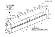
以下、本発明の実施形態について、添付の図面を参照して具体的に説明する。先ず、本発明の第1参考例について説明する。図1は、本発明の第1参考例に係る溶接構造閉断面フレームを示す模式的斜視図である。アルミニウム合金板材がプレス加工等によって成形され、開断面を有するコの字状のフレーム部材1aが形成されている。このフレーム部材1aの内側面に当接して等間隔に矩形状を有する内部補強材2が接続され、フレーム部材1aと同形状を有するフレーム部材1bがフレーム部材1aと対向した状態で、その開放端縁部同士をミグ(MIG:Metal Inert Gas)溶接等によって接続され、これにより内部補強材2が設けられた口の字状の閉断面を有する溶接構造閉断面フレームが形成されている。本実施形態においてはフレームの溶接部が突合せ継手になっている。
Hereinafter, embodiments of the present invention will be specifically described with reference to the accompanying drawings. First, a first reference example of the present invention will be described. FIG. 1 is a schematic perspective view showing a welded structure closed section frame according to a first reference example of the present invention. An aluminum alloy sheet is formed by press working or the like to form a
次に、上述の如く構成された本参考例の溶接構造閉断面フレームの動作について説明する。車両の衝突時等、溶接構造閉断面フレームの長手方向に外力が付加されると、溶接構造閉断面フレームが変形する。これにより、外力によるエネルギーを吸収する。このとき、内部補強材2はフレーム部材の溶接部が存在する相対した面を結ぶ方向の圧縮強度がこの方向と直角であるいずれの方向の圧縮強度よりも高いため、溶接部が内側に凹むように変形することはなく、よって溶接部が開口することはない。
Next, the operation of the welded structure closed section frame of this reference example configured as described above will be described. When an external force is applied in the longitudinal direction of the welded structure closed section frame, such as during a vehicle collision, the welded structure closed section frame is deformed. Thereby, the energy by external force is absorbed. At this time, the internal reinforcing
次に、本発明の第2参考例について説明する。図2は本参考例に係る溶接構造閉断面フレームを示す模式的斜視図である。図2において図1と同一構成物には同一符号を付して、その詳細な説明は省略する。アルミニウム合金板材がプレス加工等によって成形され、開断面を有するコの字状のフレーム部材1aが形成されている。このフレーム部材1aの内側面に当接して等間隔に矩形状を有する内部補強材2が接続され、フレーム部材1aの外側面の間隔と等しい内側面の間隔を有するフレーム部材1cがフレーム部材1aと対向した状態で、その開放端縁部同士が一部重なりを有した状態でミグ溶接等によって接続され、即ち重ねすみ肉溶接され、これにより内部補強材2が設けられた溶接構造閉断面フレームが形成されている。本実施形態においてはフレームの溶接部が重ね継手になっている。
Next, a second reference example of the present invention will be described. FIG. 2 is a schematic perspective view showing a welded structure closed section frame according to the present reference example. 2, the same components as those in FIG. 1 are denoted by the same reference numerals, and detailed description thereof is omitted. An aluminum alloy sheet is formed by press working or the like to form a
次に、上述の如く構成された本参考例の溶接構造閉断面フレームの動作について説明する。上述の第1参考例に係る溶接構造閉断面フレームの動作と同様、車両の衝突時等、溶接構造閉断面フレームの長手方向に外力が付加されると、溶接構造閉断面フレームが変形する。これにより、外力によるエネルギーを吸収する。また、このとき上述の第1実施形態と同様の効果により溶接部が開口しない。 Next, the operation of the welded structure closed section frame of this reference example configured as described above will be described. Similar to the operation of the welded structure closed section frame according to the first reference example described above, when an external force is applied in the longitudinal direction of the welded structure closed section frame during a vehicle collision or the like, the welded structure closed section frame is deformed. Thereby, the energy by external force is absorbed. At this time, the welded portion does not open due to the same effect as in the first embodiment.
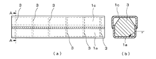
次に、本発明の第3参考例について説明する。図3(a)及び図4(a)は本参考例に係る溶接構造閉断面フレームを示す模式的側面図、図3(b)及び図4(b)は図3(a)及び図4(a)におけるA−A線断面図である。図3及び4において図1及び2と同一構成物には同一符号を付して、その詳細な説明は省略する。 Next, a third reference example of the present invention will be described. 3 (a) and 4 (a) are schematic side views showing a welded structure closed section frame according to this reference example, and FIGS. 3 (b) and 4 (b) are FIGS. 3 (a) and 4 (b). It is an AA line sectional view in a). 3 and 4, the same components as those in FIGS. 1 and 2 are denoted by the same reference numerals, and detailed description thereof is omitted.
アルミニウム合金板材がプレス加工等によって成形され、開断面を有するコの字状のフレーム部材1aが形成されている。このフレーム部材1aの内側面に当接して等間隔に内部補強材3が接続されている。この内部補強材3は、フレーム部材1aのコの字状の対向する辺よりも長く形成されており、フレーム部材1aの対向する2辺に接しない部分が内側に傾斜していることにより、隅部に傾斜部が設けられている。また、内部補強材3の長さとフレーム部材1aの内側の底面からフレーム部材1aの先端までの長さとの差は、フレーム部材1aの先端とフレーム部材1cの内側の底面までの長さと等しく設計されている。
An aluminum alloy sheet is formed by press working or the like to form a
本参考例においては、図4(b)に示すように、内部補強材3とフレーム部材1aとが、コの字状のフレームの側面のみにおいて接続されている。そして、フレーム部材1aの外側面の間隔と等しい内側面の間隔を有するフレーム部材1cがフレーム部材1aと対向し、一部が内部補強材3の高さによって決まる重なりを有した状態でミグ溶接等によって接続され、即ち重ねすみ肉溶接され、これにより内部補強材3が設けられた溶接構造閉断面フレームが形成されている。
In the present reference example, as shown in FIG. 4B, the internal reinforcing
重ね継手で溶接を行う場合、所望の重ね継手長さになるようにフレーム部材1aとフレーム部材1cとを位置決めすることが難しいが、本参考例においては内部補強材3が双方のフレーム部材の底面に当接する形状になっている。これにより、内部補強材3は溶接構造閉断面フレームを補強する機能だけでなく、フレーム溶接部の位置決めとしての機能も兼ね備えている。
When welding with a lap joint, it is difficult to position the
次に、上述の如く構成された本参考例の溶接構造閉断面フレームの動作について説明する。上述の第1及び第2参考例に係る溶接構造閉断面フレームの動作と同様、車両の衝突時等、溶接構造閉断面フレームの長手方向に外力が付加されると、溶接構造閉断面フレームが変形する。このとき、第1及び第2参考例とは異なり、内部補強材3がフレーム部材1a及び1cの双方に接していることにより、外力によるエネルギーを吸収するときに、この吸収エネルギーがより高くなる。また、このとき、内部補強材3は隅部に傾斜部が設けられており、フレーム部材の溶接部が存在する相対した面を結ぶ方向の圧縮強度がこの方向と直角であるいずれの方向の圧縮強度よりも高いため、溶接部が内側に凹むように変形することはなく、よって溶接部が開口することはない。
Next, the operation of the welded structure closed section frame of this reference example configured as described above will be described. Similar to the operation of the welded structure closed section frame according to the first and second reference examples described above, when an external force is applied in the longitudinal direction of the welded structure closed section frame, such as during a vehicle collision, the welded structure closed section frame is deformed. To do. At this time, unlike the first and second reference examples, since the internal reinforcing
次に、本発明の第4参考例について説明する。図5(a)は本参考例に係る溶接構造閉断面フレームを示す模式的側面図、図5(b)は図5(a)におけるA−A線断面図である。図5において図1乃至4と同一構成物には同一符号を付して、その詳細な説明は省略する。 Next, a fourth reference example of the present invention will be described. FIG. 5A is a schematic side view showing a welded structure closed section frame according to this reference example, and FIG. 5B is a sectional view taken along line AA in FIG. 5, the same components as those in FIGS. 1 to 4 are denoted by the same reference numerals, and detailed description thereof is omitted.
上述の第3参考例は、図4に示すように内部補強材3とフレーム部材1aとがコの字状のフレームの側面のみにおいて接続されているのに対し、本第4参考例においては図5に示すように内部補強材3とフレーム部材1aとがコの字状のフレームの底面のみにおいて接続されている点が異なり、それ以外は第3参考例と同様の構造を有している。本参考例に係る溶接構造閉断面フレームは、上述の第3参考例の動作及び得られる効果に加え、内部補強材3が底面のみにおいて接続され、側面においては接続されていないため、側面が凸形状に変形する吸収形態が促され、この結果、溶接部の開口破断が起こらない。
In the third reference example described above, the internal reinforcing
次に、本発明の第5参考例について説明する。図6(a)は本参考例に係る溶接構造閉断面フレームを示す模式的側面図、図6(b)は図6(a)におけるA−A線断面図である。図6において図1乃至5と同一構成物には同一符号を付して、その詳細な説明は省略する。 Next, a fifth reference example of the present invention will be described. FIG. 6A is a schematic side view showing a welded structure closed section frame according to this reference example, and FIG. 6B is a sectional view taken along line AA in FIG. 6, the same components as those in FIGS. 1 to 5 are denoted by the same reference numerals, and detailed description thereof is omitted.
アルミニウム合金板材がプレス加工等によって成形され、開断面を有するコの字状のフレーム部材1aが形成されている。また、フレーム部材1aの外側面の間隔と等しい内側面の間隔を有するフレーム部材1cの内側面に当接して等間隔に矩形状を有する内部補強材4が接続され、フレーム部材1aとフレーム部材1cとが対向したときにフレーム部材1aの先端部が内部補強材4の先端部に接するようになっている。これにより、内部補強材4は溶接構造閉断面フレームを補強する機能だけでなく、フレーム溶接部の位置決めとしての機能も兼ね備えている。フレーム部材1aとフレーム部材1cとを対向させ、一部が内部補強材4の高さによって決まる重なりを有した状態でミグ溶接等によって接続され、即ち重ねすみ肉溶接され、これにより内部補強材4が設けられた溶接構造閉断面フレームが形成されている。本参考例の動作及び得られる効果は上述の第2参考例と同様である。
An aluminum alloy sheet is formed by press working or the like to form a
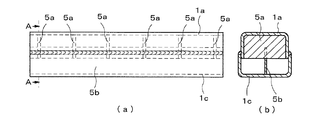
次に、本発明の実施形態について説明する。図7(a)は本実施形態に係る溶接構造閉断面フレームを示す模式的側面図、図7(b)は図7(a)におけるA−A線断面図である。図7において図1乃至6と同一構成物には同一符号を付して、その詳細な説明は省略する。 Next, an embodiment of the present invention will be described. Fig.7 (a) is a typical side view which shows the welding structure closed cross-section frame which concerns on this embodiment, FIG.7 (b) is the sectional view on the AA line in Fig.7 (a). 7, the same components as those in FIGS. 1 to 6 are denoted by the same reference numerals, and detailed description thereof is omitted.
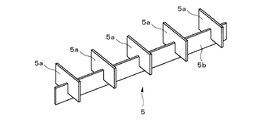
図8は本実施形態の内部補強材5の形状を示す模式的斜視図である。図8において図1乃至7と同一構成物には同一符号を付して、その詳細な説明は省略する。フレーム部材1cの長手方向の長さと同寸法を有する板材5bは切削加工等によって等間隔に切り込みを設けられ、この切り込みに溶接線と直角方向に内部補強部材5aが挿入されることによって内部補強材5が形成されている。内部補強材5は双方のフレーム部材の底面に当接する形状になっているため、内部補強材5は溶接構造閉断面フレームを補強する機能だけでなく、フレーム溶接部の位置決めとしての機能も兼ね備えている。また、内部補強材5はこれ自体で自立するため、内部補強材5とフレーム部材1a及び1cとは特に溶接されず、フレーム部材1cの内部に内部補強材5が挿入された状態でフレーム部材1aを対向させ、フレーム部材1aと1cとが一部が内部補強材5の高さによって決まる重なりを有した状態でミグ溶接等によって接続され、即ち重ねすみ肉溶接され、これにより内部補強材5が設けられた閉断面フレームが形成されている。
FIG. 8 is a schematic perspective view showing the shape of the internal reinforcing
次に、上述の如く構成された本実施形態の溶接構造閉断面フレームの動作について説明する。上述の第1乃至5参考例に係る溶接構造閉断面フレームの動作と同様、車両の衝突時等、溶接構造閉断面フレームの長手方向に外力が付加されると、溶接構造閉断面フレームが変形する。このとき、第1及び第2参考例とは異なり、内部補強材5がフレーム部材1a及び1cの双方に接していることにより、外力によるエネルギーを吸収するときに、この吸収エネルギーがより高くなる。また、このとき、内部補強材5にはフレーム部材の溶接部が存在する相対した面を結ぶ方向と直角の方向に切り込みが設けられているため、この切り込みが設けられている方向の圧縮強度が弱くなり、従って、溶接部が存在する相対した面を結ぶ方向の圧縮強度が相対的に高くなり、これにより、溶接部が内側に凹むように変形することはなく、よって溶接部が開口することはない。
Next, the operation of the welded structure closed section frame of the present embodiment configured as described above will be described. Similar to the operation of the welded structure closed section frame according to the first to fifth reference examples described above, when an external force is applied in the longitudinal direction of the welded structure closed section frame during a vehicle collision or the like, the welded structure closed section frame is deformed. . At this time, unlike the first and second reference examples, since the internal reinforcing
なお、上述の第1乃至5参考例における内部補強材2乃至4及び本発明の実施形態における板材5bは、溶接構造閉断面フレームの長手方向に等間隔に設けられているが、これらは必ずしも等間隔に設けられる必要はなく、溶接構造閉断面フレームの外部及び内部の構造を考慮して、適切な間隔で設けられることができる。
The internal reinforcing
次に、本発明の第6参考例について説明する。図9(a)は本参考例に係る溶接構造閉断面フレームを示す模式的側面図、図9(b)は図9(a)におけるA−A線断面図である。図9において図1乃至8と同一構成物には同一符号を付して、その詳細な説明は省略する。 Next, a sixth reference example of the present invention will be described. Fig.9 (a) is a typical side view which shows the welded structure closed cross-section frame which concerns on this reference example, FIG.9 (b) is the sectional view on the AA line in Fig.9 (a). 9, the same components as those in FIGS. 1 to 8 are denoted by the same reference numerals, and detailed description thereof is omitted.
本参考例の内部補強材6は、一辺がフレーム部材1aの底辺の内側面の長さよりも短い口型押出形材がフレーム部材1aの長手方向の長さよりも短い長さに切断され、これらが複数個横に並べられた状態で溶接等により接続されて形成されている。そして、口型押出形材は、押出方向が溶接部が存在する面を結ぶ方向と一致するようにフレーム内に配置されている。この内部補強材6は押出形材が切断され、溶接等により接続されているだけであるため、上述の本発明の実施形態の内部補強材5のように切削加工により切り込みを入れて作成する方法に比べ、加工コストが非常に安価である。また、切断された口型押出形材同士の接続は、仮付け程度でよく、大きな接合強度は要求されない。
In the internal reinforcing
フレーム部材1aの内部に内部補強材6が挿入された状態でフレーム部材1cを対向させ、フレーム部材1aと1cとが一部が内部補強材6の高さによって決まる重なりを有した状態でミグ溶接等によって接続され、即ち重ねすみ肉溶接され、これにより内部補強材6が設けられた溶接構造閉断面フレームが形成されている。
The
次に、上述の如く構成された本第6参考例の溶接構造閉断面フレームの動作について説明する。上述の第1乃至5参考例及び本発明の実施形態に係る溶接構造閉断面フレームの動作と同様、車両の衝突時等、溶接構造閉断面フレームの長手方向に外力が付加されると、溶接構造閉断面フレームが変形する。このとき、第1及び第2参考例とは異なり、内部補強材6がフレーム部材1a及び1cの双方に接していることにより、外力によるエネルギーを吸収するときに、この吸収エネルギーがより高くなる。また、このとき、口型押出形材が、押出方向が溶接部が存在する面を結ぶ方向と一致するようにフレーム内に配置されているため、内部補強材6はフレーム部材の溶接部が存在する相対した面を結ぶ方向の圧縮強度がこの方向と直角であるいずれの方向の圧縮強度よりも高い。これにより、溶接部が内側に凹むように変形することはなく、よって溶接部が開口することはない。
Next, the operation of the welded structure closed section frame of the sixth reference example configured as described above will be described. Similar to the operation of the welded structure closed section frame according to the first to fifth reference examples and the embodiment of the present invention, when an external force is applied in the longitudinal direction of the welded structure closed section frame, such as during a vehicle collision, the welded structure The closed section frame is deformed. At this time, unlike the first and second reference examples, since the internal reinforcing
なお、上述の第6参考例における内部補強材6は同一の押出形材から切断した同断面形状の形材を使用しているが、必ずしも同形状の形材を使用する必要はなく、溶接構造閉断面フレームの内部の構造を考慮して、複数種の形材を使用することもできる。
In addition, although the internal reinforcing
以下、本発明の効果を実証するための実施例について説明する。本発明の参考試験例1として、図1に示す上述の第1参考例に係る溶接構造閉断面フレームを作成した。フレーム部材1a及び1bは、板厚4mmのA5454P−Oアルミニウム合金板材を使用し、開断面を有するよう、プレス加工によって成形した。フレーム部材1a及び1bの長手方向の長さは500mm、底辺の長さは外側面において100mmである。
Examples for demonstrating the effects of the present invention will be described below. As Reference Test Example 1 of the present invention, a welded structure closed section frame according to the first reference example shown in FIG. 1 was prepared. The
内部補強材2としては、同じく板厚4mmのA5454P−Oアルミニウム合金板材を矩形に成形し、フレーム部材1aの端部から50mmの部位から内側面に当接して100mmの等間隔で配置し、ミグ溶接によって接続した。
As the internal reinforcing
その後、フレーム部材1aと1bとを対向させた状態でフレーム溶接部が突合せ継手となるようにミグ溶接を行い、これにより高さが100mmの溶接構造閉断面フレームを作成した。また、ミグ溶接は線径1.2mmのA4043WY溶接ワイヤを使用し、通常のミグ溶接機によって行った。
Thereafter, MIG welding was performed with the
これにより、高さ100mm、幅100mm、長さ500mmで、フレーム部材1aの内部に100mm間隔で5個の内部補強材2が配置され、突合せ継手を有する溶接構造閉断面フレームを作成した。
As a result, a closed cross-section frame having a height of 100 mm, a width of 100 mm, and a length of 500 mm, having five internal reinforcing
また、比較例1として、図10に示すように、上述の参考試験例1において、フレーム部材1aの内側面に内部補強材2を配置していないもの、即ち100mm×100mmの閉断面及び500mmの長さを有し、突合せ継手を有する溶接構造閉断面フレームを作成した。図10において図1乃至9と同一構成物には同一符号を付して、その詳細な説明は省略する。
Further, as Comparative Example 1, as shown in FIG. 10, in Reference Test Example 1 described above, the inner reinforcing
また、本発明の参考試験例2として、図2に示す上述の第2参考例に係る溶接構造閉断面フレームを作成した。フレーム部材1a及び1cは、板厚4mmのA5454P−Oアルミニウム合金板材を使用し、開断面を有するよう、プレス加工によって成形した。フレーム部材1a及び1bの長手方向の長さは500mm、フレーム部材1aの底辺の長さは外側面において100mm、フレーム部材1cの底辺の長さは外側面において108mmである。
Further, as Reference Test Example 2 of the present invention, a welded structure closed section frame according to the second reference example shown in FIG. 2 was prepared. The
内部補強材2としては、同じく板厚4mmのA5454P−Oアルミニウム合金板材を矩形に成形し、フレーム部材1aの端部から50mmの部位から内側面に当接して100mmの等間隔で配置し、ミグ溶接によって接続した。
As the internal reinforcing
その後、フレーム部材1aと1cとが一部重なりを有した状態で、フレーム溶接部が重ね継手となるようにミグ溶接を行い、即ち重ねすみ肉溶接を行い、これにより高さが100mmの溶接構造閉断面フレームを作成した。また、ミグ溶接は線径1.2mmのA4043WY溶接ワイヤを使用し、通常のミグ溶接機によって行った。
After that, with the
これにより、高さ100mm、大きい方の幅108mm、小さい方の幅100mm、長さ500mmで、フレーム部材1aの内部に100mm間隔で5個の内部補強材2が配置され、重ね継手を有する溶接構造閉断面フレームを作成した。
As a result, a welded structure having a height joint of 100 mm, a larger width of 108 mm, a smaller width of 100 mm, a length of 500 mm, five internal reinforcing
また、比較例2として、図11に示すように、上述の参考試験例2において、フレーム部材1aの内側面に内部補強材2を配置していない溶接構造閉断面フレームを作成した。図11において図1乃至10と同一構成物には同一符号を付して、その詳細な説明は省略する。
Further, as Comparative Example 2, as shown in FIG. 11, a welded structure cross-section frame in which the internal reinforcing
また、本発明の参考試験例3として、図4に示す上述の第3参考例に係る溶接構造閉断面フレームを作成した。フレーム部材1a、1c及び内部補強材3には、参考試験例1及び2と同様に板厚4mmのA5454P−Oアルミニウム合金板材を使用した。図4(b)に示すように、内部補強材3とフレーム部材1aとは、コの字状のフレームの側面のみにおいてミグ溶接によって接続した。そして、フレーム部材1aとフレーム部材1cとを、一部が内部補強材3の高さによって決まる重なりを有した状態でミグ溶接によって接続し、即ち重ねすみ肉溶接を行い、これにより高さが100mmの溶接構造閉断面フレームを作成した。また、ミグ溶接は線径1.2mmのA4043WY溶接ワイヤを使用し、通常のミグ溶接機によって行った。
Further, as Reference Test Example 3 of the present invention, a welded structure closed cross-section frame according to the above-described third reference example shown in FIG. 4 was prepared. As the
また、本発明の参考試験例4として、図5に示す上述の第4参考例に係る溶接構造閉断面フレームを作成した。参考試験例3の溶接構造閉断面フレームが図4に示すように内部補強材3とフレーム部材1aとがコの字状のフレームの側面のみにおいて溶接されているのに対し、本参考試験例4は図5に示すように内部補強材3とフレーム部材1aとがコの字状のフレームの底面のみにおいて溶接されている点が異なり、それ以外は実施例3と同様の構造を有するよう作成した。
Further, as Reference Test Example 4 of the present invention, a welded structure closed section frame according to the above-mentioned fourth reference example shown in FIG. 5 was prepared. In the closed cross-section frame of the reference test example 3, as shown in FIG. 4, the internal reinforcing
また、本発明の参考試験例5として、図6に示す上述の第5参考例に係る溶接構造閉断面フレームを作成した。フレーム部材1a、1c及び内部補強材4には、参考試験例1乃至4と同様に板厚4mmのA5454P−Oアルミニウム合金板材を使用した。図6(b)に示すように、フレーム部材1cの内側面に当接して等間隔に矩形状を有する内部補強材4を配置し、ミグ溶接によって接続した。そして、フレーム部材1aとフレーム部材1cとを、一部が内部補強材4の高さによって決まる重なりを有した状態でミグ溶接によって接続し、即ち重ねすみ肉溶接を行い、これにより高さが100mmの溶接構造閉断面フレームを作成した。また、ミグ溶接は線径1.2mmのA4043WY溶接ワイヤを使用し、通常のミグ溶接機によって行った。
Further, as Reference Test Example 5 of the present invention, a welded structure closed section frame according to the above-mentioned fifth reference example shown in FIG. 6 was prepared. As the
また、本発明の実施例として、図7に示す上述の本発明の実施形態に係る溶接構造閉断面フレームを作成した。フレーム部材1a、1c及び内部補強材5には、参考試験例1乃至5と同様に板厚4mmのA5454P−Oアルミニウム合金板材を使用した。フレーム部材1cの長手方向の長さと同寸法を有する板材5bに切削加工等によって等間隔に切り込みを設け、この切り込みに溶接線と直角方向に内部補強部材5aを挿入することによって内部補強材5を形成した。内部補強材5はこれ自体で自立するため、内部補強材5とフレーム部材1a及び1cとは特に接続せず、フレーム部材1cの内部に内部補強材5を挿入した状態でフレーム部材1aを対向させ、フレーム部材1aと1cとが一部が内部補強材5の高さによって決まる重なりを有した状態でミグ溶接によって接続し、即ち重ねすみ肉溶接を行い、これにより高さが100mmの溶接構造閉断面フレームを作成した。また、ミグ溶接は線径1.2mmのA4043WY溶接ワイヤを使用し、通常のミグ溶接機によって行った。
Further, as an example of the present invention, a welded structure closed section frame according to the above-described embodiment of the present invention shown in FIG. 7 was created. As the
また、本発明の参考試験例6として、図9に示す上述の第6参考例に係る溶接構造閉断面フレームを作成した。一辺が80mmで肉厚が2.5mmのA6063−T5アルミニウム合金製口型押出形材を長さ85mmに切断し、この切断された口型押出形材同士を横に並べてミグ溶接により接続し、内部補強材6を形成した。フレーム部材1aの内部に内部補強材6を挿入した状態でフレーム部材1cを対向させ、フレーム部材1aと1cとが一部が内部補強材6の高さによって決まる重なりを有した状態でミグ溶接によって接続し、即ち重ねすみ肉溶接を行い、これにより高さが100mmの閉断面フレームを作成した。また、ミグ溶接は線径1.2mmのA4043WY溶接ワイヤを使用し、通常のミグ溶接機によって行った。
Further, as Reference Test Example 6 of the present invention, a welded structure closed cross-section frame according to the above-described sixth reference example shown in FIG. 9 was prepared. Cut the A6063-T5 aluminum alloy mold extrusions with a side of 80 mm and a wall thickness of 2.5 mm to a length of 85 mm, and connect the cut mold extrusions side by side by MIG welding. An
上述の実施例、参考試験例1乃至6、及び比較例1乃至2の評価は100tonの万能材料試験機により溶接構造閉断面フレームの縦方向(長手方向)の圧縮試験によって行った。圧縮試験は各溶接構造閉断面フレームを100mm圧縮し、各溶接構造閉断面フレームの全長が400mmになったところで終了し、各溶接構造閉断面フレームの破壊状況を観察した。 The above-mentioned Examples, Reference Test Examples 1 to 6 and Comparative Examples 1 to 2 were evaluated by a compression test in the longitudinal direction (longitudinal direction) of the welded structure closed section frame using a 100 ton universal material testing machine. The compression test was finished when each welded structure closed section frame was compressed by 100 mm, and when the total length of each welded structure closed section frame reached 400 mm, the fracture state of each welded structure closed section frame was observed.
その結果、比較例1及び2の溶接構造閉断面フレーム、即ち内部補強材2が内側に設置されていない溶接構造閉断面フレームは、万能材料試験機によって縦圧縮荷重を付加していくと、溶接構造閉断面フレームの溶接部が内側に凹むように変形し、溶接部で開口し、破断した。
As a result, the welded structure closed section frame of Comparative Examples 1 and 2, that is, the welded structure closed section frame in which the internal reinforcing
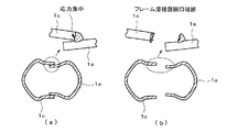
図12は比較例2の溶接構造閉断面フレームの破壊状況を示す模式的斜視図、図13(a)は図12におけるA−A線断面図、図13(b)は同じくB−B線断面図である。図12及び13において図1乃至11と同一構成物には同一符号を付して、その詳細な説明は省略する。特に、比較例2の重ね継手を有する溶接構造閉断面フレームは、上板と下板との界面と溶接金属部との交点に応力が集中するため、図13(b)に示すように、溶接部において大きく開口し、破断した。比較例1の突合せ継手を有する溶接構造閉断面フレームも、溶接部近傍に応力が集中し破断するものの、比較例2の溶接構造閉断面フレーム程大きくは開口しなかった。 12 is a schematic perspective view showing a fracture state of the welded structure closed section frame of Comparative Example 2, FIG. 13 (a) is a sectional view taken along the line AA in FIG. 12, and FIG. 13 (b) is a sectional view taken along the line BB. FIG. 12 and 13, the same components as those in FIGS. 1 to 11 are denoted by the same reference numerals, and detailed description thereof is omitted. In particular, in the welded structure closed section frame having the lap joint of Comparative Example 2, since stress concentrates at the intersection of the interface between the upper plate and the lower plate and the weld metal part, as shown in FIG. A large opening was formed at the part, and fractured. The welded structure closed section frame having the butt joint of Comparative Example 1 also did not open as much as the welded structure closed section frame of Comparative Example 2 although the stress concentrated in the vicinity of the weld and fractured.
一方、参考試験例1及び2の溶接構造閉断面フレーム、即ち内部補強材2が内側に接続されている溶接構造閉断面フレームは、図14に示すように溶接部が凸状に変形し、溶接金属に割れが入るものの、継手が破断して大きく開口することはなかった。図15は図14におけるA−A線断面図である。図14及び15において図1乃至13と同一構成物には同一符号を付して、その詳細な説明は省略する。
On the other hand, in the welded structure closed section frame of Reference Test Examples 1 and 2, that is, the welded structure closed section frame in which the internal reinforcing
また、実施例及び参考試験例3乃至6は、いずれの溶接構造閉断面フレームにおいてもフレームの溶接部で大きく開口破断することはなかった。ただし、参考試験例3のように内部補強材3とフレーム部材1aとを、コの字状のフレームの側面のみにおいてミグ溶接によって接続したものは、内部補強材3と接している部分のフレームの溶接部は破断しないものの、内部補強材3と内部補強材3との間ではフレームの溶接部が破断した。ただし図12に示すように大きく開口することはなかった。
Further, in Examples and Reference Test Examples 3 to 6, there was no large opening fracture at the welded part of the frame in any welded structure closed section frame. However, as in Reference Test Example 3, the inner reinforcing
参考試験例4の溶接構造閉断面フレームは、参考試験例3と同様の内部補強材3を有しており、参考試験例3のように内部補強材3とフレーム部材1aとを、コの字状のフレームの側面のみにおいてミグ溶接によって溶接するのではなく、内部補強材3とフレーム部材1aとを、コの字状のフレーム部材1aの底面のみにおいてミグ溶接によって溶接したものである。参考試験例4においては、フレームの溶接部がある側面(コの字フレームの側面)が凸状に変形したが、溶接部が図12のように大きく開口し、破断することはなかった。
The welded structure closed cross-section frame of Reference Test Example 4 has the same internal reinforcing
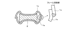
また、参考試験例6の溶接構造閉断面フレームは、図16に示すように内部補強材6の壁面がくの字状に変形したが、最も大きく変形した部位の前後(図16に示す部位A)においてもフレームの溶接部が内側に凹むようには変形しなかった。即ち、溶接構造閉断面フレームの縦方向の圧縮変形と同時に内部補強材6も変形し、図16に示す部位Aがフレーム部材1a及び1cに当接し、フレームの溶接部が内側に変形しないよう補強されるため、実施例、参考試験例1乃至6及び比較例1乃至2の中で破断(割れ)が最も少なかった。
Further, in the closed cross-sectional frame of the welded structure of Reference Test Example 6, as shown in FIG. 16, the wall surface of the internal reinforcing
開断面を有する2個のアルミニウム合金製のフレーム部材を溶接することにより閉断面を構成する溶接構造閉断面フレームにおいて、溶接構造閉断面フレームの内部にフレーム部材の内側面に当接して内部補強材を配置することにより、衝突時等フレームに外力が付加され圧壊するときに、溶接された2個のフレーム部材が溶接部において大きく開口しないため、圧壊時の吸収エネルギーの低下がなく、鋭利な開口部破断面の露出により乗員及び周辺環境を傷つける虞がない。 In a welded structure closed cross-section frame that forms a closed cross-section by welding two aluminum alloy frame members having an open cross-section, the inner reinforcing material is in contact with the inner surface of the frame member inside the welded structure closed cross-section frame When the external force is applied to the frame at the time of a collision and the like, the two welded frame members do not open greatly at the welded part, so there is no decrease in the absorbed energy at the time of the collapse and a sharp opening There is no risk of damaging the occupant and the surrounding environment due to the exposed fracture surface.
1a、1b、1c ; フレーム部材
2、3、4、5、6 ; 内部補強材
5a ; 内部補強部材
5b ; 板材
1a, 1b, 1c;
Claims (3)
Priority Applications (1)
| Application Number | Priority Date | Filing Date | Title |
|---|---|---|---|
| JP2009269705A JP4993520B2 (en) | 2009-11-27 | 2009-11-27 | Welded structure closed section frame |
Applications Claiming Priority (1)
| Application Number | Priority Date | Filing Date | Title |
|---|---|---|---|
| JP2009269705A JP4993520B2 (en) | 2009-11-27 | 2009-11-27 | Welded structure closed section frame |
Related Parent Applications (1)
| Application Number | Title | Priority Date | Filing Date |
|---|---|---|---|
| JP2006094614A Division JP4562677B2 (en) | 2006-03-30 | 2006-03-30 | Welded structure closed section frame |
Publications (2)
| Publication Number | Publication Date |
|---|---|
| JP2010076762A true JP2010076762A (en) | 2010-04-08 |
| JP4993520B2 JP4993520B2 (en) | 2012-08-08 |
Family
ID=42207670
Family Applications (1)
| Application Number | Title | Priority Date | Filing Date |
|---|---|---|---|
| JP2009269705A Active JP4993520B2 (en) | 2009-11-27 | 2009-11-27 | Welded structure closed section frame |
Country Status (1)
| Country | Link |
|---|---|
| JP (1) | JP4993520B2 (en) |
Cited By (1)
| Publication number | Priority date | Publication date | Assignee | Title |
|---|---|---|---|---|
| JP2020011688A (en) * | 2018-07-20 | 2020-01-23 | 日本製鉄株式会社 | Vehicle structural member |
Citations (4)
| Publication number | Priority date | Publication date | Assignee | Title |
|---|---|---|---|---|
| JPH0920267A (en) * | 1995-07-07 | 1997-01-21 | Hino Motors Ltd | Pillar structure of automobile |
| JP2001262771A (en) * | 2000-03-23 | 2001-09-26 | Daiken Trade & Ind Co Ltd | Core member for panel and panel using the same |
| JP2003175858A (en) * | 2001-12-12 | 2003-06-24 | Kobe Steel Ltd | Aluminum alloy vehicle body frame |
| JP2004249807A (en) * | 2003-02-19 | 2004-09-09 | Toyota Motor Corp | Skeleton structure of car body |
-
2009
- 2009-11-27 JP JP2009269705A patent/JP4993520B2/en active Active
Patent Citations (4)
| Publication number | Priority date | Publication date | Assignee | Title |
|---|---|---|---|---|
| JPH0920267A (en) * | 1995-07-07 | 1997-01-21 | Hino Motors Ltd | Pillar structure of automobile |
| JP2001262771A (en) * | 2000-03-23 | 2001-09-26 | Daiken Trade & Ind Co Ltd | Core member for panel and panel using the same |
| JP2003175858A (en) * | 2001-12-12 | 2003-06-24 | Kobe Steel Ltd | Aluminum alloy vehicle body frame |
| JP2004249807A (en) * | 2003-02-19 | 2004-09-09 | Toyota Motor Corp | Skeleton structure of car body |
Cited By (2)
| Publication number | Priority date | Publication date | Assignee | Title |
|---|---|---|---|---|
| JP2020011688A (en) * | 2018-07-20 | 2020-01-23 | 日本製鉄株式会社 | Vehicle structural member |
| JP7107055B2 (en) | 2018-07-20 | 2022-07-27 | 日本製鉄株式会社 | Vehicle structural member |
Also Published As
| Publication number | Publication date |
|---|---|
| JP4993520B2 (en) | 2012-08-08 |
Similar Documents
| Publication | Publication Date | Title |
|---|---|---|
| JP4562677B2 (en) | Welded structure closed section frame | |
| JP6228180B2 (en) | Body front structure | |
| JP5211133B2 (en) | Body front structure | |
| JP6604383B2 (en) | Steel plate member combination structure, automotive structural member, center pillar, bumper, and door beam | |
| KR101947929B1 (en) | Automobile member | |
| KR102141455B1 (en) | Car absence | |
| JP2008018792A (en) | Shock absorbing member for vehicle | |
| JP2008261493A (en) | Shock absorbing member and its manufacturing method | |
| JP2006015859A (en) | Front vehicle body structure of vehicle | |
| CN109808466B (en) | Car door anti-collision beam | |
| JP2002079388A (en) | Method for laser beam welding of shock-absorbing member having excellent shock absorption characteristic against axial collapse | |
| JP2010083381A (en) | Bumper system and method for manufacturing the same | |
| JP5131810B2 (en) | Crash box and manufacturing method thereof | |
| JP2019073152A (en) | Side rail and manufacturing method for side rail | |
| KR20180027562A (en) | Bumper reinforcement and vehicles equipped with it | |
| JP2006111228A (en) | Truck chassis frame and aluminum alloy for frame | |
| JP4993520B2 (en) | Welded structure closed section frame | |
| JP4469153B2 (en) | Automotive bumper equipment | |
| JP2006142917A (en) | Shock absorbing member having excellent shock absorbing property and welding method therefor | |
| JP4333310B2 (en) | Automotive bumper equipment | |
| JP2005075293A (en) | Shock absorbing structure for railway vehicle | |
| JP5180950B2 (en) | Bumper structure | |
| JP2008168897A (en) | Bumper device for automobile | |
| JP2019084847A (en) | Vehicle body structure | |
| JP6172426B1 (en) | Automotive parts |
Legal Events
| Date | Code | Title | Description |
|---|---|---|---|
| A131 | Notification of reasons for refusal |
Free format text: JAPANESE INTERMEDIATE CODE: A131 Effective date: 20110823 |
|
| A977 | Report on retrieval |
Free format text: JAPANESE INTERMEDIATE CODE: A971007 Effective date: 20110825 |
|
| A521 | Written amendment |
Free format text: JAPANESE INTERMEDIATE CODE: A523 Effective date: 20111011 |
|
| TRDD | Decision of grant or rejection written | ||
| A01 | Written decision to grant a patent or to grant a registration (utility model) |
Free format text: JAPANESE INTERMEDIATE CODE: A01 Effective date: 20120501 |
|
| A01 | Written decision to grant a patent or to grant a registration (utility model) |
Free format text: JAPANESE INTERMEDIATE CODE: A01 |
|
| A61 | First payment of annual fees (during grant procedure) |
Free format text: JAPANESE INTERMEDIATE CODE: A61 Effective date: 20120501 |
|
| FPAY | Renewal fee payment (event date is renewal date of database) |
Free format text: PAYMENT UNTIL: 20150518 Year of fee payment: 3 |
|
| R150 | Certificate of patent or registration of utility model |
Free format text: JAPANESE INTERMEDIATE CODE: R150 Ref document number: 4993520 Country of ref document: JP Free format text: JAPANESE INTERMEDIATE CODE: R150 |