JP2010074688A - Apparatus and method for visualizing fault part of ip network, and recording medium - Google Patents
Apparatus and method for visualizing fault part of ip network, and recording medium Download PDFInfo
- Publication number
- JP2010074688A JP2010074688A JP2008241961A JP2008241961A JP2010074688A JP 2010074688 A JP2010074688 A JP 2010074688A JP 2008241961 A JP2008241961 A JP 2008241961A JP 2008241961 A JP2008241961 A JP 2008241961A JP 2010074688 A JP2010074688 A JP 2010074688A
- Authority
- JP
- Japan
- Prior art keywords
- network
- packet
- template
- procedure
- communication
- Prior art date
- Legal status (The legal status is an assumption and is not a legal conclusion. Google has not performed a legal analysis and makes no representation as to the accuracy of the status listed.)
- Granted
Links
Images


Landscapes
- Data Exchanges In Wide-Area Networks (AREA)
Abstract
Description
本発明は、IPネットワーク上を流れるパケットからネットワークの故障箇所を可視化するIPネットワークの故障箇所の可視化装置、IPネットワークの故障箇所の可視化方法及び当該方法をコンピュータに実行させるためのプログラムを記録した記録媒体に関する。 The present invention relates to an IP network failure location visualization apparatus that visualizes a failure location of a network from a packet flowing on the IP network, a method for visualizing a failure location of an IP network, and a record that records a program for causing a computer to execute the method. It relates to the medium.
IPネットワーク上を流れるパケットを取得して、ネットワーク構成図およびその構成図上を流れるトラフィックを、全体を鳥瞰しつつ、部分的に詳細に見やすくするために3D化した可視化方法(例えば、非特許文献1を参照。)や、端末数が多い場合でも分かりやすく表現するためにハイパーポリックツリーを用いる手法(例えば、非特許文献2を参照。)が提案されている。なお、本明細書において、ノードとは、一つの端末を示す場合と、複数の端末をまとめたものの両方を指すものとする。
いずれの方法も、パケットを入力として、その情報からネットワーク構成図を生成するため、配線ミス等で、パケットが流れないような故障個所を可視化することができず、本来出現するはずのノードが出現しないことで、配線ミス等の故障を推定しなければならないという課題があった。 Each method takes a packet as an input and generates a network configuration diagram from that information, so it is not possible to visualize a failure location where a packet does not flow due to a wiring error or the like, and a node that should have appeared originally appears. By doing so, there was a problem that a failure such as a wiring mistake had to be estimated.
また、ネットワーク構成図上の各経路の各プロトコルの情報に関しても、疎通のあったプロトコルの情報を可視化したとしても、どの経路にどのようなプロトコルのパケットの疎通があれば正常なのかが不明であるという課題もある。 Also, regarding the protocol information of each route on the network configuration diagram, even if the information on the protocol that was communicated is visualized, it is not clear which protocol packet communication is normal on which route. There is also a problem that there is.
そこで、本発明は、上記課題を解決するためになされたもので、送信元のノードからのパケット又は宛先のノードへのパケットが存在しなくても、本来あるべきノードが表示でき、かつそのノードを送信元又は宛先とするパケットが存在しないことを可視化することができるIPネットワークの故障箇所の可視化装置、IPネットワークの故障箇所の可視化方法及び記録媒体を提供することを第一の目的とする。 Therefore, the present invention has been made to solve the above-mentioned problem, and even if there is no packet from the transmission source node or the packet to the destination node, the original node can be displayed and the node can be displayed. The first object of the present invention is to provide an IP network failure location visualization apparatus, an IP network failure location visualization method, and a recording medium that can visualize that there is no packet having a transmission source or destination as a transmission source.
また、本発明は、ネットワーク構成図上の各経路の各プロトコルの情報を可視化することができるIPネットワークの故障箇所の可視化装置、IPネットワークの故障箇所の可視化方法及び記録媒体を提供することを第二の目的とする。 The present invention also provides an IP network failure location visualization apparatus, an IP network failure location visualization method, and a recording medium that can visualize information of each protocol of each route on a network configuration diagram. Second purpose.
前記第一の目的を達成するために、本発明に係るIPネットワークの故障箇所の可視化装置は、典型的なネットワーク構成をテンプレートとして、初期画面で表示しておき、取得したパケットで生成するネットワーク構成図とその接続状況を、当該テンプレートと重ね合わせることとした。 In order to achieve the first object, a failure location visualization apparatus for an IP network according to the present invention displays a typical network configuration as a template on an initial screen, and generates a network configuration using acquired packets. The figure and its connection status were overlapped with the template.
具体的には、本発明に係るIPネットワークの故障箇所の可視化装置は、監視対象のネットワークを流れるパケットを取得するパケット取得部と、前記ネットワークの構成を示したテンプレートを記憶するテンプレート記憶部と、前記パケット取得部が取得した前記パケットに含まれる情報に基づき、パケットが疎通している経路の疎通ネットワークを推定し、前記疎通ネットワークと前記テンプレート記憶部が記憶する前記テンプレートとを比較し、前記ネットワークの各経路についてパケットの疎通の有無を判断するネットワーク状態演算部と、前記テンプレート記憶部が記憶する前記テンプレートに、前記ネットワーク状態演算部が判断したパケットの疎通の有無を前記ネットワークの経路毎に表示して出力する出力部と、を備える。 Specifically, an apparatus for visualizing a fault location of an IP network according to the present invention includes a packet acquisition unit that acquires a packet flowing through a network to be monitored, a template storage unit that stores a template indicating the configuration of the network, Based on information included in the packet acquired by the packet acquisition unit, a communication network of a route through which a packet is communicated is estimated, the communication network is compared with the template stored in the template storage unit, and the network A network state calculation unit that determines whether or not a packet is communicated with respect to each of the routes; and the template that is stored in the template storage unit displays the presence or absence of the packet communication that is determined by the network state calculation unit for each route of the network And an output unit for outputting.
前記IPネットワークの故障箇所の可視化装置のIPネットワークの故障箇所の可視化方法は、監視対象のネットワークを流れるパケットを取得するパケット取得手順と、前記ネットワークの構成を示したテンプレートを記憶するテンプレート記憶手順と、前記パケット取得手順で取得した前記パケットに含まれる情報に基づき、パケットが疎通している経路の疎通ネットワークを推定し、前記疎通ネットワークと前記テンプレート記憶手順が記憶する前記テンプレートとを比較し、前記ネットワークの各経路についてパケットの疎通の有無を判断するネットワーク状態演算手順と、前記テンプレート記憶手順で記憶した前記テンプレートに、前記ネットワーク状態演算手順で判断したパケットの疎通の有無を前記ネットワークの経路毎に表示して出力する出力手順と、で、IPネットワークの故障箇所を可視化する。 The IP network failure location visualization method of the IP network failure location visualization method includes: a packet acquisition procedure for acquiring a packet flowing through a network to be monitored; a template storage procedure for storing a template indicating the configuration of the network; , Based on information included in the packet acquired in the packet acquisition procedure, estimating a communication network of a route through which the packet communicates, comparing the communication network and the template stored in the template storage procedure, For each route of the network, the network state calculation procedure for determining the presence or absence of packet communication for each route of the network, and the template stored in the template storage procedure, the presence or absence of the packet communication determined in the network state calculation procedure table Output instructions to and outputs, in, to visualize the fault point of an IP network.
領域を限定すると、ネットワーク構成図のパターンは限定される。例えば、任意の企業が提供する家庭のインターネット接続環境ではネットワーク構成は決まってくる。この典型的なネットワーク構成をテンプレートとして初期画面で表示しておき、取得したパケットで生成するネットワーク構成図とその接続状況を、当該テンプレートと重ね合わせることで、パケットの疎通がないノードを検出できる。 When the area is limited, the pattern of the network configuration diagram is limited. For example, the network configuration is determined in a home Internet connection environment provided by an arbitrary company. This typical network configuration is displayed on the initial screen as a template, and a node without packet communication can be detected by superimposing the network configuration diagram generated by the acquired packet and its connection state on the template.
従って、本発明は、送信元のノードからのパケット又は宛先のノードへのパケットが存在しなくても、本来あるべきノードが表示でき、かつそのノードを送信元又は宛先とするパケットが存在しないことを可視化することができるIPネットワークの故障箇所の可視化装置及びIPネットワークの故障箇所の可視化方法を提供することができる。 Therefore, according to the present invention, even if there is no packet from the transmission source node or to the destination node, the original node can be displayed, and there is no packet having the node as the transmission source or destination. It is possible to provide an IP network failure location visualization apparatus and an IP network failure location visualization method.
前記第二の目的を達成するために、本発明に係るIPネットワークの故障箇所の可視化装置は、任意のタイプのアプリケーションが機能する上で必要な経路、およびその経路において疎通があるべきプロトコルのデータベースを作成しておくこととした。 In order to achieve the second object, an IP network failure location visualization apparatus according to the present invention is a database necessary for a function of any type of application and a protocol database to be communicated in the path. It was decided to create.
具体的には、本発明に係るIPネットワークの故障箇所の可視化装置の前記テンプレート記憶部は、前記テンプレートに前記ネットワークの各経路にアプリケーション毎に必要なプロトコル情報を含めて記憶し、前記ネットワーク状態演算部は、パケットの疎通の有無をプロトコル毎に判断し、前記出力部は、パケットの疎通の有無をプロトコル毎に表示することが好ましい。 Specifically, the template storage unit of the IP network failure location visualization apparatus according to the present invention stores the protocol information necessary for each application in each route of the network in the template, and performs the network state calculation. Preferably, the unit determines the presence / absence of packet communication for each protocol, and the output unit displays the presence / absence of packet communication for each protocol.
前記IPネットワークの故障箇所の可視化装置のIPネットワークの故障箇所の可視化方法の前記テンプレート記憶手順では、前記テンプレートに前記ネットワークの各経路にアプリケーション毎に必要なプロトコル情報を含めて記憶し、前記ネットワーク状態演算手順では、パケットの疎通の有無をプロトコル毎に判断し、前記出力手順では、パケットの疎通の有無をプロトコル毎に表示することが好ましい。 In the template storage procedure of the IP network failure location visualization method of the IP network failure location visualization apparatus, the template includes the protocol information necessary for each application in each path of the network, and stores the network status. In the calculation procedure, it is preferable to determine the presence / absence of packet communication for each protocol, and in the output procedure, the presence / absence of packet communication is preferably displayed for each protocol.
任意のアプリケーションのトラブルシューティングを行う上では、アプリケーションの種別を限定すると、どの経路にどのプロトコルの疎通があればいいかは限定される。このため、任意のタイプのアプリケーションが機能する上で必要な経路、およびその経路において疎通があるべきプロトコルのデータベースを作成しておくことで、画面上からアプリケーションの種別が選択されたら、経路と当該経路に対応するプロトコルとして初期画面に表示でき、取得したテストパケットでネットワーク構成図の経路およびその経路を疎通するプロトコルを重ね合わせて表示することができる。 In troubleshooting an arbitrary application, if the type of application is limited, which protocol should be communicated to which route is limited. For this reason, by creating a database of the routes necessary for the functioning of any type of application and the protocols that should be communicated with the routes, once the application type is selected on the screen, the route and the relevant The protocol corresponding to the route can be displayed on the initial screen, and the route of the network configuration diagram and the protocol that communicates with the route can be displayed superimposed on the acquired test packet.
従って、本発明は、ネットワーク構成図上の各経路の各プロトコルの情報を可視化することができるIPネットワークの故障箇所の可視化装置及びIPネットワークの故障箇所の可視化方法を提供することができる。 Therefore, the present invention can provide an IP network failure location visualization apparatus and an IP network failure location visualization method that can visualize information of each protocol of each route on the network configuration diagram.
また、本発明に係る記録媒体は、前記IPネットワークの故障箇所の可視化方法をコンピュータに実行させるためのプログラムを記録したコンピュータ読み取り可能な記録媒体である。前記IPネットワークの故障箇所の可視化方法をコンピュータに実行させることができる。 In addition, a recording medium according to the present invention is a computer-readable recording medium that records a program for causing a computer to execute the method for visualizing a failure location of the IP network. It is possible to cause a computer to execute a method for visualizing a failure location of the IP network.
本発明は、送信元のノードからのパケット又は宛先のノードへのパケットが存在しなくても、本来あるべきノードが表示でき、かつそのノードを送信元又は宛先とするパケットが存在しないことを可視化することができるIPネットワークの故障箇所の可視化装置、IPネットワークの故障箇所の可視化方法及び記録媒体を提供することができる。ユーザは、配線ミスや、断線等の理由により、トラフィックが存在しないことを可視化することが可能となり、トラブル解決が容易になる。 The present invention makes it possible to display a node that should originally exist even if there is no packet from a source node or a packet to a destination node, and visualize that there is no packet having the node as a source or destination An IP network failure location visualization apparatus, an IP network failure location visualization method, and a recording medium can be provided. The user can visualize that there is no traffic due to a wiring error, disconnection, or the like, thus facilitating trouble solution.
さらに、本発明は、ネットワーク構成図上の各経路の各プロトコルの情報を可視化することができるIPネットワークの故障箇所の可視化装置、IPネットワークの故障箇所の可視化方法及び記録媒体を提供することができる。ネットワーク構成図上の各経路の各プロトコルの情報を可視化されると、プロトコル毎に正常な疎通のテンプレートとの差分かクリアになるため、どの部分がどのような異常であるかを判別しやすくなる。 Furthermore, the present invention can provide an IP network failure location visualization apparatus, an IP network failure location visualization method, and a recording medium that can visualize information of each protocol of each route on the network configuration diagram. . When the protocol information of each route on the network configuration diagram is visualized, the difference from the normal communication template for each protocol is cleared, so it is easy to determine which part is what kind of abnormality. .
添付の図面を参照して本発明の実施の形態を説明する。以下に説明する実施の形態は本発明の構成の例であり、本発明は、以下の実施の形態に制限されるものではない。なお、本明細書及び図面において符号が同じ構成要素は、相互に同一のものを示すものとする。 Embodiments of the present invention will be described with reference to the accompanying drawings. The embodiment described below is an example of the configuration of the present invention, and the present invention is not limited to the following embodiment. In the present specification and drawings, the same reference numerals denote the same components.
(第1の実施形態)
図1は、本実施形態のIPネットワークの故障箇所の可視化装置301の構成を説明するブロック図である。
(First embodiment)
FIG. 1 is a block diagram illustrating a configuration of a failure
本実施形態のIPネットワークの故障箇所の可視化装置301は、監視対象のネットワーク101を流れるパケットを取得するパケット取得部11と、ネットワーク101の構成を示したテンプレートを記憶するテンプレート記憶部12と、パケット取得部11が取得したパケットに含まれる情報に基づき、パケットが疎通している経路の疎通ネットワークを推定し、疎通ネットワークとテンプレート記憶部12が記憶するテンプレートとを比較し、ネットワーク101の各経路についてパケットの疎通の有無を判断するネットワーク状態演算部13と、テンプレート記憶部12が記憶するテンプレートに、ネットワーク状態演算部13が判断したパケットの疎通の有無をネットワーク101の経路毎に表示して出力する出力部14と、を備える。
An IP network failure
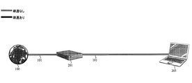
図2のような家庭でインターネット100を利用する場合のネットワーク構成のテンプレートを初期画面として表示する例を考える。ここでは、監視対象のネットワーク101とは、インターネット100とルータ201との間、及びルータ201とパーソナルコンピュータ203との間である。
Consider an example in which a network configuration template when using the Internet 100 at home as shown in FIG. 2 is displayed as an initial screen. Here, the
テンプレート記憶部12は、ネットワーク101の構成を示したテンプレートを記憶するテンプレート記憶手順を行う。テンプレート記憶部12は、図2のネットワーク構成のテンプレートを記憶している。ネットワーク構成は、ノードとノードを結ぶ経路により構成される。図2では、ノードはインターネット100、ルータ201及びパーソナルコンピュータ203である。
The
パケット取得部11は、監視対象のネットワーク101を流れるパケットを取得するパケット取得手順を行う。パケット取得部11は、監視対象のネットワーク101上を流れるパケットを取得する。パケット取得部11としては、図3のようにポートミラーリング機能が付いているスイッチングハブ202を監視対象ネットワーク101に接続し、スイッチングハブ202の監視対象ポート上を流れるパケットを監視用端末が接続されたポートに複製する手段がある。オンサイトでの保守は、図3のようにスイッチングハブ202を監視対象ネットワーク101に接続してパケット取得部11とすることが好ましい。
The
また、他のパケット取得部11としては、図4のようにネットワークを構成する端末であるルータ201にポートミラーリング機能を内蔵しておき、ルータ201を通過するパケットをIPネットワークの故障箇所の可視化装置301にネットワーク経由で転送する手段も考えられる。遠隔での保守は、図4のようにルータ201からパケットを転送するように設定してパケット取得部11とすることが好ましい。
Further, as another
ネットワーク状態演算部13は、パケット取得手順で取得したパケットに含まれる情報に基づき、パケットが疎通している経路の疎通ネットワークを推定し、疎通ネットワークとテンプレート記憶手順が記憶するテンプレートとを比較し、ネットワーク101の各経路についてパケットの疎通の有無を判断するネットワーク状態演算手順を行う。ネットワーク状態演算部13は、パケット取得部11が取得したパケット情報から、ネットワーク101のどの経路にパケットの疎通があるかを計算し、疎通ネットワークを推定する。さらに、ネットワーク状態演算部13は、テンプレート記憶部12が記憶しているネットワーク構成のテンプレートと推定した疎通ネットワークとを突き合わせ、テンプレートのどの部分に疎通があるかを判断する。
The network
出力部14は、テンプレート記憶手順で記憶したテンプレートに、ネットワーク状態演算手順で判断したパケットの疎通の有無をネットワーク101の経路毎に表示して出力する出力手順を行う。出力部14は、ネットワーク状態演算部13の判断結果をもとに、テンプレート記憶部12が記憶するテンプレートのどの部分にパケットの疎通があるかをディスプレイに表示する。図5は、テストパケット送信後の表示例である。図5では、インターネット100とルータ201の経路に疎通があるが、ルータ201とパーソナルコンピュータ203には疎通がないことを示している。
The
このように、IPネットワークの故障箇所の可視化装置301は、パケットの疎通がないノードも表示することができ、経路の配線ミス、断線等の故障原因の推定を容易にする。
As described above, the IP network failure
図6は、テストパケット送信後の他の表示例である。図6では、ルータ201から2つのパーソナルコンピュータ203の一方に対してパケット疎通があったことを示している。このように、IPネットワークの故障箇所の可視化装置301は、ネットワーク状態演算部13が計算した各経路の疎通状況の結果、テンプレートのネットワーク構成に存在しないノードが存在していれば、このノードをテンプレートのネットワーク構成に追加して出力部14に表示させることができる。臨時に接続されているノードやネットワーク設定後に接続されたノードを把握することができる。
FIG. 6 shows another display example after the test packet is transmitted. FIG. 6 shows that there is packet communication from the
(第2の実施形態)
第2の実施形態は、第1の実施形態で説明したIPネットワークの故障箇所の可視化装置301の構成と同様である。第2の実施形態と第1の実施形態との違いは、テンプレート記憶部12は、ネットワーク構成の経路情報のみならず、その経路に疎通があるべきプロトコルの情報が追加されている点である。
(Second Embodiment)
The second embodiment is the same as the configuration of the failure
具体的には、本実施形態のIPネットワークの故障箇所の可視化装置301のテンプレート記憶部12は、テンプレートにネットワーク101の各経路にアプリケーション毎に必要なプロトコル情報を含めて記憶し、ネットワーク状態演算部13は、パケットの疎通の有無をプロトコル毎に判断し、出力部14は、パケットの疎通の有無をプロトコル毎に表示する。
Specifically, the
テンプレート記憶部12は、テンプレート記憶手順で、テンプレートにネットワーク101の各経路にアプリケーション毎に必要なプロトコル情報を含めて記憶する。ネットワーク状態演算部13は、ネットワーク状態演算手順で、パケットの疎通の有無をプロトコル毎に判断する。出力部14は、出力手順で、パケットの疎通の有無をプロトコル毎に表示する。
The
図7は、初期画面の表示例である。左上のタブでアプリケーションの種別を選択する。アプリケーションによって必要なネットワーク構成(経路)とプロトコルが異なる。ここでは、パーソナルコンピュータを用いたWebページの閲覧というアプリケーションの例で説明する。 FIG. 7 is a display example of the initial screen. Select the application type in the upper left tab. The required network configuration (route) and protocol differ depending on the application. Here, an example of an application of browsing a Web page using a personal computer will be described.
Webページの閲覧で、ネットワーク全体として必要なプロトコルの代表例は左上のタブの直下に示されており、その例としてはHTTP、DNS、IP、PPPoE、DHCP、Etherなどがある。画面下部には、各経路に対応するプロトコルが示されている。インターネット100とルータ201間に閲してはPPPoEのプロトコルの疎通が必要であるが、ルータ201とパーソナルコンピュータ203間ではPPPoEのプロトコルの疎通が不要であることが示されている。
Representative examples of protocols necessary for the entire network in browsing a Web page are shown immediately below the upper left tab, and examples thereof include HTTP, DNS, IP, PPPoE, DHCP, and Ether. In the lower part of the screen, protocols corresponding to each route are shown. It is shown that PPPoE protocol communication is necessary between the
図8は、正常性の確認をするためにテストパケット送信後の表示例である。インターネット100とルータ201間は、全てのプロトコルの疎通があるが、ルータ201とパーソナルコンピュータ203間で一部のプロトコルで疎通がない。Etherレイヤーまでは疎通があるので、その上位のレイヤーに故障原因がありそうだという推定が可能となる。
FIG. 8 shows a display example after transmitting a test packet to confirm normality. All protocols communicate between the
(記録媒体の実施例)
本実施形態のIPネットワークの故障箇所の可視化方法は、IPネットワークの故障箇所の可視化方法のプログラム(IPネットワークの故障箇所の可視化プログラム)をコンピュータが実行することで実現することができる。IPネットワークの故障箇所の可視化プログラムは、例えば、記録媒体に格納されて提供される。記録媒体としては、フレキシブルディスク、CD−ROM、DVD等の記録媒体や、半導体メモリ等が例示される。IPネットワークの故障箇所の可視化プログラムは、LAN(Local Area Network)やインターネットを介して提供されてもよい。
(Example of recording medium)
The failure location visualization method of the IP network according to the present embodiment can be realized by causing a computer to execute a failure location visualization method program of an IP network (IP network failure location visualization program). A program for visualizing a failure location of an IP network is provided by being stored in a recording medium, for example. Examples of the recording medium include a recording medium such as a flexible disk, a CD-ROM, and a DVD, a semiconductor memory, and the like. The program for visualizing the failure location of the IP network may be provided via a LAN (Local Area Network) or the Internet.
図9は、記録媒体90に記録されたプログラムを実行するためのコンピュータ300の例を示した図である。コンピュータ300は、フレキシブルディスク、CD−ROM、DVD等の記録媒体90を読み取る記録媒体読み取り装置111と、作業用メモリ(RAM)112と、記録媒体90に記録されたプログラムを記憶するメモリ113と、ディスプレイ114と、入力装置であるマウス115及びキーボード116と、プログラムの実行を制御するCPU117と、データを記憶するハードディスク118と、パケット取得部11として図示しないルータやスイッチングハブに接続するケーブル119と、を備えている。図9では、作業用メモリ112、メモリ113、CPU117及びハードディスク118は筐体に内蔵されるので破線で示している。
FIG. 9 is a diagram illustrating an example of a
コンピュータ300は、記録媒体90が記録媒体読み取り装置111に挿入されると、記録媒体読み取り装置111から記録媒体90に格納されたIPネットワークの故障箇所の可視化プログラムがメモリ113にインストールされる。メモリ113へのインストール完了後、CPU117はIPネットワークの故障箇所の可視化プログラムにアクセス可能になり、当該プログラムによって、コンピュータ300は、本実施形態のIPネットワークの故障箇所の可視化装置として動作することが可能になる。
When the
コンピュータ300が図1のIPネットワークの故障箇所の可視化装置として動作する場合、CPU117がネットワーク状態演算部13として機能する。ハードディスク118がテンプレート記憶部12として機能する。ディスプレイ114が出力部14として機能する。CPU117は図示しないパケット取得部11で取得したパケットを前述のように解析して疎通ネットワークを推定する。さらに、CPU117は、ハードディスク118が記憶しているネットワーク構成のテンプレートと推定した疎通ネットワークとを突き合わせ、テンプレートのどの部分に疎通があるかを判断する。この判断結果は、作業用メモリ112に一時的に保管される。コンピュータ300は、図5、図6、図8で説明したように判断結果をディスプレイ114に表示することができる。
When the
ここでのコンピュータ300は、図9のようなパーソナルコンピュータに限らず、記録媒体読み取り装置111、CPU117を具備しソフトウエアによる処理や制御を行うDVDプレーヤ、ゲーム機、携帯電話などを含む。
The
本発明に係るIPネットワークの故障箇所の可視化装置、IPネットワークの故障箇所の可視化方法及び記録媒体は、家庭内LANや企業内LANに適用することができる。 The IP network failure location visualization apparatus, IP network failure location visualization method, and recording medium according to the present invention can be applied to a home LAN or a corporate LAN.
11:パケット取得部
12:テンプレート記憶部
13:ネットワーク状態演算部
14:出力部
90:記録媒体
100:インターネット
101:ネットワーク
111:記録媒体読み取り装置
112:作業用メモリ
113:メモリ
114:ディスプレイ
115:マウス
116:キーボード
117:CPU
118:ハードディスク
119:ケーブル
201:ルータ
202:スイッチングハブ
203:パーソナルコンピュータ
300:コンピュータ
301:IPネットワークの故障箇所の可視化装置
11: Packet acquisition unit 12: Template storage unit 13: Network state calculation unit 14: Output unit 90: Recording medium 100: Internet 101: Network 111: Recording medium reader 112: Work memory 113: Memory 114: Display 115: Mouse 116: Keyboard 117: CPU
118: Hard disk 119: Cable 201: Router 202: Switching hub 203: Personal computer 300: Computer 301: Visualization device for failure location of IP network
Claims (5)
前記ネットワークの構成を示したテンプレートを記憶するテンプレート記憶部と、
前記パケット取得部が取得した前記パケットに含まれる情報に基づき、パケットが疎通している経路の疎通ネットワークを推定し、前記疎通ネットワークと前記テンプレート記憶部が記憶する前記テンプレートとを比較し、前記ネットワークの各経路についてパケットの疎通の有無を判断するネットワーク状態演算部と、
前記テンプレート記憶部が記憶する前記テンプレートに、前記ネットワーク状態演算部が判断したパケットの疎通の有無を前記ネットワークの経路毎に表示して出力する出力部と、
を備えるIPネットワークの故障箇所の可視化装置。 A packet acquisition unit for acquiring packets flowing through the monitored network;
A template storage unit for storing a template indicating the configuration of the network;
Based on information included in the packet acquired by the packet acquisition unit, a communication network of a route through which a packet is communicated is estimated, the communication network is compared with the template stored in the template storage unit, and the network A network state calculation unit that determines the presence or absence of packet communication for each of the routes,
An output unit for displaying and outputting, for each route of the network, the presence or absence of packet communication determined by the network state calculation unit in the template stored in the template storage unit;
An IP network failure location visualization apparatus comprising:
前記ネットワーク状態演算部は、パケットの疎通の有無をプロトコル毎に判断し、
前記出力部は、パケットの疎通の有無をプロトコル毎に表示すること
を特徴とする請求項1に記載のIPネットワークの故障箇所の可視化装置。 The template storage unit stores the protocol information necessary for each application in each route of the network in the template,
The network state calculation unit determines the presence or absence of packet communication for each protocol,
2. The apparatus for visualizing a fault location of an IP network according to claim 1, wherein the output unit displays the presence / absence of packet communication for each protocol.
前記ネットワークの構成を示したテンプレートを記憶するテンプレート記憶手順と、
前記パケット取得手順で取得した前記パケットに含まれる情報に基づき、パケットが疎通している経路の疎通ネットワークを推定し、前記疎通ネットワークと前記テンプレート記憶手順が記憶する前記テンプレートとを比較し、前記ネットワークの各経路についてパケットの疎通の有無を判断するネットワーク状態演算手順と、
前記テンプレート記憶手順で記憶した前記テンプレートに、前記ネットワーク状態演算手順で判断したパケットの疎通の有無を前記ネットワークの経路毎に表示して出力する出力手順と、
で、IPネットワークの故障箇所を可視化するIPネットワークの故障箇所の可視化方法。 A packet acquisition procedure for acquiring packets flowing through the monitored network;
A template storage procedure for storing a template indicating the configuration of the network;
Based on information included in the packet acquired in the packet acquisition procedure, a communication network of a route through which the packet communicates is estimated, the communication network and the template stored in the template storage procedure are compared, and the network A network state calculation procedure for determining the presence or absence of packet communication for each of the routes,
An output procedure for displaying and outputting the presence / absence of packet communication determined in the network state calculation procedure for each route of the network in the template stored in the template storage procedure;
Then, a method for visualizing the failure location of the IP network for visualizing the failure location of the IP network.
前記ネットワーク状態演算手順では、パケットの疎通の有無をプロトコル毎に判断し、
前記出力手順では、パケットの疎通の有無をプロトコル毎に表示すること
を特徴とする請求項3に記載のIPネットワークの故障箇所の可視化方法。 In the template storing procedure, the template is stored including protocol information necessary for each application in each route of the network.
In the network state calculation procedure, the presence or absence of packet communication is determined for each protocol,
4. The method for visualizing a fault location in an IP network according to claim 3, wherein, in the output procedure, presence / absence of packet communication is displayed for each protocol.
Priority Applications (1)
| Application Number | Priority Date | Filing Date | Title |
|---|---|---|---|
| JP2008241961A JP4787302B2 (en) | 2008-09-22 | 2008-09-22 | IP network failure location visualization apparatus, IP network failure location visualization method, and recording medium |
Applications Claiming Priority (1)
| Application Number | Priority Date | Filing Date | Title |
|---|---|---|---|
| JP2008241961A JP4787302B2 (en) | 2008-09-22 | 2008-09-22 | IP network failure location visualization apparatus, IP network failure location visualization method, and recording medium |
Publications (2)
| Publication Number | Publication Date |
|---|---|
| JP2010074688A true JP2010074688A (en) | 2010-04-02 |
| JP4787302B2 JP4787302B2 (en) | 2011-10-05 |
Family
ID=42206022
Family Applications (1)
| Application Number | Title | Priority Date | Filing Date |
|---|---|---|---|
| JP2008241961A Active JP4787302B2 (en) | 2008-09-22 | 2008-09-22 | IP network failure location visualization apparatus, IP network failure location visualization method, and recording medium |
Country Status (1)
| Country | Link |
|---|---|
| JP (1) | JP4787302B2 (en) |
Cited By (2)
| Publication number | Priority date | Publication date | Assignee | Title |
|---|---|---|---|---|
| CN111970203A (en) * | 2020-08-03 | 2020-11-20 | 江苏创通电子股份有限公司 | Method for realizing port mirror image based on router |
| CN114650167A (en) * | 2022-02-08 | 2022-06-21 | 联想(北京)有限公司 | Abnormity detection method, device, equipment and computer readable storage medium |
Citations (4)
| Publication number | Priority date | Publication date | Assignee | Title |
|---|---|---|---|---|
| JP2001186127A (en) * | 1999-12-24 | 2001-07-06 | Nippon Telegr & Teleph Corp <Ntt> | Understanding state measurement system, understanding state measurement method and storage medium |
| JP2005033391A (en) * | 2003-07-10 | 2005-02-03 | Hitachi Ltd | Network monitoring apparatus using correlation of request and its response |
| JP2006050137A (en) * | 2004-08-03 | 2006-02-16 | Kddi Corp | Method and program for diagnosing network connection, and its storage medium |
| JP2008172291A (en) * | 2007-01-05 | 2008-07-24 | Fujitsu Ltd | Path search apparatus, path search program, path search method and path search system |
-
2008
- 2008-09-22 JP JP2008241961A patent/JP4787302B2/en active Active
Patent Citations (4)
| Publication number | Priority date | Publication date | Assignee | Title |
|---|---|---|---|---|
| JP2001186127A (en) * | 1999-12-24 | 2001-07-06 | Nippon Telegr & Teleph Corp <Ntt> | Understanding state measurement system, understanding state measurement method and storage medium |
| JP2005033391A (en) * | 2003-07-10 | 2005-02-03 | Hitachi Ltd | Network monitoring apparatus using correlation of request and its response |
| JP2006050137A (en) * | 2004-08-03 | 2006-02-16 | Kddi Corp | Method and program for diagnosing network connection, and its storage medium |
| JP2008172291A (en) * | 2007-01-05 | 2008-07-24 | Fujitsu Ltd | Path search apparatus, path search program, path search method and path search system |
Cited By (3)
| Publication number | Priority date | Publication date | Assignee | Title |
|---|---|---|---|---|
| CN111970203A (en) * | 2020-08-03 | 2020-11-20 | 江苏创通电子股份有限公司 | Method for realizing port mirror image based on router |
| CN114650167A (en) * | 2022-02-08 | 2022-06-21 | 联想(北京)有限公司 | Abnormity detection method, device, equipment and computer readable storage medium |
| CN114650167B (en) * | 2022-02-08 | 2023-06-27 | 联想(北京)有限公司 | Abnormality detection method, abnormality detection device, abnormality detection equipment and computer-readable storage medium |
Also Published As
| Publication number | Publication date |
|---|---|
| JP4787302B2 (en) | 2011-10-05 |
Similar Documents
| Publication | Publication Date | Title |
|---|---|---|
| US20070014233A1 (en) | Fault management apparatus and method for identifying cause of fault in communication network | |
| US20080181136A1 (en) | Medium having recorded therein network configuration verification program, network configuration verification method, and network configuration verification apparatus | |
| JP4973734B2 (en) | Network monitoring system, route extraction method, program, and computer-readable recording medium recording the program | |
| JP6677251B2 (en) | Network verification device, network verification method, and program | |
| US9467332B2 (en) | Node failure detection for distributed linear protection | |
| JP2007208633A (en) | Device, method and program for designing network | |
| JP4754018B2 (en) | Route data collection method, layer 2 device, carrier network device, and route data collection device | |
| JP4787302B2 (en) | IP network failure location visualization apparatus, IP network failure location visualization method, and recording medium | |
| JP5035219B2 (en) | Communication path detection method, communication path detection program, and communication path detection apparatus | |
| US8750299B2 (en) | Multicast tree discovery using 802.1ag | |
| CN101505241A (en) | Method and apparatus for generating test instances | |
| JP4147430B2 (en) | Programmable controller system | |
| CN109787865B (en) | Method, system, switch and storage medium for verifying upgrading condition | |
| TW201517556A (en) | Network status visualization systems and methods | |
| JP4621694B2 (en) | Monitoring device and monitoring method | |
| JP4912435B2 (en) | IP network failure location visualization apparatus, IP network failure location visualization method, IP network failure location visualization program | |
| JP4773978B2 (en) | Route search device, route search program, route search method, and route search system | |
| JP6246885B1 (en) | Route analysis processing apparatus and route analysis processing program | |
| Yamada et al. | Developing network configuration management database system and its application—data federation for network management | |
| JP3725146B2 (en) | Communication network management apparatus and communication network communication confirmation test method | |
| JP2015012317A (en) | Route identifying device, route identifying method, and program | |
| WO2021001867A1 (en) | Exchange management device, exchange management method, and program | |
| JP2011097226A (en) | Network monitoring system | |
| JP2017005449A (en) | Network verification device, network verification method and program | |
| JP5075146B2 (en) | Congestion impact level evaluation apparatus, congestion impact level evaluation method, and program thereof |
Legal Events
| Date | Code | Title | Description |
|---|---|---|---|
| A977 | Report on retrieval |
Free format text: JAPANESE INTERMEDIATE CODE: A971007 Effective date: 20101115 |
|
| A131 | Notification of reasons for refusal |
Free format text: JAPANESE INTERMEDIATE CODE: A131 Effective date: 20101124 |
|
| A521 | Written amendment |
Free format text: JAPANESE INTERMEDIATE CODE: A523 Effective date: 20110113 |
|
| A131 | Notification of reasons for refusal |
Free format text: JAPANESE INTERMEDIATE CODE: A131 Effective date: 20110329 |
|
| A521 | Written amendment |
Free format text: JAPANESE INTERMEDIATE CODE: A523 Effective date: 20110509 |
|
| TRDD | Decision of grant or rejection written | ||
| A01 | Written decision to grant a patent or to grant a registration (utility model) |
Free format text: JAPANESE INTERMEDIATE CODE: A01 Effective date: 20110712 |
|
| A01 | Written decision to grant a patent or to grant a registration (utility model) |
Free format text: JAPANESE INTERMEDIATE CODE: A01 |
|
| A61 | First payment of annual fees (during grant procedure) |
Free format text: JAPANESE INTERMEDIATE CODE: A61 Effective date: 20110714 |
|
| R150 | Certificate of patent or registration of utility model |
Ref document number: 4787302 Country of ref document: JP Free format text: JAPANESE INTERMEDIATE CODE: R150 Free format text: JAPANESE INTERMEDIATE CODE: R150 |
|
| FPAY | Renewal fee payment (event date is renewal date of database) |
Free format text: PAYMENT UNTIL: 20140722 Year of fee payment: 3 |
|
| S531 | Written request for registration of change of domicile |
Free format text: JAPANESE INTERMEDIATE CODE: R313531 |
|
| R350 | Written notification of registration of transfer |
Free format text: JAPANESE INTERMEDIATE CODE: R350 |