JP2010073115A - Fingerprint-inputting device, method and program - Google Patents
Fingerprint-inputting device, method and program Download PDFInfo
- Publication number
- JP2010073115A JP2010073115A JP2008242598A JP2008242598A JP2010073115A JP 2010073115 A JP2010073115 A JP 2010073115A JP 2008242598 A JP2008242598 A JP 2008242598A JP 2008242598 A JP2008242598 A JP 2008242598A JP 2010073115 A JP2010073115 A JP 2010073115A
- Authority
- JP
- Japan
- Prior art keywords
- ridge
- frame image
- point
- direction vector
- fingerprint
- Prior art date
- Legal status (The legal status is an assumption and is not a legal conclusion. Google has not performed a legal analysis and makes no representation as to the accuracy of the status listed.)
- Granted
Links
Images


Abstract
Description
本発明は、複数ラインからなるライン指紋センサー上で指を掃引(スイープ)して指紋画像を入力する装置、その方法及びそのプログラムに関する。 The present invention relates to an apparatus for inputting a fingerprint image by sweeping a finger on a line fingerprint sensor composed of a plurality of lines, a method thereof, and a program thereof.
近年、パスワードによるユーザ認証とは別に、個人の身体的特徴に基づいてユーザ認証を行う生体認証がIT関連等の様々な分野で利用されている。 In recent years, apart from user authentication using passwords, biometric authentication that performs user authentication based on individual physical characteristics has been used in various fields such as IT.
中でも、指紋によって個人を特定する技術は、網膜又は虹彩等を読み取る他の生体認証技術に比較して簡便であることから、広く用いられている。 Among these, a technique for identifying an individual using a fingerprint is widely used because it is simpler than other biometric authentication techniques for reading the retina or iris.
そのため、特許文献1〜4では、ライン指紋センサー上で指を掃引(スイープ)して指紋画像を入力する発明が開示されている。
しかしながら、特許文献1〜4に開示されている発明では、取得される1フレーム画像の全画素から指領域を判断していた。この方法では、1フレーム画像全体から指領域を抽出しなければならないため、処理に時間がかかるという問題点があった。
However, in the inventions disclosed in
指紋入力処理が遅いということは、高速なスイープに対応することができず、指紋入力の使い勝手が損なわれてしまう。 The fact that the fingerprint input processing is slow cannot cope with a high-speed sweep, and the usability of fingerprint input is impaired.
本発明は上記に鑑みてなされたもので、高速なスイープに対応することができる指紋入力装置、その方法及びそのプログラムを提供することを目的とする。 The present invention has been made in view of the above, and an object of the present invention is to provide a fingerprint input device, a method thereof, and a program thereof that can cope with a high-speed sweep.
上述の課題を解決するため、本発明に係る指紋入力装置は、短冊状の画像を読み取るライン指紋センサー上を掃引される指の指紋を連続する複数の短冊状画像として読み取り、該複数の短冊状画像を合成することで前記指紋の画像データを取得する指紋入力装置において、RAM(Random Access Memory)、ROM(Read Only Memory)及びCPU(Central Processing Unit)を有する中央処理装置と、RAM又はハードディスクを有する記憶装置と、を備え、前記中央処理装置は、前記短冊状画像の1つである1フレーム画像について、前記1フレーム画像の下辺の左端から右方向へ、該下辺の右端から左方向へ、前記1フレーム画像の上辺の左端から右方向へ、該上辺の右端から左方向へ、該指紋の紋様で盛り上がっている部分である隆線をそれぞれ探索し、前記下辺の左端から右方向の探索で最初に発見した隆線上の点である左下端隆線位置を始点とし、前記上辺の左端から右方向の探索で最初に発見した隆線上の点である左上端隆線位置を終点とする左端隆線方向ベクトルと、前記下辺の右端から左方向の探索で最初に発見した隆線上の点である右下端隆線位置を始点とし、前記上辺の右端から左方向の探索で最初に発見した隆線上の点である右上端隆線位置を終点とする右端隆線方向ベクトルと、を設定し、前記1フレーム画像に連続する新たな1フレーム画像の底辺上にある前記左上端隆線位置とX座標が同一の点を始点として前記左端隆線方向ベクトルの延長線を設定し、前記新たな1フレーム画像の底辺上にある前記右上端隆線位置とX座標が同一の点を始点として前記右端隆線方向ベクトルの延長線を設定し、前記左端隆線方向ベクトルの延長線と、前記右端隆線方向ベクトルの延長線と、前記新たな1フレーム画像の上辺と、前記新たな1フレーム画像の下辺とで囲まれる領域を設定し、該領域に限定して指紋抽出処理を行うことを特徴とする。 In order to solve the above-described problems, a fingerprint input device according to the present invention reads a fingerprint of a finger swept on a line fingerprint sensor that reads a strip-shaped image as a plurality of continuous strip-shaped images, and the plurality of strip-shaped images. In a fingerprint input device that acquires image data of a fingerprint by combining images, a central processing unit having a RAM (Random Access Memory), a ROM (Read Only Memory) and a CPU (Central Processing Unit), and a RAM or hard disk The central processing unit, with respect to one frame image that is one of the strip-shaped images, from the left end of the lower side of the one frame image to the right direction, and from the right end of the lower side to the left direction, Search for ridges that are raised with the fingerprint pattern from the left edge of the upper side of the one-frame image to the right and from the right edge of the upper side to the left. Starting from the position of the lower left ridge that is the first point on the ridge found in the right search from the left end of the lower side, the upper left that is the point on the ridge that was first found in the right search from the left end of the upper side The left edge ridge direction vector with the edge ridge position as the end point, and the right lower edge ridge position that is the first point on the ridge found in the leftward search from the right edge of the lower edge, and the left edge from the right edge of the upper edge. A right edge ridge direction vector whose end point is an upper right edge ridge position, which is a point on the ridge first discovered by the direction search, is set on the bottom of a new one frame image continuous to the one frame image. An extension line of the left edge ridge direction vector is set starting from a point having the same X coordinate as the certain left upper edge ridge position, and the upper right edge ridge position and X coordinate on the bottom of the new one-frame image are set. Starting from the same point, the right edge ridge direction An extension line of Kutor is set, and an extension line of the left edge ridge direction vector, an extension line of the right edge ridge direction vector, an upper side of the new one frame image, and a lower side of the new one frame image A region to be surrounded is set, and fingerprint extraction processing is performed only on the region.
上述の課題を解決するため、本発明に係る指紋入力方法は、短冊状の画像を読み取るライン指紋センサー上を掃引される指の指紋を連続する複数の短冊状画像として読み取り、該複数の短冊状画像を合成することで前記指紋の画像データを取得する指紋入力方法において、RAM(Random Access Memory)、ROM(Read Only Memory)及びCPU(Central Processing Unit)を有する中央処理装置での処理の手順と、RAM又はハードディスクを有する記憶装置での処理の手順と、を有し、前記中央処理装置での処理の手順は、前記短冊状画像の1つである1フレーム画像について、前記1フレーム画像の下辺の左端から右方向へ、該下辺の右端から左方向へ、前記1フレーム画像の上辺の左端から右方向へ、該上辺の右端から左方向へ、該指紋の紋様で盛り上がっている部分である隆線をそれぞれ探索する手順と、前記下辺の左端から右方向の探索で最初に発見した隆線上の点である左下端隆線位置を始点とし、前記上辺の左端から右方向の探索で最初に発見した隆線上の点である左上端隆線位置を終点とする左端隆線方向ベクトルと、前記下辺の右端から左方向の探索で最初に発見した隆線上の点である右下端隆線位置を始点とし、前記上辺の右端から左方向の探索で最初に発見した隆線上の点である右上端隆線位置を終点とする右端隆線方向ベクトルと、を設定する手順と、前記1フレーム画像に連続する新たな1フレーム画像の底辺上にある前記左上端隆線位置とX座標が同一の点を始点として前記左端隆線方向ベクトルの延長線を設定する手順と、前記新たな1フレーム画像の底辺上にある前記右上端隆線位置とX座標が同一の点を始点として前記右端隆線方向ベクトルの延長線を設定する手順と、前記左端隆線方向ベクトルの延長線と、前記右端隆線方向ベクトルの延長線と、前記新たな1フレーム画像の上辺と、前記新たな1フレーム画像の下辺とで囲まれる領域を設定する手順と、該領域に限定して指紋抽出処理を行う手順と、を備えることを特徴とする。 In order to solve the above-mentioned problems, a fingerprint input method according to the present invention reads a fingerprint of a finger swept on a line fingerprint sensor that reads a strip-shaped image, and reads the plurality of strip-shaped images as a plurality of continuous strip-shaped images. In a fingerprint input method for acquiring image data of a fingerprint by combining images, a processing procedure in a central processing unit having a RAM (Random Access Memory), a ROM (Read Only Memory), and a CPU (Central Processing Unit) A processing procedure in a storage device having a RAM or a hard disk, and the processing procedure in the central processing unit is based on a lower side of the one-frame image with respect to one frame image that is one of the strip-shaped images. The left and right edges of the one-frame image are printed in the right direction from the left edge to the right, the left edge of the upper side of the one-frame image is moved to the right, and the right edge of the upper side is moved to the left. Starting from the left lower edge ridge position, which is the point on the ridge first found in the search from the left edge of the lower side to the right, starting from the left lower edge ridge position, starting from the left edge of the upper side The left edge ridge direction vector whose end point is the upper left ridge position, which is the first point on the ridge found in the right direction search, and the point on the ridge first found in the left direction search from the right end of the lower side. A procedure for setting a right edge ridge direction vector starting from a certain right lower edge ridge position and having an upper right edge ridge position as an end point, which is a point on the ridge first found in the left direction search from the right edge of the upper side. A procedure for setting an extension line of the left edge ridge direction vector starting from a point having the same X coordinate as the left upper edge ridge position on the bottom of a new one frame image continuous to the one frame image; On the bottom of the new one-frame image A procedure for setting an extension line of the right end ridge direction vector starting from a point having the same X coordinate as the upper right end ridge position, an extension line of the left end ridge direction vector, and an extension of the right end ridge direction vector A procedure for setting an area surrounded by a line, an upper side of the new one-frame image, and a lower side of the new one-frame image, and a procedure for performing a fingerprint extraction process limited to the area. Features.
上述の課題を解決するため、本発明に係る指紋入力プログラムは、短冊状の画像を読み取るライン指紋センサー上を掃引される指の指紋を連続する複数の短冊状画像として読み取り、該複数の短冊状画像を合成することで前記指紋の画像データを取得する指紋入力プログラムにおいて、RAM(Random Access Memory)、ROM(Read Only Memory)及びCPU(Central Processing Unit)を有する中央処理装置での処理と、RAM又はハードディスクを有する記憶装置での処理と、を有し、前記中央処理装置での処理は、前記短冊状画像の1つである1フレーム画像について、前記1フレーム画像の下辺の左端から右方向へ、該下辺の右端から左方向へ、前記1フレーム画像の上辺の左端から右方向へ、該上辺の右端から左方向へ、該指紋の紋様で盛り上がっている部分である隆線をそれぞれ探索する処理と、前記下辺の左端から右方向の探索で最初に発見した隆線上の点である左下端隆線位置を始点とし、前記上辺の左端から右方向の探索で最初に発見した隆線上の点である左上端隆線位置を終点とする左端隆線方向ベクトルと、前記下辺の右端から左方向の探索で最初に発見した隆線上の点である右下端隆線位置を始点とし、前記上辺の右端から左方向の探索で最初に発見した隆線上の点である右上端隆線位置を終点とする右端隆線方向ベクトルと、を設定する処理と、前記1フレーム画像に連続する新たな1フレーム画像の底辺上にある前記左上端隆線位置とX座標が同一の点を始点として前記左端隆線方向ベクトルの延長線を設定する処理と、前記新たな1フレーム画像の底辺上にある前記右上端隆線位置とX座標が同一の点を始点として前記右端隆線方向ベクトルの延長線を設定する処理と、前記左端隆線方向ベクトルの延長線と、前記右端隆線方向ベクトルの延長線と、前記新たな1フレーム画像の上辺と、前記新たな1フレーム画像の下辺とで囲まれる領域を設定する処理と、該領域に限定して指紋抽出処理を行う処理と、をコンピュータに実行させることを特徴とする。 In order to solve the above-described problems, a fingerprint input program according to the present invention reads a fingerprint of a finger swept on a line fingerprint sensor that reads a strip-shaped image as a plurality of continuous strip-shaped images, and the plurality of strip-shaped images In a fingerprint input program for acquiring image data of a fingerprint by synthesizing an image, processing in a central processing unit having a RAM (Random Access Memory), a ROM (Read Only Memory) and a CPU (Central Processing Unit), and a RAM Or processing in a storage device having a hard disk, and the processing in the central processing unit is performed in the right direction from the left end of the lower side of the one frame image with respect to one frame image which is one of the strip-like images. The fingerprint pattern swells from the right edge of the lower edge to the left, from the left edge of the upper edge of the one-frame image to the right, and from the right edge of the upper edge to the left. Each of the ridges that are located on the left side of the lower side, and a left ridge position that is a point on the ridge that is first found in the search from the left side of the lower side to the right side. Left end ridge direction vector whose end point is the upper left ridge position, which is the first point on the ridge found in the search, and lower right end, which is the first point on the ridge found in the left direction search from the right end of the lower side A process for setting a right edge ridge direction vector having a ridge position as a start point, and an upper right edge ridge position that is a point on the ridge first found in a leftward search from the right edge of the upper side, and an end point; and A process of setting an extension line of the left edge ridge direction vector starting from a point having the same X coordinate as the left upper edge ridge position on the bottom of a new one frame image continuous to the one frame image; The right above the bottom of one frame image A process of setting an extension line of the right edge ridge direction vector starting from a point having the same X coordinate as the upper edge ridge position; an extension line of the left edge ridge direction vector; an extension line of the right edge ridge direction vector; , Causing a computer to execute a process of setting an area surrounded by an upper side of the new one-frame image and a lower side of the new one-frame image, and a process of performing a fingerprint extraction process limited to the area It is characterized by.
本発明によれば、新たな1フレーム画像上で、その直前の1フレーム画像上の隆線上の点からそれぞれ設定した左端隆線方向ベクトル及び右端隆線方向ベクトルの延長線と、新たな1フレーム画像の上辺と、前記新たな1フレーム画像の下辺とで囲まれる領域を設定し、この領域に限定して指紋抽出処理を行うことで、フレーム画像全領域から指が存在すると推測される領域のみを処理することができ、フレーム画像全領域を処理する場合と比較して、1フレームに対する計算量の削減が行え、より高速なスイープに対応することができる指紋入力装置、その方法及びそのプログラムを提供することができる。 According to the present invention, on the new one frame image, the extension line of the left edge ridge direction vector and the right edge ridge direction vector respectively set from the points on the ridge on the immediately preceding one frame image, and the new one frame By setting a region surrounded by the upper side of the image and the lower side of the new one-frame image and performing fingerprint extraction processing only on this region, only the region where it is assumed that a finger is present from the entire region of the frame image Compared with the case where the entire frame image region is processed, the amount of calculation for one frame can be reduced, and a fingerprint input device, method and program thereof that can cope with a higher-speed sweep Can be provided.
次に、本発明の実施の形態について図面を参照して詳細に説明する。
[第1実施形態]
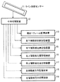
図1は、本発明における第1の実施の形態に係る指紋入力装置の構成図である。
Next, embodiments of the present invention will be described in detail with reference to the drawings.
[First Embodiment]
FIG. 1 is a configuration diagram of a fingerprint input device according to a first embodiment of the present invention.
この図1では、本実施の形態に係る指紋入力装置は、ライン指紋センサー上をスイープ(掃引)される指の指紋を連続する複数の短冊状画像として読み取り、該複数の短冊状画像を合成することで前記指紋の画像データを取得する指紋入力装置であって、短冊状の画像を読み取るライン指紋センサー11と、RAM(Random Access Memory)、ROM(Read Only Memory)及びCPU(Central Processing Unit)で構成される中央処理装置12と、現在の1フレーム画像を格納する現在1フレーム記憶装置13と、直前の1フレーム画像の左下端の隆線位置を格納する左下端隆線位置記憶装置14と、直前フレーム画像の右下端の隆線位置を格納する右下端隆線位置記憶装置15と、直前フレーム画像の左上端の隆線位置を格納する左上端隆線位置記憶装置16と、直前フレーム画像の右上端の隆線位置を格納する右上端隆線位置記憶装置17と、直前フレーム画像の左端隆線方向を格納する左端隆線方向記憶装置18と、直前フレーム画像の右端隆線方向を格納する右端隆線方向記憶装置19と、を備える。
In FIG. 1, the fingerprint input device according to the present embodiment reads a fingerprint of a finger swept over the line fingerprint sensor as a plurality of continuous strip images, and synthesizes the plurality of strip images. A fingerprint input device for acquiring image data of the fingerprint by a line fingerprint sensor 11 for reading a strip-shaped image, a RAM (Random Access Memory), a ROM (Read Only Memory), and a CPU (Central Processing Unit). A
現在1フレーム記憶装置13、左下端隆線位置記憶装置14、右下端隆線位置記憶装置15、左上端隆線位置記憶装置16、右上端隆線位置記憶装置17、左端隆線方向記憶装置18及び右端隆線方向記憶装置19は、全て情報記憶媒体であるRAM(Random Access Memory)又はハードディスクで構成される記憶装置であり、中央処理装置12とは、LAN、RS232Cシリアル通信又はバス信号線等で接続される。
Current one-
現在1フレーム記憶装置13の情報記憶媒体の容量は、ライン指紋センサー11から取得される画像が格納できる容量を必要とする。
Currently, the capacity of the information storage medium of the one-
左下端隆線位置記憶装置14、右下端隆線位置記憶装置15、左上端隆線位置記憶装置16及び右上端隆線位置記憶装置17の情報記憶媒体の容量は、中央処理装置12で計算された、1フレーム画像上の任意の位置が記憶できる容量を必要とする。
The capacity of the information storage medium of the lower left ridge
左端隆線方向記憶装置18及び右端隆線方向記憶装置19の情報記憶媒体の容量は、中央処理装置12で計算された左右端隆線方向が記憶できる容量を必要とする。
The capacity of the information storage medium of the left end ridge
本実施の形態に係る指紋入力装置へ指紋を入力するには、図2のように入力指22をライン指紋センサー11と垂直に交差するよう横向きに置き、入力指22でライン指紋センサー11をこするように図中矢印方向(掃引方向23)へ掃引する。これによって、ライン指紋センサー11から図3に示すような指紋画像の横長な短冊状画像が連続して取得される。 In order to input a fingerprint to the fingerprint input device according to the present embodiment, the input finger 22 is placed sideways so as to intersect the line fingerprint sensor 11 vertically as shown in FIG. As shown, the sweep is performed in the direction of the arrow (sweep direction 23). Thereby, a horizontally long strip-like image of the fingerprint image as shown in FIG. 3 is continuously acquired from the line fingerprint sensor 11.
次に、図1のブロック図と、図4乃至図11の図と、を参照し、本実施の形態に係る指紋入力装置の動作を説明する。 Next, the operation of the fingerprint input device according to the present embodiment will be described with reference to the block diagram of FIG. 1 and the diagrams of FIGS. 4 to 11.
指紋入力が開始されると、図1の中央処理装置12は、ライン指紋センサー11から図3に示すような短冊状画像の1フレーム画像(フレーム画像A)を取得し、その画像を現在1フレーム記憶装置13へ格納する。この図3に描かれている曲線は、指紋の紋様で盛り上がっている部分である「隆線」である。
When the fingerprint input is started, the
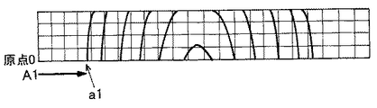
次に、中央処理装置12は、図4に示すように、現在1フレーム記憶装置13中のフレーム画像A中下辺の左端からA1の方向(右方向)へ、最初の隆線を画素値の違い等から探索する。そして、発見した隆線の点を左下端隆線位置a1とする。
Next, as shown in FIG. 4, the
この点a1の座標(Xa1,Ya1)を、左下端隆線位置記憶装置14へ格納する。このとき、座標は、1フレーム画像の下辺の左端を原点Oとし、右方向画素数をX座標、上方向画素数をY座標とした座標値から得られる。
The coordinates (Xa1, Ya1) of this point a1 are stored in the left bottom ridge
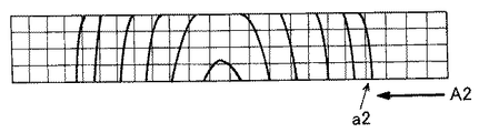
同様に、図5に示すように、1フレーム画像中下辺の右端からA2の方向(左方向)へ、最初の隆線を探索する。そして、発見した隆線の点を右下端隆線位置a2とし、その座標(Xa2,Ya2)を、右下端隆線位置記憶装置15へ格納する。
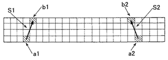
さらに、中央処理装置12は、現在1フレーム記憶装置13中の1フレーム画像を模式的に描いた図6に示すように、1フレーム画像中上辺の左端からB1の方向(右方向)へ、最初の隆線を探索する。そして、発見した隆線の点を左上端隆線位置b1とし、その座標(Xb1,Yb1)を、左上端隆線位置記憶装置16へ格納する。
Similarly, as shown in FIG. 5, the first ridge is searched in the direction A2 (left direction) from the right end of the lower side in one frame image. Then, the found ridge point is set as the lower right ridge position a2, and the coordinates (Xa2, Ya2) are stored in the lower right ridge
Further, as shown in FIG. 6, which schematically depicts one frame image in the current one
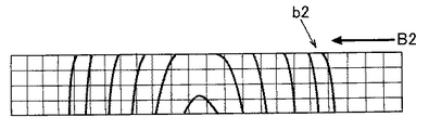
同様に、図7に示すように、1フレーム画像中上辺の右端からB2の方向(左方向)へ、最初の隆線を探索する。そして、発見した隆線の点を右上端隆線位置b2とし、その座標(Xb2,Yb2)を、右上端隆線位置記憶装置17へ格納する。
Similarly, as shown in FIG. 7, the first ridge is searched in the direction B2 (left direction) from the right end of the upper side in one frame image. The found ridge point is set as the upper right ridge position b2, and the coordinates (Xb2, Yb2) are stored in the upper right ridge
算出された点a1、a2、b1、b2を1フレーム画像上に、同時に示した図が、図8である。 FIG. 8 shows the calculated points a1, a2, b1, and b2 on one frame image at the same time.
次に、中央処理装置12は、点a1を始点、点b1を終点とする左端隆線方向ベクトルであるベクトルS1の成分を次式で計算し、左端隆線方向記憶装置18へ格納する。
Next, the
S1=(Xb1−Xa1, Yb1−Ya1)
同様に、点a2を始点とし、点b2を終点とする右端隆線方向ベクトルであるベクトルS2の成分も次式で計算し、右端隆線方向記憶装置19へ格納する。
S1 = (Xb1-Xa1, Yb1-Ya1)
Similarly, the component of the vector S2, which is the right edge ridge direction vector starting from the point a2 and ending at the point b2, is also calculated by the following equation and stored in the right edge ridge
S2=(Xb2−Xa2, Yb2−Ya2)
ベクトルS1とベクトルS2を1フレーム画像上へ太矢印として示した図が、図9である。
S2 = (Xb2-Xa2, Yb2-Ya2)
FIG. 9 shows the vector S1 and the vector S2 as thick arrows on one frame image.
次に、中央処理装置12は、ライン指紋センサー11から次の新しい1フレーム画像(フレーム画像B)を取得し、その画像を現在1フレーム記憶装置13へ格納する。
Next, the
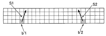
1フレーム画像に連続する新たな1フレーム画像(フレーム画像B)の底辺上に、前述までに算出された点b1、b2から、次式で表されるように、左上端隆線位置b1とX座標が同一の点であるb’1及び右上端隆線位置b2とX座標が同一の点であるb’2を設定し、更に点b’1を始点として左端隆線方向ベクトルであるベクトルS1及び点b’2を始点として右端隆線方向ベクトルであるベクトルS2を、それぞれ図10のように設定する。なお、この場合、原点Oは新たな1フレーム画像の下辺の左端となる。 From the points b1 and b2 calculated so far on the bottom of a new one-frame image (frame image B) continuous to the one-frame image, as represented by the following equation, the upper left ridge position b1 and X B′1 that is the same coordinate and b′2 that is the same as the right upper edge ridge position b2 and the X coordinate are set, and a vector S1 that is a left edge ridge direction vector starting from the point b′1. And the vector S2 which is a right edge ridge direction vector is set as shown in FIG. 10 starting from the point b′2. In this case, the origin O is the left end of the lower side of the new one-frame image.
b’1=(Xb1,0)
b’2=(Xb2,0)
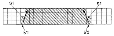
点b’1と、点b’2と、点b’1を始点とするベクトルS1の延長線が上辺と交わる点と、点b’2を始点とするベクトルS2の延長線が上辺と交わる点と、で囲まれる図11の斜線領域を設定し、この限られた領域に対して、指紋抽出処理を行う。
b′1 = (Xb1, 0)
b′2 = (Xb2, 0)
Point b′1, point b′2, a point where an extension line of vector S1 starting from point b′1 intersects with the upper side, and a point where an extension line of vector S2 starting from point b′2 intersects the upper side 11 is set, and the fingerprint extraction process is performed on the limited area.
この領域は、左端隆線方向ベクトルの延長線と、右端隆線方向ベクトルの延長線と、新たな1フレーム画像の上辺と、新たな1フレーム画像の下辺とで囲まれる領域でもある。 This area is also an area surrounded by the extension line of the left end ridge direction vector, the extension line of the right end ridge direction vector, the upper side of the new one-frame image, and the lower side of the new one-frame image.
更に中央処理装置は、連続する複数の短冊状画像、すなわち連続して存在するそれぞれの1フレーム画像について、前述のように領域を設定し、この領域に限定して前記指紋抽出処理を行う。 Further, the central processing unit sets an area as described above for a plurality of continuous strip-shaped images, that is, each one frame image that exists continuously, and performs the fingerprint extraction process only on this area.
これまでに述べたように、前回の1フレーム画像から得られる左上端隆線位置、右上端隆線位置、左端隆線方向ベクトル及び右端隆線方向ベクトルから、次に取得される1フレーム画像で指が存在すると考えられる領域を推定することを繰り返すことによって、指紋抽出処理を行うべき領域を制限することができ、処理時間の短縮が可能となる。
[第2実施形態]
本発明に係る第2の実施形態について説明する。本発明では、左右端隆線方向ベクトルを直線として算出したが、隆線の曲率を考慮に入れて、曲線で構成しても良い。
As described so far, the next one frame image obtained from the upper left ridge position, the upper right edge ridge position, the left edge ridge direction vector and the right edge ridge direction vector obtained from the previous one frame image By repeatedly estimating the area where the finger is considered to be present, the area where the fingerprint extraction process should be performed can be limited, and the processing time can be shortened.
[Second Embodiment]
A second embodiment according to the present invention will be described. In the present invention, the ridge direction vector at the left and right ends is calculated as a straight line. However, the ridge direction vector may be configured by a curve in consideration of the curvature of the ridge.
また、本発明では、左上端隆線位置、右上端隆線位置、左端隆線方向ベクトル、右端隆線方向ベクトルで囲まれた領域を、次回フレーム画像の指が存在すると推測される領域としたが、指が横方向へ動いてしまうことを考え、領域の横幅を少なくとも1画素拡張し、指領域を推定しても良い。 Further, in the present invention, the region surrounded by the upper left ridge position, the upper right ridge position, the left ridge direction vector, and the right ridge direction vector is set as an area in which the finger of the next frame image is estimated to exist. However, considering that the finger moves in the horizontal direction, the finger region may be estimated by extending the horizontal width of the region by at least one pixel.
本発明は、生体認証において利用される指紋入力装置に利用することができる。 The present invention can be used for a fingerprint input device used in biometric authentication.
11 ライン指紋センサー
12 中央処理装置
13 現在1フレーム記憶装置
14 左下端隆線位置記憶装置
15 右下端隆線位置記憶装置
16 左上端隆線位置記憶装置
17 右上端隆線位置記憶装置
18 左端隆線方向記憶装置
19 右端隆線方向記憶装置
22 入力指
23 掃引方向
11
Claims (18)
RAM(Random Access Memory)、ROM(Read Only Memory)及びCPU(Central Processing Unit)を有する中央処理装置と、RAM又はハードディスクを有する記憶装置と、を備え、
前記中央処理装置は、
前記短冊状画像の1つである1フレーム画像について、前記1フレーム画像の下辺の左端から右方向へ、該下辺の右端から左方向へ、前記1フレーム画像の上辺の左端から右方向へ、該上辺の右端から左方向へ、該指紋の紋様で盛り上がっている部分である隆線をそれぞれ探索し、
前記下辺の左端から右方向の探索で最初に発見した隆線上の点である左下端隆線位置を始点とし、前記上辺の左端から右方向の探索で最初に発見した隆線上の点である左上端隆線位置を終点とする左端隆線方向ベクトルと、前記下辺の右端から左方向の探索で最初に発見した隆線上の点である右下端隆線位置を始点とし、前記上辺の右端から左方向の探索で最初に発見した隆線上の点である右上端隆線位置を終点とする右端隆線方向ベクトルと、を設定し、
前記1フレーム画像に連続する新たな1フレーム画像の底辺上にある前記左上端隆線位置とX座標が同一の点を始点として前記左端隆線方向ベクトルの延長線を設定し、
前記新たな1フレーム画像の底辺上にある前記右上端隆線位置とX座標が同一の点を始点として前記右端隆線方向ベクトルの延長線を設定し、
前記左端隆線方向ベクトルの延長線と、前記右端隆線方向ベクトルの延長線と、前記新たな1フレーム画像の上辺と、前記新たな1フレーム画像の下辺とで囲まれる領域を設定し、
該領域に限定して指紋抽出処理を行うことを特徴とする指紋入力装置。 A fingerprint input device that reads a fingerprint of a finger scanned on a line fingerprint sensor as a plurality of continuous strip-shaped images and synthesizes the plurality of strip-shaped images to acquire the image data of the fingerprint In
A central processing unit having a RAM (Random Access Memory), a ROM (Read Only Memory) and a CPU (Central Processing Unit), and a storage device having a RAM or a hard disk;
The central processing unit is
For one frame image which is one of the strip-shaped images, from the left end of the lower side of the one frame image to the right direction, from the right end of the lower side to the left direction, from the left end of the upper side of the one frame image to the right direction, From the right edge of the upper side to the left, search for each ridge that is raised with the fingerprint pattern,
Starting from the position of the lower left ridge that is the first point on the ridge found in the right search from the left end of the lower side, the upper left that is the point on the ridge that was first found in the right search from the left end of the upper side The left edge ridge direction vector with the edge ridge position as the end point, and the right lower edge ridge position that is the first point on the ridge found in the leftward search from the right edge of the lower edge, and the left edge from the right edge of the upper edge. Set the right edge ridge direction vector with the upper right edge ridge position as the end point, which is the first point on the ridge found in the direction search, and
An extension line of the left edge ridge direction vector is set starting from a point having the same X coordinate as the left upper edge ridge position on the bottom of a new one frame image continuous to the one frame image;
Set an extension line of the right edge ridge direction vector starting from a point having the same X coordinate as the position of the upper right edge ridge on the bottom of the new one-frame image,
Setting an area surrounded by an extension line of the left edge ridge direction vector, an extension line of the right edge ridge direction vector, an upper side of the new one-frame image, and a lower side of the new one-frame image;
A fingerprint input device that performs fingerprint extraction processing only in the region.
前記第1の短冊状画像1つである1フレーム画像の下辺の左端を原点Oとし、
前記左下端隆線位置を点a1、その座標を(Xa1,Ya1)とし、
前記右下端隆線位置を点a2、その座標を(Xa2,Ya2)とし、
前記左上端隆線位置を点b1、その座標を(Xb1,Yb1)とし、
前記右上端隆線位置を点b2、その座標を(Xb2,Yb2)とし、
前記左端隆線方向ベクトルの成分を(Xb1−Xa1, Yb1−Ya1)とし、
前記右端隆線方向ベクトルの成分を(Xb2−Xa2, Yb2−Ya2)とし、
前記新たな1フレーム画像の底辺上にある前記左上端隆線位置とX座標が同一の点を点b’1、前記新たな1フレーム画像の下辺の左端を原点Oとした場合、その座標を(Xb1,0)とし、
前記新たな1フレーム画像の底辺上にある前記右上端隆線位置とX座標が同一の点を点b’2、前記新たな1フレーム画像の下辺の左端を原点Oとした場合、その座標を(Xb2,0)とすることを特徴とする請求項1又は2に記載の指紋入力装置。 The central processing unit is
The left end of the lower side of the one-frame image that is one of the first strip-shaped images is defined as an origin O,
The left lower ridge position is point a1, the coordinates are (Xa1, Ya1),
The right bottom ridge position is point a2, the coordinates are (Xa2, Ya2),
The position of the upper left ridge is the point b1, the coordinates thereof are (Xb1, Yb1),
The upper right edge ridge position is point b2, and its coordinates are (Xb2, Yb2).
The component of the left edge ridge direction vector is (Xb1-Xa1, Yb1-Ya1),
The component of the right edge ridge direction vector is (Xb2-Xa2, Yb2-Ya2),
When the point of the left upper edge ridge position on the bottom of the new one-frame image and the X coordinate is the same as the point b′1, and the left end of the lower side of the new one-frame image is the origin O, the coordinates are (Xb1,0)
When a point where the X coordinate is the same as the upper right edge ridge position on the bottom of the new one-frame image is a point b′2, and the left end of the lower side of the new one-frame image is an origin O, the coordinates are The fingerprint input device according to claim 1 or 2, wherein (Xb2, 0) is used.
前記新たな1フレーム画像を格納する現在1フレーム記憶装置と、
前記左下端隆線位置を格納する左下端隆線位置記憶装置と、
前記右下端隆線位置を格納する右下端隆線位置記憶装置と、
前記左上端隆線位置を格納する左上端隆線位置記憶装置と、
前記右上端隆線位置を格納する右上端隆線位置記憶装置と、
前記左端隆線方向ベクトルの成分を格納する左端隆線方向記憶装置と、
前記右端隆線方向ベクトルの成分を格納する右端隆線方向記憶装置と、
を備えることを特徴とする請求項1乃至3のいずれか1項に記載の指紋入力装置。 The storage device
A current one-frame storage device for storing the new one-frame image;
A left bottom ridge position storage device for storing the left bottom ridge position;
A right bottom ridge position storage device for storing the right bottom ridge position;
A left upper ridge position storage device for storing the upper left ridge position;
An upper right edge ridge position storage device for storing the upper right edge ridge position;
A left end ridge direction storage device for storing a component of the left end ridge direction vector;
A right edge ridge direction storage device for storing a component of the right edge ridge direction vector;
The fingerprint input device according to claim 1, further comprising:
RAM(Random Access Memory)、ROM(Read Only Memory)及びCPU(Central Processing Unit)を有する中央処理装置での処理の手順と、RAM又はハードディスクを有する記憶装置での処理の手順と、を有し、
前記中央処理装置での処理の手順は、
前記短冊状画像の1つである1フレーム画像について、前記1フレーム画像の下辺の左端から右方向へ、該下辺の右端から左方向へ、前記1フレーム画像の上辺の左端から右方向へ、該上辺の右端から左方向へ、該指紋の紋様で盛り上がっている部分である隆線をそれぞれ探索する手順と、
前記下辺の左端から右方向の探索で最初に発見した隆線上の点である左下端隆線位置を始点とし、前記上辺の左端から右方向の探索で最初に発見した隆線上の点である左上端隆線位置を終点とする左端隆線方向ベクトルと、前記下辺の右端から左方向の探索で最初に発見した隆線上の点である右下端隆線位置を始点とし、前記上辺の右端から左方向の探索で最初に発見した隆線上の点である右上端隆線位置を終点とする右端隆線方向ベクトルと、を設定する手順と、
前記1フレーム画像に連続する新たな1フレーム画像の底辺上にある前記左上端隆線位置とX座標が同一の点を始点として前記左端隆線方向ベクトルの延長線を設定する手順と、
前記新たな1フレーム画像の底辺上にある前記右上端隆線位置とX座標が同一の点を始点として前記右端隆線方向ベクトルの延長線を設定する手順と、
前記左端隆線方向ベクトルの延長線と、前記右端隆線方向ベクトルの延長線と、前記新たな1フレーム画像の上辺と、前記新たな1フレーム画像の下辺とで囲まれる領域を設定する手順と、
該領域に限定して指紋抽出処理を行う手順と、
を備えることを特徴とする指紋入力方法。 A fingerprint input method for reading a fingerprint of a finger swept on a line fingerprint sensor that reads a strip-shaped image as a plurality of continuous strip-shaped images and combining the plurality of strip-shaped images to obtain image data of the fingerprint In
A processing procedure in a central processing unit having a RAM (Random Access Memory), a ROM (Read Only Memory) and a CPU (Central Processing Unit), and a processing procedure in a storage device having a RAM or a hard disk;
The processing procedure in the central processing unit is as follows:
For one frame image which is one of the strip-shaped images, from the left end of the lower side of the one frame image to the right direction, from the right end of the lower side to the left direction, from the left end of the upper side of the one frame image to the right direction, A procedure for searching for a ridge that is a raised portion of the fingerprint pattern from the right edge of the upper side to the left,
Starting from the position of the lower left ridge that is the first point on the ridge found in the right search from the left end of the lower side, the upper left that is the point on the ridge that was first found in the right search from the left end of the upper side The left edge ridge direction vector with the edge ridge position as the end point, and the right lower edge ridge position that is the first point on the ridge found in the leftward search from the right edge of the lower edge, and the left edge from the right edge of the upper edge. A procedure for setting a right edge ridge direction vector whose end point is an upper right edge ridge position that is a point on the ridge that is first found in the direction search;
A procedure for setting an extension line of the left edge ridge direction vector starting from a point having the same X coordinate as the left upper edge ridge position on the bottom of a new one frame image continuous to the one frame image;
A procedure for setting an extension line of the right edge ridge direction vector starting from a point having the same X coordinate as the position of the upper right edge ridge on the bottom of the new one-frame image;
A procedure for setting an area surrounded by an extension line of the left end ridge direction vector, an extension line of the right end ridge direction vector, an upper side of the new one-frame image, and a lower side of the new one-frame image; ,
A procedure for performing fingerprint extraction processing only in the region;
A fingerprint input method comprising:
前記第1の短冊状画像1つである1フレーム画像の下辺の左端を原点Oとし、
前記左下端隆線位置を点a1、その座標を(Xa1,Ya1)とし、
前記右下端隆線位置を点a2、その座標を(Xa2,Ya2)とし、
前記左上端隆線位置を点b1、その座標を(Xb1,Yb1)とし、
前記右上端隆線位置を点b2、その座標を(Xb2,Yb2)とし、
前記左端隆線方向ベクトルの成分を(Xb1−Xa1, Yb1−Ya1)とし、
前記右端隆線方向ベクトルの成分を(Xb2−Xa2, Yb2−Ya2)とし、
前記新たな1フレーム画像の底辺上にある前記左上端隆線位置とX座標が同一の点を点b’1、前記新たな1フレーム画像の下辺の左端を原点Oとした場合、その座標を(Xb1,0)とし、
前記新たな1フレーム画像の底辺上にある前記右上端隆線位置とX座標が同一の点を点b’2、前記新たな1フレーム画像の下辺の左端を原点Oとした場合、その座標を(Xb2,0)とすることを特徴とする請求項7又は8に記載の指紋入力方法。 The processing procedure in the central processing unit is as follows:
The left end of the lower side of the one-frame image that is one of the first strip-shaped images is defined as an origin O,
The left lower ridge position is point a1, the coordinates are (Xa1, Ya1),
The right bottom ridge position is point a2, the coordinates are (Xa2, Ya2),
The position of the upper left ridge is the point b1, the coordinates thereof are (Xb1, Yb1),
The upper right edge ridge position is point b2, and its coordinates are (Xb2, Yb2).
The component of the left edge ridge direction vector is (Xb1-Xa1, Yb1-Ya1),
The component of the right edge ridge direction vector is (Xb2-Xa2, Yb2-Ya2),
When the point of the left upper edge ridge position on the bottom of the new one-frame image and the X coordinate is the same as the point b′1, and the left end of the lower side of the new one-frame image is the origin O, the coordinates are (Xb1,0)
When a point where the X coordinate is the same as the upper right edge ridge position on the bottom of the new one-frame image is a point b′2, and the left end of the lower side of the new one-frame image is an origin O, the coordinates are 9. The fingerprint input method according to claim 7, wherein (Xb2, 0) is set.
前記左下端隆線位置を格納する手順と、
前記右下端隆線位置を格納する手順と、
前記左上端隆線位置を格納する手順と、
前記右上端隆線位置を格納する手順と、
前記左端隆線方向ベクトルの成分を格納する手順と、
前記右端隆線方向ベクトルの成分を格納する手順と、
前記新たな1フレーム画像を格納する手順と、
を備えることを特徴とする請求項7乃至9のいずれか1項に記載の指紋入力方法。 The processing procedure in the storage device is as follows:
Storing the left bottom ridge position;
Storing the right bottom ridge position;
Storing the left upper ridge position;
Storing the upper right edge ridge position;
Storing a component of the left edge ridge direction vector;
Storing a component of the right edge ridge direction vector;
Storing the new one-frame image;
The fingerprint input method according to claim 7, further comprising:
RAM(Random Access Memory)、ROM(Read Only Memory)及びCPU(Central Processing Unit)を有する中央処理装置での処理と、RAM又はハードディスクを有する記憶装置での処理と、を有し、
前記中央処理装置での処理は、
前記短冊状画像の1つである1フレーム画像について、前記1フレーム画像の下辺の左端から右方向へ、該下辺の右端から左方向へ、前記1フレーム画像の上辺の左端から右方向へ、該上辺の右端から左方向へ、該指紋の紋様で盛り上がっている部分である隆線をそれぞれ探索する処理と、
前記下辺の左端から右方向の探索で最初に発見した隆線上の点である左下端隆線位置を始点とし、前記上辺の左端から右方向の探索で最初に発見した隆線上の点である左上端隆線位置を終点とする左端隆線方向ベクトルと、前記下辺の右端から左方向の探索で最初に発見した隆線上の点である右下端隆線位置を始点とし、前記上辺の右端から左方向の探索で最初に発見した隆線上の点である右上端隆線位置を終点とする右端隆線方向ベクトルと、を設定する処理と、
前記1フレーム画像に連続する新たな1フレーム画像の底辺上にある前記左上端隆線位置とX座標が同一の点を始点として前記左端隆線方向ベクトルの延長線を設定する処理と、
前記新たな1フレーム画像の底辺上にある前記右上端隆線位置とX座標が同一の点を始点として前記右端隆線方向ベクトルの延長線を設定する処理と、
前記左端隆線方向ベクトルの延長線と、前記右端隆線方向ベクトルの延長線と、前記新たな1フレーム画像の上辺と、前記新たな1フレーム画像の下辺とで囲まれる領域を設定する処理と、
該領域に限定して指紋抽出処理を行う処理と、
をコンピュータに実行させることを特徴とする指紋入力プログラム。 A fingerprint input program that reads a fingerprint of a finger scanned on a line fingerprint sensor as a plurality of continuous strip-shaped images and synthesizes the plurality of strip-shaped images to obtain image data of the fingerprint In
Processing in a central processing unit having RAM (Random Access Memory), ROM (Read Only Memory) and CPU (Central Processing Unit), and processing in a storage device having RAM or a hard disk,
The processing in the central processing unit is as follows:
For one frame image which is one of the strip-shaped images, from the left end of the lower side of the one frame image to the right direction, from the right end of the lower side to the left direction, from the left end of the upper side of the one frame image to the right direction, A process of searching for ridges that are raised from the right edge of the upper side to the left,
Starting from the position of the lower left ridge that is the first point on the ridge found in the right search from the left end of the lower side, the upper left that is the point on the ridge that was first found in the right search from the left end of the upper side The left edge ridge direction vector with the edge ridge position as the end point, and the right lower edge ridge position that is the first point on the ridge found in the leftward search from the right edge of the lower edge, and the left edge from the right edge of the upper edge. A process for setting a right edge ridge direction vector whose end point is an upper right edge ridge position, which is a point on the ridge that is first found in the direction search;
A process of setting an extension line of the left edge ridge direction vector starting from a point having the same X coordinate as the left upper edge ridge position on the bottom of a new one frame image continuous to the one frame image;
A process of setting an extension line of the right edge ridge direction vector starting from a point having the same X coordinate as the position of the upper right edge ridge on the bottom of the new one-frame image;
Processing for setting an area surrounded by an extension line of the left edge ridge direction vector, an extension line of the right edge ridge direction vector, an upper side of the new one-frame image, and a lower side of the new one-frame image; ,
Processing to perform fingerprint extraction processing limited to the area;
A fingerprint input program that causes a computer to execute.
前記第1の短冊状画像1つである1フレーム画像の下辺の左端を原点Oとし、
前記左下端隆線位置を点a1、その座標を(Xa1,Ya1)とし、
前記右下端隆線位置を点a2、その座標を(Xa2,Ya2)とし、
前記左上端隆線位置を点b1、その座標を(Xb1,Yb1)とし、
前記右上端隆線位置を点b2、その座標を(Xb2,Yb2)とし、
前記左端隆線方向ベクトルの成分を(Xb1−Xa1, Yb1−Ya1)とし、
前記右端隆線方向ベクトルの成分を(Xb2−Xa2, Yb2−Ya2)とし、
前記新たな1フレーム画像の底辺上にある前記左上端隆線位置とX座標が同一の点を点b’1、前記新たな1フレーム画像の下辺の左端を原点Oとした場合、その座標を(Xb1,0)とし、
前記新たな1フレーム画像の底辺上にある前記右上端隆線位置とX座標が同一の点を点b’2、前記新たな1フレーム画像の下辺の左端を原点Oとした場合、その座標を(Xb2,0)とすることを特徴とする請求項13又は14に記載の指紋入力プログラム。 The processing in the central processing unit is as follows:
The left end of the lower side of the one-frame image that is one of the first strip-shaped images is defined as an origin O,
The left lower ridge position is point a1, the coordinates are (Xa1, Ya1),
The right bottom ridge position is point a2, the coordinates are (Xa2, Ya2),
The position of the upper left ridge is the point b1, the coordinates thereof are (Xb1, Yb1),
The upper right edge ridge position is point b2, and its coordinates are (Xb2, Yb2).
The component of the left edge ridge direction vector is (Xb1-Xa1, Yb1-Ya1),
The component of the right edge ridge direction vector is (Xb2-Xa2, Yb2-Ya2),
When the point of the left upper edge ridge position on the bottom of the new one-frame image and the X coordinate is the same as the point b′1, and the left end of the lower side of the new one-frame image is the origin O, the coordinates are (Xb1,0)
When a point where the X coordinate is the same as the upper right edge ridge position on the bottom of the new one-frame image is a point b′2, and the left end of the lower side of the new one-frame image is an origin O, the coordinates are 15. The fingerprint input program according to claim 13 or 14, wherein (Xb2, 0) is set.
前記左下端隆線位置を格納する処理と、
前記右下端隆線位置を格納する処理と、
前記左上端隆線位置を格納する処理と、
前記右上端隆線位置を格納する処理と、
前記左端隆線方向ベクトルの成分を格納する処理と、
前記右端隆線方向ベクトルの成分を格納する処理と、
前記新たな1フレーム画像を格納する処理と、
をコンピュータに実行させることを特徴とする請求項13乃至15のいずれか1項に記載の指紋入力プログラム。 The processing in the storage device is as follows:
A process of storing the left bottom ridge position;
Processing for storing the right bottom ridge position;
Processing for storing the left upper ridge position;
A process of storing the upper right edge ridge position;
Processing for storing a component of the left edge ridge direction vector;
Processing for storing the right edge ridge direction vector component;
Storing the new one-frame image;
The fingerprint input program according to claim 13, wherein the program is executed by a computer.
Priority Applications (1)
| Application Number | Priority Date | Filing Date | Title |
|---|---|---|---|
| JP2008242598A JP4985603B2 (en) | 2008-09-22 | 2008-09-22 | Fingerprint input device, method and program thereof |
Applications Claiming Priority (1)
| Application Number | Priority Date | Filing Date | Title |
|---|---|---|---|
| JP2008242598A JP4985603B2 (en) | 2008-09-22 | 2008-09-22 | Fingerprint input device, method and program thereof |
Publications (2)
| Publication Number | Publication Date |
|---|---|
| JP2010073115A true JP2010073115A (en) | 2010-04-02 |
| JP4985603B2 JP4985603B2 (en) | 2012-07-25 |
Family
ID=42204800
Family Applications (1)
| Application Number | Title | Priority Date | Filing Date |
|---|---|---|---|
| JP2008242598A Active JP4985603B2 (en) | 2008-09-22 | 2008-09-22 | Fingerprint input device, method and program thereof |
Country Status (1)
| Country | Link |
|---|---|
| JP (1) | JP4985603B2 (en) |
Cited By (1)
| Publication number | Priority date | Publication date | Assignee | Title |
|---|---|---|---|---|
| CN101916161A (en) * | 2010-08-04 | 2010-12-15 | 宇龙计算机通信科技(深圳)有限公司 | Interface model selection method based on image of region pressed by finger and mobile terminal |
Citations (4)
| Publication number | Priority date | Publication date | Assignee | Title |
|---|---|---|---|---|
| JP2003067749A (en) * | 2001-08-29 | 2003-03-07 | Japan Science & Technology Corp | Device and method for collating finger-print, and program for collating finger-print |
| JP2004164170A (en) * | 2002-11-12 | 2004-06-10 | Fujitsu Ltd | Device for acquiring biological feature data |
| JP2006072758A (en) * | 2004-09-02 | 2006-03-16 | Mitsubishi Electric Corp | Fingerprint collating device |
| JP2006209364A (en) * | 2005-01-26 | 2006-08-10 | Sanyo Electric Co Ltd | Image acquisition method and device, and collating method and device |
-
2008
- 2008-09-22 JP JP2008242598A patent/JP4985603B2/en active Active
Patent Citations (4)
| Publication number | Priority date | Publication date | Assignee | Title |
|---|---|---|---|---|
| JP2003067749A (en) * | 2001-08-29 | 2003-03-07 | Japan Science & Technology Corp | Device and method for collating finger-print, and program for collating finger-print |
| JP2004164170A (en) * | 2002-11-12 | 2004-06-10 | Fujitsu Ltd | Device for acquiring biological feature data |
| JP2006072758A (en) * | 2004-09-02 | 2006-03-16 | Mitsubishi Electric Corp | Fingerprint collating device |
| JP2006209364A (en) * | 2005-01-26 | 2006-08-10 | Sanyo Electric Co Ltd | Image acquisition method and device, and collating method and device |
Cited By (1)
| Publication number | Priority date | Publication date | Assignee | Title |
|---|---|---|---|---|
| CN101916161A (en) * | 2010-08-04 | 2010-12-15 | 宇龙计算机通信科技(深圳)有限公司 | Interface model selection method based on image of region pressed by finger and mobile terminal |
Also Published As
| Publication number | Publication date |
|---|---|
| JP4985603B2 (en) | 2012-07-25 |
Similar Documents
| Publication | Publication Date | Title |
|---|---|---|
| US10438086B2 (en) | Image information recognition processing method and device, and computer storage medium | |
| JP6155786B2 (en) | Gesture recognition device, gesture recognition method, electronic device, control program, and recording medium | |
| US10007846B2 (en) | Image processing method | |
| US10679358B2 (en) | Learning image automatic sorting device, learning image automatic sorting method, and learning image automatic sorting program | |
| JP5517504B2 (en) | Image processing apparatus, image processing method, and program | |
| US20140247964A1 (en) | Information processing device, information processing method, and recording medium | |
| JP5671928B2 (en) | Learning device, learning method, identification device, identification method, and program | |
| KR101465035B1 (en) | Information processing apparatus and information processing method | |
| US11402918B2 (en) | Method for controlling terminal apparatus, apparatus for controlling terminal apparatus, and computer-program product | |
| JP2011521333A (en) | Method and system for enhanced image alignment | |
| JP2019087945A (en) | Information processing apparatus, program, and information processing method | |
| JP5887264B2 (en) | Object recognition apparatus, method, program, and computer-readable medium storing the software | |
| US8861857B2 (en) | Image processing apparatus and image processing method | |
| JP6885474B2 (en) | Image processing device, image processing method, and program | |
| JP6170241B2 (en) | Character identification device and control program | |
| JP2012068948A (en) | Face attribute estimating apparatus and method therefor | |
| CN107357424B (en) | Gesture operation recognition method and device and computer readable storage medium | |
| JP4717445B2 (en) | Image processing system, image processing device, game device, program, information storage medium, and image processing method | |
| JP4985603B2 (en) | Fingerprint input device, method and program thereof | |
| US9083855B2 (en) | Information processing apparatus, information processing method, and storage medium | |
| KR101473713B1 (en) | Apparatus for recognizing character and method thereof | |
| US10521653B2 (en) | Image processing device, image processing method, and storage medium | |
| JP5861530B2 (en) | User detection apparatus, method, and program | |
| JP7190987B2 (en) | Information processing system and information processing method | |
| JP2015060421A (en) | Similar image search method, and similar image search device |
Legal Events
| Date | Code | Title | Description |
|---|---|---|---|
| RD03 | Notification of appointment of power of attorney |
Free format text: JAPANESE INTERMEDIATE CODE: A7423 Effective date: 20100723 |
|
| RD04 | Notification of resignation of power of attorney |
Free format text: JAPANESE INTERMEDIATE CODE: A7424 Effective date: 20100723 |
|
| A621 | Written request for application examination |
Free format text: JAPANESE INTERMEDIATE CODE: A621 Effective date: 20110310 |
|
| A977 | Report on retrieval |
Free format text: JAPANESE INTERMEDIATE CODE: A971007 Effective date: 20120321 |
|
| TRDD | Decision of grant or rejection written | ||
| A01 | Written decision to grant a patent or to grant a registration (utility model) |
Free format text: JAPANESE INTERMEDIATE CODE: A01 Effective date: 20120403 |
|
| A01 | Written decision to grant a patent or to grant a registration (utility model) |
Free format text: JAPANESE INTERMEDIATE CODE: A01 |
|
| A61 | First payment of annual fees (during grant procedure) |
Free format text: JAPANESE INTERMEDIATE CODE: A61 Effective date: 20120416 |
|
| R150 | Certificate of patent or registration of utility model |
Free format text: JAPANESE INTERMEDIATE CODE: R150 Ref document number: 4985603 Country of ref document: JP Free format text: JAPANESE INTERMEDIATE CODE: R150 |
|
| FPAY | Renewal fee payment (event date is renewal date of database) |
Free format text: PAYMENT UNTIL: 20150511 Year of fee payment: 3 |
|
| S533 | Written request for registration of change of name |
Free format text: JAPANESE INTERMEDIATE CODE: R313533 |
|
| R350 | Written notification of registration of transfer |
Free format text: JAPANESE INTERMEDIATE CODE: R350 |