JP2010072851A - Photoelectric smoke detector - Google Patents
Photoelectric smoke detector Download PDFInfo
- Publication number
- JP2010072851A JP2010072851A JP2008238358A JP2008238358A JP2010072851A JP 2010072851 A JP2010072851 A JP 2010072851A JP 2008238358 A JP2008238358 A JP 2008238358A JP 2008238358 A JP2008238358 A JP 2008238358A JP 2010072851 A JP2010072851 A JP 2010072851A
- Authority
- JP
- Japan
- Prior art keywords
- light
- housing
- smoke
- smoke detector
- vibration generating
- Prior art date
- Legal status (The legal status is an assumption and is not a legal conclusion. Google has not performed a legal analysis and makes no representation as to the accuracy of the status listed.)
- Granted
Links
Images


Abstract
Description
本発明は、外部からの煙を流入させると共に外部からの直接光を遮断する複数の壁部を有するハウジングと、当該ハウジングの内部に光を照射する発光部と、前記ハウジングの内部に流入した煙による前記光の散乱光を受光する受光部と、を備えた光電式煙感知器に関する。 The present invention includes a housing having a plurality of walls that allow external smoke to flow in and blocks direct light from the outside, a light emitting unit that irradiates light inside the housing, and smoke that has flowed into the housing. And a light receiving unit that receives the scattered light of the light.
かかる光電式煙感知器は、ハウジングによって形成される煙検知室に、当該煙検知室内に光を照射する発光部と光を受光する受光部とを設け、煙によって光が散乱することを利用して煙を検知する。つまり、通常時には、発光部から照射された直接光が受光部に向かうことが無いので、受光部にて光が検出されない。一方、火災発生時には、火災によって生じた煙がハウジング内に流入し、発光部から照射された直接光が煙によって散乱されるので、受光部にて散乱光が検出される。 Such a photoelectric smoke detector uses a fact that a smoke detection chamber formed by a housing is provided with a light emitting unit for irradiating light and a light receiving unit for receiving light in the smoke detection chamber, and light is scattered by smoke. To detect smoke. That is, normally, since the direct light irradiated from the light emitting unit does not go to the light receiving unit, the light is not detected by the light receiving unit. On the other hand, when a fire occurs, the smoke generated by the fire flows into the housing, and the direct light emitted from the light emitting unit is scattered by the smoke, so that the scattered light is detected by the light receiving unit.
従来、この種の光電式煙感知器では、壁部の外側に防虫網を設けて、煙検知室に虫等が入り込むことによる誤検知を防止しているものがあった(例えば、特許文献1参照。)。 Conventionally, in this type of photoelectric smoke detector, there is one that has provided an insect net on the outside of the wall portion to prevent false detection due to insects entering the smoke detection chamber (for example, Patent Document 1). reference.).
ところで、従来の光電式煙感知器に用いられる防虫網には、煙検知性能に支障がないように煙の流入に影響がない程度の隙間が設けられている。このため、小さな埃等の異物が当該隙間を通って煙検知室内に侵入する場合がある。このとき、異物が煙検知室内に付着して、発光部から照射された直接光が異物によって乱反射される場合があり、乱反射した光の強度は煙による散乱光の強度と同程度であるため、誤検知を引き起こすという問題があった。 By the way, the insect net used in the conventional photoelectric smoke detector is provided with a gap that does not affect the inflow of smoke so as not to hinder the smoke detection performance. For this reason, foreign matters such as small dust may enter the smoke detection chamber through the gap. At this time, foreign matter may adhere to the smoke detection chamber, and the direct light emitted from the light emitting unit may be irregularly reflected by the foreign matter, and the intensity of the irregularly reflected light is comparable to the intensity of the scattered light from the smoke, There was a problem of causing false detection.
本発明は、上記実状に鑑みて為されたものであって、その目的は、誤検知を防止できる光電式煙感知器を提供する点にある。 This invention is made | formed in view of the said actual condition, The objective is to provide the photoelectric smoke detector which can prevent a misdetection.
本発明の光電式煙感知器の第1特徴構成は、外部からの煙を流入させると共に外部からの直接光を遮断する複数の壁部を有するハウジングと、当該ハウジングの内部に光を照射する発光部と、前記ハウジングの内部に流入した煙による前記光の散乱光を受光する受光部と、前記ハウジングを壁に取り付けた状態において、前記複数の壁部のうち少なくとも下側に位置する壁部に上方に向けて開口するように設けられ、前記ハウジングの内部に侵入した異物を捕捉するポケット部と、前記ハウジングを振動させる振動発生手段と、を備えた点にある。 The first characteristic configuration of the photoelectric smoke detector according to the present invention is a housing having a plurality of walls that allow external smoke to flow in and blocks direct light from the outside, and light emission that irradiates light inside the housing. A light receiving portion that receives the scattered light of the light due to the smoke flowing into the housing, and a wall portion that is located at least on the lower side of the plurality of wall portions in a state where the housing is attached to the wall. It is provided with a pocket portion that is provided so as to open upward and captures foreign matter that has entered the inside of the housing, and vibration generating means that vibrates the housing.
本構成によれば、異物がハウジングによって形成される煙検知室内に侵入し、煙検知室内における発光部から照射された直接光が当たる箇所に付着したとしても、振動発生手段による振動によって異物が煙検知室における該箇所から脱落し、上方に向けて開口するポケット部によって捕捉される。このため、異物による光の乱反射を防止して誤検知を防止できる。加えて、ポケット部が捕捉した異物は、外部からの空気等がハウジングの内部に流入した場合でも、ポケット部によって空気等から遮断できる。このため、異物がハウジングの内部に舞い上がって、異物が煙検知室内に再付着することを防止できる。 According to this configuration, even if the foreign matter enters the smoke detection chamber formed by the housing and adheres to the location where the direct light irradiated from the light emitting unit hits in the smoke detection chamber, the foreign matter is smoked by the vibration generated by the vibration generating means. It drops off from the location in the detection chamber and is captured by a pocket portion that opens upward. For this reason, the irregular reflection of the light by a foreign material can be prevented, and a false detection can be prevented. In addition, foreign matter captured by the pocket portion can be blocked from the air or the like by the pocket portion even when external air or the like flows into the housing. For this reason, it can prevent that a foreign material rises in the inside of a housing, and a foreign material adheres again in a smoke detection chamber.
本発明の第2特徴構成は、前記ハウジングは、前記発光部から前記受光部に向かう直接光を遮断する遮光部を備えると共に、当該遮光部の下方に前記ポケット部を設けた点にある。 According to a second characteristic configuration of the present invention, the housing includes a light shielding portion that blocks direct light from the light emitting portion toward the light receiving portion, and the pocket portion is provided below the light shielding portion.
一般に、光電式煙感知器においては、発光部からの直接光を遮断する遮光部に異物が付着すると、発光部から照射された直接光が異物によって乱反射されて誤検知を起こし易い。このため、本構成のように遮光部を設けた場合には、発光部から受光部に向かう直接光を遮断する遮光部に異物が付着したとしても、振動発生手段による振動によって異物が遮光部から脱落し、遮光部の下方に設けられたポケット部によって捕捉される。したがって、異物による光の乱反射を防止して誤検知を防止できる。しかも、遮光部の下方にポケット部を設けてあるので、遮光部から落下した異物を捕捉し易い。 In general, in a photoelectric smoke detector, if a foreign substance adheres to a light shielding part that blocks direct light from a light emitting part, the direct light emitted from the light emitting part is irregularly reflected by the foreign substance and easily causes erroneous detection. For this reason, when a light shielding part is provided as in this configuration, even if a foreign object adheres to the light shielding part that blocks direct light from the light emitting part toward the light receiving part, It falls off and is captured by a pocket part provided below the light shielding part. Therefore, it is possible to prevent erroneous detection by preventing irregular reflection of light by a foreign substance. And since the pocket part is provided under the light-shielding part, it is easy to catch the foreign material which fell from the light-shielding part.
本発明の第3特徴構成は、前記振動発生手段の作動を制御する制御手段をさらに備え、
当該制御手段は、予め設定された条件が満たされたときに、前記振動発生手段を一定期間作動させる点にある。
The third characteristic configuration of the present invention further comprises control means for controlling the operation of the vibration generating means,
The control means is to operate the vibration generating means for a certain period when a preset condition is satisfied.
本構成によれば、予め設定された条件が満たされたときに、振動発生手段を一定期間作動させるので、適切なタイミングで振動発生手段を一定期間作動させることにより、振動発生手段を常時作動させるに較べて光電式煙感知器を作動させる電池の長寿命化を図りながらも、異物による光の乱反射を防止して誤検知を防止できる。 According to this configuration, when the preset condition is satisfied, the vibration generating unit is operated for a certain period. Therefore, the vibration generating unit is always operated by operating the vibration generating unit for a certain period at an appropriate timing. Compared to the above, while extending the life of the battery that operates the photoelectric smoke detector, it is possible to prevent misdetection by preventing irregular reflection of light by a foreign substance.
本発明の第4特徴構成は、前記制御手段は、前記振動発生手段を作動させたのち所定の期間が経過すると、前記条件が満たされたと判別する点にある。 According to a fourth characteristic configuration of the present invention, the control means determines that the condition is satisfied when a predetermined period elapses after the vibration generating means is operated.
本構成によれば、振動発生手段を一定期間作動させたのちに、所定の期間が経過すると、煙感知器の使用により小さな埃等の異物が煙検知室内に侵入して堆積し、煙検知室内に付着した異物によって乱反射される可能性が高いと考えられる。そこで、振動発生手段を作動させたのち所定の期間が経過すると、再び振動発生手段を作動させることにより、異物による光の乱反射を防止して誤検知を防止できる。 According to this configuration, after a predetermined period of time has elapsed after the vibration generating means has been operated for a certain period of time, the use of the smoke detector causes foreign matters such as small dust to enter and accumulate in the smoke detection chamber, and the smoke detection chamber It is considered that there is a high possibility of irregular reflection by foreign matter adhering to the surface. Therefore, when a predetermined period elapses after the vibration generating means is operated, the vibration generating means is operated again, thereby preventing irregular reflection of light by a foreign substance and preventing erroneous detection.
本発明の第5特徴構成は、前記制御手段は、前記受光部にて受光された前記散乱光の光量が所定値以上であると、前記条件が満たされたと判別する点にある。 A fifth characteristic configuration of the present invention is that the control means determines that the condition is satisfied when the amount of the scattered light received by the light receiving unit is equal to or greater than a predetermined value.
本構成によれば、受光部にて受光された前記散乱光の光量が所定値以上であると、異物が煙検知室内に付着して異物によって乱反射される場合、及び、煙によって散乱される場合のいずれかであると考えられる。そこで、受光部にて受光された散乱光の光量が所定値以上であると、一旦、振動発生手段を作動させる。その後、再び受光部にて受光された散乱光の光量が所定値以上であれば、煙によって散乱される可能性が高く、散乱光の光量が所定値以下であれば、異物によって乱反射される可能性が高いと考えられる。このため、異物による乱反射と煙による散乱とを区別して誤検知を防止できる。 According to this configuration, when the amount of the scattered light received by the light receiving unit is equal to or greater than a predetermined value, the foreign matter adheres to the smoke detection chamber and is irregularly reflected by the foreign matter, and the case where the scattered light is scattered by the smoke. It is thought that either. Therefore, if the amount of scattered light received by the light receiving unit is greater than or equal to a predetermined value, the vibration generating means is once activated. After that, if the amount of scattered light received by the light receiving unit is greater than or equal to a predetermined value, the possibility of being scattered by smoke is high, and if the amount of scattered light is less than or equal to a predetermined value, it can be diffusely reflected by foreign matter. It is considered that the nature is high. For this reason, it is possible to prevent misdetection by distinguishing between irregular reflection due to foreign matter and scattering due to smoke.
本発明の第6特徴構成は、前記振動発生手段は、前記ハウジングに一体的に取り付けられたスピーカである点にある。 A sixth characteristic configuration of the present invention is that the vibration generating means is a speaker integrally attached to the housing.
本構成によれば、警報音を発するスピーカを振動発生手段に兼用して構成の簡素化を図ることができる。加えて、スピーカをハウジングに一体的に取り付けてあるので、スピーカの振動をハウジングに伝達させ易い。 According to this structure, the structure which simplifies a structure can be achieved by using the speaker which emits an alarm sound also as a vibration generation means. In addition, since the speaker is integrally attached to the housing, it is easy to transmit the vibration of the speaker to the housing.
〔第1実施の形態〕
以下に、本発明に係る光電式煙感知器の一実施形態について図面を参照して説明する。ここでは、本発明を火災警報器1における煙検知部2に適用した場合について説明する。
[First embodiment]
Hereinafter, an embodiment of a photoelectric smoke detector according to the present invention will be described with reference to the drawings. Here, the case where this invention is applied to the
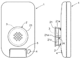
本実施形態に係る壁掛け式の火災警報器1は、図2に示すように、正面に、煙を検知する煙検知部2と、音声やブザー等の警報音を発する警報スピーカ3と、LED等による光を点灯または点滅する警報ランプ4とを備える。火災警報器1は、煙検知部2が煙を検知した時に、例えば、煙の濃度が予め設定した閾値より高いか低いかを判断し、煙の濃度が閾値を超えている場合に火災と判定して、警報スピーカ3から警報音を発し、警報ランプ4を点灯させる。火災警報器1には、警報停止ボタン5が設けてあり、これを操作することにより警報スピーカ3からの警報音を停止し、警報ランプ4を消灯することができるようになっている。また、火災警報器1の背面には、火災警報器1を壁材等に固定する取り付け部(図示しない)や、火災警報器1を駆動させる電池を収納する電池収納部(図示しない)等が設けてある。
As shown in FIG. 2, the wall-mounted
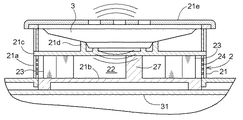
前記煙検知部2は、図1〜図3に示すように、ハウジング21を備えている。ハウジング21は、基板31に取り付けられており、底面部21b、仕切り部21c、蓋部21e、底面部21bと仕切り部21c、及び、仕切り部21cと蓋部21eとの間に設けられた棒状部材21a等を備えている。仕切り部21cの上方には、警報スピーカ3を収容するスピーカ収容空間が形成されている。仕切り部21cには、警報スピーカ3に係合する係合部21dが形成されている。これにより、警報スピーカ3がハウジング21に一体的に取り付けられている。底面部21bと仕切り部21cとの間には、内部に煙を検知する煙検知室22が形成されている。
As shown in FIGS. 1 to 3, the
前記ハウジング21には、複数の鉤状の壁部23が煙検知室22の高さ方向の全長に亘って、煙検知室22の周りを取り囲むように設けてある。これにより、煙検知室22に外部から光を遮断しつつ外部からの煙が流入できるようになっている。それぞれの壁部23はその端部を同一周方向に向けて設けてあり、壁部23のうち火災警報器1を壁に取り付けた状態とした時に最下部となる位置に設けた壁部23aには、他の壁部23と同じ高さの壁で形成され、上方に向けて開口するポケット部23bが設けてある。壁部23の外側には、金網等で構成される防虫網24が設けてあり、煙検知室22に虫等が入らないようにしてある。
A plurality of bowl-
本実施形態のような壁掛け式の火災警報器1では、煙検知室22に侵入した埃(異物の一例)は下方に堆積する。このため、このようなポケット部23bを設けることにより煙検知室22に侵入した埃を効率よく捕捉することができる。また、ポケット部23bを形成する壁部23aの煙検知室22の側の端部は他の煙検知室22の側の壁部23の端部と同一周方向を向くように設けてあり、図1における壁部23aの左側の壁部23との間から流入する空気等はポケット部23bとは反対の方向に流れ、図1における壁部23aの右側の壁部23との間から流入する空気等はポケット部23bの上方を通って流れるように構成してある。このため、外部から流入する空気等がポケット部23bの内部に流入することがなく、一旦ポケット部23bに捕捉した埃を舞い上がらせることはない。尚、ポケット部23bの開口幅は、煙の煙検知室22への流入を妨げない範囲内で大きく形成することが好ましく、これにより埃を捕捉し易くなる。
In the wall-mounted
前記ハウジング21の内部には、煙検知室22に近赤外線等の光を照射する発光部としての発光ダイオード等の発光素子25と、煙検知室22の光を受光する受光部としてのフォトダイオード等の受光素子26とが、それぞれの光軸が煙検知室22の内部で交差するように設けてある。また、発光素子25と受光素子26との間には遮光部としての遮光壁27が設けてあり、発光素子25から受光素子26へ向かう直接光を遮断できるようになっている。このため、受光素子26は、通常時には発光素子25が発する光を受光することはなく、煙検知室22に煙が流入した時にのみ煙による発光素子25が発する光の散乱光を受光できるようになる。煙検知部2は、この散乱光を検出することで煙の存在を検知できるようになっている。
Inside the
前記受光素子26は、遮光壁27及びポケット部23bに対し上方に位置するように配置してある。本実施形態のような壁掛け式の火災警報器1では埃は上方からハウジング21の内部に侵入し易い。このため、受光素子26とポケット部23bとをこのように設けることにより、埃が煙検知室22の内部に侵入し難くなる。又、遮光壁27の下方にポケット部23bを設けてあるので、遮光壁27から落下した埃を捕捉し易い。
The
前記警報スピーカ3は、火災のときには、警報音を発するものであるが、ハウジング21を振動させるのにも用いられる。つまり、可聴域よりも低いあるいは高い周波数の音を発することにより、埃が煙検知室22内に侵入し、埃が遮光壁27内に付着したとしても、警報スピーカ3による振動によって埃が遮光壁27内から脱着して落下し、上方に向けて開口するポケット部23bが埃を捕捉するので、埃による光の乱反射を防止して誤検知を防止できる。従って、警報スピーカ3はハウジング21を振動させる振動発生手段を兼用している。尚、その他の煙検知部2を備えた火災警報器1の構成、機能については、従来公知の火災警報器と同様である。
The
次に、本発明に係る光電式煙感知器の制御構成について説明する。
警報スピーカ3の振動発生手段としての作動を制御するマイコン等の制御手段(図示しない)が備えられており、制御手段が、警報スピーカ3を一定期間作動させてハウジング21を振動させたのち所定の期間が経過すると、条件が満たされたと判別して、警報スピーカ3を作動させるように構成されている。
Next, the control configuration of the photoelectric smoke detector according to the present invention will be described.
A control means (not shown) such as a microcomputer for controlling the operation of the
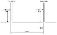
具体的には、図4に示すように、10秒毎に発光素子25が光をパルス照射して、受光素子26が発光素子25から発する光を受光する。そして、発光素子25が光をパルス照射する1秒前に警報スピーカ3を一定期間作動させてハウジング21を振動させる。警報スピーカ3を作動させるタイミングや作動時間は、適宜設定及び設定変更が可能である。例えば、図4のように、1回のパルス照射に対して1回作動させたり、複数回のパルス照射に対して1回作動させる等、埃の堆積度合いに応じて設定・変更可能である。又、警報スピーカ3を定期的(時、日、週、月、年)に作動させてもよい。警報スピーカ3を定期的に作動させる間隔は、適宜設定及び設定変更が可能である。さらに、温度センサ(図示しない)を設けて、温度センサの温度が所定温度になったときに警報スピーカ3を作動させてハウジング21を振動させてもよい。これにより、所定温度を適切に設定することにより、夜と昼の間、あるいは、冬と夏との間で警報スピーカ3を作動させてハウジング21を振動させることができる。
Specifically, as shown in FIG. 4, the
〔第2実施の形態〕
この実施形態では、第1実施形態の構成と異なる制御構成について説明する。
前記制御手段が、受光素子26にて受光された散乱光の光量が所定値以上であると、条件が満たされたと判別して、警報スピーカ3を一定期間作動させるように構成されている。
[Second Embodiment]
In this embodiment, a control configuration different from the configuration of the first embodiment will be described.
The control means is configured to operate the
具体的には、10秒毎に発光素子25が光をパルス照射して、受光素子26が発光素子25から発する光を受光する。そして、受光素子26にて受光された散乱光の光量が警報音を発する閾値以上であると、警報スピーカ3を一定期間作動させてハウジング21を振動させる。次に、発光素子25が光をパルス照射して、受光素子26にて受光された散乱光の光量が依然として該閾値以上である場合には、煙によって散乱される可能性が高いと考えられるので、警報スピーカ3から警報音を発し、警報ランプ4を点灯させる。受光素子26にて受光された散乱光の光量が該閾値より下がった場合には、埃による可能性が高いと考えられるので、警報スピーカ3から警報音を発せず、警報ランプ4を点灯させない。これにより、埃による乱反射と煙による散乱とを区別して誤検知を防止できる。
Specifically, the
さらに、警報音を発する閾値よりも小さい閾値を設定し、受光素子26にて受光された散乱光の光量が該閾値以上である場合に、警報スピーカ3を一定期間作動させてハウジング21を振動させてもよい。つまり、受光素子26にて受光された散乱光の光量が該閾値以上となった場合に、警報スピーカ3を一定期間作動させてハウジング21を振動させる。次に、発光素子25が光をパルス照射して、受光素子26にて受光された散乱光の光量が依然として該閾値以上であると、再び警報スピーカ3を一定期間作動させてハウジング21を振動させ、該閾値を下回るまでハウジング21の振動を繰り返す。
Furthermore, when a threshold value smaller than the threshold value for generating an alarm sound is set and the amount of scattered light received by the
〔別実施形態〕
上記の実施形態においては、ポケット部23bを1つ設けた例を説明したが、複数設けてもよい。この場合、最下部の位置に加え、壁部23の形状等によって生じる気流から埃がより堆積し易い任意の位置に設けることができる。
[Another embodiment]
In the above embodiment, an example in which one
上記の実施形態においては、ポケット部23bを壁部23と同一の素材で形成した例を説明したがこれに限定されない。例えば、ポケット部23bを粘着性部材や帯電性部材等の埃を吸着し易い部材で構成することもできる。これによって、埃をより捕捉し易くなる。
In the above embodiment, the example in which the
上記の実施形態においては、ポケット部23bが壁部23のうち火災警報器1を壁に取り付けた状態とした時に最下部となる位置に設ける構成を例示したが、これに限られるものではなく、ポケット部23bが壁部23のうち火災警報器1を壁に取り付けた状態とした時に下側となる位置に設けてもよい。
In the above embodiment, the configuration in which the
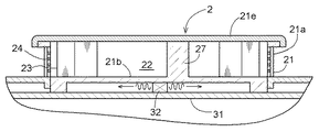
上記の実施形態においては、振動発生手段としての警報スピーカ3がハウジング21を振動させる構成を例示したが、振動発生手段として警報スピーカ3とは別にバイブレータ32を設けてもよい。具体的には、図5のように基板31の上面でハウジング21の側脇にバイブレータ32を設けてハウジング21を振動させたり、図6のように基板31と底面部21bとの間にバイブレータ32を設けてハウジング21を振動させることが考えられる。
In the above embodiment, the configuration in which the
上記の実施形態においては、受光素子26をポケット部23bの上方に設ける構成を例示したが、発光素子25をポケット部23bの上方に設けてもよい。また、発光素子25及び受光素子26をポケット部23bの上方に設けなくてもよい。
In the above embodiment, the configuration in which the
上記の実施形態においては、ハウジング21とは別に金網等で構成される防虫網24を設ける構成を例示したが、ハウジング21と防虫網とを一体成形してもよい。
In the above-described embodiment, the configuration in which the
本発明に係る光電式煙感知器は、煙を検知する煙センサ、煙を検知して警報を発する警報器、煙の濃度を測定する測定器等に適用することができる。 The photoelectric smoke detector according to the present invention can be applied to a smoke sensor that detects smoke, an alarm device that detects smoke and issues an alarm, a measuring device that measures smoke concentration, and the like.
1 火災警報器
2 煙検知部
3 振動発生手段
21 ハウジング
23 壁部
23a 壁部
23b ポケット部
25 発光素子(発光部)
26 受光素子(受光部)
DESCRIPTION OF
26 Light receiving element (light receiving part)
Claims (6)
当該ハウジングの内部に光を照射する発光部と、
前記ハウジングの内部に流入した煙による前記光の散乱光を受光する受光部と、
前記ハウジングを壁に取り付けた状態において、前記複数の壁部のうち少なくとも下側に位置する壁部に上方に向けて開口するように設けられ、前記ハウジングの内部に侵入した異物を捕捉するポケット部と、
前記ハウジングを振動させる振動発生手段と、を備えた光電式煙感知器。 A housing having a plurality of walls that allow smoke from outside to flow in and block direct light from outside;
A light emitting unit for irradiating light inside the housing;
A light receiving unit that receives the scattered light of the light caused by smoke flowing into the housing;
In a state where the housing is attached to the wall, the pocket portion is provided so as to open upward in at least a wall portion located on the lower side of the plurality of wall portions, and captures foreign matter that has entered the inside of the housing. When,
A photoelectric smoke detector comprising: vibration generating means for vibrating the housing.
当該制御手段は、予め設定された条件が満たされたときに、前記振動発生手段を一定期間作動させるように構成してある請求項1又は2に記載の光電式煙感知器。 A control means for controlling the operation of the vibration generating means;
The photoelectric smoke detector according to claim 1 or 2, wherein the control means is configured to operate the vibration generating means for a predetermined period when a preset condition is satisfied.
Priority Applications (1)
| Application Number | Priority Date | Filing Date | Title |
|---|---|---|---|
| JP2008238358A JP5438294B2 (en) | 2008-09-17 | 2008-09-17 | Photoelectric smoke detector |
Applications Claiming Priority (1)
| Application Number | Priority Date | Filing Date | Title |
|---|---|---|---|
| JP2008238358A JP5438294B2 (en) | 2008-09-17 | 2008-09-17 | Photoelectric smoke detector |
Publications (2)
| Publication Number | Publication Date |
|---|---|
| JP2010072851A true JP2010072851A (en) | 2010-04-02 |
| JP5438294B2 JP5438294B2 (en) | 2014-03-12 |
Family
ID=42204581
Family Applications (1)
| Application Number | Title | Priority Date | Filing Date |
|---|---|---|---|
| JP2008238358A Expired - Fee Related JP5438294B2 (en) | 2008-09-17 | 2008-09-17 | Photoelectric smoke detector |
Country Status (1)
| Country | Link |
|---|---|
| JP (1) | JP5438294B2 (en) |
Cited By (2)
| Publication number | Priority date | Publication date | Assignee | Title |
|---|---|---|---|---|
| JP2016128989A (en) * | 2015-01-09 | 2016-07-14 | パナソニックIpマネジメント株式会社 | Fire sensor |
| KR20180113737A (en) * | 2017-04-07 | 2018-10-17 | 주식회사 엑스엘 | Ultra thin micro particulate matter sensor |
Citations (7)
| Publication number | Priority date | Publication date | Assignee | Title |
|---|---|---|---|---|
| JP2000235000A (en) * | 1999-02-15 | 2000-08-29 | Matsushita Electric Works Ltd | Light-scattering-type particle detection sensor |
| JP2008027321A (en) * | 2006-07-25 | 2008-02-07 | Tempearl Ind Co Ltd | Fire alarm for dwelling |
| JP2008077473A (en) * | 2006-09-22 | 2008-04-03 | Hochiki Corp | Smoke sensor |
| JP2008102575A (en) * | 2006-10-17 | 2008-05-01 | Yazaki Corp | Fire alarm |
| JP2008134876A (en) * | 2006-11-29 | 2008-06-12 | Matsushita Electric Works Ltd | Fire sensor |
| JP2009087247A (en) * | 2007-10-02 | 2009-04-23 | Osaka Gas Co Ltd | Alarm system |
| JP2009110433A (en) * | 2007-10-31 | 2009-05-21 | New Cosmos Electric Corp | Photoelectric smoke sensor |
-
2008
- 2008-09-17 JP JP2008238358A patent/JP5438294B2/en not_active Expired - Fee Related
Patent Citations (7)
| Publication number | Priority date | Publication date | Assignee | Title |
|---|---|---|---|---|
| JP2000235000A (en) * | 1999-02-15 | 2000-08-29 | Matsushita Electric Works Ltd | Light-scattering-type particle detection sensor |
| JP2008027321A (en) * | 2006-07-25 | 2008-02-07 | Tempearl Ind Co Ltd | Fire alarm for dwelling |
| JP2008077473A (en) * | 2006-09-22 | 2008-04-03 | Hochiki Corp | Smoke sensor |
| JP2008102575A (en) * | 2006-10-17 | 2008-05-01 | Yazaki Corp | Fire alarm |
| JP2008134876A (en) * | 2006-11-29 | 2008-06-12 | Matsushita Electric Works Ltd | Fire sensor |
| JP2009087247A (en) * | 2007-10-02 | 2009-04-23 | Osaka Gas Co Ltd | Alarm system |
| JP2009110433A (en) * | 2007-10-31 | 2009-05-21 | New Cosmos Electric Corp | Photoelectric smoke sensor |
Cited By (3)
| Publication number | Priority date | Publication date | Assignee | Title |
|---|---|---|---|---|
| JP2016128989A (en) * | 2015-01-09 | 2016-07-14 | パナソニックIpマネジメント株式会社 | Fire sensor |
| KR20180113737A (en) * | 2017-04-07 | 2018-10-17 | 주식회사 엑스엘 | Ultra thin micro particulate matter sensor |
| KR101976058B1 (en) * | 2017-04-07 | 2019-08-28 | 주식회사 엑스엘 | Ultra thin micro particulate matter sensor |
Also Published As
| Publication number | Publication date |
|---|---|
| JP5438294B2 (en) | 2014-03-12 |
Similar Documents
| Publication | Publication Date | Title |
|---|---|---|
| JP4347296B2 (en) | Scattered smoke detector | |
| JP5667670B2 (en) | Smoke detector | |
| WO2013061968A1 (en) | Smoke detector | |
| JP5438294B2 (en) | Photoelectric smoke detector | |
| JP5046552B2 (en) | Photoelectric smoke detector | |
| JP2006136276A (en) | Insect collector | |
| JP5117820B2 (en) | Photoelectric smoke detector | |
| JP5038112B2 (en) | Photoelectric smoke detector | |
| JP2010086378A (en) | Photoelectric smoke detector | |
| JP2010277139A (en) | Smoke detector | |
| JP5097597B2 (en) | Fire alarm | |
| JP2010238095A (en) | Photoelectric smoke sensor | |
| JP5379369B2 (en) | Photoelectric smoke detector | |
| JP5133157B2 (en) | Photoelectric smoke detector | |
| JP2008276448A (en) | Fire alarm | |
| JP2009245260A (en) | Fire alarm | |
| JP2013171364A (en) | Optical fire alarm system | |
| JP2010277140A (en) | Photoelectric type smoke detector | |
| JP5237004B2 (en) | Photoelectric smoke detector | |
| CN210006175U (en) | Smoke alarm | |
| JP2010238109A (en) | Photoelectric smoke sensor | |
| JP4656101B2 (en) | smoke detector | |
| JP6858612B2 (en) | Fire alarm | |
| JP2011210212A (en) | Insect screen for smoke sensor and photoelectric smoke sensor | |
| JP2524653B2 (en) | Smoke detectors |
Legal Events
| Date | Code | Title | Description |
|---|---|---|---|
| A621 | Written request for application examination |
Free format text: JAPANESE INTERMEDIATE CODE: A621 Effective date: 20110301 |
|
| A977 | Report on retrieval |
Free format text: JAPANESE INTERMEDIATE CODE: A971007 Effective date: 20120627 |
|
| A131 | Notification of reasons for refusal |
Free format text: JAPANESE INTERMEDIATE CODE: A131 Effective date: 20120705 |
|
| A131 | Notification of reasons for refusal |
Free format text: JAPANESE INTERMEDIATE CODE: A131 Effective date: 20130328 |
|
| A521 | Request for written amendment filed |
Free format text: JAPANESE INTERMEDIATE CODE: A523 Effective date: 20130527 |
|
| TRDD | Decision of grant or rejection written | ||
| A01 | Written decision to grant a patent or to grant a registration (utility model) |
Free format text: JAPANESE INTERMEDIATE CODE: A01 Effective date: 20131114 |
|
| A61 | First payment of annual fees (during grant procedure) |
Free format text: JAPANESE INTERMEDIATE CODE: A61 Effective date: 20131213 |
|
| R150 | Certificate of patent or registration of utility model |
Ref document number: 5438294 Country of ref document: JP Free format text: JAPANESE INTERMEDIATE CODE: R150 Free format text: JAPANESE INTERMEDIATE CODE: R150 |
|
| R250 | Receipt of annual fees |
Free format text: JAPANESE INTERMEDIATE CODE: R250 |
|
| R250 | Receipt of annual fees |
Free format text: JAPANESE INTERMEDIATE CODE: R250 |
|
| R250 | Receipt of annual fees |
Free format text: JAPANESE INTERMEDIATE CODE: R250 |
|
| R250 | Receipt of annual fees |
Free format text: JAPANESE INTERMEDIATE CODE: R250 |
|
| R250 | Receipt of annual fees |
Free format text: JAPANESE INTERMEDIATE CODE: R250 |
|
| LAPS | Cancellation because of no payment of annual fees |