JP2010072433A - Rapid shooting drive control apparatus - Google Patents
Rapid shooting drive control apparatus Download PDFInfo
- Publication number
- JP2010072433A JP2010072433A JP2008240863A JP2008240863A JP2010072433A JP 2010072433 A JP2010072433 A JP 2010072433A JP 2008240863 A JP2008240863 A JP 2008240863A JP 2008240863 A JP2008240863 A JP 2008240863A JP 2010072433 A JP2010072433 A JP 2010072433A
- Authority
- JP
- Japan
- Prior art keywords
- power supply
- supply voltage
- driving
- continuous shooting
- driven
- Prior art date
- Legal status (The legal status is an assumption and is not a legal conclusion. Google has not performed a legal analysis and makes no representation as to the accuracy of the status listed.)
- Granted
Links
Images


Classifications
-
- H—ELECTRICITY
- H04—ELECTRIC COMMUNICATION TECHNIQUE
- H04N—PICTORIAL COMMUNICATION, e.g. TELEVISION
- H04N23/00—Cameras or camera modules comprising electronic image sensors; Control thereof
- H04N23/60—Control of cameras or camera modules
- H04N23/65—Control of camera operation in relation to power supply
- H04N23/651—Control of camera operation in relation to power supply for reducing power consumption by affecting camera operations, e.g. sleep mode, hibernation mode or power off of selective parts of the camera
Abstract
Description
本発明は、カメラにおける連続撮影時の制御動作に関し、特にバッテリ残量との関連において連続撮影の駆動を制御する連写駆動制御装置に関する。 The present invention relates to a control operation at the time of continuous shooting in a camera, and more particularly to a continuous shooting drive control device that controls driving of continuous shooting in relation to a remaining battery level.
カメラには、多様な機能を実現するために多くの電気的、電子的な装置が搭載されており、これらは通常バッテリを電源として駆動される。機能によっては作動に先だってバッテリ残量の確認を行う必要がある。特に消費電力が大きい装置を駆動する際には、途中で動作が停止しないように、起動直前にバッテリ残量の確認を行うことが有効である。 A camera is equipped with many electrical and electronic devices for realizing various functions, and these are usually driven by a battery as a power source. Depending on the function, it is necessary to check the remaining battery power prior to operation. In particular, when driving a device that consumes a large amount of power, it is effective to check the remaining battery level immediately before startup so that the operation does not stop midway.
一般的にバッテリ残量のチェックでは、要求された機能の作動に先立ってバッテリに所定の負荷を加え、負荷端電圧から残量の適否の判定を行っている。またバッテリ残量の判定をより正確にするため、要求された動作に必要とされる消費電力の大きさに応じて負荷の大きさを変更する構成が提案されている(特許文献1参照)。
しかし、化学電池では、内部インピーダンスが高く、かつ負荷が掛けられていない状態が継続すると出力電圧が回復するため、従来のような方法で電圧を測定して電池残量をチェックすると、実際には化学エネルギーが消耗した状態にあっても、残存エネルギーが十分にあると誤判断してしまうことがある。すなわち、化学電池では、バッテリ内部の化学反応を利用して電荷を生成しているため、化学反応物質が十分にあるときには、負荷の要求に対して電荷を十分に供給できるため出力電圧の低下は実質的に端子、電極などの抵抗のみによるが、化学反応物質が減った状態では、要求される電荷そのもの供給が追いつかず、負荷が加えられた当初は要求される電圧を出力するものの、その後急速に出力電圧が低下する。したがって、従来のバッテリチェックでは、バッテリチェック時に電圧が十分にあると判断されて所定の機能の作動が開始されても、その後急激に出力電圧が低下して作動が途中で停止してしまうことがある。 However, in a chemical battery, the output voltage recovers when the internal impedance is high and the load is not applied, so when actually measuring the voltage and checking the remaining battery level using the conventional method, Even when chemical energy is exhausted, it may be misjudged that there is sufficient residual energy. That is, in the chemical battery, since the electric charge is generated by utilizing the chemical reaction inside the battery, when the chemical reaction substance is sufficient, the electric charge can be sufficiently supplied in response to the load demand, so the output voltage is not lowered. Although it depends only on the resistance of terminals, electrodes, etc., when the amount of chemical reactants is reduced, the required charge itself cannot catch up and the required voltage is output at the beginning when a load is applied, but then rapidly The output voltage drops. Therefore, in the conventional battery check, even if it is determined that the voltage is sufficient at the time of the battery check and the operation of the predetermined function is started, the output voltage is suddenly lowered and the operation stops halfway thereafter. is there.
また、このような誤判断を防止するために、バッテリチェックのための電圧閾値を高く設定すると、本来であれば作動可能であった残存エネルギーが十分にある場合であっても、その作動を禁止してしまうこととなる。更に、連続撮影を行う場合には、撮影動作毎にその作動直前に負荷を掛けるバッテリチェックを行うため、高速連写にとって不利である。 In addition, in order to prevent such misjudgment, if the voltage threshold for battery check is set high, the operation is prohibited even if there is sufficient residual energy that was originally operable. Will end up. Furthermore, when continuous shooting is performed, a battery check is performed immediately before the operation for each shooting operation, which is disadvantageous for high-speed continuous shooting.
本発明は、連写モードにおいて、可能な限り高速な連続撮影を維持する連写駆動制御装置を提供することを目的としている。 An object of the present invention is to provide a continuous shooting drive control device that maintains continuous shooting as fast as possible in the continuous shooting mode.
本発明の連写駆動制御装置は、撮像に使用される装置を相対的に高い高負荷条件で駆動する高負荷駆動手段と、この装置を相対的に低い低負荷条件で駆動する低負荷駆動手段と、電圧をモニタするための負荷を電源に接続し、電源電圧を検知する第1電源電圧検知手段と、この装置の作動中に印加される電圧をモニタして電源電圧を検知する第2電源電圧検知手段とを備え、撮像を連続的に行う連続撮影の開始時であって、1回目の撮影動作の開始前に、第1電源電圧検知手段を動作させ、第1電源電圧検知手段により検出される電源電圧が第1閾値よりも高いときには高負荷駆動手段の駆動を開始するとともに、第1閾値よりも低いときには低負荷駆動手段の駆動を開始し、高負荷駆動手段の駆動中に第2電源電圧検知手段を動作させ、低負荷駆動手段の駆動中には第2電源電圧検知手段を動作させないことを特徴としている。 The continuous shooting drive control apparatus of the present invention includes a high load driving means for driving an apparatus used for imaging under a relatively high high load condition, and a low load driving means for driving the apparatus under a relatively low low load condition. A first power supply voltage detecting means for detecting a power supply voltage by connecting a load for monitoring the voltage to the power supply, and a second power supply for detecting the power supply voltage by monitoring the voltage applied during operation of the apparatus Voltage detection means, and at the start of continuous shooting for continuous imaging, the first power supply voltage detection means is operated and detected by the first power supply voltage detection means before the start of the first shooting operation. When the power supply voltage to be applied is higher than the first threshold, the driving of the high load driving means is started. When the power supply voltage is lower than the first threshold, the driving of the low load driving means is started. Operate power supply voltage detection means, low During operation of the load drive means is characterized by not operating the second power supply voltage detecting means.
第2電源電圧検知手段において検出される電源電圧が第2閾値よりも高いときには、高圧負荷駆動手段による駆動を継続し、第2電源電圧検知手段において検出される電源電圧が第2閾値よりも低いときには、低負荷駆動手段による駆動に切り替えることが好ましい。また電源電圧が第2閾値よりも低いときに、続く撮影動作開始時に前記第1電源電圧検知手段を駆動し、これにより検知される電源電圧が第3閾値よりも高いときには、高負荷駆動手段による駆動を継続することが好ましい。 When the power supply voltage detected by the second power supply voltage detecting means is higher than the second threshold value, the driving by the high-voltage load driving means is continued, and the power supply voltage detected by the second power supply voltage detecting means is lower than the second threshold value. Sometimes, it is preferable to switch to driving by low load driving means. Further, when the power supply voltage is lower than the second threshold value, the first power supply voltage detecting means is driven at the start of the subsequent photographing operation. When the power supply voltage detected thereby is higher than the third threshold value, the high load driving means is used. It is preferable to continue driving.
低負荷駆動手段の駆動終了後であって、続く撮影動作開始時に前記第1電源電圧検知手段を駆動する。一方、連続撮影が低負荷駆動手段で開始され、続く撮影動作開始時に駆動される第1電源電圧検知手段において検知される電源電圧が第3閾値よりも高いときには、高負荷駆動手段による駆動に切り替えることが好ましい。また、連続撮影が低負荷駆動手段で開始され、続く撮影動作開始時に駆動される第1電源電圧検知手段において検知される電源電圧が第3閾値よりも低く、第4閾値よりも高いときは低負荷駆動手段による駆動を継続することが好ましい。電池電圧は負荷電流によって上下するが、化学エネルギーは減少してゆくため、一度第3閾値よりも低い判断を受けた場合には、レリーズスイッチが押し続けられている限り、例え第3閾値よりも高い判断が生じても高負荷駆動を駆動せずに低負荷駆動を駆動し続けることが好ましい。 After the driving of the low load driving means, the first power supply voltage detecting means is driven at the start of the subsequent photographing operation. On the other hand, when the continuous shooting is started by the low load driving means and the power supply voltage detected by the first power supply voltage detecting means driven at the start of the subsequent shooting operation is higher than the third threshold, the driving is switched to the high load driving means. It is preferable. Also, when the continuous power supply is started by the low load driving means and the power supply voltage detected by the first power supply voltage detecting means driven at the start of the subsequent photographing operation is lower than the third threshold and low when it is higher than the fourth threshold. It is preferable to continue driving by the load driving means. The battery voltage increases and decreases depending on the load current, but the chemical energy decreases. Therefore, once a determination is made that is lower than the third threshold, as long as the release switch is kept pressed, the battery voltage will exceed the third threshold. Even if a high determination occurs, it is preferable to continue driving the low load drive without driving the high load drive.
更に、連続撮影の2回目以降の撮影動作において駆動される低負荷駆動手段で駆動される第1電源電圧検知手段において検知される電源電圧が第4閾値よりも高いときには、低負荷駆動手段による駆動を継続し、連続撮影の2回目以降の撮影動作において駆動される低負荷駆動手段で駆動される第1電源電圧検知手段において検知される電源電圧が第4閾値よりも低いときには撮影動作を停止する。 Further, when the power supply voltage detected by the first power supply voltage detecting means driven by the low load driving means driven in the second and subsequent photographing operations of the continuous photographing is higher than the fourth threshold value, driving by the low load driving means. And the photographing operation is stopped when the power supply voltage detected by the first power supply voltage detecting means driven by the low load driving means driven in the second and subsequent photographing operations of the continuous photographing is lower than the fourth threshold value. .
更に、連写駆動制御装置は、連続撮影の2回目以降の撮影動作において駆動される低負荷駆動手段で駆動される第1電源電圧検知手段において検知される電源電圧が第4閾値よりも低いことにより前記撮影動作を終了するときに、電源の残量が不足していることを警告する警告手段を備えることが好ましい。 Further, in the continuous shooting drive control device, the power supply voltage detected by the first power supply voltage detecting means driven by the low load driving means driven in the second and subsequent photographing operations of the continuous photographing is lower than the fourth threshold value. Therefore, it is preferable to provide warning means for warning that the remaining amount of power is insufficient when the photographing operation is finished.
第4閾値は第3閾値以下であり、第1閾値は第2閾値よりも小さく、第3閾値は第1閾値よりも小さい。 The fourth threshold is less than or equal to the third threshold, the first threshold is smaller than the second threshold, and the third threshold is smaller than the first threshold.
装置は、ミラーの駆動用モータであり、第2電源電圧検知手段は、ミラーアップ時の2次ブレーキ終了直後に駆動されることが好ましい。更に、電圧をモニタするための負荷と装置とが並列に接続される。 The apparatus is a mirror driving motor, and the second power supply voltage detecting means is preferably driven immediately after the end of the secondary brake when the mirror is raised. Furthermore, a load for monitoring the voltage and the device are connected in parallel.
以上のように、本発明によれば、連写モードにおいて、可能な限り連続撮影を継続させることが可能な連写制御装置を提供することができる。 As described above, according to the present invention, it is possible to provide a continuous shooting control device capable of continuing continuous shooting as much as possible in the continuous shooting mode.
以下、本発明の実施の形態を、図面を参照して説明する。
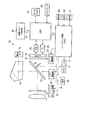
図1は、本発明の一実施形態である連写駆動制御装置が搭載されたカメラの概略的な構成を示すブロック図である。なお、本実施形態では、デジタル一眼レフカメラを例に説明を行うが、連写モードを備えるカメラであれば如何なるカメラであってもよい。
Hereinafter, embodiments of the present invention will be described with reference to the drawings.
FIG. 1 is a block diagram showing a schematic configuration of a camera equipped with a continuous shooting drive control apparatus according to an embodiment of the present invention. In this embodiment, a digital single-lens reflex camera is described as an example, but any camera having a continuous shooting mode may be used.
デジタル一眼レフカメラ10には、撮像レンズ11および絞り12を備えた鏡筒が取り付けられ、光は撮像レンズ11および絞り12を通してカメラ本体内へと導かれる。カメラ本体内には、光軸に対して45°に傾けられたミラー13が配置され、ミラー13で反射された光は、焦点板(図示せず)およびペンタプリズム14に向けて反射され、ファインダ光学系(図示せず)へと導かれるとともに、その一部は測光用の測光IC15へと入射する。また、ミラー13の一部はハーフミラーとされ、ハーフミラー部を透過した光は、ミラー13に取り付けられたサブミラー16で反射されオートフォーカス用のAFモジュール17へと入射する。
The digital single-
ミラー13の後方には、メカニカルシャッタ18が配置され、更にその後方には撮像素子(CCD)19が配置される。ミラー13およびサブミラー16は、ミラー駆動部20に設けられた電動モータにより駆動され、その動作はコントロール回路(CPU)21により制御される。また、メカニカルシャッタ18の駆動は、シャッタ駆動部22に設けられた電動モータにより駆動され、その動作はコントロール回路21により制御される。
A
CCD19は、タイミングコントローラ(TC)23を介してデジタルシグナルプロセッサ(DSP)24に接続され、DSP24は、コントロール回路21からの指令に基づいて、タイミングコントローラ(TC)23を駆動して、CCD19の駆動を制御する。CCD19において検出された画像信号は、アナログフロントエンド(AFE)プロセッサ25を介してデジタル信号に変換されDSP24へと入力され、画像メモリ(DRAM)26に一時的に保存されるとともに、DSP24において、各種所定の画像処理を施されてモニタ(LCD)27に表示される。また、画像データは、必要に応じてメモリカード28などの記録媒体に記録される。
The
コントロール回路21には、メインスイッチ(MAIN)29、測光スイッチ(SWS)30、レリーズスイッチ(SWR)31が接続されており、メインスイッチ29がON状態にされると、電源32から鏡筒およびカメラ本体内の各デバイスに電力が供給される。また、レリーズボタン〈図示せず〉が半押しされると、測光スイッチ(SWS)30がON状態とされ、コントロール回路21では、測光IC15からの信号に基づいて測光処理が行われ絞り12が駆動されるとともに、AFモジュール17からの信号に基づいてオートフォーカス処理が行われ撮像レンズ11が駆動される。
A main switch (MAIN) 29, a photometry switch (SWS) 30, and a release switch (SWR) 31 are connected to the
更にレリーズボタン(図示せず)が全押しされると、ミラー駆動部20が駆動されてミラー13が上方へと跳ね上げられるとともに、シャッタ駆動部22が駆動されてメカニカルシャッタ18が駆動される。このとき、CCD19が駆動され被写体像がCCD19において撮像される。
Further, when a release button (not shown) is fully pressed, the
また、電源32からの電源ライン34には、バッテリチェック回路33がミラー駆動部20と並列に接続されており、コントロール回路21からの指令に基づいて所定のタイミングでバッテリチェックが行われる(第1電源電圧検知手段)。なお、図1において、電源系としては本発明との関連が深いミラー駆動部20、コントロール回路21、電源32、バッテリチェック回路33、電源ライン34の関連のみが模式的に示されるが、電源32は、カメラ本体および鏡筒のあらゆるデバイスに電源ライン34を介して接続され、各デバイスに電力を供給している。
In addition, a
図2は、ミラー駆動部20、コントロール回路(CPU)21、電源32、バッテリチェック回路33、電源ライン34の関係を示す回路図である。電源32には、リチウム電池やアルカリ電池などの化学電池が使用され、電池33のマイナス極はグラウンドされ、プラス極は電源ライン34へと接続される。
FIG. 2 is a circuit diagram showing the relationship among the
ミラー駆動部20には、ミラー13を駆動するための電動モータ35が備えられ、例えばH型ブリッジ回路により正転/逆転駆動される。すなわち、トランジスタQ1、Q4のみを同時にONすると、電流が電源ライン34からトランジスタQ1、モータ35、トランジスタQ4と流れモータ35は正転する。一方、トランジスタQ2、Q3のみを同時にONすると、電流が電源ライン34からトランジスタQ2、モータ35、トランジスタQ3と流れモータ35は逆転する。トランジスタQ1〜Q4のON/OFFは、コントロール回路21のモータドライブ回路36によって制御される。なお、トランジスタQ3とQ4だけを同時にONとするとモータ35にブレーキをかける動作となる。
The
バッテリチェック回路33は、スイッチ37と、これに直列に接続された例えば数Ω程度の負荷抵抗38とからなる。すなわち、バッテリチェック専用の負荷抵抗38の一端はスイッチ37に接続されており、他端はグランドに接続されている。スイッチ37がONされると、バッテリチェック用の負荷抵抗38は、電源ライン34と接続され、電源ライン34から負荷抵抗38を通してグラウンドへと電流が流れる。スイッチ37のON/OFFは、コントロール回路21のスイッチ制御ポート39からの信号に基づいて制御される。
The
図2に示されるように、ミラー駆動部20とバッテリチェック回路33は、電源ライン34に並列に接続される。また、電源ライン34は、コントロール回路21のA/D入力部40に接続される。すなわち、電源ライン34の電圧は、A/D入力部40においてデジタル信号に変換され、コントロール回路21に入力される。
As shown in FIG. 2, the
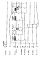
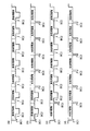
次ぎに図3、図4を参照して、1回の撮影におけるモータ35の2つの駆動方式について説明する。本実施形態において、ミラー13の駆動方式には、2つのモード、すなわち、相対的に消費電力が大きい方式でモータ35を駆動する高負荷駆動モードと、相対的に消費電力の少ない方式でモータ35を駆動する低負荷駆動モードが用意される。図3、図4は、各モードでのミラー13、モータ35、メカニカルシャッタ18の動作タイミングを説明するためのタイミングチャートであり、図3は高負荷駆動モード、図4は低負荷駆動モードのタイミングチャートに対応する。
Next, with reference to FIG. 3 and FIG. 4, two driving methods of the
図3、図4において、(a)はレリーズスイッチ31のON/OFF状態を示し、(b)はミラー13の上下位置を示す。また、(c)はミラー用の電動モータ35の正転/反転/OFF状態を示し、(d)、(e)はミラー13のアップ位置およびダウン位置を検知するミラーアップスイッチ(SWMRUP)とミラーダウンスイッチ(SWMRDN)のON/OFF状態を示す。なお、ミラー駆動機構は、モータ35の一連の正転駆動によりミラーアップ動作およびミラーダウン動作を行うもので、ミラーアップスイッチ(SWMRUP)およびミラーダウンスイッチ(SWMRDN)は、モータ35の回転部に設けられたブラシ機構によりON/OFFされ、その位置を把握するものである。また、(f)、(g)は、メカニカルシャッタ18の先幕、後幕の駆動を制御するシャッタマグネットESMg1、ESMg2のON/OFF状態を示し、(h)は、シャッタマグネットESMg1、ESMg2のON/OFF動作によるメカニカルシャッタ18のシャッタ上下動作を示し、Tvがシャッタ時間に対応する。
3 and 4, (a) shows the ON / OFF state of the
図3、図4に示されるように、高負荷駆動モード、低負荷駆動モードの何れにおいても、モータ35は、ミラーアップ動作およびミラーダウン動作の初期においてPWM制御が行われる。しかし、高負荷駆動モードでは、PWM制御時間が低負荷駆動モードに比べて相対的に短い。例えば、高負荷駆動モードでは、ミラーアップおよびミラーダウン開始時に約10ミリ秒のPWM制御が行われるが、低負荷駆動モードでは、40ミリ秒に渡ってPWM制御が行われる。PWM制御中は電流量をプログラムによって制限しているためモータへの流入電流を制限し消費電力を抑えることができるが、モータへの流入電流の制限時間が少ない程、モータのトルクが増加し回転の加速度が大きくなる。したがって、高負荷駆動モードでは、ミラーアップ、ミラーダウンの動作時間が低負荷駆動モードよりも短く、高速な駆動が可能であるが、消費電力が大きくなる。なお、図3、図4において横軸のタイムスケールは異なる。
As shown in FIGS. 3 and 4, in both the high load drive mode and the low load drive mode, the
すなわち、図3の高負荷駆動モードでは、時点t1においてモータ35が10ミリ秒間に渡ってPWM制御されて正転されるがその後は連続的に電力が供給され、ミラー13はミラーアップ位置に向けて跳ね上げられる。ミラーアップ位置に到達する直前の時点t2において、モータ35への電力供給がOFFされるとともに、一次ブレーキが掛けられる。ミラー13がミラーアップ位置に達した直後、モータ35はバウンド等の影響を考慮し、ミラー13をストッパに押し当てるため再び瞬間的に正転され(t3)、その後直ちに、所定時間、例えば12ミリ秒に渡りPWM制御による逆転ブレーキが掛けられる。またその後、モータ35への電力供給がOFFされ(時点t4)、2次ブレーキが所定時間掛けられる。この2次ブレーキ作動によりミラー13はミラーアップ位置に安定した静止状態となる。2次ブレーキ作動中にメカニカルシャッタ18が露光時間Tvに渡って開かれ、ミラー13はミラーアップ位置に保持される。
That is, in the high load drive mode of FIG. 3, at the time t1, the
露光時間Tvに対応した時点t5に達すると、モータ35は再び例えば10ミリ秒の期間に渡ってPWM制御により正転され、ミラー13はミラーダウン位置に向けて下げられる。ミラー13がミラーダウン位置に達するとモータ35への電力供給がOFFされて、ダウン時の1次ブレーキが掛けられる(t6)。その後、モータ35は例えば10ミリ秒に渡ってPWM制御により正転された後、一定時間連続的に正転方向に電力が供給される。更に所定時間に渡って逆転ブレーキが掛けられた後(t7)、ダウン時の2次ブレーキが所定時間掛けられた後、モータ35はOFFされて(t8)、この高負荷駆動モードにおける一回の撮影動作は終了する。
When the time point t5 corresponding to the exposure time Tv is reached, the
一方、図4の低負荷駆動モードでは、ミラーアップ動作始動時およびミラーダウン動作始動時のPWM制御の長さが、高負荷駆動モードよりも長く設定され(例えば4倍の40ミリ秒)、またダウン時における一次ブレーキ直後の正転も全てPWM制御で行われるが、その他の制御は図3の高速駆動モードと同様である。このような制御により、低負荷駆動モードでは、ミラー13のアップ動作およびダウン動作に高負荷駆動モードよりも時間が掛かるが、消費電力を低減することができる。
On the other hand, in the low load drive mode of FIG. 4, the length of the PWM control at the start of the mirror up operation and the mirror down operation is set to be longer than that of the high load drive mode (for example, four
次ぎに図2、図5、図6を参照して、本実施形態における、連写モードでのモータ35の駆動方法について説明する。なお、本実施形態では、複数のバッテリチェックの方法と、複数の閾値を用意するとともに、異なるタイミングでバッテリチェックを行うことにより、高負荷駆動モードと低負荷駆動モードを使い分け、電池の消耗に合わせて誤動作させることなく、可能な限り高速な連続撮影を継続できるようにする。
Next, a method for driving the
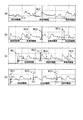
図5は、連写モードでのバッテリチェックのタイミングと、バッテリチェックの結果に基づくモータ35の各モードを用いた作動シークエンスを示す模式的なタイミングチャートである。なお、各タイミングチャートにおいて、横軸は時間、縦軸は電源ライン34の電圧値に対応する。
FIG. 5 is a schematic timing chart showing the battery check timing in the continuous shooting mode and the operation sequence using each mode of the
なお、図5(a)は、電池残量が高負荷駆動モードで連写するのに十分なときの動作パターンの一例を示し、図5(b)は、電池残量が始めは高負荷駆動モードを作動するのに十分であったが、その後高負荷駆動モードでは作動できないレベルまで低下したときの動作パターンを示す。また、図5(c)は、何らかの原因で始め電池残量が高負荷駆動モードには十分でないと判断されたが、実際には高負荷駆動モードでの駆動に十分な電池残量があった場合の動作パターンの一例を示し、図5(d)は、連写モード開始当初から電池残量が高負荷駆動モードで作動するには十分ではなかった場合の動作パターンを示すものである。なお、図5(a)〜図5(b)において、高負荷駆動モードにおける時間スケールと低負荷モードにおける時間スケールは実際には異なる。 FIG. 5A shows an example of an operation pattern when the remaining battery level is sufficient for continuous shooting in the high-load driving mode, and FIG. 5B shows high-load driving when the remaining battery level is initially high. The operating pattern is shown when it is sufficient to operate the mode but then drops to a level where it cannot operate in the high load drive mode. Further, in FIG. 5C, it was determined that the remaining battery level was not sufficient for the high load drive mode for some reason, but actually there was sufficient battery level for driving in the high load drive mode. FIG. 5D shows an operation pattern when the remaining battery level is not sufficient to operate in the high load drive mode from the beginning of the continuous shooting mode. 5A to 5B, the time scale in the high load drive mode and the time scale in the low load mode are actually different.
本実施形態では、バッテリチェックの処理として、電源32にバッテリチェック回路33の負荷を加えて電源ライン34の電圧を検知することにより電池残量を判定する第1電源電圧検知処理と、モータ35による負荷を加えたときの電源ライン34の電圧を検知することにより電池残量を判定する第2電源電圧検知処理を組み合わせてバッテリチェックを行う。
In the present embodiment, as the battery check process, the first power supply voltage detection process for determining the remaining battery level by adding the load of the
まず、連写モードが選択され、レリーズスイッチ31がONされた直後であって、最初の撮影動作が開始される直前には(タイミングBC1)、常に第1電源電圧検知処理が作動される(図5(a)〜(d))。すなわち、モータ35がOFF状態において、スイッチ37がON状態とされ、電源32にはバッテリチェック用の負荷抵抗38による負荷が加えられる。また、このときの電源ライン34の電圧がA/D入力部40を介してデジタル値としてコントロール回路21に入力される。
First, immediately after the continuous shooting mode is selected and the
連写モード作動直後の第1電源電圧検知処理において検出された電圧が所定の第1閾値(例えば4.6V)よりも高いときには、電池残量は高負荷駆動モードによる作動に十分であると判断され、高負荷駆動モードによる連続撮影が開始される(図5(a)、図5(b))。一方、連写モード作動直後の第1電源電圧検知処理において検出された電圧が第1閾値以下所定値以上のときは、電池残量は高負荷駆動モードによる作動には不充分であるが、低負荷駆動モードでの作動は可能であると判断され、低負荷駆動モードによる連続撮影が開始される(図5(c)、図5(d))。 When the voltage detected in the first power supply voltage detection process immediately after the continuous shooting mode is activated is higher than a predetermined first threshold (for example, 4.6 V), it is determined that the remaining battery level is sufficient for the operation in the high load drive mode. Then, continuous shooting in the high load drive mode is started (FIGS. 5A and 5B). On the other hand, when the voltage detected in the first power supply voltage detection process immediately after the continuous shooting mode is activated is equal to or less than the first threshold and a predetermined value or more, the remaining battery level is insufficient for the operation in the high load drive mode, It is determined that the operation in the load driving mode is possible, and continuous imaging in the low load driving mode is started (FIGS. 5C and 5D).
なお、連写モード開始時、タイミングBC1において実行される第1電源電圧検知処理は、1回目の撮影を高負荷駆動とするか低負荷駆動とするかの判定にのみ用いられる。 Note that the first power supply voltage detection process executed at the timing BC1 at the start of the continuous shooting mode is used only to determine whether the first shooting is to be performed with high load or low load.
高負荷駆動モードによる撮影が開始された場合には、高負荷駆動モードでの撮影中に、第2電源電圧検知処理として電源ライン34の電圧がA/D入力部40を介してデジタル値としてコントロール回路21に入力される。第2電源電圧検知処理は、各高負荷駆動モードにおいて未だ高負荷が掛けられていない所定のタイミングBC2において実行され、このとき第1電源電圧検知処理は実行されない。すなわち、スイッチ37はOFF状態に維持される。第2電源電圧検知処理を実行するタイミングBC2は、撮影シーケンス中において、比較的電圧が安定するタイミング、例えばミラーアップ期間中であって、例えば図3において、ミラーアップ時の2次ブレーキ作動直後のミラー13の位置が安定した静止状態となるタイミングで行われる。
When shooting in the high load drive mode is started, the voltage of the
なお、第2電源電圧検知処理において、電圧が所定の第2閾値(例えば5.0V)よりも高いときには、電池残量は、高負荷駆動モードによる駆動に十分であると判断され、続く撮影においても、高負荷駆動モードによる撮影動作が継続される。 In the second power supply voltage detection process, when the voltage is higher than a predetermined second threshold (for example, 5.0 V), it is determined that the remaining battery level is sufficient for driving in the high load driving mode, and in subsequent shooting. However, the photographing operation in the high load drive mode is continued.
図5(a)は、高負荷駆動モードにより連写が開始され、その後の全ての高負荷駆動において第2電源電圧検知処理で検知される電圧が第2閾値よりも高い場合を示している。この場合、高負荷駆動モードによる撮影は、第2電源電圧検知処理における電圧が第2閾値以下になって低負荷駆動モードに切り替えられるか、レリーズスイッチ31がOFFされるまで継続される。
FIG. 5A shows a case where continuous shooting is started in the high load drive mode, and the voltage detected by the second power supply voltage detection process in all subsequent high load drives is higher than the second threshold value. In this case, the imaging in the high load drive mode is continued until the voltage in the second power supply voltage detection process is equal to or lower than the second threshold and the mode is switched to the low load drive mode or the
一方、図5(b)は、1回目の高負荷駆動モードでの撮影では、第2電源電圧検知処理において電圧が第2閾値よりも高く、電池残量が高負荷駆動モードの作動に十分であると判断されたが、2回目の高負荷駆動モードでの撮影における第2電源電圧検知処理において、電圧が第2閾値以下となった場合に対応する。第2閾値以下の電圧である場合には、電池残量が高負荷駆動モードの撮影に十分でない可能性があるので、バッテリチェック回路33を用いた第1電源電圧検知処理を次の撮影動作開始時に実行する(図5(b)のタイミングBC3)。
On the other hand, in FIG. 5B, in the first shooting in the high load drive mode, the voltage is higher than the second threshold in the second power supply voltage detection process, and the remaining battery level is sufficient for the operation in the high load drive mode. Although determined to be present, this corresponds to the case where the voltage is equal to or lower than the second threshold value in the second power supply voltage detection process in the second shooting in the high load drive mode. If the voltage is equal to or lower than the second threshold, the remaining battery level may not be sufficient for shooting in the high-load drive mode, so the first power supply voltage detection process using the
この第1電源電圧検知処理は、撮影動作開始直後に実行され、モータ35への電力供給を行いながら実行される。すなわち、図5のBC3のタイミング(撮影動作開始時)においてバッテリチェック回路33のスイッチ37がONされ、負荷抵抗38にも電源ライン34からの電圧が印加される。このときの電圧が第3閾値(例えば4.3V)よりも高ければ、電池残量は高負荷駆動モードの作動に十分であると判断され、続く撮影は高負荷駆動モードで実行される。
This first power supply voltage detection process is executed immediately after the start of the photographing operation, and is executed while supplying power to the
一方、検知された電圧が第3閾値以下の場合には、電池残量が高負荷駆動モードの作動に十分でないと判断され、それ以降の撮影では低負荷駆動モードでの撮影が行われる。なお、高負荷駆動モードから低負荷駆動モードへと一旦切り替えられた後の各低負荷駆動モードでは、撮影動作開始時に第1電源電圧検知処理が実行され、検出された電圧は所定の第4閾値(例えば4.0V)と比較される。電池電圧は負荷電流によって上下するが、化学エネルギーは減少してゆくため、一度第3閾値(4.3V)よりも低い判断を受けた場合は、レリーズスイッチが押し続けられている限り、たとえ第3閾値(4.3V)よりも高い判断が生じても高負荷駆動を駆動せず、低負荷駆動を駆動し続けることが好ましい。また、第2電源電圧検知処理も実行されない。 On the other hand, when the detected voltage is equal to or lower than the third threshold value, it is determined that the remaining battery level is not sufficient for the operation in the high load driving mode, and in the subsequent shooting, shooting in the low load driving mode is performed. Note that in each low load drive mode once switched from the high load drive mode to the low load drive mode, the first power supply voltage detection process is executed at the start of the photographing operation, and the detected voltage is a predetermined fourth threshold value. (For example, 4.0V). The battery voltage varies depending on the load current, but the chemical energy decreases. Therefore, once the judgment is made lower than the third threshold value (4.3 V), as long as the release switch is kept depressed, Even if a determination higher than 3 threshold (4.3 V) occurs, it is preferable not to drive the high load drive and continue to drive the low load drive. Further, the second power supply voltage detection process is not executed.
電圧が第4閾値より高ければ、低負荷駆動モードによる連写が、レリーズスイッチ31がOFFされるまで継続される。また、電圧が第4閾値以下になると、連続撮影は停止され、電池残量が少ないことを例えばモニタなどにシンボルとして視覚的に表示するか、あるいは警告音などで聴覚的にユーザに報知する。
If the voltage is higher than the fourth threshold value, continuous shooting in the low load drive mode is continued until the
なお、図5(b)は、高負荷駆動モードで連写が開始し、2回目の高負荷モード撮影における第2電源電圧検知処理で電圧が第2閾値よりも低いと判定され、更に3回目の撮影動作開始時の第1電源電圧検知処理における検知電圧が第3閾値よりも低く、その後の各低負荷駆動モードにおける第1電源電圧検知処理での電圧が第4閾値よりも高い場合を表している。 In FIG. 5B, continuous shooting starts in the high load drive mode, and it is determined that the voltage is lower than the second threshold in the second power supply voltage detection process in the second high load mode shooting, and the third time. Represents a case where the detection voltage in the first power supply voltage detection process at the start of the photographing operation is lower than the third threshold value, and the voltage in the first power supply voltage detection process in each subsequent low load drive mode is higher than the fourth threshold value. ing.
図5(c)、図5(d)のタイミングチャートは何れも、連写モード開始時のBC1のタイミングで実行された第1電源電圧検知処理で検知された電圧が第1閾値よりも低くかった場合を例示する。BC1のバッテリチェックにおいて、電圧が第1閾値よりも低かった場合には、電池残量が高負荷駆動モードでの撮影には十分ではない可能性があると判断して、低負荷駆動モードの撮影により連写が開始される。低負荷駆動モードで撮影が開始された場合には、次の撮影動作開始時に、BC3のタイミングで第1電源電圧検知処理が実行される。 In both the timing charts of FIGS. 5C and 5D, the voltage detected in the first power supply voltage detection process executed at the timing BC1 at the start of the continuous shooting mode is lower than the first threshold value. An example is given. In the battery check of BC1, if the voltage is lower than the first threshold value, it is determined that the remaining battery level may not be sufficient for shooting in the high load drive mode, and shooting in the low load drive mode is performed. To start continuous shooting. When shooting is started in the low load drive mode, the first power supply voltage detection process is executed at the timing BC3 when the next shooting operation starts.
図5(c)は、最初の低負荷駆動モードでの撮影終了直後の第1電源電圧検知処理において検知された電圧が、第3閾値よりも高かった場合に対応し、2回目の撮影は高負荷駆動モードに切り替えられる。このときには図5(a)、(b)のときと同様に、タイミングBC2において第2電源電圧検知処理が実行される。なお、その後の第2電源電圧検知処理により検出される電圧が第2閾値よりも高ければ、レリーズスイッチ31がOFFされるまで高負荷駆動モードでの撮影が継続される。また、第2電源電圧検知処理により検出される電圧が第2閾値よりも低いときには、再び低負荷駆動モードに切り替えられ、その後は、図5(b)における3回目の撮影以降の連続撮影と同様に、低負荷駆動モードによる撮影のみが繰り返される。
FIG. 5C corresponds to the case where the voltage detected in the first power supply voltage detection process immediately after the end of shooting in the first low-load drive mode is higher than the third threshold value. Switch to load drive mode. At this time, as in the case of FIGS. 5A and 5B, the second power supply voltage detection process is executed at the timing BC2. If the voltage detected by the subsequent second power supply voltage detection process is higher than the second threshold value, shooting in the high load drive mode is continued until the
図5(d)は、最初の低負荷駆動モードでの撮影終了直後の第1電源電圧検知処理において検知された電圧が、第3閾値よりも低かった場合に対応し、その後の撮影は、図5(b)における3回目の撮影以降の連続撮影と同様に、低負荷駆動モードによる撮影のみが繰り返される。すなわち、各低負荷駆動モードでの第1電源電圧検知処理における電圧が第4閾値よりも低くなるか、レリーズスイッチ31がOFFされるまで、低負荷駆動モードによる連写が継続される。なお、何れの低負荷駆動モードの第1電源電圧検知処理においても、電源ライン34の電圧が第4閾値よりも低くなったときには、連写動作は停止され、電池残量が少ないことを警告する。もし、最初の低負荷駆動モードでの撮影終了直後の第1電源電圧検知処理において検知された電圧が、第4閾値よりも低かった場合はただちに電池残量が少ないことを警告する。
FIG. 5D corresponds to the case where the voltage detected in the first power supply voltage detection process immediately after the end of shooting in the first low-load drive mode is lower than the third threshold value. Similar to the continuous shooting after the third shooting in 5 (b), only the shooting in the low load drive mode is repeated. That is, continuous shooting in the low load drive mode is continued until the voltage in the first power supply voltage detection process in each low load drive mode becomes lower than the fourth threshold value or the
なお、図6(a)〜(d)のグラフに、図5(a)〜(d)の各々における具体的な消費電流の時系列変化を部分的に示し、各タイミングBC1、BC2、BC3をこのグラフ上において示す。なお図6において縦軸は電流値であり、横軸は時間であるが、図6(a)〜(d)の間において時間スケール同一ではない。 6A to 6D partially show specific time-series changes in current consumption in each of FIGS. 5A to 5D, and the timings BC1, BC2, and BC3 are shown. This is shown on this graph. In FIG. 6, the vertical axis represents the current value and the horizontal axis represents time, but the time scale is not the same between FIGS.
次ぎに図7のフローチャートを参照して、本実施形態の連写モードにおける連続撮影動作について説明する。 Next, the continuous shooting operation in the continuous shooting mode of the present embodiment will be described with reference to the flowchart of FIG.
連写モードが選択されるとステップS100が実行される。ステップS100では、レリーズスイッチ(SWR)31がOFF状態であるか否かが判定される。レリーズスイッチ(SWR)31がOFF状態であれば、この判定が繰り返され、ON状態であれば、ステップS102において、電池残量の状態を示すフラグBatEmptyが立っているか否か判定される。フラグBatEmptyが立っていれば、電池残量が少ないことを報知するとともに、処理はステップS100に戻り、あらためてレリーズスイッチSWRがON状態とされるまでステップS100の判定が繰り返される。 When the continuous shooting mode is selected, step S100 is executed. In step S100, it is determined whether or not the release switch (SWR) 31 is in an OFF state. If the release switch (SWR) 31 is in the OFF state, this determination is repeated. If the release switch (SWR) 31 is in the ON state, it is determined in step S102 whether or not the flag BatEmpty indicating the remaining battery level is set. If the flag BatEmpty is set, it is notified that the remaining battery level is low, and the process returns to step S100, and the determination in step S100 is repeated until the release switch SWR is turned on again.
ステップS102において、フラグBatEmptyが立っていなければ、ステップS104において、バッテリチェック回路33のスイッチ37がONされ、負荷抵抗38のみによる第1電源電圧検知処理(バッテリチェック)がタイミングBC1で実行され、検出された電圧が第1閾値(4.6V)よりも高いか否かが判定される。
If the flag BatEmpty is not set in step S102, the
ステップS104における電圧が第1閾値以下であれば、ステップS106において、モータ35が低負荷駆動モードで駆動され、第1閾値よりも高ければステップS130において高負荷駆動モードで駆動される。ステップS106において低負荷駆動モードで駆動された後、ステップS108において、ステップS100と同様にレリーズスイッチ(SWR)31がOFF状態であるか否かが判定される。レリーズスイッチ(SWR)31がOFF状態であれば、処理はステップS100に戻り、ON状態であればステップS110において、タイミングBC3において第1電源電圧検知処理が実行され電源ライン34の電圧が検知され、その値が第3閾値(4.3V)よりも高いか否かが判定される。
If the voltage in step S104 is equal to or lower than the first threshold value, the
ステップS110において電圧が第3閾値よりも高ければ処理はステップS136に移り、ステップS136おいてモータ37が高負荷駆動モードで駆動される(後述)。一方、第3閾値以下であればステップS111において、電圧が第4閾値(4.0V)よりも高いか否かが判定される。第4閾値よりも高ければ、ステップS112において、モータ37が低負荷駆動モードで駆動される。一方、第4閾値以下であれば、ステップS160においてフラグBatEmptyが立てられ、警告のための処理が実行される。低負荷駆動モードでモータ37を駆動した場合には、その後ステップS114においてレリーズスイッチSWRのチェックがステップS108と同様に行われ、レリーズスイッチSWRのON状態が継続していれば、ステップS116において、次のBC3のタイミングで第1電源電圧検知処理が実行され、検出された電圧が第4閾値よりも高いか否かが判定される。
If the voltage is higher than the third threshold value in step S110, the process proceeds to step S136, and in step S136, the
ステップS116において、電圧が第4閾値以下であれば、ステップS160においてフラグBatEmptyが立てられ、警告のための処理が実行される。一方、ステップS116において、電圧が第4閾値よりも高いと判定されたときには、ステップS118において低負荷駆動モードによりモータ37が駆動され、以下ステップS114〜S118の処理が繰り返される(ステップS120〜S128のみ図示)。
If the voltage is equal to or lower than the fourth threshold value in step S116, a flag BatEmpty is set in step S160, and a warning process is executed. On the other hand, when it is determined in step S116 that the voltage is higher than the fourth threshold value, the
一方、ステップS104において、タイミングBC1におけるバッテリチェック回路33のみによる第1電源電圧検知処理での電圧が第1閾値よりも高く、ステップS130においてモータ37が高負荷駆動モードで駆動された場合には、ステップS132において、タイミングBC2において第2電源電圧検知処理が実行され、検出された電圧が第2閾値(5.0V)よりも高いか否かが判定される。
On the other hand, when the voltage in the first power supply voltage detection process by only the
ステップS132において電圧が第2閾値以下であると判定された場合には、ステップS108へと処理が移り、ステップS108以下の処理が繰り返される。電圧が第2閾値よりも高いときには、ステップS134において、レリーズスイッチSWRがOFF状態であるか否かが判定される。レリーズスイッチSWRがOFF状態にあれば、処理はステップS100に戻り同様の処理が繰り返され、ON状態にあればステップS136において、モータ37が再び高負荷駆動モードで駆動される。
If it is determined in step S132 that the voltage is equal to or lower than the second threshold value, the process proceeds to step S108, and the processes in step S108 and subsequent steps are repeated. When the voltage is higher than the second threshold value, it is determined in step S134 whether or not the release switch SWR is in an OFF state. If the release switch SWR is in the OFF state, the process returns to step S100 and the same process is repeated. If the release switch SWR is in the ON state, the
ステップS136における高負荷駆動モードでの駆動が終了すると、ステップS132〜ステップ136と同様の処理が以下繰り返される(例えばステップS138〜ステップS152のみ図示)。 When driving in the high load drive mode in step S136 is completed, the same processing as in steps S132 to 136 is repeated (for example, only steps S138 to S152 are shown).
以上のように、本実施形態によれば、連写モードにおける連続撮影を、専用のバッテリチェック回路を用いる第1電源電圧検知処理と、撮影動作に使用される装置(ミラー駆動用電動モータ)を駆動しているときの電源ライン電圧を検知する第2電源電圧検知処理とを組み合わせて利用するとともに、複数の閾値を設け、更に連続撮影を複数の閾値と第1、第2電源電圧検知手段の組み合わせによる判定結果に基づいて、高負荷駆動モードと低負荷駆動モードとの組み合わせにて駆動するにより、連写モードにおいて、可能な限り高速な連続撮影を実行することができる。 As described above, according to the present embodiment, the continuous power shooting in the continuous shooting mode includes the first power supply voltage detection process using the dedicated battery check circuit and the device (mirror drive electric motor) used for the shooting operation. The second power supply voltage detection process for detecting the power supply line voltage during driving is used in combination, and a plurality of threshold values are provided, and further, continuous shooting is performed using the plurality of threshold values and the first and second power supply voltage detection means. Based on the determination result of the combination, driving is performed in a combination of the high-load drive mode and the low-load drive mode, so that continuous shooting as fast as possible can be executed in the continuous shooting mode.
すなわち、連写中の状態に合わせて、高負荷、低負荷駆動を使い分けることにより、可能な限り、連続撮影を継続させるとともに、電池残量が十分にあると考えられるときには、簡易な方法でバッテリチェックを行うことにより、高速な連写を維持している。また、一回低負荷駆動を行った後でも、より低い閾値でのバッテリチェックを行い、その結果に基づいて、2回目以降の撮影を高負荷駆動に切り替え可能としているので、例え、何らかの原因で、連写開始時の電源電圧が下がっていても、実際に電池残量が十分にあれば、高負荷駆動に切り替えられ、高速な連写が可能になる。また、高負荷駆動で連写していても、電池残量が少なくなれば、低速負荷駆動に切り替えて、できるだけ長い時間に渡り連続撮影が継続される。 In other words, by continuously using high load and low load drive according to the state during continuous shooting, continuous shooting is continued as much as possible, and when it is considered that the remaining battery level is sufficient, the battery can be used with a simple method. By performing the check, high-speed continuous shooting is maintained. In addition, even after a low load drive is performed once, a battery check at a lower threshold is performed, and based on the result, the second and subsequent shots can be switched to a high load drive. Even if the power supply voltage at the start of continuous shooting is lowered, if the remaining battery level is actually sufficient, it can be switched to high-load driving and high-speed continuous shooting is possible. Even if continuous shooting is performed under high load driving, if the remaining battery level is low, switching to low speed driving is performed and continuous shooting is continued for as long as possible.
なお、本実施形態では、第3閾値を4.3V、第4閾値を4.0Vとした例を用いて説明を行ったが、第3閾値は第4閾値と等しい値(例えば4.0V)であってもよい。 In the present embodiment, the third threshold value is 4.3V and the fourth threshold value is 4.0V. However, the third threshold value is equal to the fourth threshold value (for example, 4.0V). It may be.
また、本実施形態において連続撮影の高負荷駆動に係わる装置は、高電流駆動されるミラーモータの他、高速掃き出し制御時のCCD駆動装置、絞り駆動装置等があり、低負荷駆動に係わる装置としては、電流制限駆動されるミラーモータの他、通常掃き出し制御時のCCD駆動装置、メモリ駆動装置などが挙げられる。これらの本実施形態を適用することも可能である。 In addition, in this embodiment, devices related to high-load driving for continuous shooting include a mirror motor driven at high current, a CCD driving device at the time of high-speed sweep control, an aperture driving device, etc. In addition to a mirror motor driven by current limiting, a CCD driving device, a memory driving device, etc. during normal sweep-out control can be mentioned. These embodiments can also be applied.
10 デジタル一眼レフカメラ
13 ミラー
18 メカニカルシャッタ
19 撮像素子(CCD)
20 ミラー駆動部
21 コントロール回路(CPU)
32 電源(化学電池)
33 バッテリチェック回路
34 電源ライン
35 ミラー用電動モータ
36 モータドライブ回路
37 スイッチ
38 バッテリチェック用負荷抵抗
39 スイッチ制御ポート
40 A/D入力部
10
20
32 Power supply (chemical battery)
33
Claims (12)
前記装置を相対的に低い低負荷条件で駆動する低負荷駆動手段と、
電圧をモニタするための負荷を電源に接続し、電源電圧を検知する第1電源電圧検知手段と、
前記装置の作動中に印加される電圧をモニタして前記電源電圧を検知する第2電源電圧検知手段とを備え、
前記撮像を連続的に行う連続撮影の開始時であって、1回目の撮影動作の開始前に、前記第1電源電圧検知手段を動作させ、
前記第1電源電圧検知手段により検出される電源電圧が第1閾値よりも高いときには前記高負荷駆動手段の駆動を開始するとともに、前記第1閾値よりも低いときには前記低負荷駆動手段の駆動を開始し、
前記高負荷駆動手段の駆動中に前記第2電源電圧検知手段を動作させ、前記低負荷駆動手段の駆動中には前記第2電源電圧検知手段を動作させないことを特徴とする連写駆動制御装置。 High load driving means for driving a device used for imaging under relatively high high load conditions;
Low load driving means for driving the device at relatively low low load conditions;
A first power supply voltage detecting means for detecting a power supply voltage by connecting a load for monitoring the voltage to the power supply;
A second power supply voltage detecting means for monitoring the voltage applied during operation of the device and detecting the power supply voltage;
At the start of continuous shooting for continuously performing the imaging, before starting the first shooting operation, operating the first power supply voltage detection means,
When the power supply voltage detected by the first power supply voltage detecting means is higher than the first threshold, the high load driving means starts to be driven, and when lower than the first threshold, the low load driving means starts to be driven. And
A continuous shooting drive control device, wherein the second power supply voltage detecting means is operated during driving of the high load driving means, and the second power supply voltage detecting means is not operated during driving of the low load driving means. .
When the power supply voltage detected by the first power supply voltage detecting means driven by the low load driving means driven in the second and subsequent photographing operations of the continuous photographing becomes equal to or lower than the third threshold value, the low load 7. The continuous shooting drive control apparatus according to claim 4, wherein only the driving by the driving means is executed.
Priority Applications (2)
| Application Number | Priority Date | Filing Date | Title |
|---|---|---|---|
| JP2008240863A JP5293037B2 (en) | 2008-09-19 | 2008-09-19 | Continuous shooting drive controller |
| US12/562,388 US8159601B2 (en) | 2008-09-19 | 2009-09-18 | Sequential shooting controller |
Applications Claiming Priority (1)
| Application Number | Priority Date | Filing Date | Title |
|---|---|---|---|
| JP2008240863A JP5293037B2 (en) | 2008-09-19 | 2008-09-19 | Continuous shooting drive controller |
Publications (2)
| Publication Number | Publication Date |
|---|---|
| JP2010072433A true JP2010072433A (en) | 2010-04-02 |
| JP5293037B2 JP5293037B2 (en) | 2013-09-18 |
Family
ID=42037263
Family Applications (1)
| Application Number | Title | Priority Date | Filing Date |
|---|---|---|---|
| JP2008240863A Expired - Fee Related JP5293037B2 (en) | 2008-09-19 | 2008-09-19 | Continuous shooting drive controller |
Country Status (2)
| Country | Link |
|---|---|
| US (1) | US8159601B2 (en) |
| JP (1) | JP5293037B2 (en) |
Cited By (2)
| Publication number | Priority date | Publication date | Assignee | Title |
|---|---|---|---|---|
| JP2013225023A (en) * | 2012-04-20 | 2013-10-31 | Canon Inc | Electronic apparatus |
| US9236810B2 (en) | 2014-02-19 | 2016-01-12 | Ricoh Imaging Company, Ltd. | Voltage conversion circuit, strobe device, photographing device and method of reducing surge voltage |
Families Citing this family (1)
| Publication number | Priority date | Publication date | Assignee | Title |
|---|---|---|---|---|
| JP6065526B2 (en) * | 2012-11-06 | 2017-01-25 | 株式会社Ihi | Non-contact power feeding device |
Citations (3)
| Publication number | Priority date | Publication date | Assignee | Title |
|---|---|---|---|---|
| JPS63266439A (en) * | 1987-04-24 | 1988-11-02 | Canon Inc | Electrically-driven driving circuit for camera |
| JPH09197471A (en) * | 1996-01-16 | 1997-07-31 | Kyocera Corp | Battery check device for camera |
| JP2004037822A (en) * | 2002-07-03 | 2004-02-05 | Fuji Photo Film Co Ltd | Battery remaining quantity warning device |
Family Cites Families (8)
| Publication number | Priority date | Publication date | Assignee | Title |
|---|---|---|---|---|
| JPH03215710A (en) | 1990-01-19 | 1991-09-20 | Sumitomo Electric Ind Ltd | Optical fiber measuring instrument |
| JP3215710B2 (en) | 1991-11-29 | 2001-10-09 | 旭光学工業株式会社 | Battery check device |
| US6134391A (en) * | 1998-06-22 | 2000-10-17 | Asahi Kogaku Kogyo Kabushiki Kaisha | Battery residual-power checking apparatus |
| JP2004150951A (en) * | 2002-10-30 | 2004-05-27 | Sanyo Electric Co Ltd | Battery management circuit and electronic apparatus |
| TWI261825B (en) * | 2002-12-16 | 2006-09-11 | Hitachi Maxell | Data recording method and data recording medium |
| JP4298387B2 (en) * | 2003-06-09 | 2009-07-15 | キヤノン株式会社 | Data recording device |
| JP2005195893A (en) * | 2004-01-07 | 2005-07-21 | Canon Inc | Imaging apparatus, its control method and program |
| JP4827443B2 (en) | 2005-06-24 | 2011-11-30 | Hoya株式会社 | Battery check device |
-
2008
- 2008-09-19 JP JP2008240863A patent/JP5293037B2/en not_active Expired - Fee Related
-
2009
- 2009-09-18 US US12/562,388 patent/US8159601B2/en not_active Expired - Fee Related
Patent Citations (3)
| Publication number | Priority date | Publication date | Assignee | Title |
|---|---|---|---|---|
| JPS63266439A (en) * | 1987-04-24 | 1988-11-02 | Canon Inc | Electrically-driven driving circuit for camera |
| JPH09197471A (en) * | 1996-01-16 | 1997-07-31 | Kyocera Corp | Battery check device for camera |
| JP2004037822A (en) * | 2002-07-03 | 2004-02-05 | Fuji Photo Film Co Ltd | Battery remaining quantity warning device |
Cited By (2)
| Publication number | Priority date | Publication date | Assignee | Title |
|---|---|---|---|---|
| JP2013225023A (en) * | 2012-04-20 | 2013-10-31 | Canon Inc | Electronic apparatus |
| US9236810B2 (en) | 2014-02-19 | 2016-01-12 | Ricoh Imaging Company, Ltd. | Voltage conversion circuit, strobe device, photographing device and method of reducing surge voltage |
Also Published As
| Publication number | Publication date |
|---|---|
| US8159601B2 (en) | 2012-04-17 |
| US20100073553A1 (en) | 2010-03-25 |
| JP5293037B2 (en) | 2013-09-18 |
Similar Documents
| Publication | Publication Date | Title |
|---|---|---|
| US4965619A (en) | Image stabilizing device | |
| US8059156B2 (en) | Imaging apparatus controlling blurring correction during switch between image capture mode and playback mode | |
| JP2008519992A (en) | Camera with power supply voltage detector | |
| US7652715B2 (en) | Photographing apparatus with improved system initialization and movement of optical system | |
| JP2008046179A (en) | Camera | |
| JP5293037B2 (en) | Continuous shooting drive controller | |
| US20070172226A1 (en) | Digital single-lens reflex camera | |
| US20170324902A1 (en) | Interchangeable lens operable in reduced power modes, image capturing apparatus and storage medium storing control program | |
| JP2006311748A (en) | Power supply unit and equipment | |
| US6674965B2 (en) | Electric power control device for camera | |
| JP2007080618A (en) | External power supply device | |
| US6256457B1 (en) | Camera having a vibration compensation device and a strobe emitting device | |
| US10447927B2 (en) | Electronic device for detecting object proximity and controlling a display | |
| JP2004212961A (en) | Camera and camera control method based on usable power source | |
| JP2008256844A (en) | Imaging apparatus and its control method | |
| EP1650960B1 (en) | Camera control device and digital still camera | |
| JP3215710B2 (en) | Battery check device | |
| JP4136528B2 (en) | Imaging device | |
| JP2008035678A (en) | Power supply apparatus and imaging apparatus | |
| JP3969716B2 (en) | Imaging device | |
| JP3550600B2 (en) | Imaging device with shake correction function | |
| JP4253089B2 (en) | Imaging device | |
| JP2005221878A (en) | Photographing device and photographing operation control method | |
| JPH0882838A (en) | Zooming camera | |
| JP2007012360A (en) | Electronic equipment and its program |
Legal Events
| Date | Code | Title | Description |
|---|---|---|---|
| A621 | Written request for application examination |
Free format text: JAPANESE INTERMEDIATE CODE: A621 Effective date: 20110628 |
|
| A711 | Notification of change in applicant |
Free format text: JAPANESE INTERMEDIATE CODE: A712 Effective date: 20111221 |
|
| A977 | Report on retrieval |
Free format text: JAPANESE INTERMEDIATE CODE: A971007 Effective date: 20130207 |
|
| A131 | Notification of reasons for refusal |
Free format text: JAPANESE INTERMEDIATE CODE: A131 Effective date: 20130219 |
|
| A521 | Request for written amendment filed |
Free format text: JAPANESE INTERMEDIATE CODE: A523 Effective date: 20130412 |
|
| TRDD | Decision of grant or rejection written | ||
| A01 | Written decision to grant a patent or to grant a registration (utility model) |
Free format text: JAPANESE INTERMEDIATE CODE: A01 Effective date: 20130514 |
|
| A61 | First payment of annual fees (during grant procedure) |
Free format text: JAPANESE INTERMEDIATE CODE: A61 Effective date: 20130527 |
|
| R150 | Certificate of patent or registration of utility model |
Ref document number: 5293037 Country of ref document: JP Free format text: JAPANESE INTERMEDIATE CODE: R150 Free format text: JAPANESE INTERMEDIATE CODE: R150 |
|
| LAPS | Cancellation because of no payment of annual fees |