JP2010072376A - Image forming apparatus - Google Patents
Image forming apparatus Download PDFInfo
- Publication number
- JP2010072376A JP2010072376A JP2008240229A JP2008240229A JP2010072376A JP 2010072376 A JP2010072376 A JP 2010072376A JP 2008240229 A JP2008240229 A JP 2008240229A JP 2008240229 A JP2008240229 A JP 2008240229A JP 2010072376 A JP2010072376 A JP 2010072376A
- Authority
- JP
- Japan
- Prior art keywords
- recording medium
- unit
- paper
- fixing
- fixing unit
- Prior art date
- Legal status (The legal status is an assumption and is not a legal conclusion. Google has not performed a legal analysis and makes no representation as to the accuracy of the status listed.)
- Granted
Links
Images


Classifications
-
- G—PHYSICS
- G03—PHOTOGRAPHY; CINEMATOGRAPHY; ANALOGOUS TECHNIQUES USING WAVES OTHER THAN OPTICAL WAVES; ELECTROGRAPHY; HOLOGRAPHY
- G03G—ELECTROGRAPHY; ELECTROPHOTOGRAPHY; MAGNETOGRAPHY
- G03G15/00—Apparatus for electrographic processes using a charge pattern
- G03G15/65—Apparatus which relate to the handling of copy material
- G03G15/6588—Apparatus which relate to the handling of copy material characterised by the copy material, e.g. postcards, large copies, multi-layered materials, coloured sheet material
-
- G—PHYSICS
- G03—PHOTOGRAPHY; CINEMATOGRAPHY; ANALOGOUS TECHNIQUES USING WAVES OTHER THAN OPTICAL WAVES; ELECTROGRAPHY; HOLOGRAPHY
- G03G—ELECTROGRAPHY; ELECTROPHOTOGRAPHY; MAGNETOGRAPHY
- G03G15/00—Apparatus for electrographic processes using a charge pattern
- G03G15/20—Apparatus for electrographic processes using a charge pattern for fixing, e.g. by using heat
- G03G15/2003—Apparatus for electrographic processes using a charge pattern for fixing, e.g. by using heat using heat
- G03G15/2014—Apparatus for electrographic processes using a charge pattern for fixing, e.g. by using heat using heat using contact heat
- G03G15/2039—Apparatus for electrographic processes using a charge pattern for fixing, e.g. by using heat using heat using contact heat with means for controlling the fixing temperature
-
- G—PHYSICS
- G03—PHOTOGRAPHY; CINEMATOGRAPHY; ANALOGOUS TECHNIQUES USING WAVES OTHER THAN OPTICAL WAVES; ELECTROGRAPHY; HOLOGRAPHY
- G03G—ELECTROGRAPHY; ELECTROPHOTOGRAPHY; MAGNETOGRAPHY
- G03G15/00—Apparatus for electrographic processes using a charge pattern
- G03G15/50—Machine control of apparatus for electrographic processes using a charge pattern, e.g. regulating differents parts of the machine, multimode copiers, microprocessor control
- G03G15/5062—Machine control of apparatus for electrographic processes using a charge pattern, e.g. regulating differents parts of the machine, multimode copiers, microprocessor control by measuring the characteristics of an image on the copy material
-
- G—PHYSICS
- G03—PHOTOGRAPHY; CINEMATOGRAPHY; ANALOGOUS TECHNIQUES USING WAVES OTHER THAN OPTICAL WAVES; ELECTROGRAPHY; HOLOGRAPHY
- G03G—ELECTROGRAPHY; ELECTROPHOTOGRAPHY; MAGNETOGRAPHY
- G03G2215/00—Apparatus for electrophotographic processes
- G03G2215/00362—Apparatus for electrophotographic processes relating to the copy medium handling
- G03G2215/00535—Stable handling of copy medium
- G03G2215/00717—Detection of physical properties
- G03G2215/00751—Detection of physical properties of sheet type, e.g. OHP
-
- G—PHYSICS
- G03—PHOTOGRAPHY; CINEMATOGRAPHY; ANALOGOUS TECHNIQUES USING WAVES OTHER THAN OPTICAL WAVES; ELECTROGRAPHY; HOLOGRAPHY
- G03G—ELECTROGRAPHY; ELECTROPHOTOGRAPHY; MAGNETOGRAPHY
- G03G2215/00—Apparatus for electrophotographic processes
- G03G2215/00362—Apparatus for electrophotographic processes relating to the copy medium handling
- G03G2215/00919—Special copy medium handling apparatus
- G03G2215/00945—Copy material feeding speed varied over the feed path
Abstract
Description
本発明は、複写機、FAX、レーザービームプリンタ等や、静電気を利用して画像を形成する技術に関する。 The present invention relates to a copying machine, a FAX, a laser beam printer, and the like, and a technology for forming an image using static electricity.
トナーを用いた電子写真などの印刷機器は、トナーを用紙等の記録媒体に定着する場合に熱と圧力によって定着させる場合が一般的である。 2. Description of the Related Art Printing apparatuses such as electrophotography using toner are generally fixed by heat and pressure when fixing toner on a recording medium such as paper.
最も良く用いられる方法として、加熱ロールや加熱ベルトを用いて記録媒体に熱を直接加える方法が良く知られている。 As the most frequently used method, a method of directly applying heat to a recording medium using a heating roll or a heating belt is well known.
このように、熱を加えてトナーを溶かす方式では、トナーばかりでなく記録媒体も含めた全体を加熱するため、記録媒体に変形が生じる。この変形に対しては、種々の補正する機構が提案されている。例えば、特許文献1(特開2000−247526号公報)では、用紙に生じたカールに応じてカール補正装置を設け、パスを2系統にすることが提案されている。 As described above, in the method in which the toner is melted by applying heat, not only the toner but also the entire recording medium is heated, so that the recording medium is deformed. Various correction mechanisms have been proposed for this deformation. For example, Patent Document 1 (Japanese Patent Laid-Open No. 2000-247526) proposes providing a curl correction device in accordance with curl generated on a sheet and using two paths.
また、記録媒体の変形を把握するためのアイデアとしては、特許文献2(特開2006−264921号公報)に提案されているように、定着後のカールを検出する方法なども挙げられる。 Further, as an idea for grasping the deformation of the recording medium, there is a method of detecting a curl after fixing as proposed in Japanese Patent Application Laid-Open No. 2006-264921.
用紙からの提案もされており、例えば、特許文献3(特開平09−090668号公報)には、用紙の組成を変更して、記録媒体の熱による変形を防ぐ方法なども提案されている。 For example, Patent Document 3 (Japanese Patent Application Laid-Open No. 09-090668) proposes a method of changing the composition of the paper to prevent deformation of the recording medium due to heat.
そして、特許文献4(特開2000−356861号公報)には、用紙の水分率をみてプロセス速度を変える方法が提案されている。 Patent Document 4 (Japanese Patent Laid-Open No. 2000-356861) proposes a method of changing the process speed in view of the moisture content of the paper.
しかしながら、特許文献1〜3では、記録媒体上のトナーなど樹脂を熱と圧力とを加えることによって定着させる方法は、定着させたい記録材料だけでなく、記録媒体も加熱し、結果として記録媒体では、変形(カール)が起こり、印刷物の商品的価値を下げる他、搬送機構の信頼性を低下させる原因となっている。
However, in
用紙のカールは、用紙内の水分量の違いによって異なることが知られているが、このカールは、同じ用紙の水分量の影響だけでなく、加熱する温度や、記録媒体の種類、厚みによっても異なる。また、熱定着部と記録媒体の粘着力が大きい場合、記録媒体の剥離が上手くいかず、巻きつきが起こるなどの障害が発生する。障害の発生は、生産性の低下や消耗品の消耗、機構部品などの破損を伴う為、避けなければならない。 It is known that paper curl varies depending on the moisture content in the paper, but this curl depends not only on the effect of moisture content on the same paper but also on the heating temperature, the type of recording medium, and the thickness. Different. In addition, when the adhesive force between the heat fixing unit and the recording medium is large, the recording medium does not peel off well and troubles such as winding occur. Occurrence of failures must be avoided because it results in decreased productivity, consumption of consumables, and damage to mechanical parts.
一方で、特許文献4は、記録媒体の水分率を検知しているが、記録媒体のトナー付着量については考慮されていない。トナーは高温下で溶融し、粘着力を発生させる要因になり、トナー付着量が多いほど、粘着力は大きくなる。記録媒体の水分率のみをみて、プロセス速度を変化させる方法では、不十分である。なぜなら記録媒体に印刷される画像の種類によっても、記録媒体の剥離が左右され、トナー付着量による粘着力によっては巻き付きといった障害が発生する。特に、このことは、定着部での温度が高ければ高いほど顕著に現れてくる。
On the other hand,
そこで、本発明はこれらの課題を解決した画像形成装置を提供することにある。 Therefore, the present invention is to provide an image forming apparatus that solves these problems.
上記課題を解決するため本発明は、制御を行うコントローラと、前記コントローラに複数の記録媒体の情報を登録するデータベースと、トナー像を保持する像担持体と、前記像担持体に露光を行う露光手段と、前記像担持体が保持した前記トナー像を記録媒体に転写する転写部と、前記転写部で前記記録媒体に転写された前記トナー像を熱および圧力を加えて前記記録媒体に固着させる定着手段と、前記定着手段に前記定着手段の温度を検知する温度検知手段と備えた画像形成装置において、前記定着部に定着ニップ角度を可変する駆動手段と、前記定着部の前記記録媒体搬送方向上流側に用紙搬送速度を変更可能な速度可変手段と、前記転写部の前記記録媒体搬送方向上流側に前記記録媒体に流れる電流を測定する電流検知手段とを設け、また、前記露光手段の露光量から前記記録媒体にのる前記トナー像のトナー付着量を算定し、前記コントローラは、ユーザによって印刷される前記記録媒体を選択される際に、前記データベースに予め登録してある複数の種類記録媒体の情報に基づいて前記記録媒体の種類を特定し、前記温度検知手段によって前記定着手段の温度を検知し、前記電流検知手段によって測定した前記記録媒体に流れる電流によって前記記録媒体の水分量を求めた後、前記定着部で前記記録媒体が排出するときの力である反力を算出し、また、前記露光手段の露光量から算定した前記記録媒体にのる前記トナー像のトナー付着量を求めることで前記定着部の熱で前記トナー像が溶融し生じる粘着力を算出し、前記コントローラは、前記反力と前記粘着力とを比較し、前記反力が前記粘着力よりも力が上回ると判断したとき、前記定着ニップ角度を決定し、前記決定した定着ニップ角度になるように前記駆動手段を駆動させ、且つ前記用紙搬送速度を決定し、前記決定した用紙搬送速度になるように前記速度可変手段を駆動させることを特徴としている。 In order to solve the above-described problems, the present invention provides a controller that performs control, a database that registers information on a plurality of recording media in the controller, an image carrier that holds a toner image, and an exposure that exposes the image carrier. Means, a transfer section for transferring the toner image held by the image carrier to a recording medium, and the toner image transferred to the recording medium by the transfer section is fixed to the recording medium by applying heat and pressure. An image forming apparatus comprising: a fixing unit; and a temperature detecting unit that detects a temperature of the fixing unit in the fixing unit. A driving unit that varies a fixing nip angle in the fixing unit; and a recording medium conveyance direction of the fixing unit. A speed variable means capable of changing the paper transport speed on the upstream side, and a current detection means for measuring the current flowing in the recording medium on the upstream side in the recording medium transport direction of the transfer unit, Further, the toner adhesion amount of the toner image on the recording medium is calculated from the exposure amount of the exposure means, and the controller registers in advance in the database when the recording medium to be printed is selected by the user. The type of the recording medium is specified based on the information of the plurality of types of recording media, the temperature of the fixing unit is detected by the temperature detecting unit, and the current flowing through the recording medium is measured by the current detecting unit. After obtaining the moisture content of the recording medium, a reaction force, which is a force when the recording medium is discharged by the fixing unit, is calculated, and the amount applied to the recording medium calculated from the exposure amount of the exposure unit is calculated. By calculating the toner adhesion amount of the toner image, the adhesive force generated by melting the toner image by the heat of the fixing unit is calculated, and the controller compares the reaction force and the adhesive force. When the reaction force is determined to be greater than the adhesive force, the fixing nip angle is determined, the driving means is driven to achieve the determined fixing nip angle, and the paper conveyance speed is determined. The speed varying means is driven so as to achieve the determined paper transport speed.
更に、請求項2記載の発明は、前記定着部に前記記録媒体を剥離する剥離手段と、前記剥離手段を駆動させる剥離手段用駆動手段とを設け、前記コントローラは、前記粘着力が前記反力よりも上回ると判断したとき、前記剥離手段を使用すると決定した後に、前記剥離手段用駆動手段を駆動させ、前記剥離手段によって前記定着部から前記記録媒体を剥離させることを特徴としている。
Furthermore, the invention described in
更に、請求項3記載の発明は、前記定着部の前記記録媒体搬送方向下流側に前記記録媒体の変形を補正する手段と、冷却手段とを設けたことを特徴としている。 Further, the invention described in claim 3 is characterized in that means for correcting deformation of the recording medium and cooling means are provided on the downstream side of the fixing unit in the recording medium conveyance direction.
本発明の画像形成装置によれば、印刷のとき定着部でジャム等の障害を防止でき、信頼性を高めることが可能となる。 According to the image forming apparatus of the present invention, it is possible to prevent a failure such as a jam at the fixing unit during printing, and it is possible to improve reliability.
以下に実施例を説明する。なお、本発明は以下の実施例に限定されない。 Examples will be described below. The present invention is not limited to the following examples.
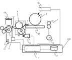
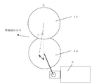
図1は、本発明の画像形成装置の構成概略図である。これについて説明する。用紙1は、図示しない現像装置によって現像されたトナー像を担持する感光体ドラム2からトナー像を転写部で転写された後、図示しない駆動モータによって稼動する用紙搬送用ベルト10によって、定着部4に搬送される。なお、用紙搬送用ベルト10の速度は可変させることができる。定着部4では熱と圧力を加え用紙1に転写されたトナー像を用紙に固着させる。定着部4は、熱源を備える加熱ローラ(以下HRとする)41と、圧力を加えるバックアップローラ(以下BRとする)42とを備え、それぞれアルミニウム材の芯金基材にシリコーンゴムの層がコーティングされている。また、それぞれのゴム硬度を変えてあり、HR41のゴム硬度の方がBR42のゴム硬度よりも硬い構成をとっており、定着ニップ部はわずかに下に凸の形状となる。そのため、用紙1は上側のHR41の方に向かって排出される。この場合、用紙1は下側に凸の形状のくせが付きやすく、定着部4の用紙搬送下流側に位置するデカーラー5のローラによって、定着部4から出た用紙1の温度が低下する前に、このくせを補正する。このデカーラー5のローラは、デカーラー用駆動モータ11を制御することで上下に稼動する。また、このとき用紙1の温度を低下させるために、デカーラー5に設けられた冷却装置13を使用する。これにより、用紙1の温度は低下する。
FIG. 1 is a schematic configuration diagram of an image forming apparatus of the present invention. This will be described. The
転写部の用紙搬送上流側位置に設けられた水分量検知ローラ3は、用紙1に流れる電流を、用紙水分量測定用電流計8で計測を行い、用紙1の水分量を測定する。HR41とBR42とが当接することで形成される定着ニップの角度を変えるためには、アクチュエータ6を駆動させることで行う。これについては、後程詳しく述べる。また、定着部4には、定着部4から用紙1を剥離補助の役割をする剥離爪14も設けられている。剥離爪14は剥離爪用アクチュエータ15の駆動によって動かすことができ、アクチュエータ6の駆動による定着ニップ角度を変える制御によって用紙1を定着部4から剥離できないときに使用する。露光ユニット12はビームによって感光体ドラム2への露光を行う。
The moisture amount detection roller 3 provided at the upstream side of the transfer unit in the sheet conveyance measures the current flowing in the
そして、コントローラ200は、アクチュエータ6、用紙水分量測定用電流計8、デカーラー用駆動モータ11、露光ユニット12および剥離爪用アクチュエータ15を制御するユニットコントローラ7および用紙の情報を登録しておくデータベース9を有している。
The
なお、定着部4での加熱によりトナーが溶融し、これによって粘着力が発生する。そのため、定着部4での用紙1の剥離が上手く行われなくなり、用紙1上のトナー量が多くなる場合は、用紙1が定着部4から排出されずHR41に巻き付き、いわゆるジャムが発生する。この場合、印刷を中断してしまう。そこで、本発明では、用紙のトナーの付着量および用紙の水分量を測定し、用紙搬送速度の制御を行う。
The toner is melted by the heating in the
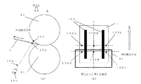
ところで、用紙の水分量とトナー付着量との両方を測定することが望ましい点について、以下に図2を用いて説明する。図2(a)および(b)は、事前に実験を行ったときの実験方法を示したものである。図2(a)は用紙幅方向から定着部4を見た図であり、図2(b)は図2(a)の視点Zから定着部4をみた図である。実験方法としては、レーザ変位計100を用いて、定着部4のHR41の回転の中心に向かい、HR41の表面にレーザ光104を出射して当てる。なお、レーザ光104がHR41に当たる点を測定点101とする。これにより、レーザ変位計100の光源からHR41の表面までの距離を測定する。そして、測定する部分は、図2(b)に示すようにHR41の回転軸方向の測定点101A点、中央の測定点101B点、そして測定点101C点の3点である。
By the way, the point that it is desirable to measure both the moisture content of the paper and the toner adhesion amount will be described below with reference to FIG. FIGS. 2A and 2B show an experimental method when an experiment is performed in advance. 2A is a diagram of the fixing
ここで、用紙1を定着部4に通紙させる。そして、用紙1が定着部4を出るとき、レーザ変位計100から出射されるレーザ光104は、用紙1に当たる。用紙1にレーザ光104が当たる点を用紙の測定点102とよぶ。このとき、レーザ光104が当たる点は、測定点101から用紙の測定点102になり、測定する距離はHR41の表面に当たるときより短くなる。なお、用紙1についても光源からHR41の回転軸方向の測定点102A点、中央の測定点102B点、そして測定点102C点の3点を測定している
さらに、定着部4を通紙する用紙1は、トナーが付着していない白紙とトナーが付着している状態での予め定めた印刷パターンを印刷したものの2パターンを用意した。なお、印刷パターンは、用紙の片面に幅20mmの帯を2本形成させたものである。
Here, the
図3に、定着部4に白紙を通紙したときと印刷パターンを印刷したものを通紙したときのレーザ変位計100の測定結果を示す。定着部4の温度は160℃であり、搬送速度200mm/s、用紙の坪量は135kgとする。図3に示すグラフの縦軸は、HR41からレーザ変位計100の光源からのレーザ光104が用紙1の測定点102に当たるまでの距離で表記している。なお、図3の実験結果はあくまで一例である。なお、図3(a)および(b)のHR41の表面の測定点101Aから用紙上の測定点102Aは、実線、HR41の表面の測定点101Bから102Bは破線、そしてHR41の表面の測定点101Cから102Cは二点鎖線で表している。
FIG. 3 shows the measurement results of the laser displacement meter 100 when a blank sheet is passed through the fixing
先ず、図3(a)は、白紙を通紙した実験結果であり、HR41の表面から用紙の測定点102までの距離は、3.5〜6mmぐらいの範囲をとる。一方で、図3(b)は、印刷パターンを印刷した用紙を通紙した実験結果であり、HR41の表面の測定点101から用紙の測定点102までの距離は、0.9〜6mmぐらいの範囲をとる。両者を比較すると、印刷パターンを印刷した用紙を通紙すると、距離が短くなる。特に、時間が0〜0.1sまでの間で短くなっている(図3(b)の枠で囲った部分)。すなわち、用紙にトナーを付着させた方が、用紙1はHR41側に引き寄せられる傾向が強くなることがわかる。
First, FIG. 3A shows the experimental result of passing a blank sheet, and the distance from the surface of the
なお、この実験では、用紙1の水分量と定着部4での温度を測定し、用紙搬送速度を決定している。しかしながら、定着部4での温度が高ければ高いほど、用紙1が定着部4を出るとき、HR41に引き寄せられる傾向が強くなる。そして、トナーが用紙に付着しているときは、この影響がいっそう強くなり、HR41に用紙1が巻き付くという巻き付きがかなりの頻度で起きてしまう。したがって、用紙の水分量を検知するのみではこの巻き付きを防止することが難しく、用紙1のトナー付着量を同時に測定して巻き付きを防止する必要がある。そこで、本発明は、用紙の水分量とトナー付着量との両方を考慮して、用紙搬送速度を変更する制御を行う。
In this experiment, the moisture content of the
用紙の搬送速度を変更する制御を行う場合、搬送速度を遅くすることが一般的であるが、一方で生産性が下がるという弊害が生じる。これを防止するため、本発明では、用紙搬送速度だけでなく定着部4での定着ニップ角度も変えて、定着部4から用紙1が剥離できるようにする。定着部4での定着ニップ角度は、アクチュエータ6を駆動させて変えられ、アクチュエータ6の駆動ついて図7を用いて説明する。
When performing control to change the sheet conveyance speed, it is common to reduce the conveyance speed, but on the other hand, there is a disadvantage that productivity is lowered. In order to prevent this, in the present invention, not only the sheet conveyance speed but also the fixing nip angle at the fixing
図7は、アクチュエータ6の駆動について示した図である。先ず、定着ニップ角度を決定した後、アクチュエータ6の駆動角度を決定する。そして、アクチュエータ6を駆動させBR42を動かすことで、HR41とBR42とが当接することで形成される定着ニップ角度を可変させることができる。また、アクチュエータ6の駆動角度はHR41の中心とBR42の中心とを結ぶ直線と用紙搬送速度方向とがなす角度(図7ではψである)となっている。なお、HR41を動かすことは熱源となるヒータ等を備えているため駆動制御が難しい。そのため、BR42の方を動かしている。
FIG. 7 is a diagram illustrating driving of the
次に、用紙のトナー付着量および水分量を測定してどのように具体的な制御を行うか、その処理フローについて図4を用いて以下に説明する。なお、これらの制御はコントローラ200が行う。
Next, how the specific amount of control is performed by measuring the toner adhesion amount and moisture amount on the paper will be described below with reference to FIG. These controls are performed by the
先ず、印刷する用紙の種類を特定し、用紙の水分量およびHR41の温度を測定する(S1000)。そして、ユーザが予め使用する複数の種類の用紙情報をデータベース9に登録しておき、ユーザが印刷開始時に印刷する用紙を選択するときに、その選択した用紙がデータベース9内に登録された用紙情報と照合させることで、その印刷する用紙の種類は特定される。HR温度は、定着部4内に設けられた図示しない温度検知器で検知する。一方、転写部の前に設けられた水分量検知ローラ3に流れる電流を、用紙水分量測定用電流計8で計測を行うことで、用紙1の水分量を測定している。なお、用紙の温度に対する変形度合いや、含水率と抵抗の関係等が、事前に判っていれば、より精度の高い制御が可能となる。そのため、それらの情報が特定出来る場合は、予めデータベース9に登録して、その用紙情報を用いて制御を行う。
First, the type of paper to be printed is specified, and the moisture content of the paper and the temperature of the
次に、コントローラ200は、用紙反力を算出する(S1001)。用紙1が定着部4から出るときに用紙自身の剛性によってBR42方向側に引っ張られるような力がはたらき、ここでは用紙反力と呼ぶことにする。この用紙反力は、用紙1を定着部4から剥離され排出するための力である。なお、用紙反力は、印刷する用紙の種類、用紙1の水分量およびHR41の温度からわかり、ユニットコントローラ7がこの力を算出する。
Next, the
その次に、印刷する印刷パターンから用紙1のトナー付着量を算定する(S1002)。用紙1のトナー付着量の算定は、露光ユニット12が感光ドラム2に露光するビームの光量に基づいて行われる。この算定したトナー付着量に基づいて、定着部4での粘着力にどれくらいになるかを算出する(S1003)。この粘着力をトナー付着力とここでは呼ぶことにする。用紙1に付着したトナーは定着部4では溶融して、これにより粘着力を持つようになる。この粘着力が強いと、定着部4の定着ニップ出口でHR41に用紙1が引き寄せられ易くなり、場合によっては用紙巻き付きが発生し、ジャムなどの障害を起こす要因となる。これを回避するためには、用紙反力をトナー付着力よりも上回る必要ある。
Next, the toner adhesion amount of the
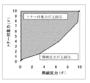
ここで、用紙反力とトナー付着力とでどちらの力がもう一方を上回るかを判定する(S1004)。図5は、用紙反力とトナー付着力とを比較した関係を示した図である。この図5でのグラフを境に斜線部側は、トナー付着力が用紙反力を上回るとき、そしてそれ以外では用紙反力がトナー付着力を上回るときと判定する領域である。なお、本明細書では、トナーの粘着力によって用紙が定着部4を出るときHR41に引き寄せられるときは、「トナー付着力が用紙反力よりも上回る」と表現し、そうでなければ「用紙反力がトナー付着力よりも上回る」と表現する。図5を参照すると、トナー付着力が用紙反力よりも大きさが小さくても、トナー付着力が用紙反力よりも上回ると判定している場合があることがわかる。これについて説明すると、図5に示す用紙反力とトナー付着力とを比較した関係は予め実験によって求めたものであり、実験によるとトナー付着力が用紙反力よりも大きさが小さくても、用紙が定着部4を出るときHR41に引き寄せられる場合があった。すなわち、このような結果は、トナー付着力が用紙反力よりも小さくても、トナー付着力の方が上回っていると判定している。
Here, it is determined which of the sheet reaction force and the toner adhesion force is greater than the other force (S1004). FIG. 5 is a diagram showing the relationship between the paper reaction force and the toner adhesion force. The shaded area on the side of the graph in FIG. 5 is an area where it is determined that the toner adhesion force exceeds the paper reaction force, and otherwise the paper reaction force exceeds the toner adhesion force. In this specification, when the sheet is attracted to the
先ず、上述したように用紙反力およびトナー付着力を求める。その上で、両者の差を算出する。そして、どちらの力が上回るかを決定することができる。このとき、用紙反力がトナー付着力よりも力が上回ると判定したときは、アクチュエータ6の駆動角度を決定し(S1005)、その処理の後に、用紙搬送速度を決定する(S1006)。一方、用紙反力よりもトナー付着力が上回ると判定したときは、アクチュエータ6を駆動させて用紙を定着部4から完全に剥離することができず、このため用紙1がHR41に巻き付いてしまう。そのため、このような場合は、剥離爪14を使用して、用紙1の剥離を補助する(S1007)。剥離爪14は剥離爪用アクチュエータ15の駆動によって動かすことができ、アクチュエータ6の駆動でも用紙1を定着部4から剥離できないときに使用する。なお、剥離爪14を常時使用しない理由として、HR41を傷付けたり、また、剥離爪14自体が劣化してしまう。そのため、トナー付着力が用紙反力よりも力が上回ると判定したときにのみ使用することにする。
First, as described above, the sheet reaction force and the toner adhesion force are obtained. Then, the difference between the two is calculated. And it is possible to determine which force exceeds. At this time, if it is determined that the sheet reaction force exceeds the toner adhesion force, the drive angle of the
ここで、コントローラ200が用紙反力とトナー付着力とを比較し、用紙反力がトナー付着力よりも力が上回ったと判定したとき、どのように定着ニップ角度を決定するのか具体的に説明する。
Here, when the
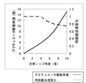
図6は、用紙反力とトナー付着力とを比較し、用紙反力がトナー付着力よりも力が上回ったとき、両者の差を求めて、定着ニップ角度および用紙搬送速度比を決定ためのグラフである。なお、図6のグラフの実線がアクチュエータ6の駆動角度であり、破線が用紙搬送速度比である。そして、用紙反力とトナー付着力との差は、どれくらいの角度で用紙1が定着部4を出ることができるかといった定着ニップ角度に対応している。これについて説明する。用紙反力およびトナー付着力は力の単位で表されるものの、図8に示すように、用紙1が定着部4を出るとき、用紙反力は用紙がBR42方向側にたわむ力によるものであり、一方で、トナー付着力は溶融したトナーの粘着力でHR41方向側に引き付けられることによるものであり、角度に比例したものである。なお、図8で用紙反力はWであり、これはθに比例し、一方でトナー付着力はFであり、これはφに比例する。これらの力の差は角度の差に対応し、この角度差(θ−φ)が定着ニップ角度になる。そして、定着ニップ角度が決定すれば、アクチュエータ6をどれくらいの角度で駆動させればよいのか、また、どれくらいの用紙搬送速度にすればいいのかを決定することができる。
FIG. 6 compares the sheet reaction force and the toner adhesion force, and when the sheet reaction force exceeds the toner adhesion force, the difference between the two is obtained to determine the fixing nip angle and the sheet conveyance speed ratio. It is a graph. Note that the solid line in the graph of FIG. 6 is the driving angle of the
そして、アクチュエータ6の駆動角度は、定着ニップ角度が増加するに略比例して増加させる。しかしながら、用紙搬送速度は、定着ニップ角度が0〜4度程度までは一定だが、定着ニップ角度がそれ以上になると、少し速度を落とす制御を行う。なお、この用紙搬送速度の制御は、実験より求め、定着ニップ角度に対してどれくらいの用紙搬送速度が適切であるかと決めた。但し、速度の低下値は一定でなく比率で定めるようにし、また、定着ニップ角度によって変わってくるものとする。なお、本実施例では、これら用紙反力とトナー付着力との比較、用紙搬送速度変更の決定、アクチュエータの移動角度の決定を行う前に、予め用紙搬送速度を決定しておくものとして、それは、100mm/s〜400mm/sの範囲とする。そして、これらの結果を踏まえ、アクチュエータ6を駆動させたり、用紙搬送速度を変更する。また、用紙搬送速度の変更は、用紙搬送ベルト10の速度を変更することで行われる。
Then, the drive angle of the
ここで、用紙反力やトナー付着力を求め、どのようにアクチュエータ6の駆動角度、用紙搬送速度および剥離爪14の使用を決定するのか、具体例を挙げて説明する。
Here, the sheet reaction force and the toner adhesion force are obtained, and how to determine the driving angle of the
例えば、用紙反力が6で、トナー付着力は3であったとする。すると、用紙反力の方が大きくなり、そして両方の差は3であり、このとき定着ニップ角度は3となる。従って、図6よりアクチュエータ6の駆動角度は、2.5度となる。また、このとき用紙搬送速度は、予め定めた速度にする。
For example, it is assumed that the sheet reaction force is 6 and the toner adhesion force is 3. Then, the sheet reaction force becomes larger, and the difference between the two is 3. At this time, the fixing nip angle is 3. Accordingly, the driving angle of the
別な例を挙げて説明する。例えば、用紙反力が8で、トナー付着力は1であったとする。すると、用紙反力の方が大きくなり、そして両方の差は7であり、このとき定着ニップ角度は2となる。従って、図6よりアクチュエータ6の駆動角度は、11度となる。そして、このとき、用紙搬送速度は、予め定めた速度の0.8倍の速度に変更する。
Another example will be described. For example, it is assumed that the sheet reaction force is 8 and the toner adhesion force is 1. Then, the sheet reaction force becomes larger, and the difference between the two is 7. At this time, the fixing nip angle is 2. Therefore, the driving angle of the
更に、別な例を挙げて説明する。例えば、用紙反力が4で、トナー付着力は2であったとする。この場合、図5を参照すると、用紙反力の方が上回るという判定になる。そして両方の差は2であり、このとき定着ニップ角度は2となる。従って、図6よりアクチュエータ6の駆動角度は1.8度となる。そして、このとき用紙搬送速度は、予め定めた速度にする。
Furthermore, another example is given and demonstrated. For example, it is assumed that the sheet reaction force is 4 and the toner adhesion force is 2. In this case, referring to FIG. 5, it is determined that the sheet reaction force is greater. The difference between the two is 2. At this time, the fixing nip angle is 2. Therefore, the driving angle of the
一方、トナー付着力が用紙反力よりも力が上回るときについて、具体的な例を挙げて説明する。例えば、用紙反力が2で、トナー付着力は6であったとする。すると、トナー付着力の方が大きくなる。このとき、剥離爪用アクチュエータ15を駆動させ剥離爪14を使用して、定着部4から用紙1の剥離を行う。
On the other hand, the case where the toner adhesion force exceeds the paper reaction force will be described with a specific example. For example, it is assumed that the sheet reaction force is 2 and the toner adhesion force is 6. As a result, the toner adhesion becomes larger. At this time, the peeling claw actuator 15 is driven and the peeling
このようにして、用紙反力およびトナー付着力のどちらの力が上回っているかを判定し、その結果によって、定着部4でのニップ角度をどのくらいにするのか、用紙搬送速度を変更するのか、あるいは剥離爪14を使用するのかを決定するものとする。
In this way, it is determined which of the sheet reaction force and the toner adhesion force is greater, and depending on the result, how much the nip angle at the fixing
また、用紙反力がトナー付着力よりも大きいときでも剥離爪14を使用する場合がある。これについて説明する。例えば、用紙反力が8で、トナー付着力は6であったとする。この場合は、用紙反力がトナー付着力よりも大きいが、図5を参照すると、トナー付着力の方が用紙反力よりも上回るという判定になる。従って、この場合についても、剥離爪用アクチュエータ15を駆動させ剥離爪14を使用して、定着部4から用紙1の剥離を行う。
Further, the peeling
次に、デカーラー5の使用について説明する。用紙1のカールが発生する場合に、これを補正するローラから構成されるデカーラー5が定着部4の用紙搬送方向下流側に設けられている。用紙1が定着部4から排出されるとき、用紙1はまだ温度が高い状態である。このとき、用紙1は下に凸になるような形状にカールしている。そこで温度が低下する前にカールを修正するため、デカーラー5で上に凸の形状になるように力を与え、カールを補正する。また、このとき冷却装置13で、用紙1を冷却する。これらによって、用紙1は平らな形状になって排紙部から排紙される。
Next, the use of the decurler 5 will be described. A decurler 5 including a roller for correcting the curling of the
以上によって、印刷のとき定着部でジャム等の障害を防止でき、信頼性を高めることが可能となった。 As described above, it is possible to prevent a failure such as a jam at the fixing unit during printing, and to improve reliability.
1…用紙、2…感光体ドラム、3…水分量検知ローラ、4…定着部、5…デカーラー、6…アクチュエータ、7…ユニットコントローラ、8…用紙水分量測定用電流計、9…データベース、10…用紙搬送ベルト、11…デカーラー用駆動モータ、12…印刷位置情報演算機能付き露光ユニット、13…冷却装置、14…剥離爪、15…剥離爪用駆動アクチュエータ、41…HR、42…BR、100…レーザ変位計、101…測定点、102…用紙の測定点、103…印刷パターン、104…レーザ光、200…コントローラ。
DESCRIPTION OF
Claims (3)
前記定着部に定着ニップ角度を可変する駆動手段と、前記定着部の前記記録媒体搬送方向上流側に用紙搬送速度を変更可能な速度可変手段と、前記転写部の前記記録媒体搬送方向上流側に前記記録媒体に流れる電流を測定する電流検知手段とを設け、また、前記露光手段の露光量から前記記録媒体にのる前記トナー像のトナー付着量を算定し、前記コントローラは、ユーザによって印刷される前記記録媒体を選択される際に、前記データベースに予め登録してある複数の種類記録媒体の情報に基づいて前記記録媒体の種類を特定し、前記温度検知手段によって前記定着手段の温度を検知し、前記電流検知手段によって測定した前記記録媒体に流れる電流によって前記記録媒体の水分量を求めた後、前記定着部で前記記録媒体が排出するときの力である反力を算出し、また、前記露光手段の露光量から算定した前記記録媒体にのる前記トナー像のトナー付着量を求めることで前記定着部の熱で前記トナー像が溶融し生じる粘着力を算出し、前記コントローラは、前記反力と前記粘着力とを比較し、前記反力が前記粘着力よりも力が上回ると判断したとき、前記定着ニップ角度を決定し、前記決定した定着ニップ角度になるように前記駆動手段を駆動させ、且つ前記用紙搬送速度を決定し、前記決定した用紙搬送速度になるように前記速度可変手段を駆動させることを特徴とする画像形成装置。 A controller that performs control, a database that registers information on a plurality of recording media in the controller, an image carrier that holds a toner image, an exposure unit that exposes the image carrier, and the image carrier. A transfer unit that transfers the toner image to a recording medium; a fixing unit that fixes the toner image transferred to the recording medium by the transfer unit to the recording medium by applying heat and pressure; and the fixing unit that fixes the toner image In the image forming apparatus provided with the temperature detecting means for detecting the temperature of the means,
A driving unit that varies a fixing nip angle in the fixing unit; a speed variable unit that can change a sheet conveyance speed upstream of the fixing unit in the recording medium conveyance direction; and an upstream of the transfer unit in the recording medium conveyance direction. Current detecting means for measuring a current flowing through the recording medium, and calculating a toner adhesion amount of the toner image on the recording medium from an exposure amount of the exposure means, and the controller is printed by a user. When the recording medium is selected, the type of the recording medium is specified based on information on a plurality of types of recording media registered in advance in the database, and the temperature of the fixing unit is detected by the temperature detecting unit. And when the moisture content of the recording medium is obtained from the current flowing through the recording medium measured by the current detecting means and then the recording medium is discharged by the fixing unit. In addition, the toner image is melted by the heat of the fixing unit by calculating the reaction force, and the toner adhesion amount of the toner image on the recording medium calculated from the exposure amount of the exposure unit. The controller calculates the force, the controller compares the reaction force and the adhesive force, and determines the fixing nip angle when determining that the reaction force exceeds the adhesive force, and determines the fixing nip An image forming apparatus, wherein the driving unit is driven so as to have a nip angle, the sheet conveying speed is determined, and the speed varying unit is driven so as to achieve the determined sheet conveying speed.
Priority Applications (2)
| Application Number | Priority Date | Filing Date | Title |
|---|---|---|---|
| JP2008240229A JP5262500B2 (en) | 2008-09-19 | 2008-09-19 | Image forming apparatus |
| US12/560,987 US8190046B2 (en) | 2008-09-19 | 2009-09-16 | Image forming apparatus employing fixing device and control method therefor |
Applications Claiming Priority (1)
| Application Number | Priority Date | Filing Date | Title |
|---|---|---|---|
| JP2008240229A JP5262500B2 (en) | 2008-09-19 | 2008-09-19 | Image forming apparatus |
Publications (2)
| Publication Number | Publication Date |
|---|---|
| JP2010072376A true JP2010072376A (en) | 2010-04-02 |
| JP5262500B2 JP5262500B2 (en) | 2013-08-14 |
Family
ID=42037803
Family Applications (1)
| Application Number | Title | Priority Date | Filing Date |
|---|---|---|---|
| JP2008240229A Expired - Fee Related JP5262500B2 (en) | 2008-09-19 | 2008-09-19 | Image forming apparatus |
Country Status (2)
| Country | Link |
|---|---|
| US (1) | US8190046B2 (en) |
| JP (1) | JP5262500B2 (en) |
Cited By (1)
| Publication number | Priority date | Publication date | Assignee | Title |
|---|---|---|---|---|
| JP2019074690A (en) * | 2017-10-18 | 2019-05-16 | キヤノン株式会社 | Image forming apparatus |
Families Citing this family (4)
| Publication number | Priority date | Publication date | Assignee | Title |
|---|---|---|---|---|
| JP6334872B2 (en) * | 2013-09-11 | 2018-05-30 | キヤノン株式会社 | Image forming apparatus, control apparatus, and control method thereof |
| JP5954344B2 (en) * | 2014-02-13 | 2016-07-20 | コニカミノルタ株式会社 | Image forming apparatus |
| JP2017058481A (en) * | 2015-09-15 | 2017-03-23 | 富士ゼロックス株式会社 | Fixing device and image forming apparatus |
| JP6948779B2 (en) * | 2016-04-27 | 2021-10-13 | キヤノン株式会社 | Image forming device |
Citations (6)
| Publication number | Priority date | Publication date | Assignee | Title |
|---|---|---|---|---|
| JP2003241559A (en) * | 2002-02-22 | 2003-08-29 | Oki Data Corp | Fixing device |
| JP2005241954A (en) * | 2004-02-26 | 2005-09-08 | Konica Minolta Business Technologies Inc | Image forming apparatus |
| JP2006154153A (en) * | 2004-11-26 | 2006-06-15 | Ricoh Co Ltd | Image forming apparatus |
| JP2007010957A (en) * | 2005-06-30 | 2007-01-18 | Konica Minolta Business Technologies Inc | Image forming apparatus |
| JP2007033557A (en) * | 2005-07-22 | 2007-02-08 | Ricoh Co Ltd | Fixing device and image forming apparatus |
| JP2008081268A (en) * | 2006-09-28 | 2008-04-10 | Kyocera Mita Corp | Image forming apparatus |
Family Cites Families (5)
| Publication number | Priority date | Publication date | Assignee | Title |
|---|---|---|---|---|
| JPH0990668A (en) | 1995-09-25 | 1997-04-04 | Ricoh Co Ltd | Electrophotographic transfer paper |
| JP2000247526A (en) | 1999-02-26 | 2000-09-12 | Minolta Co Ltd | Paper sheet curling correction device |
| JP2000356861A (en) | 1999-06-16 | 2000-12-26 | Minolta Co Ltd | Recording sheet and image forming device |
| US6668155B1 (en) * | 2002-07-23 | 2003-12-23 | Xerox Corporation | Lead edge paper curl sensor |
| JP2006264921A (en) | 2005-03-24 | 2006-10-05 | Canon Inc | Sheet conveying device and image forming device |
-
2008
- 2008-09-19 JP JP2008240229A patent/JP5262500B2/en not_active Expired - Fee Related
-
2009
- 2009-09-16 US US12/560,987 patent/US8190046B2/en not_active Expired - Fee Related
Patent Citations (6)
| Publication number | Priority date | Publication date | Assignee | Title |
|---|---|---|---|---|
| JP2003241559A (en) * | 2002-02-22 | 2003-08-29 | Oki Data Corp | Fixing device |
| JP2005241954A (en) * | 2004-02-26 | 2005-09-08 | Konica Minolta Business Technologies Inc | Image forming apparatus |
| JP2006154153A (en) * | 2004-11-26 | 2006-06-15 | Ricoh Co Ltd | Image forming apparatus |
| JP2007010957A (en) * | 2005-06-30 | 2007-01-18 | Konica Minolta Business Technologies Inc | Image forming apparatus |
| JP2007033557A (en) * | 2005-07-22 | 2007-02-08 | Ricoh Co Ltd | Fixing device and image forming apparatus |
| JP2008081268A (en) * | 2006-09-28 | 2008-04-10 | Kyocera Mita Corp | Image forming apparatus |
Cited By (2)
| Publication number | Priority date | Publication date | Assignee | Title |
|---|---|---|---|---|
| JP2019074690A (en) * | 2017-10-18 | 2019-05-16 | キヤノン株式会社 | Image forming apparatus |
| JP7039246B2 (en) | 2017-10-18 | 2022-03-22 | キヤノン株式会社 | Image forming device |
Also Published As
| Publication number | Publication date |
|---|---|
| JP5262500B2 (en) | 2013-08-14 |
| US20100074642A1 (en) | 2010-03-25 |
| US8190046B2 (en) | 2012-05-29 |
Similar Documents
| Publication | Publication Date | Title |
|---|---|---|
| JP4706395B2 (en) | Fixing apparatus and image forming apparatus | |
| JP2007121329A (en) | Fixing device and image forming apparatus | |
| JP4655822B2 (en) | Fixing apparatus and image forming apparatus | |
| JP4586392B2 (en) | Fixing apparatus and image forming apparatus | |
| JP2007065082A (en) | Fixing device and image forming apparatus | |
| JP5262500B2 (en) | Image forming apparatus | |
| JP5309457B2 (en) | Fixing apparatus and image forming apparatus | |
| JP4696846B2 (en) | Fixing device | |
| JP6060815B2 (en) | Fixing apparatus and image forming apparatus | |
| JP2007086543A (en) | Fixing device and image forming apparatus | |
| JP2007147905A (en) | Fixing device and image forming apparatus | |
| JP2007193121A (en) | Fixing device and image forming apparatus | |
| JP2007199383A (en) | Fixing device and image forming apparatus | |
| JP4857708B2 (en) | Fixing apparatus and image forming apparatus | |
| JP4940929B2 (en) | Fixing device | |
| JP4792968B2 (en) | Fixing apparatus and image forming apparatus | |
| JP2007121407A (en) | Fixing device, image forming apparatus and advance transfer method for fixing device | |
| JP2008225173A (en) | Fixing device | |
| JP6197838B2 (en) | Image forming apparatus | |
| JP2007065068A (en) | Fixing device and image forming apparatus | |
| JP5581854B2 (en) | Fixing apparatus and image forming apparatus | |
| JP2007086530A (en) | Fixing device and image forming apparatus | |
| JP2008129164A (en) | Fixing device and image forming apparatus | |
| JP2010139817A (en) | Image forming apparatus | |
| JP2010049178A (en) | Image forming apparatus |
Legal Events
| Date | Code | Title | Description |
|---|---|---|---|
| A621 | Written request for application examination |
Free format text: JAPANESE INTERMEDIATE CODE: A621 Effective date: 20110805 |
|
| RD02 | Notification of acceptance of power of attorney |
Free format text: JAPANESE INTERMEDIATE CODE: A7422 Effective date: 20110824 |
|
| A131 | Notification of reasons for refusal |
Free format text: JAPANESE INTERMEDIATE CODE: A131 Effective date: 20121024 |
|
| A977 | Report on retrieval |
Free format text: JAPANESE INTERMEDIATE CODE: A971007 Effective date: 20121024 |
|
| A521 | Written amendment |
Free format text: JAPANESE INTERMEDIATE CODE: A523 Effective date: 20121217 |
|
| TRDD | Decision of grant or rejection written | ||
| A01 | Written decision to grant a patent or to grant a registration (utility model) |
Free format text: JAPANESE INTERMEDIATE CODE: A01 Effective date: 20130402 |
|
| A61 | First payment of annual fees (during grant procedure) |
Free format text: JAPANESE INTERMEDIATE CODE: A61 Effective date: 20130415 |
|
| LAPS | Cancellation because of no payment of annual fees |