JP2010071572A - Refrigeration system - Google Patents
Refrigeration system Download PDFInfo
- Publication number
- JP2010071572A JP2010071572A JP2008240307A JP2008240307A JP2010071572A JP 2010071572 A JP2010071572 A JP 2010071572A JP 2008240307 A JP2008240307 A JP 2008240307A JP 2008240307 A JP2008240307 A JP 2008240307A JP 2010071572 A JP2010071572 A JP 2010071572A
- Authority
- JP
- Japan
- Prior art keywords
- drain pan
- drain
- low
- compressor
- radiator
- Prior art date
- Legal status (The legal status is an assumption and is not a legal conclusion. Google has not performed a legal analysis and makes no representation as to the accuracy of the status listed.)
- Granted
Links
Images


Landscapes
- Removal Of Water From Condensation And Defrosting (AREA)
Abstract
Description
本発明は、ドレン皿を備える冷凍装置に関する。 The present invention relates to a refrigeration apparatus including a drain pan.
一般に、圧縮機、放熱器、減圧手段及び冷却器を備えて冷凍サイクルを構成する冷凍装置として低温ショーケースが知られている。この種の低温ショーケースでは、通風路に配置された冷却器と熱交換した冷気を陳列室内に強制循環して当該陳列室内の商品を冷却している。この場合、冷却器には運転により着霜が生じるため、定期的若しくは任意時刻に冷却器の除霜が行われる。
この除霜の方法としては、冷却器への冷媒の供給を停止した状態で送風機のみを運転する、いわゆるOFFサイクル除霜、冷却器を電気ヒータで加熱するヒータ除霜、または、冷却器にホットガス(高温冷媒)を流入させるホットガス除霜等があるが、いずれの場合にも冷却器からはドレン水(霜が融解した除霜水、又は結露水)が滴下するためこれを処理する必要がある。
このドレン水の処理を行う場合、通常、蒸発皿(ドレン皿)を設置してこの蒸発皿内に上記ドレン水を受容する。そして、蒸発皿を電気ヒータにより強制的に加熱しつつ、送風機にて外気を通風して蒸発皿内のドレン水を蒸発させていた(例えば、特許文献1参照)。
As this defrosting method, only the blower is operated in a state where the supply of the refrigerant to the cooler is stopped, so-called OFF cycle defrosting, heater defrosting in which the cooler is heated by an electric heater, or hot in the cooler. There is hot gas defrosting that allows gas (high-temperature refrigerant) to flow in. In any case, drain water (defrosted water or dewed water from which frost has melted) is dripped from the cooler, and this must be treated. There is.
When performing this drain water treatment, an evaporating dish (drain dish) is usually installed and the drain water is received in the evaporating dish. And while the evaporating dish was forcibly heated by an electric heater, the outside air was ventilated by a blower to evaporate the drain water in the evaporating dish (for example, see Patent Document 1).
しかしながら、従来の構成では、蒸発皿に配置された電気ヒータは、低温ショーケースが運転されている間、連続して通電されていたため、ドレン水が蒸発皿内に存在しない場合には、無駄な電力を消費する状況となっていた。
さらに、従来の構成では、ドレン水を電気ヒータで蒸発させることにより機外に排出されていたため、このドレン水の冷熱を十分に利用することができなかった。
However, in the conventional configuration, the electric heater disposed in the evaporating dish is continuously energized while the low temperature showcase is operated. Therefore, when drain water is not present in the evaporating dish, it is useless. It was a situation that consumed power.
Further, in the conventional configuration, since the drain water is discharged outside the apparatus by evaporating with an electric heater, the cold heat of the drain water cannot be fully utilized.
そこで、本発明の目的は、上述した従来の技術が有する課題を解消し、ドレン水の冷熱を利用して冷却効率の向上を図ることが可能な冷凍装置を提供することにある。 Therefore, an object of the present invention is to provide a refrigeration apparatus that can solve the above-described problems of the prior art and can improve the cooling efficiency by utilizing the cold heat of drain water.
上記目的を達成するために、本発明は、圧縮機、放熱器、減圧手段及び冷却器を備えて冷凍サイクルを構成する冷凍装置において、前記冷却器から流下するドレン水を受ける第1ドレン皿と、この第1ドレン皿から流出したドレン水を受ける第2ドレン皿とを備え、前記冷凍サイクル中の所定の冷却対象部を前記第1ドレン皿上に配置するとともに、前記圧縮機の吐出配管を前記第2ドレン皿上に配置したことを特徴とする。 In order to achieve the above object, the present invention is a refrigeration apparatus comprising a compressor, a radiator, a pressure reducing means, and a cooler to constitute a refrigeration cycle, and a first drain pan that receives drain water flowing down from the cooler. A second drain pan that receives drain water flowing out from the first drain pan, and a predetermined cooling target portion in the refrigeration cycle is disposed on the first drain pan, and a discharge pipe of the compressor is provided. It arrange | positioned on the said 2nd drain pan, It is characterized by the above-mentioned.
この構成によれば、冷凍サイクル中の所定の冷却対象部を第1ドレン皿上に配置したことにより、この第1ドレン皿に溜まったドレン水で当該冷却対象部を流れる冷媒が冷却されるため、ドレン水の冷熱を有効に利用して冷凍サイクルにおける冷却効率の向上を図ることができる。さらに、第1ドレン皿から流出したドレン水を受ける第2ドレン皿上に圧縮機の吐出配管を配置したことにより、第1ドレン皿で冷却対象部と熱交換して温められたドレン水は、第2ドレン皿に流れ、この第2ドレン皿上で圧縮機の吐出配管を流れる冷媒の温熱で更に温められる。このため、容易にドレン皿上のドレン水を蒸発させることができる。 According to this configuration, since the predetermined cooling target portion in the refrigeration cycle is arranged on the first drain pan, the refrigerant flowing through the cooling target portion is cooled by the drain water accumulated in the first drain pan. Further, it is possible to improve the cooling efficiency in the refrigeration cycle by effectively using the cooling water of the drain water. Furthermore, by arranging the discharge pipe of the compressor on the second drain pan that receives the drain water flowing out from the first drain pan, the drain water heated by heat exchange with the cooling target portion in the first drain pan is The refrigerant flows into the second drain pan and is further warmed by the heat of the refrigerant flowing through the discharge pipe of the compressor on the second drain pan. For this reason, the drain water on the drain pan can be easily evaporated.
この構成において、前記冷却対象部は、前記放熱器の出口配管部であり、この出口配管部を流れる冷媒を前記第1ドレン皿に溜まったドレン水で冷却する構成としても良い。この構成によれば、放熱器の出口配管部を流れる冷媒が第1ドレン皿に溜まったドレン水で過冷却されるため、簡単な構成でドレン水の冷熱を利用できるとともに、当該過冷却された分だけ、冷凍サイクルの冷却効率の向上を図ることができる。 This structure WHEREIN: The said cooling object part is an exit piping part of the said heat radiator, and it is good also as a structure which cools the refrigerant | coolant which flows through this exit piping part with the drain water collected in the said 1st drain pan. According to this configuration, since the refrigerant flowing through the outlet pipe portion of the radiator is supercooled by the drain water accumulated in the first drain pan, the cool water of the drain water can be used with a simple configuration, and the supercooling is performed. Therefore, the cooling efficiency of the refrigeration cycle can be improved.
また、前記圧縮機は、低段側圧縮部と高段側圧縮部とを有する二段圧縮型の圧縮機であり、前記冷却対象部は、前記低段側圧縮部の低段吐出配管部であり、この低段吐出配管部から吐出される冷媒を前記第1ドレン皿に溜まったドレン水で冷却した後に前記高段側圧縮部に戻す構成としても良い。この構成によれば、低段側圧縮部の低段吐出配管部から吐出される冷媒が第1ドレン皿に溜まったドレン水で中間冷却され、この中間冷却された冷媒が高段側圧縮部に戻されるため、雰囲気温度が高い環境下においても、高段側圧縮部から吐出される冷媒温度を低く抑えることができる。このため、耐熱温度基準の低い潤滑油、構成部品を使用することができ、コストの低減を図ることができる。 Further, the compressor is a two-stage compression type compressor having a low-stage compression section and a high-stage compression section, and the cooling target section is a low-stage discharge piping section of the low-stage compression section. There may be a configuration in which the refrigerant discharged from the low-stage discharge pipe section is cooled with the drain water accumulated in the first drain pan and then returned to the high-stage compression section. According to this configuration, the refrigerant discharged from the low-stage discharge pipe section of the low-stage compression section is intermediate-cooled with the drain water accumulated in the first drain pan, and the intermediate-cooled refrigerant is supplied to the high-stage compression section. Therefore, the refrigerant temperature discharged from the high-stage compression unit can be kept low even in an environment where the ambient temperature is high. For this reason, it is possible to use lubricating oil and components having a low heat-resistant temperature standard, and it is possible to reduce the cost.
また、前記第2ドレン皿の上方に前記第1ドレン皿を重ねて配置した構成としても良い。この構成によれば、第1ドレン皿及び第2ドレン皿をコンパクトに配置することができるため、これらドレン皿を備える冷凍装置の小型化を図ることができる。 Moreover, it is good also as a structure which piled up and arrange | positioned the said 1st drain pan above the said 2nd drain pan. According to this structure, since a 1st drain pan and a 2nd drain pan can be arrange | positioned compactly, size reduction of a refrigeration apparatus provided with these drain pans can be achieved.
本発明によれば、冷凍サイクル中の所定の冷却対象部を第1ドレン皿上に配置したことにより、この第1ドレン皿に溜まったドレン水で当該冷却対象部を流れる冷媒が冷却されるため、ドレン水の冷熱を有効に利用して冷凍サイクルにおける冷却効率の向上を図ることができる。さらに、第1ドレン皿から流出したドレン水を受ける第2ドレン皿上に圧縮機の吐出配管を配置したことにより、第1ドレン皿で冷却対象部と熱交換して温められたドレン水は、第2ドレン皿に流れ、この第2ドレン皿上で圧縮機の吐出配管を流れる冷媒の温熱で更に温められる。このため、容易にドレン皿上のドレン水を蒸発させることができる。 According to the present invention, because the predetermined cooling target portion in the refrigeration cycle is arranged on the first drain pan, the refrigerant flowing through the cooling target portion is cooled by the drain water accumulated in the first drain pan. Further, it is possible to improve the cooling efficiency in the refrigeration cycle by effectively using the cooling water of the drain water. Furthermore, by arranging the discharge pipe of the compressor on the second drain pan that receives the drain water flowing out from the first drain pan, the drain water heated by heat exchange with the cooling target portion in the first drain pan is The refrigerant flows into the second drain pan and is further warmed by the heat of the refrigerant flowing through the discharge pipe of the compressor on the second drain pan. For this reason, the drain water on the drain pan can be easily evaporated.
以下、本発明の一実施形態について説明する。
(第1実施形態)
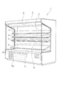
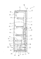
図1は、本実施形態にかかるショーケースの斜視図であり、図2は、ショーケースの側部断面図を示す。
本実施形態で説明する冷凍装置としてのショーケース1は、図1に示すように、前面が開放された多段オープン型のものであり、例えば、コンビニエンスストアなどの店舗に設置されて商品を冷却しながら陳列販売するための低温ショーケースである。このショーケース1は、図1及び図2に示すように、外側を構成するショーケース本体3と、このショーケース本体3の内部に設けられた略コ字形状の断熱壁部4と、この断熱壁部4のコ字形状の内側に設けられた内壁部5と、この内壁部5に取り付けられた複数段(本実施形態では4段)の陳列棚6とを備えている。
Hereinafter, an embodiment of the present invention will be described.
(First embodiment)
FIG. 1 is a perspective view of a showcase according to the present embodiment, and FIG. 2 is a side sectional view of the showcase.
As shown in FIG. 1, a
断熱壁部4と内壁部5との間には、図2に示すように、冷気が送流されるダクト7が形成されており、このダクト7の内部には、空気を冷却するための冷却器8と、この冷却器8の下方に配置され、冷却器8に向けて上方へ空気(冷気)を送る送風機9とが配置されている。
また、ショーケース1の上側には、ダクト7の上側端部と接続された冷気吹出口10が形成される一方、下側には、ダクト7の下側端部と接続された冷気吸込口11が形成されている。これにより、送風機9で送られた空気が冷却器8で冷却された後に上側へ送流され、冷気吹出口10から陳列棚6の付近へ放出される一方、陳列棚6の付近の冷気は、冷気吸込口11からダクト7内へ吸い込まれ、再び送風機9で冷却器8へ送流されるようになっている。この冷気の循環の流れを、図2中矢印12で示す。
As shown in FIG. 2, a
In addition, a
また、ショーケース1の下側部分であって、断熱壁部4の下方には機械室19が形成されており、この機械室19には、冷媒管13を介して冷却器8に接続される冷却ユニット20が配設され、これら冷却器8と冷却ユニット20とによって冷凍サイクルR(図3)が構成されている。
冷却ユニット20は、冷媒を圧縮する圧縮機14と、この圧縮機14で圧縮された高温、高圧のガス冷媒を冷却する放熱器15と、上記冷却器8で発生したドレン水を受ける第1ドレン皿23と、この第1ドレン皿23から流出したドレン水を受ける第2ドレン皿24とを備える。第1ドレン皿23は、第2ドレン皿24の上方に積層して配置され、放熱器15よりも機体背面側でユニットベース21上に載置されている。このユニットベース21の下方には、第2ドレン皿24から流出したドレン水を受けるメンテナンストレー25が配置されている。このメンテナンストレー25は、ユーザが引き出して溜まったドレン水を排出するためのものであり、本構成では、メンテナンストレー25に所定量を超えたドレン水が溜まると、その旨をユーザに報知するようになっている。
放熱器15と第1ドレン皿23及び第2ドレン皿24との間には送風機22が配置されており、この送風機22の運転により、放熱器15は、図1に示すように、前面パネル16の吸気穴16aから取り込んだ外気によって冷却される。放熱器15を冷却した空気は、図2に示すように、第1ドレン皿23及び第2ドレン皿24上を通過した後、ショーケース本体3と断熱壁部4との間を通過して上方の排出口17から外部へ排出されることになる。この外部空気の流れを図2中矢印18で示す。
In addition, a
The
A
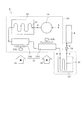
次に、ショーケース1の冷凍サイクルRについて説明する。
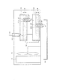
図3は、冷凍サイクルRを示す冷媒回路図である。
冷凍サイクルRは、図3に示すように、圧縮機14と放熱器15と膨張弁(減圧装置)26及び冷却器8を冷媒配管で順次接続して形成されており、圧縮機14と放熱器15との間に設けられたと吐出配管部31と、放熱器15と膨張弁(減圧手段)26との間に設けられた冷却対象部としての放熱器15の出口配管部32とを備える。
この出口配管部32は、並設された複数の直管部と、これら直管部を1パスに連結する曲管部とを備えて蛇行するように形成され、第1ドレン皿23上に配置されている。また、吐出配管部31は、出口配管部32と同様に、並設された複数の直管部と、これら直管部を1パスに連結する曲管部とを備えて蛇行するように形成され、第2ドレン皿24上に配置されている。この図3では、作図の便宜上、出口配管部32を吐出配管部31から離れた位置に記載しているが、本実施形態では、出口配管部32及び吐出配管部31は、それぞれ第1ドレン皿23及び第2ドレン皿24に配置された状態で上下に積層配置されている。
Next, the refrigeration cycle R of the
FIG. 3 is a refrigerant circuit diagram showing the refrigeration cycle R.
As shown in FIG. 3, the refrigeration cycle R is formed by sequentially connecting a
The
また、本実施形態では、放熱器15は、圧縮機14から吐出された高温の冷媒が流入する高温側放熱器15Aと、この高温側放熱器15Aの冷媒下流側に直列に接続され、当該高温側放熱器15Aに流入する冷媒よりも低温の低温側放熱器15Bとを備え、上記出口配管部32は、低温側放熱器15Bの出口側に設けられている。
また、高温側放熱器15A及び低温側放熱器15Bは、ショーケース1のユニットベース21の前面側に並設され、高温側放熱器15Aの風下側に第1ドレン皿23及び第2ドレン皿24が配置され、低温側放熱器15Bの風下側に圧縮機14が配置されている。
この構成によれば、第1ドレン皿23及び第2ドレン皿24は、高温側放熱器15Aの風下側に配置されるため、第1ドレン皿23及び第2ドレン皿24には、当該高温側放熱器15Aで熱交換した高温の空気が送風される。このため、第1ドレン皿23及び第2ドレン皿24に溜まったドレン水は、この高温の空気と接触することにより、当該ドレン水の蒸発の促進を図ることができる。
また、圧縮機14は、低温側放熱器15Bの風下側に配置されているため、この低温側放熱器15Bで熱交換した空気は、上記高温側放熱器15Aで熱交換した空気よりも低温となる。このため、この低温の空気を圧縮機14に向けて送風することにより、この圧縮機14が十分に冷却される。なお、上記したように、高温側放熱器15Aで熱交換した空気は高温となるため、この高温側放熱器15Aに送風する送風機22Aは、当該高温側放熱器15Aの風上側に設け、モータ等の保護を図っている。
In the present embodiment, the
Further, the high-
According to this configuration, since the
Further, since the
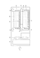
次に、第1ドレン皿23及び第2ドレン皿24の配置構成について説明する。
図4は、各ドレン皿への空気の流れを説明する側断面図であり、図5は、各ドレン皿へのドレン水の流れを示す側断面図である。この図4では、各ドレン皿にドレン水を排出するための排水管の記載を省略し、図5では、ドレン皿に配置される吐出配管部31及び出口配管部32の記載を省略している。
第1ドレン皿23は、図4に示すように、第2ドレン皿24と空気が通風可能な間隔を設け、不図示のブラケット等で固定することにより、当該第2ドレン皿24の上方に配置されている。第1ドレン皿23には、出口配管部32が、当該出口配管部32の直管部が機体の前後方向、すなわち通風方向に並ぶように配置され、出口配管部32の上方には、ドレン水蒸散板35が配置されている。このドレン水蒸散板35は、吸水性の素材で形成されており、第1ドレン皿23の上縁よりも上方に延在している。これにより、第1ドレン皿23に溜まったドレン水は、ドレン水蒸散板35によって吸い上げられるため、このドレン水蒸散板35で送風空気と接触することにより蒸発される。また、第2ドレン皿24上の吐出配管部31の配置構成、及びドレン水蒸散板35については、第1ドレン皿23と同様であるため説明を省略する。
Next, the arrangement configuration of the
FIG. 4 is a side cross-sectional view illustrating the flow of air to each drain pan, and FIG. 5 is a side cross-sectional view illustrating the flow of drain water to each drain pan. In FIG. 4, the description of the drain pipe for discharging drain water to each drain pan is omitted, and in FIG. 5, the description of the
As shown in FIG. 4, the
また、第1ドレン皿23の上方には、図5に示すように、冷却器8で生じたドレン水を第1ドレン皿23に導く導水配管36が設けられ、この導水配管36を通じたドレン水は第1ドレン皿23上に溜まる。第1ドレン皿23の底面には、この第1ドレン皿23に溜まったドレン水を当該第1ドレン皿23の下方に配置された第2ドレン皿24に排出するための第1排水管37が設けられている。この第1排水管37は、導水配管36と上面視で重ならない位置に設けられており、第1排水管37の上端部37Aは、第1ドレン皿23の底面よりも高さHだけ高い位置に形成されている。これにより、第1ドレン皿23には、高さHに相当する量のドレン水を貯留することができ、この高さHを超える量のドレン水が流入した場合に、第1排水管37を通じて、第1ドレン皿23から第2ドレン皿24にオーバーフローする。
Further, as shown in FIG. 5, a
また、第2ドレン皿24の底面には、この第2ドレン皿24に溜まったドレン水をメンテナンストレー25に排出するための第2排水管38が設けられている。この第2排水管38は、上記第1排水管37と上面視で重ならない位置に設けられており、上記第1排水管37と同様に、第2排水管38の上端部38Aは、第2ドレン皿24の底面よりも高さHだけ高い位置に形成されている。これにより、第2ドレン皿24には、高さHに相当する量のドレン水を貯留することができ、この高さHを超える量のドレン水が流入した場合に、第2排水管38を通じて、第2ドレン皿24からメンテナンストレー25にオーバーフローする。このドレン水の流れを図5中矢印40で示す。
Further, a
次に、第1実施形態の作用について説明する。
図6は、上記冷凍サイクルRのp−h線図である。
この図6において、点Aは、圧縮機14出口、点Bは、低温側放熱器15B出口、点Cは、出口配管部32出口、点Dは、膨張弁26出口、点Eは、圧縮機14入口での各圧力Pとエンタルピhとの関係を示している。
上述のように、第1ドレン皿23上には、放熱器15の出口配管部32が配置される。この第1ドレン皿23には、通常、冷却器8から流下したドレン水が溜まるため、第1ドレン皿23上に出口配管部32を配置することにより、この出口配管部32を流れる冷媒を当該ドレン水の冷熱で過冷却することができる。ここで、冷却器8から流下したドレン水は、一般に、第1ドレン皿23周囲の雰囲気温度よりも低いため、ドレン水の冷熱を利用することにより、空冷するものに比べて、出口配管部32を流れる冷媒をより低温に冷却することができる。
このため、本実施形態によれば、第1ドレン皿23上に出口配管部32を配置したことにより、第1ドレン皿23に出口配管部32を配置しない場合に比べて、図6に示すように、差分Δhに相当するだけ冷却能力を向上させることができ、ドレン水の冷熱を利用して冷却効率の向上を図ることができる。
また、本実施形態では、第1ドレン皿23から流出したドレン水を受ける第2ドレン皿24上に圧縮機14の吐出配管部31を配置したことにより、第1ドレン皿23で出口配管部32と熱交換して温められたドレン水が溜まるため、第2ドレン皿24上に吐出配管部31を配置することにより、この吐出配管部31を流れる冷媒の温熱で当該第2ドレン皿24上のドレン水を更に温めることができる。これにより、送風機22の送風空気により、第2ドレン皿24上のドレン水の蒸発を促進させることができる。
更に、本実施形態によれば、第2ドレン皿24の上方に第1ドレン皿23を重ねて配置したため、これら第1ドレン皿23及び第2ドレン皿24をショーケース1の機械室19内にコンパクトに配置することができるため、ショーケース1の小型化を図ることができる。
Next, the operation of the first embodiment will be described.
FIG. 6 is a ph diagram of the refrigeration cycle R.
In FIG. 6, point A is the outlet of the
As described above, the
For this reason, according to this embodiment, as shown in FIG. 6 compared with the case where the
Further, in the present embodiment, the
Furthermore, according to the present embodiment, since the
(第2実施形態)
次に、第2実施形態にかかる冷凍サイクルR1について説明する。
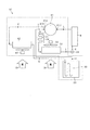
図7は、冷凍サイクルR1を示す冷媒回路である。
この冷凍サイクルR1は、図7に示すように、二段圧縮型の圧縮機41と、中間冷却器42とを備える点で上記冷凍サイクルRと構成を異にしている。この圧縮機41は、図示は省略するが、密閉容器内に配置される駆動要素としての電動要素と、この電動要素により駆動されて低圧のガス冷媒を中間圧まで圧縮して吐出する低段側圧縮部と、この低段側圧縮部で圧縮された中間圧のガス冷媒を冷却した後に再び密閉容器内に吸入し、高圧まで圧縮して吐出する高段側圧縮部とを備えて構成されている。
(Second Embodiment)
Next, the refrigeration cycle R1 according to the second embodiment will be described.
FIG. 7 is a refrigerant circuit showing the refrigeration cycle R1.
As shown in FIG. 7, the refrigeration cycle R1 is different from the refrigeration cycle R in that it includes a two-stage
圧縮機41の低段側圧縮部の吐出口41Aには、中間冷却器42の入口が接続され、この中間冷却器42の出口には、冷却対象部としての低段吐出配管部33が接続され、この低段吐出配管部33は、上記した第1ドレン皿23上に配置されている。また、低段吐出配管部33の出口は、圧縮機41の高段側圧縮部の吸込口41Bに接続されており、圧縮機41の低段側圧縮部で圧縮された中間圧の冷媒は、中間冷却器42、及び、第1ドレン皿23上に配置された低段吐出配管部33で冷却された後、上記吸込口41Bを通じて、高段側圧縮部に戻されるようになっている。
本実施形態では、中間冷却器42は、放熱器15と別体に形成し、この中間冷却器42に隣接して中間冷却器用送風機43を配置しているが、当該中間冷却器42を放熱器15と一体に形成して、これら中間冷却器42及び放熱器15を送風機22で空冷する構成としても良い。
An inlet of the
In this embodiment, the
また、高段側圧縮部の吐出口41Cには、上記した吐出配管部31、放熱器15、膨張弁26及び冷却器8が順次接続され、この冷却器8の出口は圧縮機41の低段側圧縮部の吸込口41Dに接続されている。また、吐出配管部31は、上記した第2ドレン皿24上に配置されている点は、上記第1実施形態と同様である。
Further, the
次に、第2実施形態の作用について説明する。
図8は、上記冷凍サイクルR1のp−h線図である。
この図8において、点Fは、圧縮機41の低段側圧縮部出口、点Gは、中間冷却器42出口、点Hは、低段吐出配管部33出口、点Iは、高段側圧縮部出口、点Jは、放熱器15出口、点Kは、膨張弁26出口、点Lは、圧縮機41の低段側圧縮部入口での各圧力Pとエンタルピhとの関係を示している。
上述のように、第1ドレン皿23上には、低段吐出配管部33が配置される。この第1ドレン皿23には、通常、冷却器8から流下したドレン水が溜まるため、第1ドレン皿23上に低段吐出配管部33を配置することにより、低段側圧縮部から吐出されて低段吐出配管部33を流れる中間圧力の冷媒を当該ドレン水の冷熱で中間冷却することができる。
これによれば、この第2実施形態によれば、第1ドレン皿23上に低段吐出配管部33を配置したことにより、第1ドレン皿23に低段吐出配管部33を配置しない場合に比べて、図8に示すように、差分Δh1に相当するだけ圧縮機41の高段側圧縮部の吸込口41Bでのエンタルピhを低減することができる。このため、高段側圧縮部の吐出口41Cから吐出されるガス冷媒の吐出温度を低く抑えることができることにより、例えば、雰囲気温度が高い環境下においても、耐熱温度基準の低い潤滑油、構成部品(例えば、シール部材や圧縮機の駆動モータのモータ巻線等)を使用することができ、コストの低減を図ることができる。
Next, the operation of the second embodiment will be described.
FIG. 8 is a ph diagram of the refrigeration cycle R1.
In FIG. 8, point F is the outlet of the lower stage compression section of the
As described above, the low-stage
According to this, according to this 2nd Embodiment, when the low stage
次に別の実施形態について説明する。
上記した第1実施形態では、冷却ユニット20を内蔵したショーケース1について説明したが、別の実施形態では、冷却ユニット20がショーケース本体3(すなわち冷却器8)と別置きされた別置型ショーケースについて説明する。この種の別置型ショーケースでは、一般に、冷却器から流下したドレン水は、ドレンパンで受けた後に、排水口を通じて直接外部の排水配管に排水される。このため、別の実施形態では、排水されるドレン水の冷熱を積極的に利用する点に特徴を有する。
この構成では、図9に示すように、ショーケース本体内に冷却器から流下したドレン水を受けるドレンパン50を備え、このドレンパン50には、他の部分よりも深底に形成してドレン水を一時的に貯留可能な貯留部50Aが形成されている。そして、この貯留部50Aに上記した出口配管部32が配置されている。これによれば、第1実施形態と同様に、ドレン水の冷熱を利用して冷却効率の向上を図ることができる。この構成では、ドレンパン50は第1のドレン皿としての機能を有する。
また、この構成に限らず、図10に示すように、ドレンパン60の排水口61の下方に上記した第1ドレン皿23を設け、この第1ドレン皿23上に出口配管部32を配置する構成としても良い。この構成によっても、第1実施形態と同様に、ドレン水の冷熱を利用して冷却効率の向上を図ることができる。
Next, another embodiment will be described.
In the first embodiment described above, the
In this configuration, as shown in FIG. 9, a
In addition to this configuration, as shown in FIG. 10, the above-described
以上、本発明の一実施形態について説明したが、本発明はこれに限定されるものではなく、種々の変更実施が可能である。例えば、上記した第1実施形態では、放熱器15を高温側放熱器15Aと低温側放熱器15Bとを別個に配置する構成について説明したが、両者を一体に構成しても構わないのは勿論である。
また、上記実施形態では、第1ドレン皿23と第2ドレン皿24とを上下に重ねて配置する構成としたが、第1ドレン皿23から第2ドレン皿にドレン水が流れる構成であれば、これらドレン皿を並設しても良い。
As mentioned above, although one Embodiment of this invention was described, this invention is not limited to this, A various change implementation is possible. For example, in the above-described first embodiment, the configuration in which the high-
Moreover, in the said embodiment, although it was set as the structure which has arrange | positioned the
1 ショーケース(冷凍装置)
8 冷却器
9 送風機
14、41 圧縮機
15 放熱器
15A 高温側放熱器
15B 低温側放熱器
19 機械室
20 ユニットベース
22 送風機
23 第1ドレン皿
24 第2ドレン皿
25 メンテナンストレー
31 吐出配管部
32 出口配管部(冷却対象部)
33 低段吐出配管部(冷却対象部)
36 導水配管
37 第1排水管
38 第2排水管
42 中間冷却器
R、R1 冷凍サイクル
1 Showcase (refrigeration equipment)
8
33 Low-stage discharge piping (cooling target)
36
Claims (4)
前記冷却器から流下するドレン水を受ける第1ドレン皿と、この第1ドレン皿から流出したドレン水を受ける第2ドレン皿とを備え、
前記冷凍サイクル中の所定の冷却対象部を前記第1ドレン皿上に配置するとともに、前記圧縮機の吐出配管を前記第2ドレン皿上に配置したことを特徴とする冷凍装置。 In a refrigeration apparatus comprising a compressor, a radiator, a decompression means and a cooler to constitute a refrigeration cycle
A first drain pan that receives drain water flowing down from the cooler, and a second drain pan that receives drain water flowing out of the first drain pan,
A refrigeration apparatus characterized in that a predetermined cooling target portion in the refrigeration cycle is disposed on the first drain pan, and a discharge pipe of the compressor is disposed on the second drain pan.
Priority Applications (1)
| Application Number | Priority Date | Filing Date | Title |
|---|---|---|---|
| JP2008240307A JP5322551B2 (en) | 2008-09-19 | 2008-09-19 | Refrigeration equipment |
Applications Claiming Priority (1)
| Application Number | Priority Date | Filing Date | Title |
|---|---|---|---|
| JP2008240307A JP5322551B2 (en) | 2008-09-19 | 2008-09-19 | Refrigeration equipment |
Publications (2)
| Publication Number | Publication Date |
|---|---|
| JP2010071572A true JP2010071572A (en) | 2010-04-02 |
| JP5322551B2 JP5322551B2 (en) | 2013-10-23 |
Family
ID=42203537
Family Applications (1)
| Application Number | Title | Priority Date | Filing Date |
|---|---|---|---|
| JP2008240307A Expired - Fee Related JP5322551B2 (en) | 2008-09-19 | 2008-09-19 | Refrigeration equipment |
Country Status (1)
| Country | Link |
|---|---|
| JP (1) | JP5322551B2 (en) |
Cited By (4)
| Publication number | Priority date | Publication date | Assignee | Title |
|---|---|---|---|---|
| JP2014035136A (en) * | 2012-08-09 | 2014-02-24 | Mitsubishi Electric Corp | Showcase |
| WO2015104952A1 (en) * | 2014-01-08 | 2015-07-16 | 東芝キヤリア株式会社 | Open showcase |
| JP2018185062A (en) * | 2017-04-24 | 2018-11-22 | ホシザキ株式会社 | Cooling storage |
| JP2020016391A (en) * | 2018-07-25 | 2020-01-30 | ダイキン工業株式会社 | Heat source unit of freezer |
Citations (6)
| Publication number | Priority date | Publication date | Assignee | Title |
|---|---|---|---|---|
| JPS55150981U (en) * | 1979-04-18 | 1980-10-30 | ||
| JPS55166383U (en) * | 1979-05-18 | 1980-11-29 | ||
| JPS5650988U (en) * | 1979-09-27 | 1981-05-06 | ||
| JPS61156883U (en) * | 1985-03-20 | 1986-09-29 | ||
| JP2002295958A (en) * | 2001-03-29 | 2002-10-09 | Sanyo Electric Co Ltd | Drain treating device for cooling device |
| JP2004085105A (en) * | 2002-08-27 | 2004-03-18 | Sanyo Electric Co Ltd | Refrigerator |
-
2008
- 2008-09-19 JP JP2008240307A patent/JP5322551B2/en not_active Expired - Fee Related
Patent Citations (6)
| Publication number | Priority date | Publication date | Assignee | Title |
|---|---|---|---|---|
| JPS55150981U (en) * | 1979-04-18 | 1980-10-30 | ||
| JPS55166383U (en) * | 1979-05-18 | 1980-11-29 | ||
| JPS5650988U (en) * | 1979-09-27 | 1981-05-06 | ||
| JPS61156883U (en) * | 1985-03-20 | 1986-09-29 | ||
| JP2002295958A (en) * | 2001-03-29 | 2002-10-09 | Sanyo Electric Co Ltd | Drain treating device for cooling device |
| JP2004085105A (en) * | 2002-08-27 | 2004-03-18 | Sanyo Electric Co Ltd | Refrigerator |
Cited By (7)
| Publication number | Priority date | Publication date | Assignee | Title |
|---|---|---|---|---|
| JP2014035136A (en) * | 2012-08-09 | 2014-02-24 | Mitsubishi Electric Corp | Showcase |
| WO2015104952A1 (en) * | 2014-01-08 | 2015-07-16 | 東芝キヤリア株式会社 | Open showcase |
| CN105992535A (en) * | 2014-01-08 | 2016-10-05 | 东芝开利株式会社 | Open showcase |
| JPWO2015104952A1 (en) * | 2014-01-08 | 2017-03-23 | 東芝キヤリア株式会社 | Open showcase |
| JP2019074308A (en) * | 2014-01-08 | 2019-05-16 | 東芝キヤリア株式会社 | Open showcase |
| JP2018185062A (en) * | 2017-04-24 | 2018-11-22 | ホシザキ株式会社 | Cooling storage |
| JP2020016391A (en) * | 2018-07-25 | 2020-01-30 | ダイキン工業株式会社 | Heat source unit of freezer |
Also Published As
| Publication number | Publication date |
|---|---|
| JP5322551B2 (en) | 2013-10-23 |
Similar Documents
| Publication | Publication Date | Title |
|---|---|---|
| US20070214823A1 (en) | Heat exchanging device for refrigerator | |
| JP5322551B2 (en) | Refrigeration equipment | |
| JP2009079778A (en) | Refrigerator | |
| JP4033219B2 (en) | vending machine | |
| WO2006031002A1 (en) | Continuously operating type showcase | |
| JP2007078228A (en) | Cold air circulation type show case | |
| WO2008147007A1 (en) | Refrigerating system | |
| JP2018048799A (en) | refrigerator | |
| JP5405158B2 (en) | Evaporator | |
| JP5139093B2 (en) | Cooling system | |
| JP2009236446A (en) | Showcase | |
| JP2009097756A (en) | Refrigerating device | |
| JP5340587B2 (en) | Showcase | |
| JP5157418B2 (en) | vending machine | |
| JP3941833B2 (en) | vending machine | |
| JP4666956B2 (en) | Cooling storage | |
| JP2010071540A (en) | Showcase | |
| JP4440069B2 (en) | Cooling and heating system and vending machine using it | |
| JP2010078167A (en) | Showcase | |
| JP2007017057A (en) | Cooling chamber | |
| JP2011247501A (en) | Cold air circulation type showcase | |
| JPH09269179A (en) | Defroster for refrigerator | |
| JP4513707B2 (en) | vending machine | |
| JP2010043757A (en) | Refrigerant circuit device | |
| JP2006300454A (en) | Low temperature showcase |
Legal Events
| Date | Code | Title | Description |
|---|---|---|---|
| A621 | Written request for application examination |
Free format text: JAPANESE INTERMEDIATE CODE: A621 Effective date: 20110912 |
|
| A977 | Report on retrieval |
Free format text: JAPANESE INTERMEDIATE CODE: A971007 Effective date: 20121218 |
|
| A131 | Notification of reasons for refusal |
Free format text: JAPANESE INTERMEDIATE CODE: A131 Effective date: 20130108 |
|
| A521 | Written amendment |
Free format text: JAPANESE INTERMEDIATE CODE: A523 Effective date: 20130306 |
|
| RD02 | Notification of acceptance of power of attorney |
Free format text: JAPANESE INTERMEDIATE CODE: A7422 Effective date: 20130306 |
|
| TRDD | Decision of grant or rejection written | ||
| A01 | Written decision to grant a patent or to grant a registration (utility model) |
Free format text: JAPANESE INTERMEDIATE CODE: A01 Effective date: 20130618 |
|
| A61 | First payment of annual fees (during grant procedure) |
Free format text: JAPANESE INTERMEDIATE CODE: A61 Effective date: 20130716 |
|
| LAPS | Cancellation because of no payment of annual fees |