JP2010071465A - Quick connector coupling with lateral stabilization - Google Patents
Quick connector coupling with lateral stabilization Download PDFInfo
- Publication number
- JP2010071465A JP2010071465A JP2009198134A JP2009198134A JP2010071465A JP 2010071465 A JP2010071465 A JP 2010071465A JP 2009198134 A JP2009198134 A JP 2009198134A JP 2009198134 A JP2009198134 A JP 2009198134A JP 2010071465 A JP2010071465 A JP 2010071465A
- Authority
- JP
- Japan
- Prior art keywords
- tube
- stabilizing ring
- ring
- quick connector
- stabilization
- Prior art date
- Legal status (The legal status is an assumption and is not a legal conclusion. Google has not performed a legal analysis and makes no representation as to the accuracy of the status listed.)
- Pending
Links
- 230000006641 stabilisation Effects 0.000 title claims abstract description 68
- 238000011105 stabilization Methods 0.000 title claims abstract description 68
- 230000008878 coupling Effects 0.000 title claims abstract description 39
- 238000010168 coupling process Methods 0.000 title claims abstract description 39
- 238000005859 coupling reaction Methods 0.000 title claims abstract description 39
- 238000007789 sealing Methods 0.000 claims abstract description 17
- 239000012530 fluid Substances 0.000 claims abstract description 16
- 230000000087 stabilizing effect Effects 0.000 claims description 56
- 230000002093 peripheral effect Effects 0.000 claims description 16
- 238000000034 method Methods 0.000 claims description 14
- 239000000463 material Substances 0.000 claims description 5
- 229910052751 metal Inorganic materials 0.000 claims description 3
- 239000002184 metal Substances 0.000 claims description 3
- 230000000295 complement effect Effects 0.000 claims 1
- 230000007246 mechanism Effects 0.000 description 9
- 230000008569 process Effects 0.000 description 8
- 238000012795 verification Methods 0.000 description 6
- 239000004033 plastic Substances 0.000 description 4
- 238000006073 displacement reaction Methods 0.000 description 2
- 230000004048 modification Effects 0.000 description 2
- 238000012986 modification Methods 0.000 description 2
- 239000004952 Polyamide Substances 0.000 description 1
- 239000000853 adhesive Substances 0.000 description 1
- 230000001070 adhesive effect Effects 0.000 description 1
- 238000004378 air conditioning Methods 0.000 description 1
- 229910052782 aluminium Inorganic materials 0.000 description 1
- XAGFODPZIPBFFR-UHFFFAOYSA-N aluminium Chemical compound [Al] XAGFODPZIPBFFR-UHFFFAOYSA-N 0.000 description 1
- 230000008859 change Effects 0.000 description 1
- 238000012790 confirmation Methods 0.000 description 1
- 239000013013 elastic material Substances 0.000 description 1
- 239000000446 fuel Substances 0.000 description 1
- 238000003780 insertion Methods 0.000 description 1
- 230000037431 insertion Effects 0.000 description 1
- 238000009434 installation Methods 0.000 description 1
- 230000014759 maintenance of location Effects 0.000 description 1
- 230000035515 penetration Effects 0.000 description 1
- 229920002647 polyamide Polymers 0.000 description 1
- 229920000642 polymer Polymers 0.000 description 1
Images


Classifications
-
- F—MECHANICAL ENGINEERING; LIGHTING; HEATING; WEAPONS; BLASTING
- F16—ENGINEERING ELEMENTS AND UNITS; GENERAL MEASURES FOR PRODUCING AND MAINTAINING EFFECTIVE FUNCTIONING OF MACHINES OR INSTALLATIONS; THERMAL INSULATION IN GENERAL
- F16L—PIPES; JOINTS OR FITTINGS FOR PIPES; SUPPORTS FOR PIPES, CABLES OR PROTECTIVE TUBING; MEANS FOR THERMAL INSULATION IN GENERAL
- F16L37/00—Couplings of the quick-acting type
- F16L37/08—Couplings of the quick-acting type in which the connection between abutting or axially overlapping ends is maintained by locking members
- F16L37/12—Couplings of the quick-acting type in which the connection between abutting or axially overlapping ends is maintained by locking members using hooks, pawls, or other movable or insertable locking members
- F16L37/14—Joints secured by inserting between mating surfaces an element, e.g. a piece of wire, a pin, a chain
- F16L37/142—Joints secured by inserting between mating surfaces an element, e.g. a piece of wire, a pin, a chain where the securing element is inserted tangentially
- F16L37/144—Joints secured by inserting between mating surfaces an element, e.g. a piece of wire, a pin, a chain where the securing element is inserted tangentially the securing element being U-shaped
-
- F—MECHANICAL ENGINEERING; LIGHTING; HEATING; WEAPONS; BLASTING
- F16—ENGINEERING ELEMENTS AND UNITS; GENERAL MEASURES FOR PRODUCING AND MAINTAINING EFFECTIVE FUNCTIONING OF MACHINES OR INSTALLATIONS; THERMAL INSULATION IN GENERAL
- F16L—PIPES; JOINTS OR FITTINGS FOR PIPES; SUPPORTS FOR PIPES, CABLES OR PROTECTIVE TUBING; MEANS FOR THERMAL INSULATION IN GENERAL
- F16L37/00—Couplings of the quick-acting type
- F16L37/08—Couplings of the quick-acting type in which the connection between abutting or axially overlapping ends is maintained by locking members
- F16L37/084—Couplings of the quick-acting type in which the connection between abutting or axially overlapping ends is maintained by locking members combined with automatic locking
- F16L37/088—Couplings of the quick-acting type in which the connection between abutting or axially overlapping ends is maintained by locking members combined with automatic locking by means of a split elastic ring
- F16L37/0885—Couplings of the quick-acting type in which the connection between abutting or axially overlapping ends is maintained by locking members combined with automatic locking by means of a split elastic ring with access to the split elastic ring from a radial or tangential opening in the coupling
-
- F—MECHANICAL ENGINEERING; LIGHTING; HEATING; WEAPONS; BLASTING
- F16—ENGINEERING ELEMENTS AND UNITS; GENERAL MEASURES FOR PRODUCING AND MAINTAINING EFFECTIVE FUNCTIONING OF MACHINES OR INSTALLATIONS; THERMAL INSULATION IN GENERAL
- F16L—PIPES; JOINTS OR FITTINGS FOR PIPES; SUPPORTS FOR PIPES, CABLES OR PROTECTIVE TUBING; MEANS FOR THERMAL INSULATION IN GENERAL
- F16L2201/00—Special arrangements for pipe couplings
- F16L2201/10—Indicators for correct coupling
Landscapes
- Engineering & Computer Science (AREA)
- General Engineering & Computer Science (AREA)
- Mechanical Engineering (AREA)
- Quick-Acting Or Multi-Walled Pipe Joints (AREA)
Abstract
Description
本発明は、クイックコネクタ継手を含む流体管路系、より詳細には、関連する継手部品間の軸方向の安定を有するクイックコネクタ継手に関する。 The present invention relates to a fluid line system including a quick connector coupling, and more particularly to a quick connector coupling having axial stability between associated coupling components.
自動車分野及び他の分野では、メスコネクタ本体内に受け取られて密封保持されるオス部材を概して含むクイックコネクタ継手が、2つの部品又は導管間に流体接続を提供するためにしばしば用いられ、そのため、2つの部品間に流体管路が確立する。クイックコネクタ継手の使用は、密封固定された流体管路を最小限の時間及び費用で確立することができるという点において有利である。 In the automotive and other fields, quick connector couplings that generally include a male member received and sealed within a female connector body are often used to provide a fluid connection between two parts or conduits, and therefore A fluid line is established between the two parts. The use of a quick connector coupling is advantageous in that a hermetically sealed fluid line can be established with minimal time and expense.
クイックコネクタ継手のオス部材及びメスコネクタ本体を固定するために、多くの方法及び機構が存在する。1つのタイプの保持機構は、コネクタ本体の外側に形成されているスロットに挿入されるリテーナの使用を伴う。スロット内を延びるビーム(beam)が、オス部材の拡径部分と、スロットを画定する後面との間で当接した状態で位置付けられ、管が抜けるのを防止する。そのようなリテーナは多くの場合「馬蹄形」リテーナと称される。このタイプの継手の例は、特許文献1及び特許文献2に見られる。 There are many methods and mechanisms for securing the male and female connector bodies of the quick connector joint. One type of retention mechanism involves the use of a retainer that is inserted into a slot formed on the outside of the connector body. A beam extending through the slot is positioned in contact between the enlarged portion of the male member and the rear surface defining the slot to prevent the tube from escaping. Such retainers are often referred to as “horse-shoe” retainers. Examples of this type of joint can be found in US Pat.
そのような継手では、管の端部と、入口開口の前方から離間した内孔の管受け取り部分との接触を導くことを除いて、管は支持されない。管に対する、すなわち継手の軸方向の範囲に対して横方向である横力によって、管と本体との間の密封完全性が低下し、浸透損失(permeation loss)が増大する可能性がある。また、挿入される管端部の形は、継手本体内で回転可能なものである。 In such a joint, the tube is not supported except for directing contact between the end of the tube and the tube receiving portion of the bore spaced from the front of the inlet opening. Lateral forces on the tube, i.e., transverse to the axial extent of the joint, can reduce the sealing integrity between the tube and the body and increase permeation loss. Further, the shape of the inserted tube end is rotatable within the joint body.
一実施の形態では、本開示の継手は、入口開口においてコネクタ本体と管との間に介在する安定化リングを含む。安定化リングは、アルミニウム又はプラスチック等の剛性材料から成り得る。安定化リングは、たとえば安定化リング内での管の膨張によって、オス部材の管状部分の周囲に堅く接続することができる。 In one embodiment, the joint of the present disclosure includes a stabilizing ring interposed between the connector body and the tube at the inlet opening. The stabilizing ring can be made of a rigid material such as aluminum or plastic. The stabilization ring can be rigidly connected around the tubular portion of the male member, for example by expansion of the tube within the stabilization ring.
安定化リングは、入口開口において継手本体のリテーナ部分に取り外し可能に受け取られ、管の外面と協働して管の長手方向の範囲に対して横方向の支持を提供する。安定化リングは、管とコネクタ本体との間の側面荷重性能を向上させる。本体及び管を軸方向に位置合わせした状態で維持することによって、内側流体シールに対する側面荷重が低下し、浸透損失が低減する。 A stabilizing ring is removably received in the retainer portion of the fitting body at the inlet opening and cooperates with the outer surface of the tube to provide lateral support for the longitudinal extent of the tube. The stabilizing ring improves the side load performance between the tube and the connector body. By maintaining the body and tube in axial alignment, the side load on the inner fluid seal is reduced and permeation loss is reduced.
安定化リングは、本体内孔と管の外面との間の、管の長手方向軸を中心とした相対回転運動に抵抗することもできる。このような相対運動の最小化によって、さらに浸透損失に抵抗する強固な密封を確実にする。このような相対運動の最小化は、コネクタ継手本体に対する管又はオス部材の特定の回転方向も可能にする。 The stabilizing ring can also resist relative rotational movement about the longitudinal axis of the tube between the body bore and the outer surface of the tube. Such minimization of relative motion further ensures a tight seal that resists penetration loss. Such minimization of relative motion also allows for a specific direction of rotation of the tube or male member relative to the connector fitting body.
本開示のクイックコネクタ継手は、流体管路系と関連して示されている。クイックコネクタ継手は、剛性管と他の流体搬送部品、特にフレキシブルホースとの間の解放可能な接続部として示されている。しかし、継手には、加圧状態であっても又は加圧状態でなくても、流体経路の剛性要素の接続のような、流体密であるが解放可能な接続が望まれる多くの他の用途がある。例として、自動車の車両燃料送達システム又は自動車の空調システムが挙げられる。解放可能な流体コネクタ継手の一例を、2009年2月3日に特許付与された「Redundant Latch/Verifier for a Quick Connector」と題する米国特許第7,484,774号明細書(’774特許)に見出すことができ、該特許文献の明細書及び図面は、参照によりその全体が本明細書に援用される。 The quick connector coupling of the present disclosure is shown in connection with a fluid line system. The quick connector coupling is shown as a releasable connection between a rigid tube and other fluid carrying parts, in particular a flexible hose. However, many other applications where a fluid-tight but releasable connection is desired for the joint, such as connection of rigid elements in the fluid path, whether pressurized or not. There is. Examples include automotive vehicle fuel delivery systems or automotive air conditioning systems. An example of a releasable fluid connector coupling is disclosed in US Pat. No. 7,484,774 (the '774 patent), entitled “Redundant Latch / Verifier for a Quick Connector”, granted on February 3, 2009. The specification and drawings of that patent document are hereby incorporated by reference in their entirety.
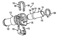
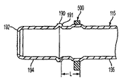
図1は、流体管路において切断可能な接続部を形成するクイックコネクタ継手110を示す。継手110は、主リテーナ部材116によって共に解放可能に固定される、実質的に円筒形のメスコネクタ本体112及びオス部材114から成る。冗長ラッチ/確認機構部材118を使用してもよい。多くの点で、クイックコネクタ継手110は、’774特許に開示されている構造と同様である。
FIG. 1 shows a quick connector coupling 110 that forms a severable connection in a fluid line. The coupling 110 comprises a substantially cylindrical
メスコネクタ本体112は、使用時に、同様に流体管路系の一部であるチューブ又はホース(図示せず)に接続される。メスコネクタ本体112及びオス部材114は、流体管路において恒久的であるが切断可能な接合部を形成するように接続可能である。
In use, the
図1に示されるように、オス部材114は、外側円筒形シール面194を有する剛性管115の端部に形成される。それは、管115の自由端部又は開端部192から所定距離を離して、後方向きの半径方向環状当接面191を画定する半径方向に拡大した拡径部分190を含む。管115の後方外側円筒面195が拡径部分190から後方に離れて延びる。
As shown in FIG. 1, the
コネクタ本体112が図1〜図5に示される。コネクタ本体112は中空であり、実質的に円筒形の壁120を含む。本体の外側は、本発明から逸脱せずに任意の所望の形状をとることができることを理解されたい。例えば、それは、コネクタ本体の一般的な形状であるように、端部間が90度曲がっていてもよい。
The
コネクタ本体は、ポリアミド等のプラスチック材料から成る別個に成形されたリテーナハウジング124に取り付けられる、金属製のステム部分122を含む。そのような構成は、2009年3月3日に特許付与された「Hybrid Quick Connector」と題する米国特許第7,497,480号明細書に開示されており、該特許文献の明細書及び図面が参照により本明細書に援用される。
The connector body includes a
図4を参照すると、壁120の内面は、オス部材受け取り端128にある入口開口127からホース接続端130までの貫通内孔126を画定する。軸方向及び軸方向にという用語は、本明細書で使用される場合、コネクタ本体の壁120に長手方向に沿うことを意味することに留意されたい。横方向、横方向に、横断方向及び横断方向にという用語は、本体の壁120の長手方向の範囲に対して実質的に垂直な平面内にあることを意味する。
Referring to FIG. 4, the inner surface of the
コネクタ本体112の内孔126は、コネクタ本体112を貫通する。コネクタ本体112の壁120の直径の変化は、貫通内孔126を異なる複数のセクション、すなわち、リテーナハウジングセクション132、シール室134、及び管端部レセプタクル136に分ける。前方という用語は、オス部材受け取り端128から実質的に中心軸に沿ってホース接続端130へ向かう軸方向を意味するように、本明細書で使用されることに留意されたい。後方という用語は、ホース接続端130から実質的に中心軸に沿ってオス部材受け取り端128へ向かう軸方向を意味する。
The
リテーナハウジングセクション132は、オス部材受け取り端128に隣接している。リテーナハウジングセクション132は、オス受け取り端128において貫通内孔126への入口穴すなわち入口開口127を画定する、横断方向平面の後方向きの面129を有するリム140によって画定されている。リム140は、いくつかの支柱によって前方リム142に接続する。図3に見られるように、リム140と前方リム142との間の隙間に、主リテーナ116及び補助ラッチ確認機構118を受け取り、これらは既知の方法でオス部材114をコネクタ本体112の内孔126内に解放可能に固定するように動作する。
内孔126は、入口開口127において、軸方向に延びる安定化リング支持面139を画定する。内孔126は、本体116の入口開口127へのオス部材114の挿入時に、拡径部分190を通すようなサイズである。
The
軸方向に延びる安定化リング支持面139の形状は、図5において最もよく分かる。それは、以下で説明される安定化リング又はインサート500を受け取って支持するように構成される。軸方向面139は、円筒形部分又は弓状部分144を含む。それは、外方向延長キャビティ145の形状の一対のノッチ(notch)も画定する。それは、半径方向外方中央スロット146も画定する。
The shape of the axially extending stabilizing
管端部レセプタクル136は、リテーナハウジングセクション124に形成される円筒形の内孔面137、及びステム部分122内の同軸上の内孔面138によって形成される。管端部レセプタクル136は、オス部材114の管115の外側円筒面194を受け取り、これを導くか又は案内するようなサイズである。
図4を参照すると、シール室134は、リテーナハウジングセクション132の軸方向前方に形成される。それは、本体112の内孔127内の半径方向の環状壁151及び152と、ステム部分122内の軸方向の円筒面135とによって画定される。それは、コネクタ本体112とオス部材114との間に流体シールを形成するように、シール部材148を収容するようなサイズである。
With reference to FIG. 4, the
図3に示されるように、Oリング148の形状のシール部材は、シール室134内において、円筒面135に対してきつく嵌められるようなサイズであると共に、オス部材114を画定する管115の外側円筒形シール面194の周囲にきつく嵌められるようなサイズである。Oリング148は、半径方向の環状壁151及び152によってシール室134内に軸方向に制限される。
As shown in FIG. 3, the O-
流体通路138は、壁120の最小径部分によって画定される。それは、内孔126の残りを画定する。
The
明確にするために、クイックコネクタ継手110は、実質的に水平面に位置付けられる長手方向の範囲で示され、「上部」、「底部」、及び「側部」という用語は、コネクタ本体116を説明する際に使用してきたことを留意されたい。「上部」の構成は主リテーナ116に関連しており、底部の構成は冗長ラッチ/確認機構118に関連していることが理解されるであろう。しかし、コネクタ継手110は、使用時に、水平面及び垂直面に関係なくあらゆる向きをとることができ、「上部」及び「底部」は、本明細書での例示に関するものにすぎない。
For clarity, the quick connector coupling 110 is shown with a longitudinal extent positioned substantially in a horizontal plane, and the terms “top,” “bottom,” and “side” describe the
「馬蹄形」タイプの主リテーナ116は、図1〜図3に示されている。主リテーナ116は、プラスチック等の弾性がある可撓性材料から成形されるのが好ましい。リム140及び142間のリテーナハウジングセクション132の上部に横断方向に延びる主リテーナ116は、コネクタ本体112に取り外し可能に連結される。それは、一対の細長い実質的に平行に離間した脚部196を含む。脚部196は、横部材198に接合されると共にそれから延びる。横部材198は、オス部材114の円筒管115の外径に実質的に等しい距離の間隔を脚部196の間に提供する。横部材198を有する脚部196の構造によって脚部196が外側に拡張することができ、オス部材を挿入及び解放することを可能にする。脚部196は、ラッチ位置にあるとき、図3に示されるようにオス部材190の拡径部分190の後方半径方向環状当接面191と、リム140の前面との間で当接関係にある。脚部はそのように位置付けられると、オス部材114が本体112の内孔126から抜けるのを防止する。管115の円筒形シール面194は、円筒形の内孔137及び138内に配置され、Oリングシール部材148は、面194に対して密封する。内孔137及び138は、管115の外側円筒形シール面194よりもわずかに大きいサイズである。したがって、管は横方向の動きに対して支持される。
A “horse-shoe” type
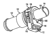
冗長ラッチ/確認機構118は、図1及び図2に示される。それは、上記で明記した米国特許第7,497,480号明細書に記載されているように構成される。
The redundant latch /
冗長ラッチ/確認機構118は、プラスチック等の弾性がある可撓性材料から成形される。冗長ラッチ/確認機構118は、リテーナハウジングセクション132の底部に位置する。それは、半径方向内側位置、すなわちラッチ位置と、半径方向外側位置、すなわちラッチ解除位置との間で、貫通内孔126に離接して、コネクタ本体112を横断するように摺動可能である。それは、ラッチ位置において、主リテーナ116が誤って開くのを防止する。用途によっては、それは、示されるように半径方向に摺動可能なロックビーム172を含むこともできる。ビーム172の面は、ラッチ位置において、拡径部分190の半径方向当接面191と当接して、管114がコネクタ本体112から抜けるのを防止する。
The redundant latch /
冗長ラッチ/確認機構118は、本明細書において例示の目的のみに示される。それは、本発明を具現するクイックコネクタ継手に必須の要素ではない。
The redundant latch /
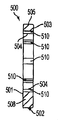
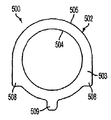
示される実施形態において、また図5〜図8において最もよく分かるように、継手110の安定化リング又はインサート500は、入口開口127の前方で管115とコネクタ本体112の間に位置すると共に、本体112に対する管115のためのさらなる横方向又は横断方向の支持を提供するように構成される。それは、前方平面501及び後方平面503間の短い軸方向の範囲の平面ディスク状要素である。特に、安定化リング500は左右対称である。したがって、設置時に、安定化リング500のどちらの平面が前方を向きどちらの面が後方を向くかに関して明確に方向付ける必要はない。
In the embodiment shown and best seen in FIGS. 5-8, the stabilizing ring or insert 500 of the fitting 110 is located between the
インサート500は、リテーナ部分132の軸方向に延びる安定化リング支持面139と協働する実質的に円筒形又は弓形のセグメント505を画定する、外周面502を含む。
The
リング500は、入口開口127において、管115の後方外側円筒面195と、リテーナ部分132の軸方向に延びる安定化リング支持面139との間の隙間を埋めるように構成される。リング500の外周面502は、軸方向に延びる安定化リング支持面139の形状を補完する形状を有する。それは、半径方向外方に延びると共に面139によって画定される外方向延長キャビティ145に係合するような形状である突出部508を含む。外周面502は、入口開口127において、軸方向面139によって画定される中央の半径方向スロット146内に位置する中央突出部509をさらに画定する。
The
外周面502は、安定化リング支持面139の外周よりもわずかに小さいサイズであり、そのためインサート500は、支持面139内にぴったりとではあるが制限されずに、嵌る。したがって、インサート500は、このような挿入に必要な相当量の軸方向力を一切必要とすることなく、軸方向に延びる安定化リング支持面内の位置へと軸方向前方に動くことができる。しかし、インサート500の外周面502は挿入されると、面139と協働して横方向又は横断方向の動きに抵抗する。
The outer
安定化リング500は、コネクタ本体116の入口開口127において、軸方向に延びる安定化リング支持面139によって画定される開口部へ挿入されると、本体116に対して安定化リング500の回転を防ぐように機能する。リング500の外側軸方向面502は、本体116の安定化リング支持面139内で支持される。リング500の突出部508及び509は、相対的な回転を防止するように本体116内の延長キャビティ145及びスロット146内に配置される。
The
安定化リング500は、管115の後方外側円筒面195と協働する内側軸方向面504によって画定される貫通内孔を含む。図1〜図8に示される実施形態では、安定化リング500の内側軸方向面504は、実質的に円筒形である。それは、管115の後方外側円筒面195の直径よりもわずかに大きい直径を有する。内側軸方向面504は、該面の周囲に離間した一連の半径方向外方ノッチ510を含む。ノッチ510は、管115の後方外側円筒面195と協働する。
安定化リング500の内側軸方向面504上のノッチ510は、拡径部分190の半径方向環状当接面191の後方で管115の後方外側円筒面195に係合する。安定化リング500は、管端部形成プロセス中に、管115の後方外側円筒面195に、拡径部分190から所定の適切な距離を離して取り付けられることが意図される。管115の端部及び半径方向拡径部分190に対するリング500の軸方向位置が最初に確立され、管は内部から膨張する。管115は半径方向外方に変形すると、ノッチ510に係合するようにいくらか変形して管の後方外側円筒面195を安定化リング500の内側軸方向面504に固定する。ノッチ510との係合は、リング500及び管115の把持関係をさらに強化する働きをする。
A
図9に示されるように、安定化リング500は、内側軸方向面504上に一切ノッチを形成しない中央内孔を含んでもよい。取り付けプロセス中、管115の後方外側円筒面195の膨張によって、安定化リング500を管115に摩擦固定する。
As shown in FIG. 9, the
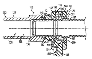
管115が完全に挿入されている、すなわち拡径部分190が主リテーナ116の脚部196の前方にある状態の図3に示されるように、安定化リング500は、入口開口127において、内孔126の軸方向に延びる安定化リング支持面139と係合するように位置付けられて、リング500に対する管114の回転を防ぐ。突出部508及び509は、外方向延長キャビティ145及び中央半径方向スロット146と係合してコネクタ本体116に対するリング500の回転を防ぐ。
As shown in FIG. 3 with the
図8を参照すると、管115の拡径部分190は、半径方向環状当接面191を管115の自由端部から所与の距離を離して配置するように形成される。この距離は、円筒形シール面194が管端部レセプタクル136の内孔面137及び138内で支持され、拡径部分190がリテーナ116の脚部196の前方に位置付けられるような距離である。
Referring to FIG. 8, the
インサート又は安定化リング500は、管115の後方外側円筒面195に固定され、後方平面503は後方半径方向環状当接面191から距離「L」を離して位置付けられ、そのため管が内孔126に完全に挿入された状態で、リング500は内側軸方向面139内に軸方向に位置合わせされるようになる。この関係によって、安定化リング500をコネクタ本体116内に配置し、前方平面501が入口開口127を画定する横断方向の後方向きの面129の前方にあり、外周面502が軸方向に延びる安定化リング支持面139と係合する。
The insert or stabilizing
管端部形成ステップ中に、安定化リング500が記載の固定位置において管115に取り付けられることが意図される。説明したように、安定化リング500は、管115の内部からの膨張によって管に固定され、後方外側円筒面195を内側円筒面504に摩擦係合させる。この膨張によって、安定化リング500のノッチ510と管115の後方外側円筒面195との間の把持関係も確立する。
It is contemplated that during the tube end forming step, the
次いで、正確に形成された拡径部分190及び正確に配置された安定化リング500を備えた管115は、クイックコネクタ継手組み付けプロセスの完了時に、入口開口127を通ってコネクタ本体112の内孔126内へ挿入することができる。
The
組み付けプロセスが完了すると、外側円筒形シール面194は、面137及び138によって画定される管端部レセプタクル136内に存在し、シール部材148は、内孔126の面135及び管115の外側円筒形シール面194に対して密封関係でシール室134内に存在する。拡径部分190は、半径方向環状当接面191がリテーナ116の脚部196の軸方向前方にあるように位置付けられる。安定化リング500は、外周面502が軸方向に延びる安定化リング支持面139内に位置合わせされるように配置される。このような、安定化リング500と本体112との間の後者の関係は、管115に支持を提供し、本体112に対する管115の横方向の変位に抵抗する。内側円筒面504の管115の後方外側円筒面195との固定された係合は、コネクタ本体112に対する管115の回転変位に抵抗する。
When the assembly process is complete, the outer
安定がないクイックコネクタ継手では、管115の自由端部は、内孔126の管受け取り部又はレセプタクル136へ導かれる。また、シール部材148は、シール室134において管の外側円筒面194及び内孔126の内側円筒面135と密封接触状態にあるため、本体の内孔126に対する管115の横方向又は横断方向の動きに対していくらか抵抗する。しかし、管端部レセプタクル136の後方にある、たとえば、オス部材受け取り端128にある入口開口127に隣接する、管115に対する横方向の支持はない。
In a quick connector coupling that is not stable, the free end of the
本発明の安定化リング500によって、安定化リング500の外側円筒面502は、入口開口127において本体の内孔126の内側の軸方向に延びる安定化リング支持面139に接触する。安定化リング500の内側円筒面504は、管115の後方外側円筒面195に接触する。管115のあらゆる横断方向の負荷は、管115から安定化リング500を通じてコネクタ本体116へ伝達する。この関係によって、継手が位置合わせの狂いに抵抗する性能が高まる。
With the
安定化リング500の内側円筒面504のサイズは、管115の拡径部分190を通すことはできないようなものであることに留意されたい。リング500は、拡径部分190を形成する端部形成プロセスの前に管115に適合させなければならない。代替的に、安定化リング500を、反対の端部から管115に組み付けて拡径部分190に隣接した位置へと摺動してもよい。
Note that the size of the inner
インサート又は安定化リング500を管115の後方外側円筒面195に固定してから、オス部材114をコネクタ本体112へ挿入する。リング500は、管115に対して回転可能ではないため、コネクタ本体に対する管の向きも固定される。この関係は、たとえばステム部分122が内孔126の長手方向軸に対して角度を成して形成される場合等、この回転関係を制御するのが重要である場合に有意である。
After the insert or stabilizing
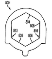
内側円筒面504は、安定化リング500に対する管115の回転に抵抗する任意の形状をとり得ることが意図される。たとえば、図10に示されるように、リング800の内側軸方向面804は、複数の平面部806によって画定される六角形パターンである。安定化リング800は、端部形成プロセス中に管115に適切に位置付けられこれに固定されることが意図される。平面部806の直径の距離は、管115の後方外側円筒面195の直径よりもわずかに大きいものである。端部形成プロセス中に、管115は、隣接する平面部806によって画定される複数の角810に向かって膨張する。したがって、管115は、安定化リング800に対する回転に逆らうように固定される。
It is contemplated that the inner
安定化リング500は、ポリマーゴムのような弾性材料から形成されることも意図される。安定化リング500には変形時、復元力をもたらすのに十分な弾性が備わっている。外側円筒面502は、入口開口127において、本体116の内孔126内に画定される内側の軸方向に延びる安定化リング支持面139よりもいくらか大きいサイズである。安定化リング500を挿入することによってリング500が半径方向に十分に変形し、内側円筒面502を管115の後方外側円筒面195に対して圧縮させ、これにより、リング500に対する管115の回転に抵抗する力を加える。管115の後方外側円筒面195と安定化リング500の内側軸方向面504との間に接着剤を塗布することもできる。
It is also contemplated that the
図11を参照すると、安定化リング500に対する管115の回転への抵抗を増大させる、管115の後方外側円筒面195の変更形態を示す。後方外側円筒面195は、複数の均等に離間した半径方向外向きのリッジ197又は管保持面を含む。これらのリッジは、インサート又は安定化リング500のノッチ510と位置合わせされると共に、ノッチ510内へ受け取られるように離間されている。リッジ197は、管の外部「ピンチング」、又は成形型内への管の膨張等の、任意の既知のプロセスによって管115に形成することができる。
Referring to FIG. 11, a modification of the rear outer
管115が完全に挿入されると、安定化リング500が拡径部分190の半径方向面191から距離「L」を離して且つ軸方向に延びる安定化リング支持面139内に配置されるように、リッジは拡径部分191に対して位置付けられる。
When the
Claims (22)
自由端部及び前記自由端部から離間している半径方向に拡大した拡径部分を有する管と、前記自由端部及び前記拡径部分の間に延びる円筒形シール面と、前記拡径部分の後方にある後方円筒面と、を備えるオス部材と、
前記管の前記後方円筒面を囲む安定化リングであって、前記軸方向に延びる安定化リング支持面内に配置される軸方向に延びる面を含む、安定化リングと、を備える、クイックコネクタ継手。 A connector body defining a through bore having an inlet opening at a male member receiving end, wherein the male member receiving end in front of the inlet opening defines an axially extending stabilizing ring support surface, the shaft A connector body further defining a tube end receptacle in front of the directionally extending stabilizing ring support surface;
A tube having a free end and a radially enlarged portion spaced apart from the free end, a cylindrical sealing surface extending between the free end and the enlarged portion, and A male member comprising a rear cylindrical surface at the rear;
A stabilization ring comprising a stabilization ring surrounding the rear cylindrical surface of the tube, the stabilization ring including an axially extending surface disposed within the axially extending stabilization ring support surface. .
前記安定化リングは、前記軸方向に延びる安定化リング支持面の形状を補完するような形状である外周面を含むと共に、前記軸方向に延びる安定化リング支持面内に制限されずにぴったり嵌るように構成される、請求項1に記載のクイックコネクタ継手。 The stabilizing ring support surface is configured to receive and support the stabilizing ring;
The stabilizing ring includes an outer peripheral surface that is shaped to complement the shape of the axially extending stabilizing ring support surface, and fits snugly within the axially extending stabilizing ring support surface without restriction. The quick connector coupling according to claim 1, configured as follows.
前記安定化リングの前記外周面は、前記少なくとも1つの延長キャビティ内に配置される少なくとも1つの突出部を画定する、請求項2に記載のクイックコネクタ継手。 The axially extending stabilizing ring support surface defines at least one outwardly extending cavity;
The quick connector coupling as claimed in claim 2, wherein the outer peripheral surface of the stabilization ring defines at least one protrusion disposed within the at least one extension cavity.
前記安定化リングの前記外周面は、各前記延長キャビティ内に配置される突出部を画定する、請求項3に記載のクイックコネクタ継手。 The axially extending stabilizing ring support surface defines a plurality of extended cavities;
The quick connector coupling as claimed in claim 3, wherein the outer peripheral surface of the stabilizing ring defines a protrusion disposed within each extension cavity.
前記継手は、前記リテーナハウジングセクション内に離間した脚部を有するリテーナを含み、
前記管の前記外側円筒シール面は、前記少なくとも1つの円筒形内孔面に配置され、
前記拡径部分は、前記脚部と当接関係にある後方半径方向環状当接面を含み、
前記安定化リングは、前方平面及び後方平面を含み、
前記前方平面が前記本体によって画定される前記入口開口の前方にあり、前記安定化リングの前記外周面が前記コネクタ本体の前記軸方向に延びる安定化リング支持面内にあるように、前記安定化リングは、前記後方半径方向環状当接面から距離「L」を離して配置される、請求項2に記載のクイックコネクタ継手。 The body includes at least one cylindrical bore surface defining the tube end receptacle and a retainer housing between the at least one cylindrical bore surface and the axially extending stabilizing ring support surface. Define sections,
The coupling includes a retainer having legs spaced apart in the retainer housing section;
The outer cylindrical sealing surface of the tube is disposed on the at least one cylindrical bore surface;
The enlarged diameter portion includes a rear radial annular contact surface in contact with the leg,
The stabilizing ring includes a front plane and a rear plane;
The stabilization is such that the front plane is in front of the inlet opening defined by the body, and the outer peripheral surface of the stabilization ring is in the axially extending stabilization ring support surface of the connector body. The quick connector coupling as claimed in claim 2, wherein the ring is located a distance “L” from the rear radial annular abutment surface.
前記安定化リングの前記外周面は、前記少なくとも1つの延長キャビティ内に配置される少なくとも1つの突出部を画定する、請求項13に記載のクイックコネクタ継手。 The axially extending stabilizing ring support surface defines at least one outwardly extending cavity;
The quick connector coupling as claimed in claim 13, wherein the outer peripheral surface of the stabilization ring defines at least one protrusion disposed within the at least one extension cavity.
前記安定化リングの前記外周面は、各前記延長キャビティ内に配置される突出部を画定する、請求項16に記載のクイックコネクタ継手。 The axially extending stabilizing ring support surface defines a plurality of extended cavities;
The quick connector coupling as claimed in claim 16, wherein the outer peripheral surface of the stabilization ring defines a protrusion disposed within each extension cavity.
自由端部及び外側円筒面を有する剛性管を提供するステップと、
外周面及び内側軸方向面を有する安定化リングを提供するステップと、
前記安定化リングを前記管の前記円筒面上に位置付けるステップと、
後方半径方向環状当接面を有する前記拡径部分を、前記管の前記自由端部から所与の距離を離して形成するステップと、
前記安定化リングを、前記後方環状当接面から所定の距離を離して位置付けるステップと、
前記安定化リングを前記後方円筒面に固定するために、前記管を膨張させるステップと、を含む、方法。 A method of forming a male member of a quick connector joint, wherein the male member has a rigid end having a free end portion and a radially enlarged portion spaced apart from the free end portion, and the free end portion And a cylindrical sealing surface extending between the enlarged diameter portion and a rear cylindrical surface behind the enlarged diameter portion, and a stabilizing ring is fixed to the rear cylindrical surface behind the enlarged diameter portion,
Providing a rigid tube having a free end and an outer cylindrical surface;
Providing a stabilizing ring having an outer peripheral surface and an inner axial surface;
Positioning the stabilizing ring on the cylindrical surface of the tube;
Forming the enlarged portion having a rear radial annular abutment surface at a given distance from the free end of the tube;
Positioning the stabilizing ring a predetermined distance away from the rear annular abutment surface;
Inflating the tube to secure the stabilization ring to the rear cylindrical surface.
前記管の前記後方円筒面を前記ノッチと係合させるために、前記管を膨張させるステップをさらに含む、請求項18に記載の方法。 The inner axial surface of the stabilizing ring is substantially cylindrical and includes a series of radially outward notches spaced about the surface;
The method of claim 18, further comprising inflating the tube to engage the posterior cylindrical surface of the tube with the notch.
安定化リングを提供すると共に、前記安定化リングを前記オス部材に固定し、
前記オス部材を前記管受け取り内孔内へ挿入し、
それによって、前記安定化リングを前記軸方向に延びる安定化リング支持面と係合させる、方法。 In a fluid coupling, a method of resisting relative rotation between a male member and a connector body having a tube receiving bore and defining an axially extending stabilizing ring support surface comprising:
Providing a stabilizing ring and securing the stabilizing ring to the male member;
Inserting the male member into the tube receiving bore;
Thereby, engaging the stabilizing ring with the axially extending stabilizing ring support surface.
前記安定化リング支持面によって前記コネクタ本体に画定される外方向延長キャビティを提供し、
さらに、前記延長キャビティ内に前記少なくとも1つの突出部を配置する、請求項20に記載の方法。 Providing at least one protrusion on the outer surface of the stabilizing ring;
Providing an outwardly extending cavity defined in the connector body by the stabilizing ring support surface;
21. The method of claim 20, further comprising disposing the at least one protrusion within the extension cavity.
Applications Claiming Priority (2)
| Application Number | Priority Date | Filing Date | Title |
|---|---|---|---|
| US9257208P | 2008-08-28 | 2008-08-28 | |
| US12/547,548 US20100052315A1 (en) | 2008-08-28 | 2009-08-26 | Quick connector coupling with lateral stabilization |
Publications (2)
| Publication Number | Publication Date |
|---|---|
| JP2010071465A true JP2010071465A (en) | 2010-04-02 |
| JP2010071465A5 JP2010071465A5 (en) | 2012-10-11 |
Family
ID=41606385
Family Applications (1)
| Application Number | Title | Priority Date | Filing Date |
|---|---|---|---|
| JP2009198134A Pending JP2010071465A (en) | 2008-08-28 | 2009-08-28 | Quick connector coupling with lateral stabilization |
Country Status (7)
| Country | Link |
|---|---|
| US (1) | US20100052315A1 (en) |
| JP (1) | JP2010071465A (en) |
| KR (1) | KR20100027026A (en) |
| CN (1) | CN101660642B (en) |
| BR (1) | BRPI0902706A2 (en) |
| DE (1) | DE102009038995A1 (en) |
| FR (1) | FR2935457A1 (en) |
Cited By (2)
| Publication number | Priority date | Publication date | Assignee | Title |
|---|---|---|---|---|
| WO2014097809A1 (en) * | 2012-12-20 | 2014-06-26 | 東海ゴム工業株式会社 | Piping connection structure |
| JP2017129231A (en) * | 2016-01-21 | 2017-07-27 | 株式会社Subaru | connector |
Families Citing this family (27)
| Publication number | Priority date | Publication date | Assignee | Title |
|---|---|---|---|---|
| CN102679073A (en) * | 2011-03-09 | 2012-09-19 | 苏州智泽电动工具有限公司 | Rapidly-plugging hose joint |
| WO2013031272A1 (en) * | 2011-08-29 | 2013-03-07 | 株式会社パイオラックス | Connector |
| JP5797547B2 (en) * | 2011-12-27 | 2015-10-21 | 株式会社ニフコ | connector |
| DE102012102256B4 (en) | 2012-03-16 | 2024-05-29 | Endress+Hauser Conducta Gmbh+Co. Kg | Analyzer with base module and exchangeable cassette |
| JP5674879B2 (en) * | 2013-08-05 | 2015-02-25 | 住友理工株式会社 | Quick connector |
| JP6438022B2 (en) | 2013-11-06 | 2018-12-12 | ベクトン ディキンソン アンド カンパニー リミテッド | System for sealed transfer of fluid including a locking member |
| DE102014103888A1 (en) * | 2014-03-21 | 2015-09-24 | Norma Germany Gmbh | Male coupling member |
| FR3021386B1 (en) | 2014-05-22 | 2017-02-24 | A Raymond Et Cie | TUBULAR CONNECTION WITH AUTOMATIC CONNECTION |
| FR3026814B1 (en) * | 2014-10-07 | 2017-04-14 | Caillau Ets | FAST CONNECTION TIP FOR A TUBE |
| CN104295836B (en) * | 2014-11-06 | 2016-03-02 | 重庆溯联汽车零部件有限公司 | A kind of for the mistake proofing of automobile pipeline system band, the quick release coupling confirming function |
| US10422459B2 (en) | 2015-01-14 | 2019-09-24 | Norma U.S. Holding Llc | Conduit connector with a primary and secondary latch |
| JP5885372B1 (en) | 2015-10-02 | 2016-03-15 | 株式会社ニチリン | connector |
| FR3044070B1 (en) * | 2015-11-20 | 2019-06-28 | A Raymond Et Cie | SAFETY TUBULAR CONNECTION WITH AUTOMATIC CONNECTION |
| EP3452747B1 (en) * | 2016-05-02 | 2020-10-14 | Nobel Gemlik Otomotiv San. Ve Tic. A.S. | Fuel filling line - fuel tank quick connection apparatus |
| US10415733B2 (en) * | 2016-08-17 | 2019-09-17 | Cooper-Standard Automotive Inc. | Quick connector |
| CN106641533B (en) * | 2017-02-17 | 2018-08-28 | 香河瑞和通汽车零部件有限公司 | A kind of automobile pipeline plastics quick connector having secondary locking mechanism |
| FR3064713B1 (en) | 2017-03-30 | 2020-07-17 | Akwel Sweden Ab | METHOD FOR MANUFACTURING A FLUIDIC ARRANGEMENT AND ASSOCIATED FLUIDIC ARRANGEMENT |
| FR3048052A1 (en) * | 2017-05-22 | 2017-08-25 | Parker Hannifin Mfg France Sas | CONNECTING DEVICE, METHOD AND TOOL FOR PLACING SUCH A DEVICE |
| FR3048051A1 (en) * | 2017-05-22 | 2017-08-25 | Parker Hannifin Mfg France Sas | CONNECTING DEVICE, METHOD AND TOOL FOR PLACING SUCH A DEVICE |
| DE102017006675B4 (en) * | 2017-07-14 | 2023-12-21 | A. Raymond Et Cie | Connector, system consisting of a connector and a locking pin having a head of a second component, method using such a system |
| USD859618S1 (en) * | 2017-09-15 | 2019-09-10 | Pentair Water Pool And Spa, Inc. | Heating apparatus clip |
| DK180026B1 (en) | 2018-03-12 | 2020-01-24 | Mbh-International A/S | A flexible double lumen tube and a tube coupling system for same |
| KR102108094B1 (en) * | 2018-10-04 | 2020-05-15 | 박성호 | A Connector For Air Mattress |
| CN112955688A (en) * | 2018-10-05 | 2021-06-11 | 胡安杰股份公司 | Fluid coupling system |
| US12129947B2 (en) | 2018-12-29 | 2024-10-29 | A. Raymond Et Cie | Quick connector |
| CN113483179B (en) * | 2021-07-05 | 2022-06-17 | 重庆溯联塑胶股份有限公司 | Mistake-proof double-locking quick connector |
| EP4269837A1 (en) * | 2022-04-26 | 2023-11-01 | Valeo eAutomotive Germany GmbH | Coupling assembly and transmission device comprising such a coupling assembly |
Citations (10)
| Publication number | Priority date | Publication date | Assignee | Title |
|---|---|---|---|---|
| JPS63146289U (en) * | 1987-03-17 | 1988-09-27 | ||
| JPH04107596U (en) * | 1991-03-01 | 1992-09-17 | シーケーデイ株式会社 | pipe fittings |
| JPH07260073A (en) * | 1994-03-24 | 1995-10-13 | Showa Alum Corp | Pipe connecting device |
| JPH08145256A (en) * | 1994-11-22 | 1996-06-07 | Kubota Corp | Coupling structure |
| JPH10110880A (en) * | 1996-10-04 | 1998-04-28 | Tokai Rubber Ind Ltd | Connecting structure body for connector and pipe |
| JPH10110881A (en) * | 1996-10-04 | 1998-04-28 | Tokai Rubber Ind Ltd | Connecting structure body for connector and pipe |
| JP2002013685A (en) * | 2000-05-17 | 2002-01-18 | Rasmussen Gmbh | Plug-in coupling type coupling device and plug-in coupling having such a coupling device |
| JP2005042794A (en) * | 2003-07-28 | 2005-02-17 | Togo Seisakusho Corp | Connector, and clamp guide and clamp used for the connector |
| JP2005172007A (en) * | 2003-12-05 | 2005-06-30 | Piolax Inc | Pipe joint |
| JP2008045563A (en) * | 2006-08-10 | 2008-02-28 | Aisin Seiki Co Ltd | Pipe joint |
Family Cites Families (35)
| Publication number | Priority date | Publication date | Assignee | Title |
|---|---|---|---|---|
| AT297424B (en) * | 1968-07-22 | 1972-03-27 | Industriebedarf Ges M B H | Pipe socket connection |
| US4691943A (en) * | 1985-04-24 | 1987-09-08 | Schmelzer Corporation | Quick connect fluid fitting assembly |
| US4875709A (en) * | 1988-02-26 | 1989-10-24 | Caroll James E | Controlled leak path |
| JPH0317026A (en) * | 1989-06-13 | 1991-01-25 | Agency Of Ind Science & Technol | Dehydrogenation |
| US5161833A (en) * | 1991-08-29 | 1992-11-10 | Huron Products Industries, Inc. | Positive transition quick connect coupling |
| US5324082A (en) * | 1991-08-29 | 1994-06-28 | Bundy Corporation | Positive transition quick connect coupling |
| US6086118A (en) * | 1991-09-10 | 2000-07-11 | Bundy Corporation | Quick connect tubing connector |
| US5257833A (en) * | 1991-09-25 | 1993-11-02 | Bundy Corporation | Metal retainer for quick connect tubing connector |
| US5395140A (en) * | 1993-05-13 | 1995-03-07 | Enhanced Applications, L.C. | Secondary latch and indicator for fluid coupling |
| US5988705A (en) * | 1993-05-24 | 1999-11-23 | Pilot Industries, Inc. | Quick connect coupling |
| FR2717883B1 (en) * | 1994-03-04 | 1996-06-14 | Hutchinson | Quick and watertight connection device for tubular pipes. |
| JP3467500B2 (en) * | 1994-03-29 | 2003-11-17 | 臼井国際産業株式会社 | Piping fittings |
| US5586792A (en) * | 1995-02-21 | 1996-12-24 | Bundy Corporation | Quick connector with integral release mechanism |
| US5628531A (en) * | 1995-04-26 | 1997-05-13 | Bundy Corporation | Quick connector with secondary latch |
| JP2880453B2 (en) * | 1996-06-07 | 1999-04-12 | 三桜工業株式会社 | Retainers for piping fittings |
| US5992902A (en) * | 1996-10-14 | 1999-11-30 | Masco Corporation Of Indiana | Device for the connection of a hydraulic apparatus to an external component |
| US5863077A (en) * | 1996-12-20 | 1999-01-26 | Itt Automotive, Inc. | Quick connector with snap-on frangible retainer |
| GB0011317D0 (en) * | 2000-05-10 | 2000-06-28 | John Guest International Limit | Tube couplings |
| US6508269B2 (en) * | 2000-12-27 | 2003-01-21 | Itt Manufacturing Enterprises, Inc. | Quick connector with one-way check valve |
| JP3958028B2 (en) * | 2001-01-15 | 2007-08-15 | 三桜工業株式会社 | Fitting for piping |
| JP4531288B2 (en) * | 2001-04-20 | 2010-08-25 | 株式会社東郷製作所 | connector |
| US6905143B2 (en) * | 2002-03-22 | 2005-06-14 | Itt Manufacturing Enterprises, Inc. | Fluid conduit quick connector and stuffer pack |
| DE50204467D1 (en) * | 2002-05-04 | 2006-02-16 | Ti Automotive Fuldabrueck Gmbh | Pipe coupling for pipelines |
| SE523474C2 (en) * | 2002-07-04 | 2004-04-20 | Weo Hydraulic Ab | Mounting stop on axially movable male-female couplings to prevent involuntary release of couplings |
| US6843516B2 (en) * | 2002-07-15 | 2005-01-18 | H-P Products, Inc. | Coupler for low pressure piping system |
| JP4055004B2 (en) * | 2002-09-30 | 2008-03-05 | 東海ゴム工業株式会社 | Detent for connector |
| JP4291989B2 (en) * | 2002-10-01 | 2009-07-08 | 株式会社パイオラックス | Piping connector |
| JP2004218832A (en) * | 2002-12-26 | 2004-08-05 | Usui Kokusai Sangyo Kaisha Ltd | Piping coupling |
| JP4041457B2 (en) * | 2003-12-12 | 2008-01-30 | 三桜工業株式会社 | Quick connector |
| US7156424B2 (en) * | 2004-03-05 | 2007-01-02 | Parker-Hannifin Corporation | Coupling assembly with retention mechanism |
| US7390025B2 (en) * | 2004-03-31 | 2008-06-24 | Ti Group Automotive Systems, Llc | Secondary latch/verifier for a quick connector |
| US7967342B2 (en) * | 2005-03-01 | 2011-06-28 | Ti Group Automotive Systems, Llc | Anti-rotation quick connector |
| US7455330B2 (en) * | 2005-04-28 | 2008-11-25 | Kulm Holding Ag | Quick coupling |
| US7484774B2 (en) * | 2005-05-03 | 2009-02-03 | Ti Group Automotive Systems, Llc | Redundant latch/verifier for a quick connector |
| US7497480B2 (en) * | 2006-04-07 | 2009-03-03 | Ti Group Automotive Systems, Llc | Hybrid quick connector |
-
2009
- 2009-08-26 US US12/547,548 patent/US20100052315A1/en not_active Abandoned
- 2009-08-27 BR BRPI0902706-8A patent/BRPI0902706A2/en not_active IP Right Cessation
- 2009-08-27 KR KR1020090079702A patent/KR20100027026A/en not_active Application Discontinuation
- 2009-08-27 FR FR0955848A patent/FR2935457A1/en not_active Withdrawn
- 2009-08-28 CN CN2009101715424A patent/CN101660642B/en not_active Expired - Fee Related
- 2009-08-28 DE DE102009038995A patent/DE102009038995A1/en not_active Withdrawn
- 2009-08-28 JP JP2009198134A patent/JP2010071465A/en active Pending
Patent Citations (10)
| Publication number | Priority date | Publication date | Assignee | Title |
|---|---|---|---|---|
| JPS63146289U (en) * | 1987-03-17 | 1988-09-27 | ||
| JPH04107596U (en) * | 1991-03-01 | 1992-09-17 | シーケーデイ株式会社 | pipe fittings |
| JPH07260073A (en) * | 1994-03-24 | 1995-10-13 | Showa Alum Corp | Pipe connecting device |
| JPH08145256A (en) * | 1994-11-22 | 1996-06-07 | Kubota Corp | Coupling structure |
| JPH10110880A (en) * | 1996-10-04 | 1998-04-28 | Tokai Rubber Ind Ltd | Connecting structure body for connector and pipe |
| JPH10110881A (en) * | 1996-10-04 | 1998-04-28 | Tokai Rubber Ind Ltd | Connecting structure body for connector and pipe |
| JP2002013685A (en) * | 2000-05-17 | 2002-01-18 | Rasmussen Gmbh | Plug-in coupling type coupling device and plug-in coupling having such a coupling device |
| JP2005042794A (en) * | 2003-07-28 | 2005-02-17 | Togo Seisakusho Corp | Connector, and clamp guide and clamp used for the connector |
| JP2005172007A (en) * | 2003-12-05 | 2005-06-30 | Piolax Inc | Pipe joint |
| JP2008045563A (en) * | 2006-08-10 | 2008-02-28 | Aisin Seiki Co Ltd | Pipe joint |
Cited By (4)
| Publication number | Priority date | Publication date | Assignee | Title |
|---|---|---|---|---|
| WO2014097809A1 (en) * | 2012-12-20 | 2014-06-26 | 東海ゴム工業株式会社 | Piping connection structure |
| JP2014122658A (en) * | 2012-12-20 | 2014-07-03 | Tokai Rubber Ind Ltd | Pipe connection structure |
| US10066773B2 (en) | 2012-12-20 | 2018-09-04 | Sumitomo Riko Company Limited | Piping connection structure |
| JP2017129231A (en) * | 2016-01-21 | 2017-07-27 | 株式会社Subaru | connector |
Also Published As
| Publication number | Publication date |
|---|---|
| KR20100027026A (en) | 2010-03-10 |
| US20100052315A1 (en) | 2010-03-04 |
| CN101660642B (en) | 2013-06-05 |
| FR2935457A1 (en) | 2010-03-05 |
| BRPI0902706A2 (en) | 2010-05-25 |
| DE102009038995A1 (en) | 2010-03-04 |
| CN101660642A (en) | 2010-03-03 |
Similar Documents
| Publication | Publication Date | Title |
|---|---|---|
| JP2010071465A (en) | Quick connector coupling with lateral stabilization | |
| JP5765887B2 (en) | Quick connector with seal assembly and retainer | |
| JP5301789B2 (en) | Hybrid quick joint | |
| JP5345446B2 (en) | Quick connector for high pressure applications | |
| US7128347B2 (en) | Passive transmitter for a quick connector | |
| JP5250224B2 (en) | Quick connector with conductive path | |
| JP4837458B2 (en) | Quick connector | |
| US7731245B2 (en) | Quick connector coupling | |
| JP2010038365A (en) | Quick connector joint with pull tab type retainer | |
| ES2742274T3 (en) | Quick connector | |
| US20050258646A1 (en) | Quick connector | |
| US8555480B2 (en) | Two part coupling connected by a clip | |
| US10094499B2 (en) | Quick-connect clip-on connector | |
| CN102124261A (en) | Connection made in two parts connected by a bayonet fitting, body part of such a connection and method of strengthening the coupling of body parts of such a connection | |
| JP6139126B2 (en) | Pipe connector | |
| JP4746388B2 (en) | Quick connector for high pressure applications | |
| US7055869B2 (en) | False insertion protection top hat for fluid quick connectors | |
| JP6525636B2 (en) | How to connect backup ring, fittings and pipes | |
| WO1993002313A1 (en) | Method and means for establishing a drawproof insertion joint between thin walled pipes | |
| EP1653143A1 (en) | Fluid quick connector with adapter | |
| PL163289B1 (en) | Pipe joint | |
| KR200497939Y1 (en) | Quick connector with verifier mechanism | |
| CN205036998U (en) | Detachable pipe fittings of two pipe end portions | |
| EP2976563B1 (en) | Pipe connector and system for connecting pipes | |
| JP2024024977A (en) | Pipe joint member and pipe joint |
Legal Events
| Date | Code | Title | Description |
|---|---|---|---|
| RD04 | Notification of resignation of power of attorney |
Free format text: JAPANESE INTERMEDIATE CODE: A7424 Effective date: 20120710 |
|
| A521 | Written amendment |
Free format text: JAPANESE INTERMEDIATE CODE: A523 Effective date: 20120824 |
|
| A621 | Written request for application examination |
Free format text: JAPANESE INTERMEDIATE CODE: A621 Effective date: 20120824 |
|
| A977 | Report on retrieval |
Free format text: JAPANESE INTERMEDIATE CODE: A971007 Effective date: 20130813 |
|
| A131 | Notification of reasons for refusal |
Free format text: JAPANESE INTERMEDIATE CODE: A131 Effective date: 20130820 |
|
| A131 | Notification of reasons for refusal |
Free format text: JAPANESE INTERMEDIATE CODE: A131 Effective date: 20140325 |
|
| A02 | Decision of refusal |
Free format text: JAPANESE INTERMEDIATE CODE: A02 Effective date: 20140814 |