JP2010070977A - Mechanism for providing screen in tensioned state - Google Patents
Mechanism for providing screen in tensioned state Download PDFInfo
- Publication number
- JP2010070977A JP2010070977A JP2008239684A JP2008239684A JP2010070977A JP 2010070977 A JP2010070977 A JP 2010070977A JP 2008239684 A JP2008239684 A JP 2008239684A JP 2008239684 A JP2008239684 A JP 2008239684A JP 2010070977 A JP2010070977 A JP 2010070977A
- Authority
- JP
- Japan
- Prior art keywords
- screen
- groove
- mounting groove
- lid
- bulging portion
- Prior art date
- Legal status (The legal status is an assumption and is not a legal conclusion. Google has not performed a legal analysis and makes no representation as to the accuracy of the status listed.)
- Granted
Links
Images


Abstract
Description
本発明は、スクリーン自体を直接的にサッシに対して簡易に固定できるようにしたスクリーン張設機構に関するものである。 The present invention relates to a screen extending mechanism that enables a screen itself to be directly and easily fixed to a sash.
従来、防虫、遮光、断熱、目隠し、花粉除け、あるいは装飾等のためのスクリーンを建物開口部に設置されたサッシ等に支持させて張設する場合、図13及び図14に示すように、スクリーン3を専用の枠部材41に予め張設して、それを独立の建具であるスクリーン固定枠40として取り扱い、あるいは開閉操作に供し得るようにして、窓等の戸障子2のサッシ1に固定的に、あるいは、開閉等のために摺動自在または着脱自在に取り付けている。しかしながら、近年のように、多くの住宅等の建物において、防虫、遮光等のための各種スクリーン3を建物開口部に張設し、しかも、人の出入りのない窓等のように、スクリーン自体を直接的にサッシ等に固定しても差し支えないところも少なくない場合には、上記スクリーン3を専用の枠部材41に固定してスクリーン固定枠40とする必要がなく、該スクリーン3をサッシに対して直接張設可能にするのが有利になる。
Conventionally, when a screen for insect prevention, light shielding, heat insulation, blindfolding, pollen repellent, or decoration is supported by a sash or the like installed in a building opening, as shown in FIG. 13 and FIG. 3 is preliminarily stretched on a
また、このようにスクリーン3をサッシに対して直接張設可能にするものとして、例えば、特許文献1に開示されているものなどが知られているが、このようなスクリーンは、季節によって交換し、あるいは、住宅の居住者らの趣向等に応じてスクリーンが選択張設されることが多いので、スクリーンの張設・撤去を居住者に任せることも多くなり、そのため、スクリーンの着脱が簡便で、熟練者でなくても容易に行えることが望ましく、しかも、見込・見付方向共に小さい寸法で簡易な構成のものとしてスクリーンの取付機構を実現し、スクリーンの張設に要する部材がサッシによって開かれている眺望を妨げない構成とすることも望まれる。
本発明の技術的課題は、スクリーン自体を直接的にサッシに固定するようにして、スクリーンの取付構造を簡素化するに当たり、スクリーンの張設、交換、撤去を、簡便で熟練者でなくても容易に行えるようにし、特に、スクリーンの張設は、工具等を用いることなく手作業のみで行うことを可能にし、しかも、一旦張設したスクリーンは離脱し難く、また、上記スクリーンをサッシ等における戸障子側に近い位置に設けられるスクリーン保護板に近接する位置に容易に配置することができて、スクリーンが戸障子に近い位置にスクリーン保護板により保護されて安定的に張設できるようにしたスクリーン張設機構を提供することにある。 The technical problem of the present invention is that the screen itself can be directly fixed to the sash to simplify the mounting structure of the screen. In particular, the screen can be stretched only by hand without using a tool, and the screen once stretched is not easily detached, and the screen is attached to a sash or the like. It can be easily placed near the screen protection plate provided near the door sliding door side, and the screen is protected by the screen protection plate near the door sliding door so that it can be stably stretched. It is to provide a screen extending mechanism.
上記課題を解決するため、本発明によれば、建物開口部に設置されるサッシにスクリーンを固定的に張設するためのスクリーン張設機構であって、上記サッシにおける縦横のスクリーン取付部には、スクリーンの取付溝を設け、上記スクリーンは、その四周に係止用の膨出部を付設したものとして構成し、上記スクリーンの取付溝に対してスクリーンの四周の係止用の膨出部を固定する固定手段は、該膨出部を係止させる係合溝を外面側に有する溝蓋、あるいは、該膨出部を上記取付溝の口縁との間に係止させる溝蓋に、それらを上記取付溝にスクリーンを挟圧することなく係合させる係合脚を設けることにより構成し、上記溝蓋には、上記係合脚を取付溝に押入係止させるための押圧板を備え、該押圧板に指先押圧用の平坦押圧面を備えていることを特徴とするスクリーン張設機構が提供される。
上記スクリーンの四周に付設する係止用の膨出部は、ファスナー半体により構成するのが望ましい。
In order to solve the above-described problems, according to the present invention, there is provided a screen extending mechanism for fixedly extending a screen to a sash installed in a building opening, and the vertical and horizontal screen mounting portions in the sash include The screen is provided with a mounting groove, and the screen is configured to be provided with a bulging portion for locking on the four sides of the screen, and the bulging portion for locking on the four sides of the screen with respect to the mounting groove of the screen. The fixing means for fixing the groove lid having an engaging groove for locking the bulging portion on the outer surface side, or the groove lid for locking the bulging portion between the rim of the mounting groove. The mounting groove is provided with an engaging leg that engages the screen without pinching the screen, and the groove cover is provided with a pressing plate for pressing and locking the engaging leg into the mounting groove, and the fingertip is attached to the pressing plate. With a flat pressing surface for pressing Screen stretched mechanism, wherein Rukoto is provided.
It is desirable that the locking bulges provided on the four circumferences of the screen are constituted by fastener halves.
本発明に係るスクリーン張設機構の好ましい実施形態においては、上記スクリーンの取付溝が、上記サッシにおけるスクリーン取付部に直接取付溝を形成し、あるいは当該取付溝を有する溝材をサッシに固定することにより構成される。
また、本発明に係るスクリーン張設機構の好ましい実施形態においては、上記取付溝が上記サッシにおける内側に向けて開口し、上記溝蓋における押圧板が、該溝蓋の係合脚を上記取付溝に押入できる向きに形成され、上記溝蓋の係合脚の上記取付溝に対する係合機構を、該係合脚の上記取付溝に対する係合を離脱させるに要する力が、上記押圧板の押圧による係合脚の取付溝への押入係止のための押圧力よりも大きいものとして構成される。
In a preferred embodiment of the screen extending mechanism according to the present invention, the mounting groove of the screen forms a mounting groove directly in the screen mounting portion of the sash, or the groove material having the mounting groove is fixed to the sash. Consists of.
Further, in a preferred embodiment of the screen extending mechanism according to the present invention, the mounting groove opens toward the inside of the sash, and the pressing plate in the groove lid uses the engaging leg of the groove lid as the mounting groove. The force required to disengage the engaging mechanism of the engaging leg of the groove lid with respect to the mounting groove is formed so that the engaging leg of the groove lid is engaged with the mounting groove. It is configured to be larger than the pressing force for pushing and locking into the mounting groove.
更に、本発明に係るスクリーン張設機構の好ましい実施形態においては、上記スクリーンの四周の膨出部の固定手段として、いずれも、該膨出部を係合溝に係止させた溝蓋の係合脚を上記取付溝に係合させる第1の固定手段を用い、また、上記スクリーンの四周の膨出部の固定手段として、いずれも、上記取付溝の口縁と該取付溝に施蓋する溝蓋との間に上記膨出部を係止させて上記溝蓋の係合脚の鈎部を取付溝の口縁に係止させる第2の固定手段を用いることができる。また、縦横のスクリーン取付部の一方においては、該膨出部を係合溝に係止させた溝蓋の係合脚を上記取付溝に係合させる第1の固定手段を用い、縦横のスクリーン取付部の他方においては、上記取付溝の口縁と該取付溝に施蓋する溝蓋の蓋縁との間に上記膨出部を係止させて上記溝蓋の係合脚の鈎部を取付溝の口縁に係止させる第2の固定手段を用いることもできる。 Further, in a preferred embodiment of the screen extending mechanism according to the present invention, as a fixing means for the bulging portion of the four circumferences of the screen, any of the groove lid engagements in which the bulging portion is locked to the engaging groove. The first fixing means for engaging the joint leg with the mounting groove is used, and as the fixing means for the bulging portion of the four circumferences of the screen, both the lip of the mounting groove and the groove lid for covering the mounting groove, A second fixing means can be used in which the bulging portion is locked during this time and the flange portion of the engaging leg of the groove lid is locked to the mouth edge of the mounting groove. In one of the vertical and horizontal screen mounting portions, the vertical and horizontal screen mounting is performed by using the first fixing means for engaging the engaging leg of the groove lid with the bulging portion locked in the engaging groove with the mounting groove. On the other side, the bulging portion is locked between the edge of the mounting groove and the lid edge of the groove lid that covers the mounting groove, and the flange of the engaging leg of the groove lid is used as the edge of the mounting groove. A second fixing means for locking can also be used.
本発明に係るスクリーン張設機構においては、上記スクリーンの膨出部の第1の固定手段から導出されるスクリーンが、上記サッシのスクリーン取付部における戸障子側に設けたスクリーン保護板に近接配置されるように、第1の固定手段の溝蓋における上記係合溝を上記スクリーン保護板に向けて開口させ、また、上記スクリーンの膨出部の第2の固定手段からのスクリーンが、上記取付溝を有する溝材におけるサッシの戸障子側に設けたスクリーン保護板に沿って導出されるように、上記取付溝に施蓋する溝蓋の蓋縁が、上記スクリーン保護板が連設されている取付溝の口縁に沿って上記膨出部を係止させるように配設されることが望まれる。 In the screen extending mechanism according to the present invention, the screen led out from the first fixing means of the bulging portion of the screen is disposed in proximity to the screen protection plate provided on the door side of the screen mounting portion of the sash. As described above, the engagement groove in the groove cover of the first fixing means is opened toward the screen protection plate, and the screen from the second fixing means of the bulging portion of the screen is connected to the mounting groove. In the groove member having a groove, the groove cover lid edge to be applied to the attachment groove is connected to the screen protection plate so as to be led out along the screen protection plate provided on the door sash side of the sash. It is desirable that the bulging portion be disposed so as to be locked along the mouth edge of the groove.
また、本発明に係るスクリーン張設機構においては、上記スクリーンの膨出部の第1の固定手段が、上記係合溝を備えた合成樹脂製の溝蓋に上記スクリーンの取付溝に係合させるための係合脚を設け、該係合脚を、上記取付溝に挿入される脚板の先端両側に薄肉化された弾性的可撓部を介して一対の固定部材を連接することにより構成され、上記一対の固定部材が、上記取付溝に先導的に挿入可能に形成された先端部材と該先端部材と一体の基部材とを有し、上記固定部材及び上記弾性的可撓部は、取付溝への上記先端部材の挿入後に基部材が該取付溝の口縁に係止して弾性的可撓部のまわりで姿勢を変えるトグル機構を構成し、上記固定部材の取付溝への装着完了後に、上記トグル機構により上記先端部材が上記取付溝の口縁内側に係止する状態に保持するように構成される。 In the screen extending mechanism according to the present invention, the first fixing means of the bulging portion of the screen is engaged with the groove of the synthetic resin provided with the engagement groove in the mounting groove of the screen. An engaging leg for connecting the pair of fixing members to each other on both sides of the distal end of the leg plate inserted into the mounting groove via a thin elastic flexible portion. The fixing member has a tip member formed so as to be able to be inserted into the mounting groove in a leading manner and a base member integral with the tip member, and the fixing member and the elastic flexible portion are connected to the mounting groove. A toggle mechanism is formed in which the base member is engaged with the mouth edge of the mounting groove after the distal end member is inserted to change the posture around the elastic flexible portion, and after the mounting of the fixing member to the mounting groove is completed, the toggle mechanism The tip member is locked inside the mouth edge of the mounting groove by Configured to hold the state.
一方、上記スクリーンの膨出部の第2の固定手段は、上記サッシに固定した上記取付溝を有する溝材と、上記取付溝の口縁との間に上記膨出部を係止させる溝蓋とを、軟質合成樹脂からなる屈曲可能な連結部を介して合成樹脂で一体に形成することにより構成され、上記膨出部を上記取付溝の口縁と該溝蓋における上記連結部とは反対側の蓋縁との間に係合させ、該蓋縁に設けた鈎部を上記取付溝の内面の係合縁に係合させて施蓋可能に構成される。 On the other hand, the second fixing means of the bulging portion of the screen includes a groove member having the mounting groove fixed to the sash, and a groove lid for locking the bulging portion between the rim of the mounting groove. The bulging portion is formed integrally with a synthetic resin via a bendable connecting portion made of a soft synthetic resin, and the bulging portion is a lid edge on the opposite side of the mouth of the mounting groove and the connecting portion of the groove lid And a hook portion provided on the lid edge is engaged with the engagement edge of the inner surface of the mounting groove so that the lid can be applied.
以上に詳述した本発明のスクリーン張設機構によれば、スクリーン自体を直接的にサッシに固定するようにして、スクリーンの取付構造を簡素化するに当たり、スクリーンの張設、交換、撤去を、簡便で熟練者でなくても容易に行うことができ、特に、スクリーンの張設は、工具等を用いることなく手作業のみで行うことができ、しかも、一旦張設したスクリーンは離脱し難く、また、上記スクリーンをサッシ等における戸障子側に近い位置に設けられるスクリーン保護板に近接する位置に容易に配置することができ、スクリーンが戸障子に近い位置にスクリーン保護板により保護されて安定的に張設できるようにしたスクリーン張設機構を提供することができる。 According to the screen extending mechanism of the present invention described in detail above, the screen itself is directly fixed to the sash, and when the screen mounting structure is simplified, the screen is extended, replaced, or removed. It is easy and can be performed easily even by an unskilled person. In particular, the screen can be stretched only by hand without using a tool or the like, and the once stretched screen is difficult to remove. In addition, the screen can be easily placed at a position close to a screen protection plate provided near the door side in a sash or the like, and the screen is protected by the screen protection plate at a position close to the door screen and is stable. It is possible to provide a screen stretching mechanism that can be stretched on the screen.
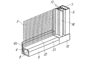
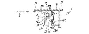
図1〜図12は、本発明に係るスクリーン張設機構の実施の一例を示している。このスクリーン張設機構は、建物開口部に設置されるサッシ1における窓等の戸障子2の内側にスクリーン3を固定的に張設するためのものであり、上記サッシ1の枠部における縦横のスクリーン取付部1A,1Bには、それぞれ、スクリーン3の取付溝7,8を設けた溝材5,6を取り付けている。この取付溝7,8は、本発明に係るスクリーン張設機構を既存のサッシに適用することを想定し、図1〜図3に示すように、上記サッシ1におけるスクリーンの取付部1A,1Bに取付溝7,8を有する溝材5,6を適数のビス9で固定することにより構成しているが、図9に示すように、上記溝材を用いることなく、サッシ1におけるスクリーン取付部1Aに直接取付溝7Aを形成し(取付部1Bの取付溝8についても同様)、あるいは、サッシに設けられている既存の溝状部を利用することもできる。
FIGS. 1-12 has shown an example of implementation of the screen extending mechanism based on this invention. This screen extending mechanism is for fixedly extending the
上記図1〜図3における縦及び横の溝材5,6は、図13及び図14に示している従来のスクリーン3の枠部材41のように、スクリーン3を張設した独立のスクリーン固定枠40として取り扱い、あるいは、操作できるものではなく、縦横の溝材5,6はその強度自体が独立した操作に耐えないものであり、また、図4に示すように、サッシ1におけるスクリーンの取付部の四隅において、それらの溝材5,6はコーナー部材10との嵌め合わせにより相互に位置合わせはしているが、相互に固定しているものではなく、サッシ1にビス9で固定している状態においては所定の枠状を保持しているが、ビス9を螺脱して溝材5,6をサッシ1から取り外した状態においては、それらは枠状を保持するものではない。なお、図4中におけるコーナー部材10の凹溝10aは、縦の取付溝7に取り付けるスクリーン3とその膨出部4(後述)の下端を嵌入させるためのものである。
The vertical and
一方、上記スクリーン3は、その四周に上記溝材5,6に対する係止用の膨出部4を付設したものとして構成している。上記膨出部4は、ファスナー半体のように可撓の布テープ4aの一側に列設した多数の係合歯により形成されたもので、上記スクリーン3の四周に汎用のファスナー(ジッパー)の半体を取り付けることにより構成することもできるが、該膨出部4はその一対が相互に噛合する必要のないものであり、そのため、ファスナー半体に近似したものにより構成することができる。
On the other hand, the
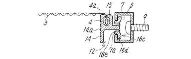
図示した実施例におけるスクリーン張設機構においては、サッシ1に取り付けた縦の溝材5におけるスクリーン3の取付溝7に対して、該スクリーン3の係止用の膨出部4を固定するに当たり、図5〜図8に示すような第1の固定手段、すなわち、上記膨出部4を係止させる係合溝15を外面側に有する溝蓋12を用いて、それに設けた係合脚16を上記取付溝7に係合させることにより固定している。上記係合溝15は溝蓋12の外面側にあるので、係合脚16等で取付溝7の溝縁等との間で挟圧されることはない。
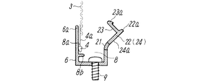
また、サッシ1に取り付けた横の溝材6におけるスクリーン3の取付溝8に対しては、図5及び図10〜12に示すような第2の固定手段、すなわち、上記膨出部4を、上記取付溝8の口縁8aと該取付溝8に施蓋する溝蓋22との間に係止させることにより行っている。この場合にも、上記取付溝8の口縁8aとの間でスクリーン3が挟圧されることはない。
In the screen extending mechanism in the illustrated embodiment, when the
Further, with respect to the
上記図5〜図8を参照して、上記第1の固定手段について更に具体的に説明すると、上記取付溝7に膨出部4を保持して取り付けられる合成樹脂製の溝蓋12は、蓋本体13として、この溝蓋12を取付溝7側に押圧するための押圧板14の背後に、上記膨出部4を係止させる係合溝15を備え、この蓋本体13に、該溝蓋12を上記スクリーン3の取付溝7に係合させるための係合脚16を備えている。上記溝蓋12に設けた押圧板14は、上記係合脚16を取付溝7に押入係止させるために、その外表面に指先押圧用の平坦押圧面14aを備えている。
The first fixing means will be described in more detail with reference to FIGS. 5 to 8. The
上記係合脚16は、取付溝7に挿入される脚板16aの先端両側に薄肉化された弾性的可撓部16bを介して一対の固定部材16cを連接することにより構成され、これらの一対の固定部材16cが、上記取付溝7に先導的に挿入可能に形成された先端部材16dと、取付溝7への該先端部材16dの挿入後に該取付溝7の口縁7aに係止することにより上記弾性的可撓部16bのまわりで姿勢を変える方向に押圧される該先端部材16dと一体の基部材16eとを有している。そして、上記固定部材16c及び上記弾性的可撓部16bは、取付溝7への上記先端部材16dの挿入後に基部材16eが該取付溝7の口縁7aに係止して弾性的可撓部16bのまわりで姿勢を変えるトグル機構を構成し、そのため、上記固定部材16cの取付溝7への装着完了後には、上記トグル機構により上記先端部材16dが上記取付溝7の口縁7aの内側に係止する状態に保持するように構成されている。
The
従って、図6に示すように、溝蓋12における係合溝15にスクリーン3の膨出部4を係止させたうえで、上記係合脚16の一対の固定部材16cにおける先端部材16dを溝材5の取付溝7の口縁7aに対向配置し、その状態で、押圧板14の平坦押圧面14aを指先で押圧することにより、図7に示すように該先端部材16dが取付溝7内へ挿入されると、該先端部材16dと基部材16eとの連結部が取付溝7の口縁7aに係止することにより、固定部材16cが上記弾性的可撓部16bの変形で上記口縁7aまわりで姿勢を変え、トグル機構により押圧板14を更に押圧しなくても、図8に示すように、上記弾性的可撓部16bが上記先端部材16dを上記取付溝7の口縁7aの内側に係止する状態に弾性的に保持するようになり、上記固定部材16cの取付溝7への装着が完了する。
なお、図9は、サッシ1の取付溝7Aに上記第1の固定手段により溝蓋12を係止させた状態を示している。
Accordingly, as shown in FIG. 6, after the bulging
FIG. 9 shows a state in which the
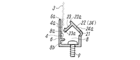
また、サッシ1に取り付けた横の溝材6におけるスクリーン3の取付溝8に上記膨出部4を固定するための第2の固定手段の構成は、図5及び図10〜12に示すように、上記サッシ1に固定した上記取付溝8を有する合成樹脂製の溝材6と、該取付溝8の口縁8aとの間に上記膨出部4を係止させる溝蓋22とを、軟質合成樹脂からなる屈曲可能な連結部21を介して合成樹脂で一体に形成し、上記膨出部4を上記取付溝8の口縁8aと該溝蓋22における上記連結部21とは反対側の蓋縁22aとの間に係合させ、該蓋縁22aの近辺に設けた係合脚23の鈎部23aを上記取付溝8の内面の係合縁8bに係合させて施蓋可能に構成している。また、上記溝蓋22は、上記係合脚23を取付溝8に押入係止させるための押圧板24を兼ねるものとして構成し、該押圧板24の表面を指先押圧用の平坦押圧面24aとしている。
Moreover, the structure of the 2nd fixing means for fixing the said bulging
従って、図10に示すように、スクリーン3の膨出部4を取付溝8における口縁8aに保持した状態で、図11に示すように溝蓋22を閉じていき、図12に示すように係合脚23の鈎部23aを取付溝8内の係合縁8bに係合させることにより、上記スクリーン3を保持させることができる。
Accordingly, as shown in FIG. 10, the
上述した実施例では、上記膨出部4の固定を、上記サッシ1における縦横のスクリーン取付部1A,1Bの一方、すなわち、縦のスクリーン取付部1Aにおいては、該膨出部4を係合溝15に係止させた溝蓋12を上記取付溝7に係合させる構成の第1の固定手段によって行い、縦横のスクリーン取付部1A,1Bの他方、すなわち、横のスクリーン取付部1Bにおいては、上記取付溝8の口縁8aと該取付溝8施蓋する溝蓋22との間に上記膨出部4を係止させて上記溝蓋22の係合脚23の鈎部23aを取付溝8の口縁8aに係止させる構成の第2の固定手段を用いている。
In the embodiment described above, the bulging
このように、縦横のスクリーン取付部1A,1Bにおいて膨出部4の固定手段を別異のものにすると、スクリーンの取付作業の手順が良好になる。すなわち、前者の溝蓋12は予め係合溝15にスクリーン3の膨出部4を挿入しておいてから溝蓋12を取付溝7に係合させるのに適しているのに対し、後者では、溝材6における取付溝8の口縁8aにスクリーンの膨出部4を保持した状態で溝蓋22を閉じることによって、スクリーン3の膨出部4の固定を行うものであり、前者の溝蓋12によるスクリーン3の一方の対向辺の取り付けを行った後、スクリーン3の他方の対向辺の取り付けを別の段階の操作として行えるので、スクリーンの取付作業が簡便化される。
Thus, if the fixing means for the bulging
しかしながら、上記スクリーン3の取付溝7,8に対するスクリーン3の四周の膨出部4の固定を、いずれも、図6〜図9に示すような、該膨出部4を係合溝15に係止させた溝蓋12を上記取付溝に係合させる第1の固定手段により行い、あるいは、いずれも、図10〜図12に示すような、上記取付溝8の口縁8aと該取付溝に施蓋する溝蓋22との間に上記膨出部4を係止させる第2の固定手段によって行うこともできる。
However, the fixing of the bulging
上記スクリーン3は、サッシ1の縦横のスクリーン取付部1A,1Bにおける取付溝7,7間及び取付溝8,8間の間隔に応じて、対向位置にある膨出部4間の間隔を設定する必要があり、上記間隔が任意のサッシに適用するためには、その対向位置にある膨出部4の少なくとも一方のスクリーン3に対する取付位置を簡易に調整可能にするとか、溝材5,6あるいは溝蓋12,22として膨出部4の取付位置を異にするものを用意するなど、適宜手段でサッシ1とスクリーン3との寸法調整を行うことができる。
The
上記実施例においては、上記取付溝7,8が上記サッシ1における内側に向けて開口するものであり、上記溝蓋12,22における押圧板14,24の平坦押圧面14a,24aが、該溝蓋12,22の係合脚16,23を上記取付溝7,8に押入できる向きに形成され、上記溝蓋12,22の係合脚16,23の上記取付溝7,8に対する係合機構、すなわち、上記第1及び第2の固定手段における係合脚16,23の取付溝7,8に対する係合が、いずれも、係合脚16,23の上記取付溝7,8に対する係合を離脱させるに要する力が、上記押圧板14,24の押圧による係合脚16,23の取付溝7,8への押入係止のための押圧力よりも大きいものとして構成している。
In the above embodiment, the mounting
このような構成は、一旦張設したスクリーンを離脱し難くするのに有効なものであるばかりでなく、スクリーンの張設操作を容易にし、熟練者でなくてもスクリーンの張設、交換等を容易に実施可能にするものである。また、上記押圧板14,24は、取付溝7,8への押入係止のための押圧力が比較的小さく、その表面を平坦押圧面14a,24aとしているので、工具等を用いることなく手作業のみで溝蓋12,22の固定を行うことを可能にするものである。
Such a configuration is effective not only for making it difficult to remove the screen once stretched, but also for facilitating the screen stretching operation, so that the screen can be stretched and replaced even by non-experts. It is easy to implement. Further, the
また、上記スクリーン3の膨出部4の第1の固定手段から導出されるスクリーン3が、上記サッシ1のスクリーン取付部1Aにおける戸障子2側に設けたスクリーン保護板11に近接配置されるように、第1の固定手段の溝蓋12における上記係合溝15を上記スクリーン保護板11に向けて開口させている。一方、上記スクリーン3の膨出部4の第2の固定手段からのスクリーン3は、上記取付溝8を有する溝材6におけるサッシ1の戸障子2側に設けたスクリーン保護板6aに沿って導出されるように、上記取付溝8に施蓋する溝蓋22の蓋縁22aが、上記スクリーン保護板6aが連設されている取付溝8の口縁8aに沿って上記膨出部を係止させるように配設されている。
このように構成すると、上記スクリーン3をサッシにおける戸障子2側に近い位置に設けられるスクリーン保護板11,6aに近接する位置に容易に配置することができ、しかも、スクリーン3の取付部分が戸障子2に近い位置において保護板11,6aにより保護されるので、スクリーンの安定的な張設に有効なものである。
Further, the
If comprised in this way, the said
上記構成を有するスクリーン張設機構を採用してスクリーン3を建物開口部のサッシ1の室内側に固定的に張設すると、該サッシ1における戸障子の開閉操作を手動で行うことが困難になる。そのため、上記スクリーン張設機構は、サッシ1の戸障子を室内側から操作できるような場合、例えば、図1〜図3に示しているような室内側でのハンドル25の操作で戸障子2を開閉できる辷り出し窓等に適している。
When the screen extending mechanism having the above configuration is employed and the
上記辷り出し窓は、図3に示すように、サッシ1の窓枠部26に両端を可回転とした一対の回転レバー27,28を介して戸障子2が回動自在に連結され、ハンドル25の回動操作で駆動される図示しないウォームを介して、ウォームホイール29を回転駆動可能とし、そのウォームホイール29に設けた凸レバー29aの先端と一方の回転レバー27の中間部分とを、駆動レバー30により回転自在に連結し、それにより、ハンドル25の回転駆動で駆動レバー30を介して一方の回転レバー27を回転駆動し、該窓枠部26から戸障子2が辷り出し状態で外側の開位置(図3)に開き、ハンドル25の逆回転操作により戸障子2が該窓枠部26を閉じる閉位置(図1)の状態にすることができるものである。
なお、ハンドル25により戸障子2を開閉する機構は極めて一般的に知られているものであるから、それらの機構を適宜採用することができる。
As shown in FIG. 3, the sliding
In addition, since the mechanism which opens and closes the
1 サッシ
1A,1B スクリーン取付部
3 スクリーン
4 膨出部
5,6 溝材
6a,11 スクリーン保護板
7,8 取付溝
7a,8a 口縁
8b 係合縁
12,22 溝蓋
14,24 押圧板
14a,24a 平坦押圧面
15 係合溝
16,23 係合脚
16a 脚板
16b 弾性的可撓部
16c 固定部材
16d 先端部材
16e 基部材
21 連結部
22a 蓋縁
23a 鈎部
DESCRIPTION OF
Claims (11)
上記サッシにおける縦横のスクリーン取付部には、スクリーンの取付溝を設け、
上記スクリーンは、その四周に係止用の膨出部を付設したものとして構成し、
上記スクリーンの取付溝に対してスクリーンの四周の係止用の膨出部を固定する固定手段は、該膨出部を係止させる係合溝を外面側に有する溝蓋、あるいは、該膨出部を上記取付溝の口縁との間に係止させる溝蓋に、それらを上記取付溝にスクリーンを挟圧することなく係合させる係合脚を設けることにより構成し、
上記溝蓋には、上記係合脚を取付溝に押入係止させるための押圧板を備え、該押圧板に指先押圧用の平坦押圧面を備えている、
ことを特徴とするスクリーン張設機構。 A screen extending mechanism for fixedly extending a screen to a sash installed in a building opening,
In the vertical and horizontal screen mounting portions in the sash, a screen mounting groove is provided,
The screen is configured as a bulging portion for locking around its four circumferences,
The fixing means for fixing the bulging portion for locking the four circumferences of the screen to the mounting groove of the screen includes a groove lid having an engaging groove for locking the bulging portion on the outer surface side, or the bulging portion A groove lid that locks the portion between the mounting groove and the edge of the mounting groove, by providing engagement legs that engage the mounting groove without pinching the screen,
The groove lid is provided with a pressing plate for pressing and locking the engaging leg into the mounting groove, and the pressing plate is provided with a flat pressing surface for fingertip pressing.
A screen extending mechanism characterized by that.
ことを特徴とする請求項1に記載のスクリーン張設機構。 The mounting groove of the screen is formed by forming a mounting groove directly on the screen mounting portion in the sash, or by fixing a groove material having the mounting groove to the sash,
The screen stretching mechanism according to claim 1.
ことを特徴とする請求項1または2に記載のスクリーン張設機構。 The mounting groove opens toward the inside of the sash, and the pressing plate in the groove lid is formed in a direction that allows the engagement leg of the groove lid to be pushed into the mounting groove. The force required to disengage the engagement of the engagement leg with respect to the attachment groove of the engagement mechanism with respect to the attachment groove is greater than the pressing force for pushing and locking the engagement leg into the attachment groove by the pressing of the pressing plate. Big one,
The screen extending mechanism according to claim 1, wherein the screen extending mechanism is provided.
ことを特徴とする請求項3に記載のスクリーン張設機構。 As the fixing means for the bulging portion on the four circumferences of the screen, the first fixing means for engaging the engaging leg of the groove lid with the bulging portion locked to the engaging groove with the mounting groove was used.
The screen extending mechanism according to claim 3.
ことを特徴とする請求項3に記載のスクリーン張設機構。 As a means for fixing the bulging portion of the four rounds of the screen, the bulging portion is locked between the lip of the mounting groove and the groove lid applied to the mounting groove, and the flange portion of the engaging leg of the groove lid is fixed. Using the second fixing means for locking to the edge of the mounting groove,
The screen extending mechanism according to claim 3.
ことを特徴とする請求項3に記載のスクリーン張設機構。 As a means for fixing the bulging portion of the screen, one of the vertical and horizontal screen mounting portions of the sash is engaged with an engaging leg of a groove lid in which the bulging portion is locked to the engaging groove. The first fixing means is used, and on the other of the vertical and horizontal screen mounting portions, the bulging portion is locked between the mouth edge of the mounting groove and the lid edge of the groove lid that covers the mounting groove. Using the second fixing means for locking the collar portion of the engagement leg of the lid to the lip of the mounting groove,
The screen extending mechanism according to claim 3.
ことを特徴とする請求項4または6に記載のスクリーン張設機構。 The groove of the first fixing means is arranged so that the screen led out from the first fixing means of the bulging portion of the screen is disposed close to the screen protection plate provided on the door sliding door side of the screen mounting portion of the sash. The engagement groove in the lid is opened toward the screen protection plate,
The screen extending mechanism according to claim 4, wherein the screen extending mechanism is provided.
ことを特徴とする請求項5または6に記載のスクリーン張設機構。 The mounting groove is provided so that the screen from the second fixing means of the bulging portion of the screen is led out along the screen protection plate provided on the door sash side of the sash in the groove member having the mounting groove. The lid edge of the lid for the groove cover is disposed so as to lock the bulging portion along the mouth edge of the mounting groove where the screen protection plate is continuously provided.
The screen extending mechanism according to claim 5 or 6, wherein the screen extending mechanism is provided.
上記一対の固定部材が、上記取付溝に先導的に挿入可能に形成された先端部材と該先端部材と一体の基部材とを有し、
上記固定部材及び上記弾性的可撓部は、取付溝への上記先端部材の挿入後に基部材が該取付溝の口縁に係止して弾性的可撓部のまわりで姿勢を変えるトグル機構を構成し、
上記固定部材の取付溝への装着完了後に、上記トグル機構により上記先端部材が上記取付溝の口縁内側に係止する状態に保持するように構成されている、
ことを特徴とする請求項4,6または7のいずれかに記載のスクリーン張設機構。 The first fixing means of the bulging portion of the screen is provided with an engaging leg for engaging with the mounting groove of the screen on a synthetic resin groove lid provided with the engaging groove, It is constituted by connecting a pair of fixing members via thin elastic flexible parts on both ends of the leg plate inserted into the mounting groove,
The pair of fixing members includes a tip member formed so as to be able to be inserted into the mounting groove in a leading manner and a base member integrated with the tip member,
The fixing member and the elastic flexible portion constitute a toggle mechanism in which the base member is engaged with the lip of the mounting groove and the posture is changed around the elastic flexible portion after the tip member is inserted into the mounting groove. ,
After the mounting of the fixing member to the mounting groove is completed, the toggle member is configured to hold the tip member in a state of being locked inside the mouth edge of the mounting groove.
The screen extending mechanism according to claim 4, wherein the screen extending mechanism is provided.
ことを特徴とする請求項5〜7のいずれかに記載のスクリーン張設機構。 The second fixing means of the bulging portion of the screen includes a groove member having the mounting groove fixed to the sash, and a groove lid for locking the bulging portion between the rim of the mounting groove. The bulging portion is formed integrally with a synthetic resin through a bendable connecting portion made of a synthetic resin, and the bulging portion is formed between a mouth edge of the mounting groove and a lid edge of the groove lid opposite to the connecting portion. Engaged between, the collar provided on the lid edge is engaged with the engagement edge of the inner surface of the mounting groove, and the lid can be applied.
The screen extending mechanism according to claim 5, wherein the screen extending mechanism is provided.
ことを特徴とする請求項1〜9のいずれかに記載のスクリーン張設機構。 The bulging portion for locking is configured by a fastener half.
The screen stretching mechanism according to any one of claims 1 to 9.
Priority Applications (1)
| Application Number | Priority Date | Filing Date | Title |
|---|---|---|---|
| JP2008239684A JP5307488B2 (en) | 2008-09-18 | 2008-09-18 | Screen extension mechanism |
Applications Claiming Priority (1)
| Application Number | Priority Date | Filing Date | Title |
|---|---|---|---|
| JP2008239684A JP5307488B2 (en) | 2008-09-18 | 2008-09-18 | Screen extension mechanism |
Publications (2)
| Publication Number | Publication Date |
|---|---|
| JP2010070977A true JP2010070977A (en) | 2010-04-02 |
| JP5307488B2 JP5307488B2 (en) | 2013-10-02 |
Family
ID=42203017
Family Applications (1)
| Application Number | Title | Priority Date | Filing Date |
|---|---|---|---|
| JP2008239684A Active JP5307488B2 (en) | 2008-09-18 | 2008-09-18 | Screen extension mechanism |
Country Status (1)
| Country | Link |
|---|---|
| JP (1) | JP5307488B2 (en) |
Cited By (7)
| Publication number | Priority date | Publication date | Assignee | Title |
|---|---|---|---|---|
| JP2012197579A (en) * | 2011-03-18 | 2012-10-18 | Seiki Juko Kk | Assembly screen door and assembly method of the same |
| JP2015113566A (en) * | 2013-12-09 | 2015-06-22 | セイキ販売株式会社 | Screen device |
| JP2015197027A (en) * | 2014-04-03 | 2015-11-09 | 林口工業株式会社 | Wire screen device |
| JP2018080446A (en) * | 2016-11-14 | 2018-05-24 | アルメタックス株式会社 | Screen mounting device for sash window |
| JP2018111924A (en) * | 2017-01-06 | 2018-07-19 | セイキ販売株式会社 | Screen device |
| JP2019148107A (en) * | 2018-02-27 | 2019-09-05 | 株式会社Lixil | Net window and fitting with net window |
| JP2020084567A (en) * | 2018-11-26 | 2020-06-04 | セイキ住工株式会社 | Horizontally sliding storable screen device |
Citations (4)
| Publication number | Priority date | Publication date | Assignee | Title |
|---|---|---|---|---|
| JPS52161940U (en) * | 1976-06-01 | 1977-12-08 | ||
| JPH076508U (en) * | 1993-06-30 | 1995-01-31 | 日本軽金属株式会社 | Seat tension device |
| JP2007177566A (en) * | 2005-12-28 | 2007-07-12 | Shin Nikkei Co Ltd | Sashed window screen and its mounting structure |
| JP2008050805A (en) * | 2006-08-23 | 2008-03-06 | Tostem Corp | Opening section device with netting member |
-
2008
- 2008-09-18 JP JP2008239684A patent/JP5307488B2/en active Active
Patent Citations (4)
| Publication number | Priority date | Publication date | Assignee | Title |
|---|---|---|---|---|
| JPS52161940U (en) * | 1976-06-01 | 1977-12-08 | ||
| JPH076508U (en) * | 1993-06-30 | 1995-01-31 | 日本軽金属株式会社 | Seat tension device |
| JP2007177566A (en) * | 2005-12-28 | 2007-07-12 | Shin Nikkei Co Ltd | Sashed window screen and its mounting structure |
| JP2008050805A (en) * | 2006-08-23 | 2008-03-06 | Tostem Corp | Opening section device with netting member |
Cited By (8)
| Publication number | Priority date | Publication date | Assignee | Title |
|---|---|---|---|---|
| JP2012197579A (en) * | 2011-03-18 | 2012-10-18 | Seiki Juko Kk | Assembly screen door and assembly method of the same |
| JP2015113566A (en) * | 2013-12-09 | 2015-06-22 | セイキ販売株式会社 | Screen device |
| JP2015197027A (en) * | 2014-04-03 | 2015-11-09 | 林口工業株式会社 | Wire screen device |
| JP2018080446A (en) * | 2016-11-14 | 2018-05-24 | アルメタックス株式会社 | Screen mounting device for sash window |
| JP2018111924A (en) * | 2017-01-06 | 2018-07-19 | セイキ販売株式会社 | Screen device |
| JP2019148107A (en) * | 2018-02-27 | 2019-09-05 | 株式会社Lixil | Net window and fitting with net window |
| JP2020084567A (en) * | 2018-11-26 | 2020-06-04 | セイキ住工株式会社 | Horizontally sliding storable screen device |
| JP7072227B2 (en) | 2018-11-26 | 2022-05-20 | セイキ住工株式会社 | Horizontally retractable screen device |
Also Published As
| Publication number | Publication date |
|---|---|
| JP5307488B2 (en) | 2013-10-02 |
Similar Documents
| Publication | Publication Date | Title |
|---|---|---|
| JP5307488B2 (en) | Screen extension mechanism | |
| KR100714975B1 (en) | click-on stretch covering apparatus for lamp | |
| JP4875953B2 (en) | Opening device provided with opening and closing means | |
| KR101631707B1 (en) | Driving unit of system louver and system louver device using the same | |
| JP5754918B2 (en) | Screen door and sash | |
| JP6491500B2 (en) | Screen door | |
| JP6031135B2 (en) | Screen door and sash | |
| JP2016142055A (en) | Net window and sash | |
| JP6114688B2 (en) | Screen device | |
| KR101631708B1 (en) | Driving unit of system louver and system louver device using the same | |
| KR200453991Y1 (en) | Turning push-button type lock assembly for window | |
| JP5145268B2 (en) | Guide frame mounting mechanism in screen device | |
| US5230376A (en) | Door with transom window | |
| JP2007016383A (en) | Heat insulating screen | |
| JPH11200731A (en) | Fixture for airtight material in window | |
| JP4155907B2 (en) | Screen installation mechanism for sash frame | |
| JP7337227B2 (en) | Fittings | |
| JP3155096U (en) | Building skylight | |
| JP2010159551A (en) | Device for stretching screen on sash framework body | |
| CN201225078Y (en) | Blind door capable of opening and closing | |
| JP6364058B2 (en) | Sash window screen installation equipment | |
| JPH0211581Y2 (en) | ||
| JP3386118B2 (en) | Window ventilation lock | |
| KR200259275Y1 (en) | A locking device for a window frame | |
| JP2558689Y2 (en) | Folding screen |
Legal Events
| Date | Code | Title | Description |
|---|---|---|---|
| A621 | Written request for application examination |
Free format text: JAPANESE INTERMEDIATE CODE: A621 Effective date: 20100805 |
|
| A977 | Report on retrieval |
Free format text: JAPANESE INTERMEDIATE CODE: A971007 Effective date: 20111014 |
|
| A131 | Notification of reasons for refusal |
Free format text: JAPANESE INTERMEDIATE CODE: A131 Effective date: 20111025 |
|
| A521 | Request for written amendment filed |
Free format text: JAPANESE INTERMEDIATE CODE: A523 Effective date: 20111226 |
|
| A131 | Notification of reasons for refusal |
Free format text: JAPANESE INTERMEDIATE CODE: A131 Effective date: 20120710 |
|
| A521 | Request for written amendment filed |
Free format text: JAPANESE INTERMEDIATE CODE: A523 Effective date: 20120903 |
|
| TRDD | Decision of grant or rejection written | ||
| A01 | Written decision to grant a patent or to grant a registration (utility model) |
Free format text: JAPANESE INTERMEDIATE CODE: A01 Effective date: 20130604 |
|
| A61 | First payment of annual fees (during grant procedure) |
Free format text: JAPANESE INTERMEDIATE CODE: A61 Effective date: 20130627 |
|
| R150 | Certificate of patent or registration of utility model |
Free format text: JAPANESE INTERMEDIATE CODE: R150 Ref document number: 5307488 Country of ref document: JP Free format text: JAPANESE INTERMEDIATE CODE: R150 |
|
| R250 | Receipt of annual fees |
Free format text: JAPANESE INTERMEDIATE CODE: R250 |
|
| R250 | Receipt of annual fees |
Free format text: JAPANESE INTERMEDIATE CODE: R250 |
|
| R250 | Receipt of annual fees |
Free format text: JAPANESE INTERMEDIATE CODE: R250 |
|
| R250 | Receipt of annual fees |
Free format text: JAPANESE INTERMEDIATE CODE: R250 |