JP2010069485A - Positioning tool - Google Patents
Positioning tool Download PDFInfo
- Publication number
- JP2010069485A JP2010069485A JP2008236500A JP2008236500A JP2010069485A JP 2010069485 A JP2010069485 A JP 2010069485A JP 2008236500 A JP2008236500 A JP 2008236500A JP 2008236500 A JP2008236500 A JP 2008236500A JP 2010069485 A JP2010069485 A JP 2010069485A
- Authority
- JP
- Japan
- Prior art keywords
- clamp
- positioning jig
- plate
- shaped steel
- mounting
- Prior art date
- Legal status (The legal status is an assumption and is not a legal conclusion. Google has not performed a legal analysis and makes no representation as to the accuracy of the status listed.)
- Granted
Links
Images


Abstract
Description
本発明は、H型鋼のフランジ,ウェブの間に差込まれ溶接により固定される板形の補助鋼材の取付け位置を案内する位置決め用治具に係る技術分野に属する。 The present invention belongs to a technical field related to a positioning jig for guiding a mounting position of a plate-shaped auxiliary steel material that is inserted between a flange and a web of an H-shaped steel and fixed by welding.
最近、H型鋼に対する補助鋼材の溶接による固定作業を効率化するため、補助鋼材の取付け位置を案内する位置決め用治具が使用されるようになってきている。この位置決め用治具は、H型鋼の一部に装着されて補助鋼材を支持する構造を備え、補助鋼材の取付け位置を規定する定規を用いた罫書き作業を省略または簡略化するとともに、溶接の際の補助鋼材の位置ずれを防止するものである。従って、位置決め用治具については、補助鋼材の取付け位置の案内が精密,確実であることが要求される。 Recently, a positioning jig for guiding the mounting position of the auxiliary steel material has been used in order to improve the efficiency of the fixing work by welding the auxiliary steel material to the H-shaped steel. This positioning jig has a structure that is attached to a part of the H-shaped steel and supports the auxiliary steel material, omits or simplifies the scoring work using a ruler that defines the mounting position of the auxiliary steel material, This prevents misalignment of the auxiliary steel material. Therefore, the positioning jig is required to be precise and reliable in guiding the mounting position of the auxiliary steel material.
従来、補助鋼材の取付け位置の案内を精密化,確実化することを指向した位置決め用治具としては、例えば、下記特許文献1に記載のものが知られている。
特許文献1には、回動構造,スライド構造で連結されH型鋼のフランジに当接される複数の装着用フレームと、装着用フレームに回動可能に取付けられ補助鋼材を支持する支持板とを備えた位置決め用治具が記載されている。
2. Description of the Related Art Conventionally, as a positioning jig oriented to refine and ensure the guidance of the mounting position of an auxiliary steel material, for example, the one described in
特許文献1に係る位置決め用治具は、装着用フレーム,支持板の回動,スライドによって補助鋼材の取付け位置を調整して精密に案内するとともに、支持板を複数の装着用フレームで支持することによって補助鋼材の位置ずれを防止して取付け位置を確実に案内するものである。
特許文献1に係る位置決め用治具では、複数の装着用フレームを回動操作,スライド操作してH型鋼に装着しなければならないため、H型鋼への装着操作が面倒であるという問題点がある。また、装着用フレームが回動構造,スライド構造で連結されて構造が複雑であるため、製造コストが高くなるという問題点がある。
The positioning jig according to
本発明は、このような問題点を考慮してなされたもので、H型鋼への装着操作が容易で安価に製造することのできる位置決め用治具を提供することを課題とする。 The present invention has been made in consideration of such problems, and an object of the present invention is to provide a positioning jig that is easy to mount on an H-shaped steel and can be manufactured at low cost.
前述の課題を解決するため、本発明に係る位置決め用治具は、特許請求の範囲の各請求項に記載の手段を採用する。 In order to solve the above-described problems, the positioning jig according to the present invention employs means described in each of the claims.
即ち、請求項1では、H型鋼のフランジに装着される装着部と、H型鋼のフランジ,ウェブの間に差込まれ溶接により固定される板形の補助鋼材を支持する支持部とからなる位置決め用治具において、装着部は手動で操作され挟付け状態をロックする機能を有する鋏形のクランプとクランプの一方のクランプ片が外側面に支持され内側面がH型鋼のフランジの外側面に当接されるベース板とを備え、支持部は装着部のベース板に固定されていることを特徴とする。
In other words, in
この手段では、装着部のクランプでH型鋼のフランジを挟付けることで、ベース板をH型鋼のフランジ部の外側面に当接させワンタッチ操作でH型鋼への装着を完了することができる。また、装着部のクランプ以外に回動,スライド等の動作機構を備えないことで、構造が簡素化されている。 With this means, the H-shaped steel flange is clamped by the clamp of the mounting portion, so that the base plate can be brought into contact with the outer surface of the flange portion of the H-shaped steel and the mounting on the H-shaped steel can be completed by a one-touch operation. Moreover, the structure is simplified by not providing an operation mechanism such as rotation and slide other than the clamp of the mounting portion.
また、請求項2では、請求項1の位置決め用治具において、装着部はベース板の内側面に突出されて直線上に配置され端面がH型鋼のフランジの外側面に当接可能で周面がH型鋼のフランジの端面に当接可能な複数個のガイドピンを備えていることを特徴とする。 According to a second aspect of the present invention, in the positioning jig of the first aspect, the mounting portion protrudes from the inner surface of the base plate and is arranged on a straight line, and the end surface can contact the outer surface of the H-shaped steel flange. Is provided with a plurality of guide pins capable of coming into contact with the end face of the flange of the H-shaped steel.
この手段では、装着部にガイドピンが備えられることで、ベース板とともにH型鋼のフランジへの装着に精度が確保される。 In this means, the mounting portion is provided with the guide pin, so that the accuracy is ensured in mounting to the flange of the H-shaped steel together with the base plate.
また、請求項3では、請求項1または2の位置決め用治具において、装着部はクランプがベース板に回動可能に支持されていることを特徴とする。 According to a third aspect of the present invention, in the positioning jig according to the first or second aspect, the mounting portion is supported by the base plate so that the clamp is rotatable.
この手段では、装着部のクランプがベース板に回動可能に支持されることで、クランプのH型鋼のフランジへの挟付け面積を増大するように調整することができる。 With this means, the clamp of the mounting portion is rotatably supported by the base plate, so that the clamping area of the clamp to the H-shaped steel flange can be adjusted to be increased.
また、請求項4では、請求項1〜3のいずれかの位置決め用治具において、支持部は装着部のベース板に固定された連結板と連結板に階層状に取付けられて補助鋼材に当接される複数枚の支持板とを備えていることを特徴とする。 According to a fourth aspect of the present invention, in the positioning jig according to any one of the first to third aspects, the support portion is attached to the base plate of the mounting portion and the connection plate in a layered manner so as to contact the auxiliary steel material. And a plurality of supporting plates in contact with each other.
この手段では、支持部として補助鋼材に当接される複数枚の支持板が階層状に設けられることで、補助鋼材が複数箇所で支持されることになる。 In this means, a plurality of support plates that are in contact with the auxiliary steel material as support portions are provided in a layered manner, so that the auxiliary steel material is supported at a plurality of locations.
また、請求項5では、請求項4の位置決め用治具において、支持部は支持板の間隔が不規則的に設定されていることを特徴とする。 According to a fifth aspect of the present invention, in the positioning jig according to the fourth aspect of the present invention, the intervals between the support plates of the support portion are set irregularly.
この手段では、支持部の支持板の間隔が不規則的に設定されていることで、大きさ(H型鋼のフランジの間隔)の異なるH型鋼,補助鋼材への対応が可能になる。 In this means, since the intervals between the support plates of the support portion are set irregularly, it is possible to cope with H-shaped steel and auxiliary steel materials having different sizes (intervals of the flanges of the H-shaped steel).
また、請求項6では、請求項4の位置決め用治具において、支持部は支持板が連結板に対する取付け位置を変更可能であることを特徴とする。 According to a sixth aspect of the present invention, in the positioning jig according to the fourth aspect of the present invention, the support portion can change the mounting position of the support plate relative to the connecting plate.
この手段では、支持部の支持板の連結板に対する取付け位置を変更することで、大きさの異なるH型鋼,補助鋼材への対応が可能になる。 With this means, it is possible to cope with H-shaped steel and auxiliary steel materials having different sizes by changing the mounting position of the support portion of the support plate relative to the connecting plate.
本発明に係る位置決め用治具は、装着部のクランプでH型鋼のフランジを挟付けることで、ベース板をH型鋼のフランジ部の外側面に当接させワンタッチ操作でH型鋼への装着を完了することができるため、H型鋼への装着操作が容易となる効果がある。また、装着部のクランプ以外に回動,スライド等の動作機構を備えないことで、構造が簡素化されているため、安価に製造することができる効果がある。 With the positioning jig according to the present invention, the base plate is brought into contact with the outer surface of the flange portion of the H-shaped steel by clamping the H-shaped steel flange with the clamp of the mounting portion, and the mounting to the H-shaped steel is completed by one-touch operation. Therefore, there is an effect that the mounting operation to the H-shaped steel becomes easy. Moreover, since the structure is simplified by not providing an operation mechanism such as rotation and slide in addition to the clamp of the mounting portion, there is an effect that it can be manufactured at low cost.
さらに、請求項2として、装着部にガイドピンが備えられることで、ベース板とともにH型鋼のフランジへの装着に精度が確保されるため、補助鋼材の取付け位置の案内を精密化することができる効果がある。
Further, as claimed in
さらに、請求項3として、装着部のクランプがベース板に回動可能に支持されることで、クランプのH型鋼のフランジへの挟付け面積を増大するように調整することができるため、クランプによるH型鋼のフランジの挟付け力を強力に保持して、補助鋼材の取付け位置の案内を確実化することができる効果がある。 Further, as claimed in claim 3, since the clamp of the mounting portion is rotatably supported by the base plate, it can be adjusted to increase the clamping area of the clamp to the flange of the H-shaped steel. There is an effect that the holding force of the flange of the H-shaped steel is strongly held and the guide of the attachment position of the auxiliary steel material can be ensured.
さらに、請求項4として、支持部として補助鋼材に当接される複数枚の支持板が階層状に設けられることで、補助鋼材が複数箇所で支持されることになるため、補助鋼材の取付け位置の案内を精密化,確実化することができる効果がある。 Further, as claimed in claim 4, since the support steel is supported in a plurality of places by providing a plurality of support plates in contact with the auxiliary steel as a support portion, the mounting position of the auxiliary steel is provided. There is an effect that the guidance of can be refined and ensured.
さらに、請求項5として、支持部の支持板の間隔が不規則的に設定されていることで、大きさ(H型鋼のフランジの間隔)の異なるH型鋼,補助鋼材への対応が可能になるため、汎用性が高くなる効果がある。 Further, as claimed in claim 5, since the intervals between the support plates of the support portion are set irregularly, it is possible to cope with H-type steel and auxiliary steel materials having different sizes (intervals of H-type steel flanges). Therefore, there is an effect that versatility is enhanced.
さらに、請求項6として、支持部の支持板の連結板に対する取付け位置を変更することで、大きさの異なるH型鋼,補助鋼材への対応が可能になるため、汎用性が高くなる効果がある。 Furthermore, as claimed in claim 6, by changing the attachment position of the support plate with respect to the connecting plate of the support portion, it becomes possible to cope with H-shaped steel and auxiliary steel materials having different sizes. .
以下、本発明に係る位置決め用治具を実施するための最良の形態を図面に基づいて説明する。 Hereinafter, the best mode for carrying out a positioning jig according to the present invention will be described with reference to the drawings.
図1〜図8は、本発明に係る位置決め用治具を実施するための最良の形態の第1例を示すものである。 1 to 8 show a first example of the best mode for carrying out the positioning jig according to the present invention.
第1例では、比較的小型に構成されるものを示してある。 In the first example, a relatively small size is shown.
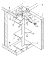
第1例は、図1,図2に示すように、H型鋼WのフランジWaに装着される装着部1と、H型鋼WのフランジWa,ウェブWbの間に差込まれ溶接により固定される板形の補助鋼材Pを支持する支持部2とで構成されている。
As shown in FIGS. 1 and 2, the first example is inserted between the
装着部1は、クランプ11,ベース板12,取付軸13,ガイドピン14を備えている。
The
装着部1のクランプ11は、図3に詳細に示されるように、先端部の挟付け動作部となる両クランプ片(挟片)11a,11bに固定側把手11c,第1の可動側把手11dがそれぞれ連結されて手動で操作される鋏形に形成されている。一方のクランプ片11aと固定側把手11cとは、一体化されるように連結されている。他方のクランプ片11bと固定側把手11cとは、第1の支軸11eで回動可能に連結されている。他方のクランプ片11bと第1の可動側把手11dとは、第2の支軸11fで回動可能に連結されている。他方のクランプ片11bは、H型鋼Wの厚さのあるフランジWaに対応してクランプ回動域を拡大できるように湾曲形に形成されている。第1の可動側把手11dの中途部には、第3の支軸11gで第2の可動側把手11hが回動可能に連結されている。第1の可動側把手11dの第2の支軸11f寄りには、第4の支軸11iでリンクアーム11jが回動可能に連結されている。リンクアーム11jは、中途部がリンクアーム11jに係止され、端部が固定側把手11cに支持されて固定側把手11c,第1の可動側把手11dの開度(両クランプ片11a,11bの開度でもある)を調整する開度調整機構11kに係止されている。開度調整機構11kは、調整ネジ11kaと調整ネジ11kaの回動で進退するネジ棒11kbとからなる。リンクアーム11jの端部は、開度調整機構11kのネジ棒11kbの端面に突当てられている。さらに、他方のクランプ片11bと固定側把手11cとの間には、両者を引張方向に弾圧付勢されたコイルスプリング11lが掛渡されている。
As shown in detail in FIG. 3, the
この装着部1のクランプ11は、固定側把手11cに対して第1の可動側把手11d,第2の可動側把手11hを一体的に回動させることで、両クランプ片11a,11bの挟付け状態,開放状態をロックすることができるという機能を有している。
The
装着部1のベース板12は、金属板で方形に形成されてなるもので、外側面12a,内側面12bが平坦な仕上げになっている。
The
装着部1の取付軸13は、クランプ11の一方のクランプ片11aに貫通されてベース板12の一方の長手辺近くに外側面12aから固定されている。従って、クランプ11の一方のクランプ片11aは、ベース板12の外側面12aに当接されている。この結果、クランプ11の他方のクランプ11bは、ベース板12の内側面12bに対面されることになる。なお、クランプ11は、取付軸13を中心として回動が可能である。
The mounting
装着部1のガイドピン14は、金属材で円柱形に形成されたベース板12の一方の長手辺近くに外側面12aから内側面12bを貫通するピン本体14aと、ベース板12の外側面12aに固定されピン本体14aの端部がスライド可能に収容されたスリーブ14bと、ピン本体14a,スリーブ14bとの間に設けられピン本体14aをベース板12の内側面12b方向へ弾圧するスプリング14cとからなる。このガイドピン14は、装着部1の取付軸13を介して相対するように2個がベース板12の一方の長手辺と平行な直線上に配置されている。
The
支持部2は、連結板21,支持板22を備えている。
The
支持部2の連結板21は、金属材で細長板形に形成されてなるもので、一方の短手辺が装着部1のベース板12の一方の長手辺の縁に当接されて固定され、装着部1のベース板12とL字形を形成する格好となっている。連結板21の装着部1のベース板12寄りには、装着部1のクランプ11の他方のクランプ片11bが進入する窓21aが開口されている。
The connecting
支持部2の支持板22は、金属板で異形の方形に形成されてなるもので、連結板21の長さ方向と直交するように、3枚が階層状に連結板21に固定されている。この支持板22は、長手辺に連結板21を避ける切欠部22aを有して短手辺側に連結板21を超えて少しの幅aで突出した突出部22bが設けられている。なお、3枚の連結板21の間隔b,c,d,eは、それぞれ相違している(図3参照)。
The
第1例によると、装着部1について、特許文献1に係る位置決め用治具のような回動構造,スライド構造で複数の装着フレームを連結する構成が採用されていない。従って、特許文献1に係る位置決め用治具に比して構造が簡素化されているため、安価に製造することが可能になる。
According to the first example, the mounting
第1例を使用するには、図1に示すように、装着部1のクランプ11の固定側把手11cと第1の可動側把手11d,第2の可動側把手11hとを開き両クランプ片11a,11bを開放状態(ロックされている)としておく。そして、装着部1のベース板12の内側面12bをH型鋼Wの上側のフランジWaの外側面に当接させてスライドさせ、装着部1のクランプ11の両クランプ片11a,11bの間にH型鋼Wの上側のフランジWaに位置させる。このとき、装着部1のガイドピン14のスプリング14cの弾圧によってスリーブ14bから突出しているピン本体14aがH型鋼Wの上側のフランジWaの端面に突当たることで、装着部1のベース板12のスライドが停止される。
In order to use the first example, as shown in FIG. 1, the fixed
この後、図2,図3に示すように、装着部1のクランプ11の固定側把手11cと第1の可動側把手11d,第2の可動側把手11hとを閉め両クランプ片11a,11bを挟付け状態とする。この結果、装着部1のクランプ11がH型鋼Wの上側のフランジWaに挟付けられてロックされることになる。
Thereafter, as shown in FIGS. 2 and 3, the fixed
従って、ワンタッチ操作でH型鋼Wへの装着を完了することができるため、H型鋼Wへの装着操作が容易となる。 Accordingly, since the mounting on the H-shaped steel W can be completed by a one-touch operation, the mounting operation on the H-shaped steel W is facilitated.
H型鋼Wへ装着された状態では、装着部1のベース板12の内側面12bとH型鋼Wの上側のフランジWaの外側面とによって上下方向の位置が規制され(図3参照)、装着部1のガイドピン14のピン本体14aとH型鋼Wの上側のフランジWaの端面とによって上下方向と直交する水平方向の位置が規制される(図4,図5参照)。これ等の位置の規制は、装着部1のベース板12の内側面12bと装着部1のガイドピン14のピン本体14aとの平坦な仕上げによって高い精度が確保される。従って、装着部1,支持部2の組付け精度や支持部2の支持板22の方形の精度を確保すれば、支持部2の支持板22の短手辺に板形の補助鋼材Pを当接させることで、補助鋼材Pの取付け位置(H型鋼WのフランジWa,ウェブWbに対してそれぞれ90度の角度)を精密に案内することができる。そして、全体が装着部1のクランプ11によってH型鋼Wの上側のフランジWaに強固に装着され、溶接作業等の際にずれが生ずるおそれがないため、補助鋼材Pの取付け位置を確実に案内することができる。
When mounted on the H-shaped steel W, the vertical position is regulated by the
なお、支持部2の支持板22の突出部22bは、補助鋼材Pの取付け位置の案内長を増長してより精密な案内を可能にする。また、支持部2の支持板22の間隔b,c,d,eの相違は、フランジWaの間隔の異なる各種のH型鋼Wへの対応を可能にして汎用性を高めることになる。
In addition, the
さらに、第1例では、図6〜図8に示すように、装着部1のベース板12の内側面12bのH型鋼Wの上側のフランジWaの外側面への当接させたスライド方向を変更することで、補助鋼材Pの取付け位置を変更(H型鋼WのウェブWbに対して90度の以外の角度)することができる。このとき、H型鋼Wの上側のフランジWaの外側面へ当接されたガイドピン14は、図7に示すように、ピン本体14aがスプリング14cの弾圧に抗してスリーブ14bに後退する。従って、装着部1のベース板12の内側面12bのH型鋼Wの上側のフランジWaの外側面への当接が確保される。また、図8に示すように、クランプ11を取付軸13を中心として回動させることで、溶接作業の邪魔にならずしかも適当は締付力が確保されるクランプ11の角度を調整することができる。
Furthermore, in the first example, as shown in FIGS. 6 to 8, the sliding direction in which the
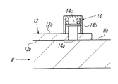
図9は、本発明に係る位置決め用治具を実施するための最良の形態の第2例を示すものである。 FIG. 9 shows a second example of the best mode for carrying out the positioning jig according to the present invention.
第2例は、支持部2の連結板21に長軸が長さ方向へ延びた長孔21bが開口され、支持板22に取付けられボルト23が連結板21の長孔21bに挿通されナット24で連結板21に固定されるようになっている。
In the second example, a
第2例によると、支持部2の連結板21に対する支持板22の配置が可変されるため、支持板22の枚数を少なくして構造をより簡素化しても、フランジWaの間隔の異なる各種のH型鋼Wへの対応が損なわれなくなる。
According to the second example, since the arrangement of the
図10は、本発明に係る位置決め用治具を実施するための最良の形態の第3例を示すものである。 FIG. 10 shows a third example of the best mode for carrying out the positioning jig according to the present invention.
第3例は、第2例について、支持部2の連結板21の長孔21bが省略され、支持部2の連結板21の両端面(木口面)の長さ方向に一定間隔で支持板22が差込まれる差込溝21cが設けられ、差込溝21cに対応して第2例の長孔21bがあった位置に一定間隔でボルト23が挿通されるボルト孔21dが設けられている。
In the third example, the
第3例によると、第2例と同様の作用,効果が奏されることに加えて、支持部2の連結板21,支持板22の組付け強度が強化される作用,効果が得られる。
According to the third example, in addition to the same operations and effects as those of the second example, the operations and effects of strengthening the assembly strength of the
以上、図示した各例の外に、装着部1のクランプ11を他の構造のものとすることもできる。また、装着部1のクランプ11を複数個備えて大型化させることも可能である。
As described above, in addition to the illustrated examples, the
さらに、装着部1のクランプ11で強固に装着されるため、H型鋼Wの配設について上下,左右,傾斜のいずれについても対応することが可能である。
Furthermore, since it is firmly attached by the
1 装着部
11 クランプ
12 ベース板
14 ガイドピン
2 支持部
21 連結板
22 支持板
P 補助鋼材
W H型鋼
Wa フランジ
Wb ウェブ
DESCRIPTION OF
Claims (6)
Priority Applications (1)
| Application Number | Priority Date | Filing Date | Title |
|---|---|---|---|
| JP2008236500A JP4648969B2 (en) | 2008-09-16 | 2008-09-16 | Positioning jig |
Applications Claiming Priority (1)
| Application Number | Priority Date | Filing Date | Title |
|---|---|---|---|
| JP2008236500A JP4648969B2 (en) | 2008-09-16 | 2008-09-16 | Positioning jig |
Publications (2)
| Publication Number | Publication Date |
|---|---|
| JP2010069485A true JP2010069485A (en) | 2010-04-02 |
| JP4648969B2 JP4648969B2 (en) | 2011-03-09 |
Family
ID=42201755
Family Applications (1)
| Application Number | Title | Priority Date | Filing Date |
|---|---|---|---|
| JP2008236500A Expired - Fee Related JP4648969B2 (en) | 2008-09-16 | 2008-09-16 | Positioning jig |
Country Status (1)
| Country | Link |
|---|---|
| JP (1) | JP4648969B2 (en) |
Cited By (5)
| Publication number | Priority date | Publication date | Assignee | Title |
|---|---|---|---|---|
| CN104084732A (en) * | 2014-06-18 | 2014-10-08 | 浙江吉利控股集团有限公司 | Manual mounting tool for middle-row seat right lock catch mounting plate |
| CN104889638A (en) * | 2014-03-04 | 2015-09-09 | 南昌欧菲光电技术有限公司 | Auxiliary welding device |
| CN106903474A (en) * | 2017-03-29 | 2017-06-30 | 广州铁路职业技术学院 | The clamp assemblies of welding tooling |
| CN109531224A (en) * | 2018-12-10 | 2019-03-29 | 上海烨恒木业机械有限公司 | A kind of numerical control of machine tools multi-angle positioning gear ruler |
| CN117139977B (en) * | 2023-10-27 | 2024-02-06 | 中国建筑第五工程局有限公司 | Auxiliary welding equipment for building embedded parts |
Citations (7)
| Publication number | Priority date | Publication date | Assignee | Title |
|---|---|---|---|---|
| JPS5989696U (en) * | 1982-12-03 | 1984-06-18 | 畠中 信義 | Steel positioning jig |
| JPS59148190U (en) * | 1983-03-25 | 1984-10-03 | 畠中 信義 | Horizontal positioning jig for steel materials |
| JPS6192566U (en) * | 1984-11-22 | 1986-06-16 | ||
| JPS63207567A (en) * | 1987-02-25 | 1988-08-26 | ピーターセン マニュファクチュアリングカンパニー インコーポレーテッド | Hand tool for gripping |
| JPH01114192U (en) * | 1988-01-22 | 1989-08-01 | ||
| JP2002307317A (en) * | 2001-04-11 | 2002-10-23 | Funai Electric Co Ltd | Tip rotation type cutting pliers |
| JP2003211290A (en) * | 2002-01-18 | 2003-07-29 | Yajima:Kk | Auxiliary tool for welding |
-
2008
- 2008-09-16 JP JP2008236500A patent/JP4648969B2/en not_active Expired - Fee Related
Patent Citations (7)
| Publication number | Priority date | Publication date | Assignee | Title |
|---|---|---|---|---|
| JPS5989696U (en) * | 1982-12-03 | 1984-06-18 | 畠中 信義 | Steel positioning jig |
| JPS59148190U (en) * | 1983-03-25 | 1984-10-03 | 畠中 信義 | Horizontal positioning jig for steel materials |
| JPS6192566U (en) * | 1984-11-22 | 1986-06-16 | ||
| JPS63207567A (en) * | 1987-02-25 | 1988-08-26 | ピーターセン マニュファクチュアリングカンパニー インコーポレーテッド | Hand tool for gripping |
| JPH01114192U (en) * | 1988-01-22 | 1989-08-01 | ||
| JP2002307317A (en) * | 2001-04-11 | 2002-10-23 | Funai Electric Co Ltd | Tip rotation type cutting pliers |
| JP2003211290A (en) * | 2002-01-18 | 2003-07-29 | Yajima:Kk | Auxiliary tool for welding |
Cited By (6)
| Publication number | Priority date | Publication date | Assignee | Title |
|---|---|---|---|---|
| CN104889638A (en) * | 2014-03-04 | 2015-09-09 | 南昌欧菲光电技术有限公司 | Auxiliary welding device |
| CN104084732A (en) * | 2014-06-18 | 2014-10-08 | 浙江吉利控股集团有限公司 | Manual mounting tool for middle-row seat right lock catch mounting plate |
| CN106903474A (en) * | 2017-03-29 | 2017-06-30 | 广州铁路职业技术学院 | The clamp assemblies of welding tooling |
| CN109531224A (en) * | 2018-12-10 | 2019-03-29 | 上海烨恒木业机械有限公司 | A kind of numerical control of machine tools multi-angle positioning gear ruler |
| CN109531224B (en) * | 2018-12-10 | 2024-04-05 | 上海烨恒木业机械有限公司 | Numerical control multi-angle positioning blocking ruler for machine tool |
| CN117139977B (en) * | 2023-10-27 | 2024-02-06 | 中国建筑第五工程局有限公司 | Auxiliary welding equipment for building embedded parts |
Also Published As
| Publication number | Publication date |
|---|---|
| JP4648969B2 (en) | 2011-03-09 |
Similar Documents
| Publication | Publication Date | Title |
|---|---|---|
| JP4648969B2 (en) | Positioning jig | |
| KR100823158B1 (en) | Tacking jig of pipe and flange, and tacking method there of | |
| US20130221594A1 (en) | Clamping mechanism | |
| JP5258069B2 (en) | Multipurpose chamfering machine {MultipurposeBeveler} | |
| US8651777B2 (en) | Adjustable doweling jig | |
| JP2021506627A (en) | Additional support equipment for geographic features | |
| RU2484948C2 (en) | Jig for circular cutoff saw for oblique cutting and circular cutoff saw for oblique cutting | |
| KR101944995B1 (en) | Circular Saw Machine | |
| CN210147284U (en) | Laser cutting clamp | |
| US11219984B2 (en) | Clamp with workpiece alignment feature | |
| KR20060128343A (en) | Pipe bending machine | |
| JP2008290238A (en) | Right-angled positioning device, locking plier, and f clamp | |
| CN113441898A (en) | Template anchor clamps, template tool and welding equipment | |
| WO2010050312A1 (en) | Ruler for tool | |
| CN214025430U (en) | Steel arch connecting plate positioning device | |
| CN211661358U (en) | Adjusting device | |
| CN210849274U (en) | Drilling clamp for machining industry | |
| US20080203642A1 (en) | Apparatus and method for positioning a workpiece in a working orientation | |
| JP2810653B2 (en) | Cutting and bending angle free cutting machine | |
| JP2010269430A (en) | Ruler for tool | |
| CN217095841U (en) | Numerical control multi-hole-site drilling machine mechanism | |
| JP3051874U (en) | Cutting width ruler for electric circular saw tool | |
| US20230294218A1 (en) | Torch support and guide apparatus, method of using same, and kit for constructing same | |
| JP3205922U (en) | Grooving jig | |
| GB2058613A (en) | Boring tool guide |
Legal Events
| Date | Code | Title | Description |
|---|---|---|---|
| A131 | Notification of reasons for refusal |
Free format text: JAPANESE INTERMEDIATE CODE: A131 Effective date: 20100112 |
|
| A521 | Written amendment |
Free format text: JAPANESE INTERMEDIATE CODE: A523 Effective date: 20100216 |
|
| A131 | Notification of reasons for refusal |
Free format text: JAPANESE INTERMEDIATE CODE: A131 Effective date: 20100413 |
|
| A521 | Written amendment |
Free format text: JAPANESE INTERMEDIATE CODE: A523 Effective date: 20100603 |
|
| A131 | Notification of reasons for refusal |
Free format text: JAPANESE INTERMEDIATE CODE: A131 Effective date: 20100817 |
|
| A521 | Written amendment |
Free format text: JAPANESE INTERMEDIATE CODE: A523 Effective date: 20101012 |
|
| TRDD | Decision of grant or rejection written | ||
| A01 | Written decision to grant a patent or to grant a registration (utility model) |
Free format text: JAPANESE INTERMEDIATE CODE: A01 Effective date: 20101130 |
|
| A01 | Written decision to grant a patent or to grant a registration (utility model) |
Free format text: JAPANESE INTERMEDIATE CODE: A01 |
|
| A61 | First payment of annual fees (during grant procedure) |
Free format text: JAPANESE INTERMEDIATE CODE: A61 Effective date: 20101210 |
|
| FPAY | Renewal fee payment (event date is renewal date of database) |
Free format text: PAYMENT UNTIL: 20131217 Year of fee payment: 3 |
|
| R150 | Certificate of patent or registration of utility model |
Free format text: JAPANESE INTERMEDIATE CODE: R150 |
|
| R250 | Receipt of annual fees |
Free format text: JAPANESE INTERMEDIATE CODE: R250 |
|
| LAPS | Cancellation because of no payment of annual fees |