JP2010069028A - Game machine - Google Patents

Game machine Download PDF

Info

Publication number
JP2010069028A
JP2010069028A JP2008240181A JP2008240181A JP2010069028A JP 2010069028 A JP2010069028 A JP 2010069028A JP 2008240181 A JP2008240181 A JP 2008240181A JP 2008240181 A JP2008240181 A JP 2008240181A JP 2010069028 A JP2010069028 A JP 2010069028A
Authority
JP
Japan
Prior art keywords
medal
case
bottom plate
opening
auxiliary storage
Prior art date
Legal status (The legal status is an assumption and is not a legal conclusion. Google has not performed a legal analysis and makes no representation as to the accuracy of the status listed.)
Granted
Application number
JP2008240181A
Other languages
Japanese (ja)
Other versions
JP4976355B2 (en
Inventor
Katsuya Funao
克也 舟生
Current Assignee (The listed assignees may be inaccurate. Google has not performed a legal analysis and makes no representation or warranty as to the accuracy of the list.)
Daito Giken KK
Original Assignee
Daito Giken KK
Priority date (The priority date is an assumption and is not a legal conclusion. Google has not performed a legal analysis and makes no representation as to the accuracy of the date listed.)
Filing date
Publication date
Application filed by Daito Giken KK filed Critical Daito Giken KK
Priority to JP2008240181A priority Critical patent/JP4976355B2/en
Publication of JP2010069028A publication Critical patent/JP2010069028A/en
Application granted granted Critical
Publication of JP4976355B2 publication Critical patent/JP4976355B2/en
Expired - Fee Related legal-status Critical Current
Anticipated expiration legal-status Critical

Links

Images

Abstract

<P>PROBLEM TO BE SOLVED: To provide a game machine having an auxiliary token storage case capable of preventing a bottom board from being lost and permitting flexible setting of an opening position on the bottom board according to the collecting position of an automatic token collecting device. <P>SOLUTION: The auxiliary token storage case 240 includes a box-shaped case body 250 whose top and bottom are open, and the case bottom board 260 to close the opening in the bottom of the case body. The case body 250 has T-shaped guide holes 254 formed on opposite longitudinal side surfaces, respectively, so that a support rod 262 of the case bottom board 260 can be moved among a first position (P1) to close the whole bottom and two second positions (P2 and P3) to open a part of the bottom. In each second position, a token outlet 243 is formed at a different opening position of the bottom, and the support rod 262 with anti-loosening members projecting at both ends is supported in such a way as to be hardly removed from the guide holes 254. <P>COPYRIGHT: (C)2010,JPO&INPIT

Description

本発明は、スロットマシン(パチスロ)に代表される遊技台に関し、特に遊技台のメダル補助収納ケースに関する。   The present invention relates to a gaming machine represented by a slot machine (pachislot machine), and more particularly to a medal auxiliary storage case for a gaming machine.

遊技台(例えば、スロットマシン)は、メダルを投入してスタートレバーを操作することでリールを回転させるとともに、内部抽選によって役を内部決定し、ストップボタンを操作することでリールを停止させた時に、図柄表示窓上に内部決定に応じて予め定められた図柄の組合せが表示されると役が成立するように構成されている。そして、メダルの払出を伴う役が成立した場合には、遊技台の内部に設けられたメダル払出装置が駆動して、規定数のメダルが払い出されるようになっている。   When a game machine (for example, a slot machine) rotates a reel by inserting a medal and operating a start lever, determines a role by internal lottery, and stops a reel by operating a stop button. When a combination of symbols predetermined according to the internal determination is displayed on the symbol display window, a combination is established. When a medal with a medal payout is established, a medal payout device provided inside the game table is driven to pay out a prescribed number of medals.

遊技台は、一般に、メダル払出口から規定数のメダルを払い出すメダル払出装置(ホッパ)と、このメダル払出装置に隣接して設けられ、メダル払出装置から溢れたメダルを収容するメダル補助収納ケースと、を具備している。そして、遊技台が設置される島に、メダル払出装置にメダルを自動的に補給するメダル自動補給装置、及びメダル払出装置から溢れたメダルを自動的に回収するメダル自動回収装置が付設される場合、すなわち、島設備がメダル自動補給機能及びメダル自動回収機能を備えている場合には、メダル払出装置内にメダルの有無を検出するセンサが取り付けられて、メダル払出装置内のメダルが一定量以下になったときには、メダル自動補給装置がメダル払出装置にメダルを補給する一方、遊技台の底板、及びメダル補助収納ケースの底板を開口させた状態で使用し、メダルがメダル払出装置から溢れたときには、メダル補助収納ケースに収納されるメダルをそのままメダル自動回収装置の回収口に排出するようになっている。   In general, the game stand is a medal payout device (hopper) for paying out a prescribed number of medals from a medal payout exit, and a medal auxiliary storage case that is provided adjacent to the medal payout device and accommodates medals overflowing from the medal payout device. And. When an automatic medal replenishment device that automatically replenishes medals to the medal payout device and an automatic medal collection device that automatically collects medals overflowing from the medal payout device are attached to the island where the game stand is installed That is, when the island facility has an automatic medal replenishment function and an automatic medal collection function, a sensor for detecting the presence or absence of a medal is attached to the medal payout device, and the medal in the medal payout device is less than a certain amount. The medal automatic replenishing device replenishes the medal paying device with the medal, while the bottom plate of the game stand and the bottom plate of the medal auxiliary storage case are opened and the medal overflows from the medal paying device. The medal stored in the medal auxiliary storage case is directly discharged to the recovery port of the automatic medal recovery device.

ここで、メダル自動回収装置の回収口は島設備によりその位置が一定でないため、遊技台側では、回収口の位置に合わせて、遊技台の底板、及びメダル補助収納ケースの底板を開口させる必要がある。この点、特許文献1には、メダル自動回収装置の回収口の位置に合わせて、開口位置を適宜変更し得るように構成した遊技機が開示されている。   Here, since the position of the collection port of the automatic medal collection device is not fixed due to island facilities, it is necessary on the gaming table side to open the bottom plate of the gaming table and the bottom plate of the medal auxiliary storage case according to the position of the collection port. There is. In this regard, Patent Document 1 discloses a gaming machine configured such that the opening position can be changed as appropriate in accordance with the position of the collection port of the automatic medal collection device.

特開2005−177178号公報JP 2005-177178 A

しかしながら、昨今、遊技台に関してもリサイクル性が要求されている。上述した特許文献1に記載の遊技機においては、メダル補助収納ケースの底板をケース本体に着脱可能な複数の分割プレートとして構成しているため、遊技店から遊技台を回収した場合に、メダル補助収納ケースの底板が回収されない可能性がある。すなわち、メダル補助収納ケースの底板を本体に着脱可能な構成とし、島設備がメダル自動補給機能及びメダル自動回収機能を具備する場合には、遊技店側はメダル補助収納ケースの底板を取り外した状態で遊技台を使用するので、取り外した補助収納ケースの底板を紛失している事態が予想される。これでは、遊技台を回収したとしても補助収納ケースの底板を新たに用意しなければならず、リサイクルの趣旨を貫徹することができないとともに、コストアップにもつながってしまう。   However, recently, recyclability is also required for game machines. In the gaming machine described in Patent Document 1 described above, the bottom plate of the medal auxiliary storage case is configured as a plurality of divided plates that can be attached to and detached from the case main body. The bottom plate of the storage case may not be collected. That is, when the bottom plate of the medal auxiliary storage case is configured to be detachable from the main body, and the island facility has the automatic medal replenishment function and the automatic medal collection function, the amusement store side has removed the bottom plate of the medal auxiliary storage case Since the game table is used in this case, it is expected that the bottom plate of the removed auxiliary storage case is lost. In this case, even if the gaming machine is collected, a new base plate for the auxiliary storage case must be prepared, and the purpose of recycling cannot be maintained, leading to an increase in cost.

本発明は、上記の事情を鑑みてなされたものであり、底板の紛失を防ぐとともに、メダル自動回収装置の回収位置に合わせて、底板の開口位置を柔軟に設定することができるメダル補助収納ケースを備えた遊技台を提供することを目的とする。   The present invention has been made in view of the above circumstances, and prevents the loss of the bottom plate and allows the opening position of the bottom plate to be flexibly set in accordance with the collection position of the automatic medal collection device. It aims at providing the game stand provided with.

上記目的を達成するため、本発明に係る遊技台は、次のように構成される。   In order to achieve the above object, a game machine according to the present invention is configured as follows.

本発明に係る遊技台は、その一態様として、メダルタンクに貯蔵されたメダルを排出するメダル払出装置と、前記メダルタンクから溢れたメダルを収納するメダル補助収納ケースと、を備え、前記メダル補助収納ケースは、上部及び底部を開口させた箱体のケース本体と、前記ケース本体の底部の開口を閉じるケース底板と、を備え、メダル自動回収装置に接続される場合には、前記ケース底板を移動させて前記ケース本体の底部の開口をメダル排出口とすることで前記メダル補助収納ケースをメダルの排出用途とし、前記メダル補助収納ケースが載置される載置板には、前記メダル自動回収装置が接続された位置に対応する位置に開口を形成し、前記メダル排出口および前記載置板の開口を経由して前記メダル自動回収装置にメダルを排出する遊技台であって、前記ケース底板は、前記ケース本体に係止される底板係止部を備え、前記ケース本体は、係止された底板係止部を支持する本体支持部を備え、前記本体支持部は、前記底板係止部を、前記ケース底板が前記底部の開口の全てを閉じる第1の位置と、ケース底板が前記底部の開口の一部を閉じる複数の第2の位置との間で移動可能、かつ、取り外し困難に支持し、前記複数の第2の位置それぞれにおいては、前記底部の開口位置が異なる前記メダル排出孔が形成されることを特徴とする。   The game stand according to the present invention includes, as one aspect thereof, a medal payout device that discharges medals stored in a medal tank, and a medal auxiliary storage case that stores medals overflowing from the medal tank. The storage case includes a box case main body having an upper portion and a bottom portion opened, and a case bottom plate that closes the opening of the bottom portion of the case main body. The medal auxiliary storage case is used for discharging medals by moving the opening at the bottom of the case body as a medal discharge port, and the medal automatic collection is placed on the mounting plate on which the medal auxiliary storage case is placed An opening is formed at a position corresponding to the position where the device is connected, and the medal is discharged to the medal automatic recovery device via the medal discharge port and the opening of the mounting plate. The case bottom plate includes a bottom plate locking portion locked to the case main body, the case main body includes a main body support portion supporting the locked bottom plate locking portion, The main body support portion includes: a first position where the case bottom plate closes all of the openings of the bottom portion; and a plurality of second positions where the case bottom plate closes a part of the openings of the bottom portion. The medal discharge holes having different opening positions at the bottom are formed at each of the plurality of second positions.

本発明の一態様においては、メダル補助収納ケースのケース本体は、ケース底板を、底部を全閉状態とする第1の位置と、底部を一部開口状態とする第2の位置との間で移動可能、かつ、取り外し困難に支持し、第2の位置においては底部の開口位置が異なる複数のメダル排出孔を形成するので、底板の紛失を防ぐとともに、メダル自動回収装置の回収位置に合わせて、底板の開口位置を柔軟に設定することができる。   In one aspect of the present invention, the case main body of the medal auxiliary storage case has a case bottom plate between a first position where the bottom portion is fully closed and a second position where the bottom portion is partially open. A plurality of medal discharge holes that are movable and difficult to remove and that have different opening positions at the bottom are formed at the second position, so that the bottom plate can be prevented from being lost and matched to the collection position of the automatic medal collection device. The opening position of the bottom plate can be set flexibly.

また、前記本体支持部は、前記第1の位置から前記第2の位置まで連通する案内孔として、前記ケース本体の両長手側面上の対向する位置にそれぞれ形成され、前記底板係止部は、前記ケース底板の両側面から突出して、対向する前記案内孔上を移動可能であるとともに、対向する前記案内孔に係止可能な支持部材と、前記ケース本体の外側に突出した前記支持部材の両先端に、前記案内孔の幅より大きな外形寸法を有する抜止部材と、を備え、前記ケース底板は、前記支持部材を支軸として姿勢を変化可能とすることが好ましい。これにより、ケース底板の支持部材を案内孔の第1の位置から前記第2の位置まで移動可能とするとともに、ケース本体から脱抜困難としているので、簡単な構造で、底板の紛失を防ぐとともに、底板の開口位置を柔軟に設定することができる。   Further, the main body support part is formed as a guide hole communicating from the first position to the second position at opposing positions on both longitudinal side surfaces of the case main body, and the bottom plate locking part is Both the support member that protrudes from both side surfaces of the case bottom plate and can move on the opposing guide holes and can be locked in the opposing guide holes, and the support member that protrudes outside the case body. It is preferable that a tip end is provided with a retaining member having an outer dimension larger than the width of the guide hole, and the case bottom plate can change its posture with the support member as a support shaft. As a result, the support member of the case bottom plate can be moved from the first position of the guide hole to the second position, and it is difficult to remove from the case main body, so that the bottom plate can be prevented from being lost with a simple structure. The opening position of the bottom plate can be set flexibly.

また、前記ケース底板は、前記底板係止部が前記第2の位置にある場合には、前記ケース本体に傾斜して支持され、前記底部に形成されたメダル排出孔にメダルを案内誘導することが好ましい。これにより、底板係止部が第2の位置にある場合には、ケース底板は傾斜してケース本体に支持されるので、この傾斜を利用して、メダルをスムースにメダル排出孔に案内誘導することができる。   Further, when the bottom plate locking portion is in the second position, the case bottom plate is supported by being inclined to the case main body, and guides and guides medals to a medal discharge hole formed in the bottom portion. Is preferred. As a result, when the bottom plate locking portion is in the second position, the case bottom plate is inclined and supported by the case main body, so that the medal is smoothly guided and guided to the medal discharge hole using this inclination. be able to.

また、前記ケース底板は、その長手端部に前記ケース本体の短手側面に係止する係止突部を備えてもよい。これにより、ケース底板は傾斜姿勢を保ったまま、ケース本体により確実に支持される。   In addition, the case bottom plate may include a locking projection that is locked to the short side surface of the case main body at a longitudinal end portion thereof. Thereby, the case bottom plate is reliably supported by the case main body while maintaining the inclined posture.

また、前記底板係止部が前記第2の位置にあるときに形成される複数のメダル排出孔は、それぞれ、前記底部の開口位置は異なるが、開口面積は同一であってもよい。これにより、メダル自動回収装置の回収口がどこに取り付けられたとしても、対応可能であり、同じ大きさのメダル排出孔を形成することができる。   In addition, the plurality of medal discharge holes formed when the bottom plate locking portion is in the second position are different in opening position of the bottom portion, but may have the same opening area. As a result, it is possible to deal with where the recovery port of the automatic medal recovery device is attached, and a medal discharge hole of the same size can be formed.

本発明によれば、底板の紛失を防ぐとともに、メダル自動回収装置の回収位置に合わせて、底板の開口位置を柔軟に設定することができるメダル補助収納ケースを備えた遊技台を提供することができる。   According to the present invention, it is possible to provide a game table including a medal auxiliary storage case that can prevent the bottom plate from being lost and can flexibly set the opening position of the bottom plate in accordance with the collection position of the automatic medal collection device. it can.

以下、本発明の実施の形態について図面を用いて説明する。   Hereinafter, embodiments of the present invention will be described with reference to the drawings.

(第1実施形態)
<全体構成>
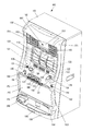
図1は、本発明の一実施形態に係るスロットマシン100の外観斜視図である。スロットマシン100は、メダルの投入により遊技が開始され、遊技の結果によりメダルが払い出されるものである。
(First embodiment)
<Overall configuration>
FIG. 1 is an external perspective view of a slot machine 100 according to an embodiment of the present invention. In the slot machine 100, a game is started when a medal is inserted, and a medal is paid out according to the result of the game.

スロットマシン100は、略箱状の本体101と、この本体101の前面開口部に取り付けられた前面扉102とを有して構成されている。スロットマシン100の本体101の中央内部には、外周面に複数種類の図柄が所定コマ数だけ配置されたリールが3個(左リール110、中リール111、右リール112)収納され、スロットマシン100の内部で回転できるように構成されている。各図柄は帯状部材に等間隔で適当数印刷され、この帯状部材が所定の円形枠材に貼り付けられて各リール110〜112が構成されている。リール110〜112上の図柄は、遊技者から見ると、図柄表示窓113から縦方向に概ね3つ表示され、合計9つの図柄が見えるようになっている。そして、各リール110〜112を回転させることにより、遊技者から見える図柄の組み合せが変動することとなる。なお、本実施形態では、3個のリールをスロットマシン100の中央内部に備えているが、リールの数やリールの設置位置はこれに限定されるものではない。   The slot machine 100 includes a substantially box-shaped main body 101 and a front door 102 attached to the front opening of the main body 101. Inside the center of the main body 101 of the slot machine 100, three reels (left reel 110, middle reel 111, and right reel 112) having a plurality of types of symbols arranged on the outer peripheral surface for a predetermined number of frames are stored. It is configured to be able to rotate inside. Each of the symbols is printed on the belt-like member at an appropriate interval, and the reels 110 to 112 are configured by sticking the belt-like member to a predetermined circular frame member. When viewed from the player, three symbols on the reels 110 to 112 are displayed in the vertical direction from the symbol display window 113 so that a total of nine symbols can be seen. Then, by rotating the reels 110 to 112, the combination of symbols that can be seen by the player varies. In the present embodiment, three reels are provided in the center of the slot machine 100, but the number of reels and the installation position of the reels are not limited to this.

また、図柄表示窓113の外枠には、点滅や点灯などの点灯制御によって、後述する有効ラインや入賞ラインを報知するためのライン表示LED(図示省略)が配置されている。   Further, on the outer frame of the symbol display window 113, line display LEDs (not shown) for informing an effective line and a winning line, which will be described later, are arranged by lighting control such as blinking and lighting.

さらに、スロットマシン100内部において各々のリール110〜112の近傍には、投光部と受光部からなる光学式センサ(図示省略)が設けられており、この光学式センサの投光部と受光部の間を、リールに設けられた一定の長さの遮光片が通過するように構成されている。このセンサの検出結果に基づいてリール上の図柄の回転方向の位置を判断し、目的とする図柄が入賞ライン114上に表示されるようにリール110〜112を停止させる。   Further, in the slot machine 100, an optical sensor (not shown) including a light projecting unit and a light receiving unit is provided in the vicinity of each of the reels 110 to 112. The light projecting unit and the light receiving unit of the optical sensor. A light-shielding piece of a certain length provided on the reel passes between them. Based on the detection result of the sensor, the position of the symbol on the reel in the rotation direction is determined, and the reels 110 to 112 are stopped so that the target symbol is displayed on the winning line 114.

入賞ライン表示ランプ120は、有効となる入賞ラインを示すランプである。有効となる入賞ラインは、スロットマシン100に投入されたメダルの数によって予め定まっている。5本の入賞ライン114のうち、例えば、メダルが1枚投入された場合、中段の水平入賞ラインが有効となり、メダルが2枚投入された場合、上段水平入賞ラインと下段水平入賞ラインが追加された3本が有効となり、メダルが3枚投入された場合、右下り入賞ラインと右上り入賞ラインが追加された5本が入賞ラインとして有効になる。なお、入賞ライン114の数については5本に限定されるものではない。   The winning line display lamp 120 is a lamp that indicates an effective winning line. An effective winning line is determined in advance by the number of medals inserted into the slot machine 100. Of the five winning lines 114, for example, when one medal is inserted, the middle horizontal winning line is valid, and when two medals are inserted, the upper horizontal winning line and the lower horizontal winning line are added. When three medals are inserted and three medals are inserted, the five added with the right-down winning line and the upper-right winning line become effective as the winning line. Note that the number of winning lines 114 is not limited to five.

スタートランプ121は、リール110〜112が回転することができる状態にあることを遊技者に知らせるランプである。再遊技ランプ122は、前回の遊技において入賞役の一つである再遊技役に入賞した場合に、今回の遊技が再遊技可能であること(メダルの投入なしに、前回遊技で投入した枚数と同じ枚数のメダルを投入したものとして遊技可能であること)を遊技者に知らせるランプである。告知ランプ123は、後述する内部抽選において、特定の入賞役(例えば、BB(ビッグボーナス)やRB(レギュラーボーナス)等のボーナス)に内部当選していることを遊技者に知らせるランプである。メダル投入ランプ124は、メダルの投入が可能であることを知らせるランプである。
払出枚数表示器125は、何らかの入賞役に入賞した結果、遊技者に払出されるメダルの枚数を表示するための表示器である。遊技回数表示器126は、メダル投入時のエラー表示や、ビッグボーナスゲーム中(BBゲーム中)の遊技回数、所定の入賞役の入賞回数等を表示するための表示器である。貯留枚数表示器127は、スロットマシン100に電子的に貯留されているメダルの枚数を表示するための表示器である。リールパネルランプ128は、演出用のランプである。
The start lamp 121 is a lamp that informs the player that the reels 110 to 112 are in a state of being able to rotate. The replay lamp 122 indicates that the current game can be replayed when winning a replaying role, which is one of the winning roles in the previous game (the number of games inserted in the previous game without any medals being inserted) It is a lamp that informs the player that it is possible to play the game with the same number of medals inserted. The notification lamp 123 is a lamp that informs the player that a specific winning combination (for example, a bonus such as BB (big bonus) or RB (regular bonus)) is won internally in an internal lottery described later. The medal insertion lamp 124 is a lamp that notifies that a medal can be inserted.
The payout number display 125 is a display for displaying the number of medals to be paid out to the player as a result of winning a winning combination. The game number display 126 is an indicator for displaying an error display at the time of inserting a medal, the number of games during the big bonus game (in the BB game), the number of winnings of a predetermined winning combination, and the like. The stored number display 127 is a display for displaying the number of medals electronically stored in the slot machine 100. The reel panel lamp 128 is an effect lamp.

メダル投入ボタン(ベットボタン)130、131は、スロットマシン100に電子的に貯留されているメダル(クレジットという)を所定の枚数分投入するためのボタンである。本実施形態においては、メダル投入ボタン130が押下される毎に1枚ずつ最大3枚まで投入され、メダル投入ボタン131が押下されると3枚投入されるようになっている。メダル投入口134は、遊技を開始するに当たって遊技者がメダルを投入するための投入口である。すなわち、メダルの投入は、メダル投入ボタン130又は131により電子的に投入することもできるし、メダル投入口134から実際のメダルを投入することもできる。   The medal insertion buttons (bet buttons) 130 and 131 are buttons for inserting a predetermined number of medals (referred to as credits) stored electronically in the slot machine 100. In this embodiment, every time the medal insertion button 130 is pressed, a maximum of three are inserted one by one, and when the medal insertion button 131 is pressed, three are inserted. The medal slot 134 is an slot for a player to insert a medal when starting a game. That is, the medal can be inserted electronically by the medal insertion button 130 or 131, or an actual medal can be inserted from the medal insertion slot 134.

精算ボタン132は、スロットマシン100に電子的に貯留されたメダル及びベットされたメダル(ベットされているが、未だ遊技に使用されていないメダル)を精算し、メダル払出口155よりメダル受皿156に排出するためのボタンである。ここで、精算とは、遊技に使用する遊技媒体(例えば、メダル)を遊技者に返却することを意味し、遊技に使用する遊技媒体には、上述したように、電子的に貯留された遊技媒体と、ベットされているが未だ遊技に使用されていない遊技媒体と、を含んでもよいし、また、電子的に貯留された遊技媒体だけであってもよい。メダル返却ボタン133は、投入されたメダルが詰まった場合に押下してメダルを取り除くためのボタンである。   The settlement button 132 settles the medals electronically stored in the slot machine 100 and the medals that have been bet (medals that have been bet but have not yet been used in the game), and enters the medal tray 156 from the medal payout opening 155. It is a button for discharging. Here, settlement means returning a game medium (for example, a medal) used for the game to the player, and the game medium used for the game includes an electronically stored game as described above. Media and game media that have been bet but have not yet been used in the game may be included, or only electronically stored game media may be included. The medal return button 133 is a button that is pressed to remove a medal when the inserted medal is jammed.

スタートレバー135は、遊技の開始操作を行うためのレバー型のスイッチである。すなわち、メダル投入口134に所望する枚数のメダルを投入して、スタートレバー135を操作すると、これを契機としてリール110〜112が回転し、遊技が開始される。ストップボタンユニット136に設けられたストップボタン137〜139は、スタートレバー135の操作によって回転を開始したリール110〜112を個別に停止させるためのボタン型のスイッチであり、各リール110〜112に対応して設けられている。そして、いずれかのストップボタン137〜139を操作すると対応するいずれかのリール110〜112が停止することになる。   The start lever 135 is a lever-type switch for performing a game start operation. That is, when a desired number of medals are inserted into the medal insertion slot 134 and the start lever 135 is operated, the reels 110 to 112 are rotated as a trigger, and the game is started. Stop buttons 137 to 139 provided on the stop button unit 136 are button-type switches for individually stopping the reels 110 to 112 that have started rotating by operating the start lever 135, and correspond to the reels 110 to 112. Is provided. When any one of the stop buttons 137 to 139 is operated, any one of the corresponding reels 110 to 112 is stopped.

ドアキー孔140は、スロットマシン100の前面扉102のロックを解除するためのキーを挿入する孔である。メダル払出口155は、メダルを払出すための払出口である。メダル受皿156は、メダル払出口155から払出されたメダルを溜めるための器である。なお、メダル受皿156は、本実施形態では発光可能な受皿を採用している。   The door key hole 140 is a hole into which a key for unlocking the front door 102 of the slot machine 100 is inserted. The medal payout exit 155 is a payout exit for paying out medals. The medal tray 156 is a container for collecting medals paid out from the medal payout opening 155. In this embodiment, the medal tray 156 employs a tray that can emit light.

上部ランプ150、サイドランプ151、中央ランプ152、腰部ランプ153、下部ランプ154は、遊技を盛り上げるための装飾用のランプである。演出装置600は、例えば開閉自在な扉装置(シャッター)163が前面に取り付けられた液晶表示装置157を含み、この演出装置190には、例えば小役告知等の各種の情報が表示される。音孔160は、スロットマシン100内部に設けられているスピーカの音を外部に出力するための孔である。タイトルパネル162には、スロットマシン100を装飾するための図柄が描かれている。   The upper lamp 150, the side lamp 151, the center lamp 152, the waist lamp 153, and the lower lamp 154 are decorative lamps for exciting games. The effect device 600 includes, for example, a liquid crystal display device 157 with a door device (shutter) 163 that can be freely opened and closed attached to the front surface. The effect device 190 displays various information such as a small role notification. The sound hole 160 is a hole for outputting the sound of a speaker provided inside the slot machine 100 to the outside. On the title panel 162, a pattern for decorating the slot machine 100 is drawn.

<筐体内部の構成>
次に、スロットマシン100の筐体内部の構成について簡単に説明する。図2は、スロットマシン100の前面扉102を開放した状態(かつ、右側面板の下方一部を欠截した状態)の斜視図である。本体101の内部には、主基板収納ケース210、副制御基板収納ケース220及びリールユニット185や、図示を省略した電源ボックス、メダル払出装置180、メダル補助収納ケース240、中央スピーカユニット、外部中継端子板等の諸装置が配設されている。
<Internal housing configuration>
Next, a configuration inside the housing of the slot machine 100 will be briefly described. FIG. 2 is a perspective view of the slot machine 100 in a state where the front door 102 is opened (and a state where a lower part of the right side plate is omitted). Inside the main body 101, there are a main board storage case 210, a sub control board storage case 220 and a reel unit 185, a power supply box (not shown), a medal payout device 180, a medal auxiliary storage case 240, a central speaker unit, an external relay terminal. Various devices such as plates are provided.

リールユニット185は、樹脂製のケース221内にステッピングモータで駆動されるリール110〜112を個別に着脱可能に取り付けて構成している。そして、このリールユニット185は、ケース221により3本のリールをユニット化し、本体101に設けたリールユニット載置台278に対する着脱を容易に行えるように構成している。また、リールユニット載置台278の下部には、音通路277が取り付けられ、前面扉102が本体101に閉じられた状態で前面扉102に取り付けられた音通路268と組み合わさるように構成している。中央スピーカユニットから出力された音は、この音通路277および音通路268を通過して外部に出力される。   The reel unit 185 is configured by individually detachably attaching reels 110 to 112 driven by a stepping motor in a resin case 221. The reel unit 185 is configured such that three reels are unitized by the case 221 and can be easily attached to and detached from the reel unit mounting table 278 provided in the main body 101. In addition, a sound passage 277 is attached to the lower part of the reel unit mounting table 278, and is configured to be combined with a sound passage 268 attached to the front door 102 in a state where the front door 102 is closed to the main body 101. . The sound output from the central speaker unit passes through the sound path 277 and the sound path 268 and is output to the outside.

本体101の内部には、透明な樹脂ケースからなる基板収納ケースが、本体101を構成している後板の上部に取り付けられている。この主基板収納ケース210の内部空間には、スロットマシン100の全体的な制御を行う主制御部300を構成する電気部品を実装した主制御基板が収納されている。   Inside the main body 101, a substrate storage case made of a transparent resin case is attached to the upper part of the rear plate constituting the main body 101. In the internal space of the main board storage case 210, a main control board on which electric parts constituting the main control unit 300 that performs overall control of the slot machine 100 is mounted is stored.

また、図示を省略した電源ボックスは、本体101の後板の壁面に装着され、金属製ケースの内部に、スロットマシン100の諸装置へ必要な電力を供給するための電源基板が収納されている。   The power supply box (not shown) is mounted on the wall of the rear plate of the main body 101, and a power supply board for supplying necessary power to the various devices of the slot machine 100 is housed inside the metal case. .

さらに、本体101の内部下方には、メダルを払い出すためのメダル払出装置180(以下、ホッパー180ということがある)が配設されている。メダル払出装置180は、DCモータで駆動されメダルを1枚ずつ払い出すと共に、メダルを払い出す毎に検出信号を出力する払出装置本体182と、払出装置本体182にメダルを供給するとともにメダルを蓄積するメダルタンク181とで構成される。そして、メダル払出装置180の横には、メダル補助収納ケース240が置かれており、メダル払出装置180がメダルでいっぱいになると、余分なメダルは流れ落ち、このメダル補助収納ケース240内に蓄積される。   Further, a medal payout device 180 (hereinafter sometimes referred to as a hopper 180) for paying out medals is disposed below the inside of the main body 101. The medal payout device 180 is driven by a DC motor, pays out medals one by one, outputs a detection signal each time the medals are paid out, supplies medals to the payout device main body 182 and accumulates medals. And a medal tank 181. Next, a medal auxiliary storage case 240 is placed beside the medal payout device 180. When the medal payout device 180 is filled with medals, excess medals flow down and are accumulated in the medal auxiliary storage case 240. .

また、前記主制御基板及びリール110〜112の側方、すなわち向って左側の側板には、副制御部400を構成する電気部品を実装した副制御基板を収納した副基板収納ケース220が配設してある。   Further, on the side plate of the main control board and the reels 110 to 112, that is, on the left side plate, a sub board storage case 220 that stores the sub control board on which the electrical components constituting the sub control section 400 are mounted is disposed. It is.

一方、本体101の側板にヒンジ装置276を介して蝶着された前面扉102には、演出装置600、この演出装置600を制御する演出制御基板を収納した演出制御基板収納ケース274、上部スピーカ272、図柄表示窓113を有するリールパネル270、投入されたメダルを選別するためのメダルセレクタ170、このメダルセレクタ170が不正なメダル等をメダル受皿156に落下させる際にメダルが通過する通路266等が設けてある。メダルセレクタ170は、さらに、投入されたメダルをメダルタンク(バケット)181に案内する通路267を備えている。   On the other hand, the front door 102 hinged to the side plate of the main body 101 via the hinge device 276 has the effect device 600, an effect control board storage case 274 storing an effect control board for controlling the effect device 600, and an upper speaker 272. A reel panel 270 having a symbol display window 113, a medal selector 170 for selecting inserted medals, a passage 266 through which medals pass when the medal selector 170 drops illegal medals etc. on the medal tray 156, and the like. It is provided. The medal selector 170 further includes a passage 267 for guiding the inserted medal to the medal tank (bucket) 181.

<メダル払出装置>
次に、図3及び図4を参照して、メダル払出装置180の構成について詳しく説明する。ここで、図3(a)は、メダル払出装置180の外観斜視図であり、図3(b)は、メダル払出装置180の一部を欠截した断面斜視図である。また、図4は、スロットマシン100の内部に配設されたメダル払出装置180及びメダル補助収納ケース240を右側から見たときの側面図である。
<Medal payout device>
Next, the configuration of the medal payout device 180 will be described in detail with reference to FIGS. 3 and 4. Here, FIG. 3A is an external perspective view of the medal payout device 180, and FIG. 3B is a cross-sectional perspective view in which a part of the medal payout device 180 is omitted. FIG. 4 is a side view of the medal payout device 180 and the medal auxiliary storage case 240 disposed in the slot machine 100 when viewed from the right side.

メダル払出装置180の概略は、メダルを蓄積するメダルタンク181と、メダルをメダル払出口1811へ導く案内手段と、この案内手段を駆動させる駆動手段と、を備えている。   The outline of the medal payout device 180 includes a medal tank 181 for accumulating medals, guide means for guiding medals to the medal payout outlet 1811, and drive means for driving the guide means.

すなわち、メダル払出装置180が備えるメダルを蓄積するメダルタンク181は、上方が開口すると共に、底面1812が傾斜する箱状であって、底面1812にはメダルを案内手段へ導く導出口(図示せず)を有している。また、メダルをメダル払出口1811へ導く案内手段は、メダルが一枚ずつ嵌入する嵌入孔1823を備えるディスク1821であって、このディスク1821がモータ1831を駆動源として回転することにより、嵌入孔1823に嵌入しているメダルを、メダル払出口1811から排出させる。   That is, the medal tank 181 for accumulating medals provided in the medal payout device 180 has a box shape in which an upper portion is opened and a bottom surface 1812 is inclined. A lead-out port (not shown) for guiding medals to the guide means is provided on the bottom surface 1812. )have. The guiding means for guiding the medals to the medal payout opening 1811 is a disk 1821 provided with insertion holes 1823 into which the medals are inserted one by one, and the disk 1821 rotates with the motor 1831 as a drive source. The medals inserted in the medals are discharged from the medal payout exit 1811.

更に、メダルタンク181の側面には、当該メダルタンク181に収容しきれなくなったメダルを、メダル補助収納ケース240に排出するための排出口1813が開設してある。なお、モータ1831やディスク1821はフレーム1814に組み付けられており、ディスク1821を回転可能に支持している払出装置本体182も、傾斜状に位置しており、ディスク1821もまた傾斜面において回転するように構成してある。もちろん、ディスク1821を水平面において回転するように構成してもよい。また、メダルが一枚ずつ嵌入する嵌入孔1823は、切欠部であってもよい。   Further, on the side surface of the medal tank 181, a discharge port 1813 is provided for discharging medals that cannot be stored in the medal tank 181 to the medal auxiliary storage case 240. Note that the motor 1831 and the disk 1821 are assembled to the frame 1814, the dispensing device main body 182 that rotatably supports the disk 1821 is also inclined, and the disk 1821 also rotates on the inclined surface. It is configured. Of course, the disk 1821 may be configured to rotate in a horizontal plane. Further, the insertion hole 1823 into which medals are inserted one by one may be a notch.

また、本実施形態においては、島設備がメダル自動補給機能を備えており、メダル払出装置180には、図4に示すように、スロットマシン100の本体背板1011に穿設された取付孔を介して、メダル自動補給装置800の供給口801が挿入されているとともに、自動補給センサ803が配設されている。メダル自動補給装置800より供給されるメダルは、供給口801から下方に落下し、メダルタンク181内に蓄積される。自動補給センサ803は、メダルタンク181に蓄積されたメダルが所定量に達したか否かを検知するセンサであり、メダルタンク181内のメダルが不足し、メダル自動補給装置800がメダルを補給する際には、当該自動補給センサ803がメダルの所定量を検知するまでメダルを補給し、メダルが所定量に達すると、メダルの補給を停止するようになっている。なお、メダルタンク181からオーバーフローしたメダルは、排出口1813を介して、メダル補助収納ケース240に落下して、回収される。   In this embodiment, the island facility has an automatic medal replenishment function, and the medal payout device 180 has a mounting hole formed in the main body back plate 1011 of the slot machine 100 as shown in FIG. In addition, a supply port 801 of the automatic medal replenishment device 800 is inserted, and an automatic replenishment sensor 803 is provided. The medals supplied from the automatic medal supply device 800 fall downward from the supply port 801 and are accumulated in the medal tank 181. The automatic replenishment sensor 803 is a sensor that detects whether or not the medal accumulated in the medal tank 181 has reached a predetermined amount. The medal in the medal tank 181 is insufficient, and the automatic medal replenishment device 800 replenishes the medal. At this time, medals are replenished until the automatic replenishment sensor 803 detects a predetermined amount of medals, and when the medals reach a predetermined amount, the replenishment of medals is stopped. The medals that have overflowed from the medal tank 181 fall into the medal auxiliary storage case 240 via the discharge port 1813 and are collected.

<メダル補助収納ケース>
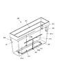
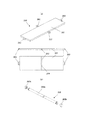
次に、図5〜図9を用いて、メダル補助収納ケース240の構成について説明する。図5は、メダル補助収納ケース240の外観斜視図であり、図6(a)は、メダル補助収納ケース240を本体101に設置した状態の外観斜視図、図6(b)は、メダル補助収納ケース240を本体101から取り外した状態の外観斜視図である。図7は、メダル補助収納ケース240及び本体底板1012の開口位置とメダル自動回収装置900の回収口901との位置関係を示す側面図であり、図7(a)は、前方位置にメダル自動回収装置900の回収口901が配設される場合、図7(b)は、後方位置にメダル自動回収装置900の回収口901が配設される場合の側面図である。図8は、メダル補助収納ケース240のケース底板260の外観図であり、図8(a)は、ケース底板260の外観斜視図、側面図、及び下面図であり、図8(b)は、ケース底板260の支持棒262の分解斜視図である。図9は、メダル補助収納ケース240のケース底板260が底面にメダル排出孔243を形成している状態を示す図であり、図9(a)は、後方底面にメダル排出孔243を形成している状態のメダル補助収納ケース240の外観斜視図、図9(b)は、前方底面及び後方底面にメダル排出孔243を形成したときのケース底板260のそれぞれの位置を示す側面図及びメダル排出孔243の位置を示す上面図である。
<Medal auxiliary storage case>
Next, the configuration of the medal auxiliary storage case 240 will be described with reference to FIGS. 5 is an external perspective view of the medal auxiliary storage case 240, FIG. 6A is an external perspective view of the medal auxiliary storage case 240 installed on the main body 101, and FIG. FIG. 3 is an external perspective view of a state where a case 240 is removed from the main body 101. FIG. 7 is a side view showing the positional relationship between the opening positions of the medal auxiliary storage case 240 and the main body bottom plate 1012 and the recovery port 901 of the automatic medal recovery device 900. FIG. 7A shows the automatic medal recovery at the front position. When the collection port 901 of the apparatus 900 is disposed, FIG. 7B is a side view when the collection port 901 of the automatic medal collection apparatus 900 is disposed at the rear position. 8 is an external view of the case bottom plate 260 of the medal auxiliary storage case 240, FIG. 8A is an external perspective view, a side view, and a bottom view of the case bottom plate 260, and FIG. 4 is an exploded perspective view of a support bar 262 of a case bottom plate 260. FIG. FIG. 9 is a diagram showing a state where the case bottom plate 260 of the medal auxiliary storage case 240 forms a medal discharge hole 243 on the bottom surface, and FIG. 9A shows a state where the medal discharge hole 243 is formed on the rear bottom surface. FIG. 9B is a side view showing the respective positions of the case bottom plate 260 when the medal discharge holes 243 are formed on the front bottom surface and the rear bottom surface, and the medal discharge holes. It is a top view which shows the position of 243. FIG.

メダル補助収納ケース240は、図5及び図6に示すように、本体101に着脱自在な、上方が開口するやや下すぼみの箱体であって、本体101に設置されるときは本体底板1012の上に載置される。   As shown in FIGS. 5 and 6, the medal auxiliary storage case 240 is a box that is detachable from the main body 101 and has a slightly lower opening that opens upward. When the medal auxiliary storage case 240 is installed in the main body 101, Placed on top.

詳しくは、メダル補助収納ケース240は、上方を開口し、メダルタンク181の排出口1813から排出されたメダルを取り入れるケース本体250と、ケース本体250の底面を形成するとともに、その底面にメダル排出口243を形成し、ケース本体250に取り入れたメダルをメダル自動回収装置900に案内するケース底板260と、を備えている。すなわち、メダル補助収納ケース240は、島設備がメダル自動回収機能を備えていない場合、及び備えている場合の双方に対応可能であり、島設備がメダル自動回収機能を備えていない場合には、ケース本体250の底面を閉じて、メダルを貯留させるメダル貯留庫としての機能を有する一方、島設備がメダル自動回収機能を備えている場合には、メダル自動回収装置900の回収口901に対応する位置に底面を開口させて、メダルタンク181から溢れたメダルをメダル自動回収装置900に誘導案内する案内部材としての機能を有している。   Specifically, the medal auxiliary storage case 240 is formed with a case main body 250 that opens upward and receives a medal discharged from the discharge port 1813 of the medal tank 181, and a bottom surface of the case main body 250, and a medal discharge port on the bottom surface. And a case bottom plate 260 for guiding medals taken into the case main body 250 to the automatic medal collection device 900. That is, the medal auxiliary storage case 240 can be used both when the island facility does not have the automatic medal collection function and when the island facility does not have the automatic medal collection function. When the bottom of the case main body 250 is closed and has a function as a medal storage for storing medals, when the island facility has an automatic medal recovery function, it corresponds to the recovery port 901 of the automatic medal recovery apparatus 900. It has a function as a guide member that opens a bottom surface at a position and guides and guides medals overflowing from the medal tank 181 to the automatic medal collection device 900.

なお、本実施形態では、図7に示すように、島設備はメダル自動回収機能を備えており、本体底板1012の下方には、回収口901を上方に向けたメダル自動回収装置900が配設されている。具体的には、図7(a)に示すように、前方位置に回収口901が配設されている場合には、メダル補助収納ケース240は、底面の前方位置にメダル回収孔243を開口させ、また、図7(b)に示すように、後方位置に回収口901が配設されている場合には、メダル補助収納ケース240は、底面の後方位置にメダル回収孔243を開口させて、メダルタンク181から溢れたメダルをメダル自動回収装置900に排出するようになっている。   In the present embodiment, as shown in FIG. 7, the island facility has an automatic medal collection function, and an automatic medal collection device 900 with a collection port 901 facing upward is disposed below the bottom plate 1012 of the main body. Has been. Specifically, as shown in FIG. 7A, when the recovery port 901 is disposed at the front position, the medal auxiliary storage case 240 opens the medal recovery hole 243 at the front position on the bottom surface. In addition, as shown in FIG. 7B, when the recovery port 901 is disposed at the rear position, the medal auxiliary storage case 240 opens the medal recovery hole 243 at the rear position on the bottom surface, The medals overflowing from the medal tank 181 are discharged to the medal automatic recovery device 900.

勿論、メダル補助収納ケース240を本体101に設置した状態において、メダル補助収納ケース240の底面下方に位置する本体底板1012上には、メダル自動回収装置900の回収口901(メダル補助収納ケース240のメダル回収孔243)の位置に合わせて、排出孔1013が穿設可能に形成されている。具体的には、メダル補助収納ケース240を載置する載置板としての本体底板1012は、図6(b)に示すように、前後方向に2つの排出孔1013a及び1013bを備えており、前方位置に回収口901が配設されている場合には、図6(b)及び図7(a)に示すように、排出孔1013aを穿設し、また、後方位置に回収口901が配設されている場合には、図6(b)及び図7(b)に示すように、排出孔1013bを穿設する。   Of course, in the state where the medal auxiliary storage case 240 is installed in the main body 101, the recovery port 901 (the medal auxiliary storage case 240 of the medal auxiliary storage case 240) is placed on the main body bottom plate 1012 located below the bottom surface of the medal auxiliary storage case 240. In accordance with the position of the medal recovery hole 243), a discharge hole 1013 is formed so as to be pierced. Specifically, as shown in FIG. 6B, the main body bottom plate 1012 as a placement plate on which the auxiliary medal storage case 240 is placed includes two discharge holes 1013a and 1013b in the front-rear direction. When the collection port 901 is disposed at the position, as shown in FIGS. 6B and 7A, the discharge hole 1013a is formed, and the collection port 901 is disposed at the rear position. In such a case, as shown in FIGS. 6B and 7B, a discharge hole 1013b is formed.

ケース本体250は、上方に開口241を有する断面略ロ字状の側面部251と、長手方向の両端部を除いてほぼ面全体に矩形の開口孔242を形成した底面部252と、から構成されている。側面部251のうち、一方の短手側面251aには、2つの挿通口253が穿設されており、図6に示すように、メダル補助収納ケース240をスロットマシン100の前面方向から本体101に設置する場合には、この挿通口253が形成された短手側面251aを後方に向けて、本体101に配設する。   The case main body 250 includes a side surface portion 251 having a substantially rectangular shape in cross section having an opening 241 on the upper side, and a bottom surface portion 252 in which a rectangular opening hole 242 is formed on substantially the entire surface except for both end portions in the longitudinal direction. ing. Two insertion ports 253 are formed in one short side surface 251a of the side surface portion 251, and the medal auxiliary storage case 240 is inserted into the main body 101 from the front side of the slot machine 100 as shown in FIG. When installing, it arrange | positions in the main body 101 with the short side surface 251a in which this insertion port 253 was formed facing back.

ケース本体250の短手側面251aに穿設された挿通口253には、図6に示すように、本体背板1011に配設されたオーバーフローセンサ327の接触端子751が挿通される。ここで、オーバーフローセンサ327は、メダル補助収納ケース240に貯留されたメダルが所定量に達したか否かを検知するセンサであり、メダル補助収納ケース240に貯留されたメダルがほぼ満杯になったときは、外部装置(ホールコンピュータ)に対してメダル満杯を示す信号を出力するようになっている。具体的には、メダル補助収納ケース240内のメダルが増えて、メダルが一対の接触端子751に接触すると両接触端子751は導通するので、この両接触端子751の導通により、スロットマシン100はメダル補助収納ケース240のメダル満杯を検知するようになっている。すなわち、オーバーフローセンサ327は、実質的には、島設備がメダル自動回収機能を備えていない場合であって、メダル補助収納ケース240の底面部252の開口孔242を閉じた状態で使用するときに有効に機能するものである。   As shown in FIG. 6, the contact terminal 751 of the overflow sensor 327 disposed in the main body back plate 1011 is inserted into the insertion port 253 formed in the short side surface 251 a of the case main body 250. Here, the overflow sensor 327 is a sensor that detects whether or not the medal stored in the medal auxiliary storage case 240 has reached a predetermined amount, and the medal stored in the medal auxiliary storage case 240 is almost full. At this time, a signal indicating that the medals are full is output to an external device (hall computer). Specifically, when the number of medals in the medal auxiliary storage case 240 increases and the medals come into contact with the pair of contact terminals 751, both contact terminals 751 become conductive. The medal fullness of the auxiliary storage case 240 is detected. That is, the overflow sensor 327 is substantially a case where the island facility does not have an automatic medal collection function and is used when the opening hole 242 of the bottom surface portion 252 of the medal auxiliary storage case 240 is closed. It functions effectively.

また、図5に示すように、メダル補助収納ケース240の両長手側面251bそれぞれには、対向位置にT字状の案内孔254が形成されており、ケース底板260の支持棒262が、この案内孔254に嵌合して、案内孔254上を移動可能となっている。この結果、ケース底板260は、支持棒262の動きに応じて、姿勢を変えつつケース本体250内を移動可能となっており、後述するように、ケース本体250に傾斜支持されることが可能である(図9参照)。なお、以下においては、案内孔254のうち、底面に垂直方向に形成された案内孔254を案内孔254a、水平方向に形成された案内孔254を案内孔254bと称して説明を行う。   Further, as shown in FIG. 5, a T-shaped guide hole 254 is formed in each of the long side surfaces 251b of the medal auxiliary storage case 240 at opposite positions, and the support bar 262 of the case bottom plate 260 is provided with this guide. It fits in the hole 254 and can move on the guide hole 254. As a result, the case bottom plate 260 can be moved in the case main body 250 while changing its posture in accordance with the movement of the support bar 262, and can be supported by the case main body 250 in an inclined manner as will be described later. Yes (see FIG. 9). In the following description, among the guide holes 254, the guide hole 254 formed in the vertical direction on the bottom surface is referred to as the guide hole 254a, and the guide hole 254 formed in the horizontal direction is referred to as the guide hole 254b.

ケース本体250の底面部252には、上述したように矩形状の開口孔242が穿設されており、図5に示すように、メダル補助収納ケース240の底面を全閉状態とする場合には、この開口孔242上にケース底板260が載置されて、開口孔242は塞がれるようになっている。一方、図9に示すように、メダル補助収納ケース240の底面を一部開口状態とする場合には、ケース底板260の長手方向の一端部を側面部251の上方開口縁に係止させるとともに、支持棒262を案内孔254bの一端または他端に係止させて、ケース底板260を傾斜支持し、開口孔242の一部をメダル排出孔243として形成するようになっている。なお、ケース底板260の配設位置とメダル排出孔243の形成位置の関係に関しては、詳しくは後述する。   As described above, the rectangular opening hole 242 is formed in the bottom surface portion 252 of the case main body 250, and when the bottom surface of the medal auxiliary storage case 240 is fully closed as shown in FIG. The case bottom plate 260 is placed on the opening hole 242, and the opening hole 242 is closed. On the other hand, as shown in FIG. 9, when the medal auxiliary storage case 240 is partially opened, the longitudinal end of the case bottom plate 260 is locked to the upper opening edge of the side surface 251, The support bar 262 is locked to one end or the other end of the guide hole 254b to support the case bottom plate 260 in an inclined manner, and a part of the opening hole 242 is formed as a medal discharge hole 243. The relationship between the arrangement position of the case bottom plate 260 and the formation position of the medal discharge hole 243 will be described later in detail.

ケース底板260は、図8に示すように、矩形状のプレート261と、プレート261の長手側面中央を短手方向に貫通する支持棒262と、プレート261の長手方向両端からそれぞれL字状に下方に突設された係止突部263と、を備えている。   As shown in FIG. 8, the case bottom plate 260 includes a rectangular plate 261, a support bar 262 that penetrates the center of the longitudinal side surface of the plate 261 in the lateral direction, and a L-shaped downward from both longitudinal ends of the plate 261. And a locking projection 263 projecting from the top.

プレート261は、開口孔242全体を覆う大きさを有する矩形状の金属または樹脂プレートであり、長手側面中央には、支持棒262を挿通させるための貫通孔264が形成されている。   The plate 261 is a rectangular metal or resin plate having a size covering the entire opening hole 242, and a through-hole 264 for inserting the support rod 262 is formed at the center of the long side surface.

支持棒262は、金属製の棒であり、さらに詳しくは、図8(b)に示すように、円筒状の支持棒本体262aと、支持棒本体262の両先端に螺合される円筒キャップ状の抜止部材262bと、から構成され、抜止部材262bの外径は支持棒本体262aの外径よりもやや大きく形成されている。すなわち、支持棒本体262aの外径は、案内孔254及び貫通孔264の内径よりもやや小さく形成される一方、抜止部材262bの外径は、案内孔254及び貫通孔264の内径よりもやや大きく形成されているので、支持棒262はプレート261から抜脱不可能であるとともに、支持棒262が案内孔254に沿って移動する際には、ケース底板260はケース本体251から抜脱不可能となっている。   The support rod 262 is a metal rod, and more specifically, as shown in FIG. 8B, a cylindrical support rod body 262a and a cylindrical cap shape screwed to both ends of the support rod body 262. And the outer diameter of the retaining member 262b is slightly larger than the outer diameter of the support bar body 262a. That is, the outer diameter of the support bar main body 262a is formed to be slightly smaller than the inner diameters of the guide hole 254 and the through hole 264, while the outer diameter of the retaining member 262b is slightly larger than the inner diameters of the guide hole 254 and the through hole 264. Since the support bar 262 cannot be removed from the plate 261, the case bottom plate 260 cannot be removed from the case body 251 when the support bar 262 moves along the guide hole 254. It has become.

なお、ケース底板260をケース本体250に取り付けるときは、まず、プレート261をケース本体250の開口241から底面部252に載置し、次いで、プレート261の貫通孔264を案内孔254aの位置に合わせて、支持棒本体262aを案内孔254a及び貫通孔264に挿通し、支持棒本体262aを案内孔254a及び貫通孔264に挿通して支持棒本体262aをケース本体250から突出させた状態で、長手側面251bの外側から抜止部材262bを支持棒本体262aに螺合して固定する。   When attaching the case bottom plate 260 to the case main body 250, first, the plate 261 is placed on the bottom surface portion 252 from the opening 241 of the case main body 250, and then the through hole 264 of the plate 261 is aligned with the position of the guide hole 254a. The support bar body 262a is inserted into the guide hole 254a and the through hole 264, the support bar body 262a is inserted into the guide hole 254a and the through hole 264, and the support bar body 262a is protruded from the case body 250 in the longitudinal direction. The retaining member 262b is screwed and fixed to the support bar main body 262a from the outside of the side surface 251b.

このように本実施形態においては、ケース底板260は、ケース本体250に着脱可能であるが、案内孔254に沿って移動及び支持される限りにおいては、ケース本体250から抜脱不可能となっている。   As described above, in the present embodiment, the case bottom plate 260 can be attached to and detached from the case main body 250. However, as long as the case bottom plate 260 is moved and supported along the guide hole 254, it cannot be removed from the case main body 250. Yes.

次に、図9を用いて、ケース底板260の配設位置とメダル排出孔243の形成位置との関係について、詳しく説明する。   Next, the relationship between the position where the case bottom plate 260 is disposed and the position where the medal discharge hole 243 is formed will be described in detail with reference to FIG.

図9(a)及び(b)の左側に示すように、ケース底板260の支持棒262が案内孔254bの前方側一端P2に係止して支持されるときは、ケース底板260の係止突部263がケース本体250の前方側の短手側面251aの上端に係止されて、ケース底板260は斜めの姿勢となるので、底面部252の開口孔242の後方半分が開口されたメダル排出孔243が形成されるとともに、ケース底板260はメダルをメダル排出孔243に導く傾斜案内路となっている。   As shown on the left side of FIGS. 9A and 9B, when the support bar 262 of the case bottom plate 260 is supported by being locked to the front end P2 of the guide hole 254b, the locking protrusion of the case bottom plate 260 is supported. Since the portion 263 is locked to the upper end of the short side surface 251a on the front side of the case main body 250, the case bottom plate 260 is inclined, so that the medal discharge hole in which the rear half of the opening hole 242 of the bottom surface portion 252 is opened. 243 is formed, and the case bottom plate 260 is an inclined guide path that guides the medal to the medal discharge hole 243.

一方、図9(b)の右側に示すように、ケース底板260の支持棒262が案内孔254bの後方側一端P3に係止して支持されるときは、ケース底板260の係止突部263がケース本体250の後方側の短手側面250aの上端に係止されて、ケース底板260は斜めの姿勢となるので、底面部252の開口孔242の前方半分が開口されたメダル排出孔243が形成されるとともに、ケース底板260はメダルをメダル排出孔243に導く傾斜案内路となっている。   On the other hand, as shown on the right side of FIG. 9B, when the support bar 262 of the case bottom plate 260 is locked and supported by the rear end P3 of the guide hole 254b, the locking protrusion 263 of the case bottom plate 260 is supported. Is locked to the upper end of the short side surface 250a on the rear side of the case body 250, and the case bottom plate 260 assumes an oblique posture, so that the medal discharge hole 243 in which the front half of the opening hole 242 of the bottom surface portion 252 is opened is formed. The case bottom plate 260 is formed as an inclined guide path that guides the medal to the medal discharge hole 243.

このように本実施形態においては、ケース底板260の配設位置に応じて、開口位置が異なる2つのメダル排出孔243を形成することができる。すなわち、図7に示すように、メダル自動回収装置900の回収口901の位置に応じて、ケース底板260の配設位置を設定することにより、回収口901の位置に応じたメダル排出孔243を形成することができる。なお、図9に示す2つのメダル排出孔243は、開口位置は前後に異なるが、開口面積は同一である。   Thus, in the present embodiment, two medal discharge holes 243 having different opening positions can be formed according to the arrangement position of the case bottom plate 260. That is, as shown in FIG. 7, by setting the position of the case bottom plate 260 according to the position of the recovery port 901 of the automatic medal collection device 900, the medal discharge hole 243 corresponding to the position of the recovery port 901 is set. Can be formed. Note that the opening positions of the two medal discharge holes 243 shown in FIG. 9 are the same, but the opening areas are the same.

また、本実施形態においては、ケース底板260の支持棒262は、T字状の案内孔254上、すなわち、ケース本体250の開口孔242を全閉とする第1位置(P1)からケース本体250の開口孔242を一部開口させる第2位置(P2、P3)との間の経路上を移動可能となっているが、経路上ではケース本体250から脱抜不可能に構成しているので、ケース底板260を移動させて開口位置が異なるメダル排出孔243を形成しつつも、ケース底板260を紛失することがない。   Further, in this embodiment, the support bar 262 of the case bottom plate 260 is placed on the T-shaped guide hole 254, that is, from the first position (P1) where the opening hole 242 of the case body 250 is fully closed. It is possible to move on the path between the second position (P2, P3) where a part of the opening hole 242 is partially opened, but it is configured so that it cannot be removed from the case body 250 on the path. The case bottom plate 260 is not lost while the medal discharge hole 243 having a different opening position is formed by moving the case bottom plate 260.

なお、本実施形態においては、支持棒262の両先端に円筒キャップ状の抜止部材262bを設けることにより、支持棒262が案内孔254から抜け出ないようにしたが、支持棒262が案内孔254から抜け出ない機構であれば、抜止部材262bはいかなる形状及び部材であってもよい。例えば、支持棒262の両先端に形成された挿入孔に割ピンを差し込むことによって、支持棒262の両先端に突出部を設け、これによって支持棒262が案内孔254から抜け出ないようにしてもよい。   In this embodiment, the cylindrical cap-shaped retaining member 262b is provided at both ends of the support bar 262 so that the support bar 262 does not come out of the guide hole 254. However, the support bar 262 is removed from the guide hole 254. As long as the mechanism does not come out, the retaining member 262b may have any shape and shape. For example, by inserting split pins into the insertion holes formed at both ends of the support bar 262, protrusions are provided at both ends of the support bar 262 so that the support bar 262 does not come out of the guide hole 254. Good.

また、本実施形態においては、ケース底板260の配設位置に応じて開口位置が異なる2つのメダル排出孔243を形成したが、開口位置は2つに限定されるものではなく、3つ以上のメダル排出孔243を形成するように案内孔254を構成してもよい。   In the present embodiment, the two medal discharge holes 243 having different opening positions are formed according to the arrangement position of the case bottom plate 260. However, the opening positions are not limited to two, and three or more opening positions are not limited. The guide hole 254 may be configured to form the medal discharge hole 243.

図10は、メダル排出孔243の開口位置が4箇所形成可能なメダル補助収納ケース240Aの側面図であり、後方側にメダル排出孔243を形成するときの底板250の位置とメダル排出孔243の関係を示している。   FIG. 10 is a side view of the medal auxiliary storage case 240A in which the opening positions of the medal discharge holes 243 can be formed at four locations. The positions of the bottom plate 250 and the medal discharge holes 243 when the medal discharge holes 243 are formed on the rear side. Showing the relationship.

図10に示した案内孔254Aは、概略T字状の孔を形成しているが、支持棒260が係止支持される支持位置を4つ(具体的には、P2、P3、P4、及びP5の4つ)備えている。詳しくは、P2、P3、P4、及びP5は、それぞれ、水平方向に形成された案内孔254Abから下方に突出して穿設された孔の下端に位置し、P2及びP3は、案内孔254Abの一端及び他端に形成され、P4はP2よりも長手方向やや中央寄り、P5はP3よりも長手方向やや中央寄りに形成されている。なお、図10には支持棒260をP2及びP4で支持したときのメダル排出孔243の形成位置を示しているが、P3及びP5で支持したときも同様であり、メダル排出孔243の前後方向の位置が異なるだけである。   The guide hole 254A shown in FIG. 10 forms a substantially T-shaped hole, but has four support positions (specifically, P2, P3, P4, and 4 of P5). Specifically, P2, P3, P4, and P5 are respectively positioned at the lower ends of holes that project downward from the guide hole 254Ab formed in the horizontal direction, and P2 and P3 are one end of the guide hole 254Ab. P4 is formed slightly closer to the center than P2, and P5 is formed slightly closer to the center than P3. 10 shows the formation position of the medal discharge hole 243 when the support rod 260 is supported by P2 and P4, but the same applies when supported by P3 and P5. The position of is different.

詳しくは、図10に示すように、ケース底板260の支持棒262が案内孔254AのP2に係止して支持されるときは、ケース底板260の係止突部263がケース本体250の短手側面250aの上端に係止され、ケース底板260の支持棒262が案内孔254AのP4に係止して支持されるときは、ケース底板260の係止突部263がケース本体250の短手側面250aの段差部255に係止されて、ケース底板260はケース本体250Aに傾斜支持される。   Specifically, as shown in FIG. 10, when the support bar 262 of the case bottom plate 260 is supported by being supported by P <b> 2 of the guide hole 254 </ b> A, the locking projection 263 of the case bottom plate 260 is the short side of the case main body 250. When the support bar 262 of the case bottom plate 260 is locked to and supported by P4 of the guide hole 254A and is locked to the upper end of the side surface 250a, the locking projection 263 of the case bottom plate 260 is the short side surface of the case body 250. The case bottom plate 260 is supported by the case main body 250 </ b> A by being latched by the stepped portion 255 of 250 a.

この結果、メダル補助収納ケース240Aは、それぞれの支持位置に応じて、開口位置が異なる4つのメダル排出孔243を形成することができる。なお、本変形例では、図10に示すように、開口位置だけでなく、開口面積も異ならせたメダル排出孔243を形成することができる。   As a result, the medal auxiliary storage case 240A can form four medal discharge holes 243 having different opening positions according to the respective support positions. In this modified example, as shown in FIG. 10, not only the opening position but also the medal discharge hole 243 having different opening areas can be formed.

<制御部の回路構成>
次に、図11および図12を用いて、スロットマシン100の制御部の回路構成について説明する。
<Circuit configuration of control unit>
Next, the circuit configuration of the control unit of the slot machine 100 will be described with reference to FIGS. 11 and 12.

スロットマシン100の制御部は、大別すると、遊技の中枢部分の制御、すなわち、スロットマシン100の遊技進行に関する処理を実行する主制御部300と、主制御部300より送信された信号(制御コマンド)に応じて各種機器を制御、すなわち、演出に関する処理を実行する副制御部400と、によって構成されている。   The control unit of the slot machine 100 can be broadly divided into a main control unit 300 that performs control of the central part of the game, that is, processing related to the game progress of the slot machine 100, and a signal (control command) transmitted from the main control unit 300. ) To control various devices, that is, the sub-control unit 400 that executes processing related to effects.

<主制御部>
まず、図11を用いて、スロットマシン100の主制御部300について説明する。なお、同図は主制御部300の回路ブロック図を示したものである。
<Main control unit>
First, the main control unit 300 of the slot machine 100 will be described with reference to FIG. The figure shows a circuit block diagram of the main control unit 300.

主制御部300は、主制御部300の全体を制御するための演算処理装置であるCPU310や、CPU310が各ICや各回路と信号の送受信を行うためのデータバス及びアドレスバスを備え、その他、以下に述べる構成を有する。クロック補正回路314は、水晶発振器311から発振されたクロックを分周してCPU310に供給する回路である。例えば、水晶発振器311の周波数が12MHzの場合に、分周後のクロックは6MHzとなる。CPU310は、クロック補正回路314により分周されたクロックをシステムクロックとして受け入れて動作する。   The main control unit 300 includes a CPU 310 that is an arithmetic processing unit for controlling the entire main control unit 300, a data bus and an address bus for the CPU 310 to transmit and receive signals to and from each IC and each circuit, It has the structure described below. The clock correction circuit 314 is a circuit that divides the clock oscillated from the crystal oscillator 311 and supplies it to the CPU 310. For example, when the frequency of the crystal oscillator 311 is 12 MHz, the divided clock is 6 MHz. The CPU 310 operates by receiving the clock divided by the clock correction circuit 314 as a system clock.

また、CPU310には、センサやスイッチの状態を常時監視するためのタイマ割り込み処理の周期やモータの駆動パルスの送信周期を設定するためのタイマ回路315がバスを介して接続されている。CPU310は、電源が投入されると、データバスを介してROM312の所定エリアに格納された分周用のデータをタイマ回路315に送信する。タイマ回路315は、受信した分周用のデータを基に割り込み時間を決定し、この割り込み時間ごとに、割り込み要求をCPU310に送信する。CPU310は、この割込み要求を契機に、各センサ等の監視や駆動パルスの送信を実行する。例えば、CPU310のシステムクロックを8MHz、タイマ回路315の分周値を1/256、ROM312の分周用のデータを47に設定した場合、この割り込みの基準時間は、256×47÷8MHz=1.504msとなる。   The CPU 310 is connected to a timer circuit 315 for setting a timer interrupt processing cycle for constantly monitoring the sensor and switch states and a motor drive pulse transmission cycle via a bus. When the power is turned on, the CPU 310 transmits the frequency dividing data stored in the predetermined area of the ROM 312 to the timer circuit 315 via the data bus. The timer circuit 315 determines an interrupt time based on the received frequency division data, and transmits an interrupt request to the CPU 310 at each interrupt time. In response to this interrupt request, the CPU 310 executes monitoring of each sensor and transmission of drive pulses. For example, when the system clock of the CPU 310 is set to 8 MHz, the frequency division value of the timer circuit 315 is set to 1/256, and the data for frequency division of the ROM 312 is set to 47, the reference time for this interrupt is 256 × 47 ÷ 8 MHz = 1. 504 ms.

さらに、CPU310には、各ICを制御するためのプログラム、入賞役の内部抽選時に用いる抽選データ、リールの停止位置等の各種データを記憶しているROM312や、一時的なデータを保存するためのRAM313が接続されている。これらのROM312やRAM313については他の記憶手段を用いてもよく、この点は後述する副制御部400においても同様である。また、CPU310には、外部の信号を受信するための入力インタフェース360が接続され、割込み時間ごとに入力インタフェース360を介して、メダル投入センサ320、スタートレバーセンサ321、ストップボタンセンサ322、メダル投入ボタンセンサ323、精算スイッチセンサ324、メダル払い出しセンサ326、オーバーフローセンサ327、及びリセットスイッチ328の状態を検出し、各センサを監視している。   Further, the CPU 310 stores a ROM 312 for storing various data such as a program for controlling each IC, lottery data used for internal winning lottery, reel stop position, and temporary data. A RAM 313 is connected. Other storage means may be used for these ROM 312 and RAM 313, and this is the same in the sub-control unit 400 described later. The CPU 310 is connected to an input interface 360 for receiving an external signal. The medal insertion sensor 320, the start lever sensor 321, the stop button sensor 322, and the medal insertion button are connected via the input interface 360 at every interruption time. The state of the sensor 323, the settlement switch sensor 324, the medal payout sensor 326, the overflow sensor 327, and the reset switch 328 is detected, and each sensor is monitored.

メダル投入センサ320は、メダル投入口134の内部の通路に設置されており、メダル投入口134に投入されたメダルを検出するためのセンサである。スタートレバーセンサ321はスタートレバー135の操作を検出するためのセンサである。ストップボタンセンサ322はストップボタン137〜139のいずれかが押された場合、どのストップボタンが押されたかを検出するためのセンサである。メダル投入ボタンセンサ323はメダル投入ボタン130、131のいずれかが押下された場合、どのメダル投入ボタンが押されたかを検出するためのセンサである。精算スイッチセンサ324は、精算ボタン132に設けられており、精算ボタン132が一回押されると、貯留されているメダル及びベットされているメダル(ベットされているが、未だ遊技に使用されていないメダル)が精算されて払い出されることになる。メダル払い出しセンサ326は、払い出されるメダルを検出するためのセンサである。オーバーフローセンサ327は、メダル補助収納ケース240に収納されたメダルのオーバーフローを検出するためのセンサである。リセットスイッチ328は、RAM313に記憶されている情報を初期化するためのスイッチである。   The medal insertion sensor 320 is installed in a passage inside the medal insertion slot 134 and is a sensor for detecting a medal inserted into the medal insertion slot 134. The start lever sensor 321 is a sensor for detecting the operation of the start lever 135. The stop button sensor 322 is a sensor for detecting which stop button is pressed when any one of the stop buttons 137 to 139 is pressed. The medal insertion button sensor 323 is a sensor for detecting which medal insertion button is pressed when one of the medal insertion buttons 130 and 131 is pressed. The settlement switch sensor 324 is provided on the settlement button 132, and when the settlement button 132 is pressed once, a stored medal and a bet medal (although betted but not yet used in a game) Medals) will be settled and paid out. The medal payout sensor 326 is a sensor for detecting a payout medal. The overflow sensor 327 is a sensor for detecting an overflow of medals stored in the medal auxiliary storage case 240. The reset switch 328 is a switch for initializing information stored in the RAM 313.

CPU310には、更に、入力インタフェース361、出力インタフェース370及び371がアドレスデコード回路350を介してアドレスバスに接続されている。CPU310は、これらのインタフェースを介して外部のデバイスと信号の送受信を行っている。   In addition, an input interface 361 and output interfaces 370 and 371 are connected to the CPU 310 via the address decoding circuit 350 to the address bus. The CPU 310 exchanges signals with external devices via these interfaces.

入力インタフェース361には、インデックスセンサ325が接続されている。インデックスセンサ325は、各リール110〜112の取付台の所定位置に設置されており、リール110〜112に設けた遮光片がこのインデックスセンサ325を通過するたびにハイレベルになる。CPU310は、この信号を検出すると、リールが1回転したものと判断し、リールの回転位置情報をゼロにリセットする。   An index sensor 325 is connected to the input interface 361. The index sensor 325 is installed at a predetermined position on the mounting base of each of the reels 110 to 112, and becomes a high level every time the light shielding piece provided on the reels 110 to 112 passes through the index sensor 325. When detecting this signal, the CPU 310 determines that the reel has made one rotation, and resets the rotational position information of the reel to zero.

出力インタフェース370には、リールを駆動させるためのモータを制御するリールモータ駆動部330と、ホッパー(メダル払出装置180)のモータを駆動するためのホッパーモータ駆動部331と、遊技ランプ340(具体的には、入賞ライン表示ランプ120、スタートランプ121、再遊技ランプ122、告知ランプ123、メダル投入ランプ124等)と、7セグメント(SEG)表示器341(払出枚数表示器125、遊技回数表示器126、貯留枚数表示器127、7セグ表示器等)が接続されている。   The output interface 370 includes a reel motor driving unit 330 that controls a motor for driving a reel, a hopper motor driving unit 331 for driving a motor of a hopper (medal payout device 180), and a game lamp 340 (specifically Are a winning line display lamp 120, a start lamp 121, a re-game lamp 122, a notification lamp 123, a medal insertion lamp 124, etc., and a 7-segment (SEG) display 341 (a payout number display 125, a game number display 126). Storage number display 127, 7-segment display, etc.) are connected.

また、CPU310には、乱数発生回路317がデータバスを介して接続されている。乱数発生回路317は、水晶発振器311及び水晶発振器316から発振されるクロックに基づいて、一定の範囲内で値をインクリメントし、そのカウント値をCPU310に出力することのできるインクリメントカウンタであり、後述する入賞役の内部抽選をはじめ各種抽選処理に使用される。   A random number generation circuit 317 is connected to the CPU 310 via a data bus. The random number generation circuit 317 is an increment counter capable of incrementing a value within a certain range based on a clock oscillated from the crystal oscillator 311 and the crystal oscillator 316 and outputting the count value to the CPU 310, which will be described later. Used for various lottery processes, including internal lottery for winning positions.

CPU310のデータバスには、副制御部400にコマンドを送信するための出力インタフェース371が接続されている。主制御部300と副制御部400との情報通信は一方向の通信であり、主制御部300は副制御部400へコマンドを送信するが、副制御部400から主制御部300へ何らかのコマンド等を送信することはできない。   An output interface 371 for transmitting a command to the sub control unit 400 is connected to the data bus of the CPU 310. Information communication between the main control unit 300 and the sub control unit 400 is a one-way communication, and the main control unit 300 transmits a command to the sub control unit 400. Cannot be sent.

<副制御部>
次に、図12を用いて、スロットマシン100の副制御部400について説明する。なお、同図は副制御部400の回路ブロック図を示したものである。
<Sub control unit>
Next, the sub control unit 400 of the slot machine 100 will be described with reference to FIG. This figure shows a circuit block diagram of the sub-control unit 400.

副制御部400は、主制御部300より送信された主制御コマンド等に基づいて副制御部400の全体を制御する演算処理装置であるCPU410や、CPU410が各IC、各回路と信号の送受信を行うためのデータバス及びアドレスバスを備え、以下に述べる構成を有する。クロック補正回路414は、水晶発振器411から発振されたクロックを補正し、補正後のクロックをシステムクロックとしてCPU410に供給する回路である。   The sub-control unit 400 is an arithmetic processing unit that controls the entire sub-control unit 400 based on a main control command or the like transmitted from the main control unit 300, and the CPU 410 transmits and receives signals to and from each IC and each circuit. It has a data bus and an address bus for performing, and has a configuration described below. The clock correction circuit 414 is a circuit that corrects the clock oscillated from the crystal oscillator 411 and supplies the corrected clock to the CPU 410 as a system clock.

また、CPU410にはタイマ回路415がバスを介して接続されている。CPU410は、所定のタイミングでデータバスを介してROM412の所定エリアに格納された分周用のデータをタイマ回路415に送信する。タイマ回路415は、受信した分周用のデータを基に割り込み時間を決定し、この割り込み時間ごとに、割り込み要求をCPU410に送信する。CPU410は、この割込み要求のタイミングをもとに、各ICや各回路を制御する。   Further, a timer circuit 415 is connected to the CPU 410 via a bus. The CPU 410 transmits the frequency dividing data stored in the predetermined area of the ROM 412 to the timer circuit 415 via the data bus at a predetermined timing. The timer circuit 415 determines an interrupt time based on the received frequency division data, and transmits an interrupt request to the CPU 410 at each interrupt time. The CPU 410 controls each IC and each circuit based on the interrupt request timing.

また、CPU410には、副制御部400の全体を制御するための命令及びデータ、ライン表示LEDの点灯パターンや各種表示器を制御するためのデータが記憶されたROM412や、データ等を一時的に保存するためのRAM413が各バスを介して接続されている。   Further, the CPU 410 temporarily stores a ROM 412 in which commands and data for controlling the entire sub-control unit 400, line lighting LED lighting patterns and data for controlling various displays, and the like are stored. A RAM 413 for storage is connected via each bus.

さらに、CPU410には、外部の信号を送受信するための入出力インタフェース460が接続されており、入出力インタフェース460には、図柄表示窓113の外枠に配設され、点滅や点灯などの点灯制御によって有効ラインや入賞ラインを報知するためのライン表示LED420、前面扉102の開閉を検出するための扉センサ421、RAM413に記憶されている情報を初期化するリセットスイッチ422が接続されている。   Further, an input / output interface 460 for transmitting and receiving external signals is connected to the CPU 410. The input / output interface 460 is disposed on the outer frame of the symbol display window 113 and controls lighting such as blinking and lighting. Are connected to a line display LED 420 for informing an active line or a winning line, a door sensor 421 for detecting opening / closing of the front door 102, and a reset switch 422 for initializing information stored in the RAM 413.

CPU410には、データバスを介して主制御部300から主制御コマンドを受信するための入力インタフェース461が接続されており、入力インタフェース461を介して受信したコマンドに基づいて、遊技全体を盛り上げる演出処理が実行される。また、CPU410のデータバスとアドレスバスには、音源IC480が接続されている。音源IC480は、CPU410からの命令に応じて音声の制御を行う。また、音源IC480には、音声データが記憶されたROM481が接続されており、音源IC480は、ROM481から取得した音声データをアンプ482で増幅させてスピーカ483から出力する。CPU410には、主制御部300と同様に、外部ICを選択するためのアドレスデコード回路450が接続されており、アドレスデコード回路450には、主制御部300からのコマンドを受信するための入力インタフェース461、時計IC423、7セグメント表示器440への信号を出力するための出力インタフェース472等が接続されている。   An input interface 461 for receiving a main control command from the main control unit 300 is connected to the CPU 410 via a data bus, and an effect process that excites the entire game based on the command received via the input interface 461. Is executed. A sound source IC 480 is connected to the data bus and address bus of the CPU 410. The sound source IC 480 controls sound according to a command from the CPU 410. The sound source IC 480 is connected to a ROM 481 that stores sound data. The sound source IC 480 amplifies the sound data acquired from the ROM 481 by the amplifier 482 and outputs the sound data from the speaker 483. The CPU 410 is connected to an address decoding circuit 450 for selecting an external IC, similar to the main control unit 300, and the input interface for receiving a command from the main control unit 300 is connected to the address decoding circuit 450. 461, a clock IC 423, an output interface 472 for outputting signals to the 7-segment display 440, and the like are connected.

時計IC423が接続されていることで、CPU410は、現在時刻を取得することが可能である。7セグメント表示器440は、スロットマシン100の内部に設けられており、たとえば副制御部400に設定された所定の情報を遊技店の係員等が確認できるようになっている。更に、出力インタフェース470には、デマルチプレクサ419が接続されている。デマルチプレクサ419は、出力インタフェース470から送信された信号を各表示部等に分配する。すなわち、デマルチプレクサ419は、CPU410から受信されたデータに応じて上部ランプ150、サイドランプ151、中央ランプ152、腰部ランプ153、下部ランプ154、リールパネルランプ128、タイトルパネルランプ170、払出口ストロボ171を制御する。タイトルパネルランプ170は、タイトルパネル162を照明するランプであり、払出口ストロボ171は、メダル払出口155の内側に設置されたストロボタイプのランプである。なお、CPU410は、デマルチプレクサ419を介して、扉・液晶画面制御部490への信号送信を実施する。扉・液晶画面制御部490は、液晶表示装置157及び扉装置163を制御する制御部である。   The CPU 410 can acquire the current time by connecting the clock IC 423. The 7-segment display 440 is provided inside the slot machine 100 so that, for example, predetermined information set in the sub-control unit 400 can be confirmed by an attendant of a game store or the like. Further, a demultiplexer 419 is connected to the output interface 470. The demultiplexer 419 distributes the signal transmitted from the output interface 470 to each display unit and the like. In other words, the demultiplexer 419 performs upper lamp 150, side lamp 151, center lamp 152, waist lamp 153, lower lamp 154, reel panel lamp 128, title panel lamp 170, payout strobe 171 in accordance with data received from CPU 410. To control. The title panel lamp 170 is a lamp that illuminates the title panel 162, and the payout exit strobe 171 is a strobe type lamp installed inside the medal payout exit 155. The CPU 410 performs signal transmission to the door / liquid crystal screen control unit 490 via the demultiplexer 419. The door / liquid crystal screen control unit 490 is a control unit that controls the liquid crystal display device 157 and the door device 163.

<遊技の基本的制御>
図13は、本実施形態のスロットマシン100における遊技の基本的制御を示す主制御部メイン処理のフローチャートである。遊技の基本的制御は、主制御部300のCPU310が中心になって行い、電源断等を検知しないかぎり、同図のステップS101からS110の処理を繰り返し実行する。
<Basic control of games>
FIG. 13 is a flowchart of the main process of the main control unit showing the basic control of the game in the slot machine 100 of the present embodiment. Basic control of the game is performed mainly by the CPU 310 of the main control unit 300, and the processing of steps S101 to S110 in FIG.

ステップS101では、メダル投入に関する処理を行う。ここでは、メダルの投入の有無をチェックし、投入されたメダルの枚数に応じて入賞ライン表示ランプ120を点灯させる。なお、前回の遊技で再遊技に入賞した場合はメダルの投入が不要である。   In step S101, processing related to medal insertion is performed. Here, it is checked whether or not medals have been inserted, and the winning line display lamp 120 is turned on according to the number of medals inserted. It is not necessary to insert a medal when winning the re-game in the previous game.

ステップS102では、遊技のスタート操作に関する処理を行う。ここでは、スタートレバー135が操作されたか否かのチェックを行い、スタート操作されたと判断した場合は、投入されたメダル枚数を確定する。また、副制御部400に対してスタートレバー受付コマンドを送信する。副制御部400は、このスタートレバー受付コマンドを受信することによって遊技の開始を把握する。   In step S102, a process related to a game start operation is performed. Here, it is checked whether or not the start lever 135 has been operated. If it is determined that the start operation has been performed, the number of inserted medals is determined. In addition, a start lever reception command is transmitted to the sub-control unit 400. The sub-control unit 400 grasps the start of the game by receiving this start lever reception command.

ステップS103では、有効な入賞ラインを確定する。   In step S103, a valid winning line is determined.

ステップS104では、乱数発生器311で発生させた乱数を取得する。   In step S104, the random number generated by the random number generator 311 is acquired.

ステップS105では、ステップS104で取得した乱数値と、ROM312に格納されている入賞役抽選テーブルの抽選データを用いて、入賞役の内部抽選を行う。内部抽選の結果、いずれかの入賞役に内部当選した場合、その入賞役のフラグが内部的にONになる。また、副制御部400に対して内部当選結果コマンドを送信する。例えば、再遊技当選、BB(ビッグボーナス)当選などの内部当選結果コマンドを送信する。副制御部400は、この内部当選結果コマンドを受信することによって内部抽選の結果を把握する。   In step S105, an internal lottery of a winning combination is performed using the random number acquired in step S104 and the lottery data in the winning combination lottery table stored in the ROM 312. As a result of the internal lottery, when any winning combination is won internally, the winning combination flag is internally turned ON. Also, an internal winning result command is transmitted to the sub-control unit 400. For example, an internal winning result command such as re-game winning or BB (big bonus) winning is transmitted. The sub-control unit 400 grasps the result of the internal lottery by receiving this internal winning result command.

ステップS106では、リール回転開始処理により、全リール110〜112の回転を開始させる。   In step S106, rotation of all the reels 110 to 112 is started by a reel rotation start process.

ステップS107では、ストップボタン137〜139の受け付けが可能となり、リール制御処理により、押されたストップボタン137〜139に対応するリール110〜112の回転を停止させる。この際、各リール110〜112を、ステップS105の入賞役内部抽選の結果に基づいて選択したリール停止制御データに従って停止させる。また、このステップS107では、副制御部400に対して停止位置図柄コマンドを送信する。副制御部400は、この停止位置図柄コマンドを受信することによって、各リール110〜112が、どの図柄位置で停止しているかを把握する。   In step S107, the stop buttons 137 to 139 can be received, and the rotation of the reels 110 to 112 corresponding to the pressed stop buttons 137 to 139 is stopped by the reel control process. At this time, the reels 110 to 112 are stopped according to the reel stop control data selected based on the result of the winning combination internal lottery in step S105. In step S107, a stop position symbol command is transmitted to the sub-control unit 400. By receiving this stop position symbol command, the sub-control unit 400 grasps at which symbol position each reel 110 to 112 is stopped.

ステップS108では、ストップボタン137〜139が押されることによって停止した図柄の入賞判定を行う。ここでは、有効ライン上に、内部当選した入賞役またはフラグ持越し中の入賞役に対応する入賞図柄組合せが揃った(表示された)場合にその入賞役に入賞したと判定する。例えば、有効ライン上に、「リプレイ−リプレイ−リプレイ」が揃っていたならば再遊技入賞と判定する。また、ステップS108では、副制御部400に対して判定結果コマンドを送信する。例えば、本実施形態においては、BB入賞、再遊技入賞などの判定結果コマンドを送信する。副制御部400は、この判定結果コマンドを受信することによって入賞の結果を把握する。   In step S108, the winning determination of the symbols stopped when the stop buttons 137 to 139 are pressed is performed. Here, it is determined that the winning combination has been won when the winning symbol combination corresponding to the winning combination won or the flag carryover winning combination is displayed (displayed) on the active line. For example, if “Replay-Replay-Replay” is arranged on the active line, it is determined that the game is won again. In step S108, a determination result command is transmitted to the sub-control unit 400. For example, in the present embodiment, determination result commands such as a BB prize and a re-game prize are transmitted. The sub-control unit 400 grasps the winning result by receiving the determination result command.

ステップS109では、メダル払出処理を行う。このメダル払出処理では、払い出し(配当)のある何らかの入賞役に入賞していれば、その入賞役に対応する枚数のメダルを払い出す。   In step S109, a medal payout process is performed. In this medal payout process, if any winning combination with payout (dividend) is won, the number of medals corresponding to the winning combination is paid out.

ステップS110では、遊技状態制御処理を行う。遊技状態制御処理では、遊技状態を移行するための制御が行われ、例えば、BB入賞の場合に次回からBB遊技を開始できるよう準備し、それらの最終遊技では、次回から通常遊技が開始できるよう準備する。また、ステップS110では、副制御部400に対して現在の遊技状態を示す状態コマンドを送信する。副制御部400は、この状態コマンドを受信することによって現在の遊技状態を把握する。   In step S110, a game state control process is performed. In the game state control process, control for shifting the game state is performed. For example, in the case of BB winning, preparation is made so that the BB game can be started from the next time, and in those final games, the normal game can be started from the next time. prepare. In step S110, a state command indicating the current gaming state is transmitted to the sub-control unit 400. The sub-control unit 400 grasps the current gaming state by receiving this state command.

以上により1遊技が終了し、以降、ステップS101〜S110を繰り返すことにより遊技が進行することになる。   Thus, one game is completed, and thereafter, the game proceeds by repeating steps S101 to S110.

以上述べたように、本実施形態のスロットマシン100のメダル補助収納ケース240は、ケース本体250とケース底板260とを備え、ケース本体250は、対向する長手側面上それぞれにT字状の案内孔254を形成し、ケース底板260の支持棒262を嵌合させるとともに、支持棒262を、底部を全閉状態とする第1の位置(P1)と、底部を一部開口状態とする第2の位置(P2,P3)との間で移動可能とし、第2の位置では、底部の開口位置が異なる複数のメダル排出孔243を形成する。また、支持棒262は両先端に抜止部材262bを突設しているため、支持棒262はケース本体から取り外し困難に支持されている。この結果、本実施形態のメダル補助収納ケース240によれば、ケース底板260の紛失を防ぐとともに、メダル自動回収装置900の回収口901に合わせて、メダル排出口243の開口位置を柔軟に設定することができる。   As described above, the medal auxiliary storage case 240 of the slot machine 100 of the present embodiment includes the case main body 250 and the case bottom plate 260, and the case main body 250 has T-shaped guide holes on the opposing long side surfaces. 254 is formed, the support bar 262 of the case bottom plate 260 is fitted, and the support bar 262 is moved to a first position (P1) where the bottom part is fully closed, and a second part where the bottom part is partially opened. A plurality of medal discharge holes 243 having different opening positions at the bottom are formed at the second position. Further, since the support bar 262 has a retaining member 262b protruding at both ends, the support bar 262 is supported so as not to be detached from the case body. As a result, according to the medal auxiliary storage case 240 of this embodiment, the case bottom plate 260 is prevented from being lost, and the opening position of the medal discharge port 243 is flexibly set according to the recovery port 901 of the automatic medal recovery device 900. be able to.

また、変形例のメダル補助収納ケース240Aによれば、案内孔154A上に第2の位置を4箇所設けているので、メダル排出口243の開口位置をさらに柔軟に設定することができる。   Further, according to the medal auxiliary storage case 240A of the modified example, since the four second positions are provided on the guide hole 154A, the opening position of the medal discharge port 243 can be set more flexibly.

(第2実施形態)
図14は、第2実施形態のメダル補助収納ケース240Bの外観を示しており、図14(a)は、メダル補助収納ケース240Bの外観斜視図、図14(b)は、ケース底板260Bの側面図及び下面図である。なお、以下においては、上記実施形態と異なる構成及び機能のみ説明し、その他の構成及び機能に関しては同一部位には同一符号を付して説明を省略する。
(Second Embodiment)
FIG. 14 shows the appearance of the medal auxiliary storage case 240B of the second embodiment, FIG. 14 (a) is an external perspective view of the medal auxiliary storage case 240B, and FIG. 14 (b) is a side view of the case bottom plate 260B. It is a figure and a bottom view. In the following, only configurations and functions different from those of the above-described embodiment will be described, and with regard to other configurations and functions, the same portions are denoted by the same reference numerals, and description thereof is omitted.

メダル補助収納ケース240Bは、ケース本体250Bと、一体成型化された樹脂製のケース底板260Bと、から構成されている。   The medal auxiliary storage case 240B includes a case main body 250B and an integrally molded resin case bottom plate 260B.

ケース本体250Bは、上記実施形態と同様に、側面部251Bと底面部252を備えているが、側面部251Bの両短手側面251Ba上には、それぞれ2つの挿通孔253が穿設されている。このため、メダル補助収納ケース240Bをスロットマシン100の前面方向から本体101に設置する場合には、いずれの短手側面251Bを後方に向けても、本体101に配設することが可能である。   The case main body 250B includes a side surface portion 251B and a bottom surface portion 252 as in the above embodiment, but two insertion holes 253 are formed on both short side surfaces 251Ba of the side surface portion 251B. . For this reason, when the medal auxiliary storage case 240B is installed on the main body 101 from the front side of the slot machine 100, it can be arranged on the main body 101 regardless of which short side surface 251B is directed rearward.

また、側面部251Bの両長手側面251Bbそれぞれには、対向位置にL字状の案内孔254Bが形成されており、ケース底板260Bの支持突起262Bが、この案内孔254Bに嵌合して、案内孔254B上を移動するようになっている。   Each of the long side surfaces 251Bb of the side surface portion 251B is formed with an L-shaped guide hole 254B at the opposing position, and the support protrusion 262B of the case bottom plate 260B is fitted into the guide hole 254B to guide it. It moves on the hole 254B.

ケース底板260Bの外形は、図14(b)に示すように、ケース底板260と略同一であるが、支持棒262の代わりに、長手両側面中央からは外側に向けて支持突起262Bが支持部材として形成されており、また、支持突起262Bの両先端には、支持棒262Bを案内孔254B上から脱抜不可能とするための抜出突起262Bbが突設されている。   As shown in FIG. 14B, the outer shape of the case bottom plate 260B is substantially the same as that of the case bottom plate 260. However, instead of the support rods 262, support protrusions 262B are provided from the center of both longitudinal sides toward the outside. Further, at both ends of the support protrusion 262B, an extraction protrusion 262Bb for protruding the support bar 262B from the guide hole 254B is protruded.

上記実施形態と同様に、メダル補助収納ケース240Bの底面を全閉状態とする場合には、図14(a)に示すように、開口孔242上にケース底板260Bが載置されて、開口孔242は塞がれる。これに対して、ケース底板260Bの支持棒262Bが案内孔254Bの一端P2に係止して支持されるときは、図示しないが、上記実施形態と同様に、ケース底板260Bの係止突部263Bがケース本体250Bの前方側の短手側面251Baの上端に係止されるので、底面部252の開口孔242の後方半分が開口されたメダル排出孔243が形成される。   As in the above embodiment, when the bottom surface of the medal auxiliary storage case 240B is fully closed, the case bottom plate 260B is placed on the opening hole 242 as shown in FIG. 242 is blocked. On the other hand, when the support bar 262B of the case bottom plate 260B is locked and supported by the one end P2 of the guide hole 254B, although not shown, the locking protrusion 263B of the case bottom plate 260B is similar to the above embodiment. Is locked to the upper end of the short side surface 251Ba on the front side of the case body 250B, so that a medal discharge hole 243 in which the rear half of the opening hole 242 of the bottom surface portion 252 is opened is formed.

なお、底面部252の開口孔244の前方半分が開口されたメダル排出孔243を形成する場合には、図14に示すメダル補助収納ケース240Bの本体101への配設方向を前後方向に180度回転させればよい。メダル補助収納ケース240Bを前後方向に180度回転させることにより、水平方向に形成された案内孔254Bbは後方側に配置されるので、底面部252の開口孔244の前方半分が開口されたメダル排出孔243が形成される。   When forming the medal discharge hole 243 in which the front half of the opening hole 244 of the bottom surface portion 252 is opened, the disposition direction of the medal auxiliary storage case 240B shown in FIG. Rotate. By rotating the medal auxiliary storage case 240B 180 degrees in the front-rear direction, the guide hole 254Bb formed in the horizontal direction is disposed on the rear side, so that the medal discharge in which the front half of the opening hole 244 in the bottom surface portion 252 is opened. A hole 243 is formed.

このように本実施形態においては、ケース本体250Bの本体101への配設方向、及びケース底板260Bの配設位置に応じて、開口位置が異なる2つのメダル排出孔243を形成することができる。なお、本実施形態においては、2つのメダル排出孔243は、開口位置は前後に異なるが、開口面積は同一である。   Thus, in the present embodiment, two medal discharge holes 243 having different opening positions can be formed according to the arrangement direction of the case main body 250B to the main body 101 and the arrangement position of the case bottom plate 260B. In the present embodiment, the opening positions of the two medal discharge holes 243 are different from each other, but the opening areas are the same.

また、本実施形態においては、ケース底板260Bの支持棒262Bは、L字状の案内孔254B上、すなわち、ケース本体250Bの開口孔242を全閉とする第1位置(P1)からケース本体250Bの開口孔242を一部開口させる第2位置(P2)との間の経路上を移動可能となっているが、経路上ではケース本体250Bから脱抜不可能に構成しているので、ケース底板260Bを移動させて開口位置が異なるメダル排出孔243を形成しつつも、ケース底板260Bを紛失することがない。   In the present embodiment, the support bar 262B of the case bottom plate 260B is placed on the L-shaped guide hole 254B, that is, from the first position (P1) where the opening hole 242 of the case body 250B is fully closed. It is possible to move on the path to the second position (P2) where a part of the opening hole 242 is opened, but it is configured so that it cannot be removed from the case body 250B on the path. The case bottom plate 260B is not lost while the medal discharge holes 243 having different opening positions are formed by moving the 260B.

なお、本実施形態において、ケース底板260Bをケース本体250Bに取り付ける際には、ケース底板260Bをやや斜めにして、ケース本体250Bの開口241から、ケース本体250B内に挿入した後、案内孔254Bの上端P3に形成された円孔に、ケース底板260Bの支持棒262Bの両端を挿通して、支持棒262Bの両端が長手側面251Bbの外側に突出した状態で、ケース底板260Bを案内孔254Bに沿って底面部252に載置することにより、図14に示す取付状態とすることができる。すなわち、P3には、案内孔254Bの幅よりも大きな内径を有して、支持棒262Bの抜出突起262Bbが挿通可能な円孔が形成されているので、このP3の円孔を介してケース底板260Bをケース本体250Bに嵌合して取り付ける。   In this embodiment, when the case bottom plate 260B is attached to the case main body 250B, the case bottom plate 260B is slightly inclined and inserted into the case main body 250B from the opening 241 of the case main body 250B. The both ends of the support rod 262B of the case bottom plate 260B are inserted into the circular hole formed in the upper end P3, and the case bottom plate 260B extends along the guide hole 254B in a state where both ends of the support rod 262B protrude outside the long side surface 251Bb. Then, by mounting on the bottom surface portion 252, the attached state shown in FIG. 14 can be obtained. That is, P3 is formed with a circular hole having an inner diameter larger than the width of the guide hole 254B through which the extraction protrusion 262Bb of the support rod 262B can be inserted. The bottom plate 260B is fitted and attached to the case main body 250B.

(第3実施形態)
図15は、第3実施形態のメダル補助収納ケース240Cの外観を示しており、図15(a)は、ケース底板260Cをケース本体250Cの底面部252に載置して、開口孔242を塞いだ状態のメダル補助収納ケース240Cの外観斜視図であり、図15(b)は、ケース底板260Cをケース本体250Cの側面部251Cに立てかけて、開口孔242を全開にして、メダル排出孔243を形成した状態のメダル補助収納ケース240Cの外観斜視図である。
(Third embodiment)
FIG. 15 shows the appearance of the medal auxiliary storage case 240C of the third embodiment, and FIG. 15 (a) places the case bottom plate 260C on the bottom surface portion 252 of the case main body 250C and closes the opening hole 242. FIG. 15B is a perspective view of the appearance of the medal auxiliary storage case 240C in the state where the case bottom plate 260C is leaned against the side surface portion 251C of the case main body 250C, the opening hole 242 is fully opened, and the medal discharge hole 243 is formed. It is an external appearance perspective view of medal auxiliary storage case 240C in the formed state.

ケース本体250Cは、第2実施形態と同様に、側面部251Cの両短手側面251Ca上には、それぞれ2つの挿通孔253が穿設されているため、メダル補助収納ケース240Cをスロットマシン100の前面方向から本体101に設置する場合には、いずれの短手側面251Cを後方に向けても、本体101に配設することが可能である。   Similarly to the second embodiment, the case main body 250C has two insertion holes 253 formed on both short side surfaces 251Ca of the side surface portion 251C, so that the medal auxiliary storage case 240C is attached to the slot machine 100. When installing in the main body 101 from the front direction, it can be arranged in the main body 101 regardless of which short side surface 251C is directed rearward.

ケース本体250Cの側面部251Cの両長手側面251Cbそれぞれには、底面近傍の対向位置に波状の凹凸が長手方向に形成された案内孔254Cが穿設されており、ケース底板260Cの支持棒262Cは、この案内孔254Cに嵌合して、案内孔254C上を移動可能となっている。また、ケース底板260Cの支持棒262Cは、案内孔254Cの凹部に係止可能となっているので、ケース底板260Cは支持棒262Cを中心に上下方向に回動して、ケース本体250Cに傾斜して支持されることも可能である。   Each long side surface 251Cb of the side surface portion 251C of the case body 250C is provided with a guide hole 254C in which wavy irregularities are formed in the longitudinal direction at opposing positions near the bottom surface, and the support rod 262C of the case bottom plate 260C is The guide hole 254C is fitted and can be moved on the guide hole 254C. Further, since the support bar 262C of the case bottom plate 260C can be locked in the recess of the guide hole 254C, the case bottom plate 260C rotates in the vertical direction around the support bar 262C and tilts to the case main body 250C. It is also possible to be supported.

ケース底板260Cの外形は、上記実施形態のケース底板260及び260Bと略同一であるが、支持棒262Cが長手側面の一端に挿設されている点、係止突部263がない点において、ケース底板260及び260Bと異なっている。なお、支持棒262Cの両先端には、抜止部材が突設されているので、上記実施形態と同様に、支持棒262Cは案内孔254C上を脱抜不可能となっている。   The outer shape of the case bottom plate 260C is substantially the same as that of the case bottom plates 260 and 260B of the above embodiment. Different from the bottom plates 260 and 260B. In addition, since the retaining member protrudes from both ends of the support bar 262C, the support bar 262C cannot be removed from the guide hole 254C as in the above embodiment.

メダル補助収納ケース240Cの底面を全閉状態とする場合には、図15(a)に示すように、ケース底板260Cの一端に挿通された支持棒262Cを案内孔262Cの最後方に位置付けるとともに、ケース底板260Cを開口孔242上に載置して、開口孔242を塞ぐ。   When the bottom surface of the medal auxiliary storage case 240C is fully closed, as shown in FIG. 15 (a), the support bar 262C inserted through one end of the case bottom plate 260C is positioned at the end of the guide hole 262C. The case bottom plate 260C is placed on the opening hole 242, and the opening hole 242 is closed.

一方、メダル補助収納ケース240Cの底面を全開状態とする場合には、図15(b)に示すように、ケース底板260Cの一端に挿通された支持棒262Cを案内孔254Cの最前方に位置付けるとともに、ケース底板260Cの他端をケース本体250Cの短手側面251Ca上に係止することにより、開口孔242全体をそのまま露出させ、メダル排出孔243とすることができる。勿論、支持棒262Cを案内孔254Cの端以外の所定位置に係止すれば、支持棒262Cの位置に応じて、メダル排出孔243の位置及び大きさを変化させることが可能である。   On the other hand, when the bottom surface of the medal auxiliary storage case 240C is fully opened, the support bar 262C inserted through one end of the case bottom plate 260C is positioned in the forefront of the guide hole 254C as shown in FIG. The other end of the case bottom plate 260C is locked onto the short side surface 251Ca of the case main body 250C, so that the entire opening hole 242 can be exposed as it is, thereby forming the medal discharge hole 243. Of course, if the support bar 262C is locked at a predetermined position other than the end of the guide hole 254C, the position and size of the medal discharge hole 243 can be changed according to the position of the support bar 262C.

このように本実施形態においては、ケース底板260Cの配設位置に応じて、開口位置及び開口面積が異なる複数のメダル排出孔243を形成することができる。特に案内孔254Cを長手方向に沿って波状の凹凸形状に形成し、案内孔254C上にケース底板260Cを係止可能な位置を多数設けたので、よりきめ細やかにメダル排出孔243の位置及び大きさを決定することができる。   As described above, in the present embodiment, a plurality of medal discharge holes 243 having different opening positions and opening areas can be formed according to the arrangement position of the case bottom plate 260C. Particularly, since the guide hole 254C is formed in a wavy uneven shape along the longitudinal direction and a number of positions where the case bottom plate 260C can be locked are provided on the guide hole 254C, the position and size of the medal discharge hole 243 are more finely detailed. Can be determined.

また、本実施形態においては、ケース底板260Cの支持棒262Cは、波状の凹凸を形成した案内孔252C上を移動可能となっているが、移動経路上ではケース本体250Cから脱抜不可能に構成しているので、ケース底板260Cを移動させて開口位置が異なる多様なメダル排出孔243を形成しつつも、ケース底板260Cを紛失することがない。   Further, in the present embodiment, the support bar 262C of the case bottom plate 260C is movable on the guide hole 252C formed with wavy irregularities, but is configured so as not to be removable from the case main body 250C on the movement path. Therefore, the case bottom plate 260C is not lost while the case bottom plate 260C is moved to form various medal discharge holes 243 having different opening positions.

(第4実施形態)
図16は、第4実施形態のメダル補助収納ケース240Dの外観を示しており、図16(a)は、ケース底板260Dをケース本体250Dの底面部252に載置して、開口孔242を塞いだ状態のメダル補助収納ケース240Dの外観斜視図であり、図16(b)は、ケース底板260Dをケース本体250Dの側面部251Dに立てかけて、開口孔242の一部をメダル排出孔243とした状態のメダル補助収納ケース240Dの外観斜視図であり、図16(c)は、ケース底板260Dをケース本体250Dの側面部251Dに立てかけたときのケース底板260Dの傾斜姿勢を示す側面透視図である。
(Fourth embodiment)
FIG. 16 shows the appearance of the medal auxiliary storage case 240D of the fourth embodiment, and FIG. 16 (a) places the case bottom plate 260D on the bottom surface portion 252 of the case main body 250D to close the opening hole 242. FIG. 16B is an external perspective view of the medal auxiliary storage case 240D in a state where the case bottom plate 260D is leaned against the side surface portion 251D of the case main body 250D, and a part of the opening hole 242 is used as the medal discharge hole 243. 16C is an external perspective view of the medal auxiliary storage case 240D in a state, and FIG. 16C is a side perspective view showing an inclined posture of the case bottom plate 260D when the case bottom plate 260D is leaned against the side surface portion 251D of the case main body 250D. .

ケース本体250Dは、第2及び第3実施形態と同様に、側面部251Dの両短手側面251Da上には、それぞれ2つの挿通孔253が穿設されているため、メダル補助収納ケース240Dをスロットマシン100の前面方向から本体101に設置する場合には、いずれの短手側面251Cを後方に向けても、本体101に配設することが可能である。   Similarly to the second and third embodiments, the case main body 250D has two insertion holes 253 formed on both short side surfaces 251Da of the side surface portion 251D. When installing in the main body 101 from the front direction of the machine 100, it is possible to arrange the short side surface 251C in the main body 101 regardless of the short side surface 251C.

ケース本体250Dの側面部251Dの両長手側面251Cbそれぞれには、底面近傍の対向位置に直線状の案内孔254Dが長手方向に形成されており、ケース底板260Dの支持棒262Dは、この案内孔254Dに嵌合して、案内孔254C上を移動可能となっている。   Each of the long side surfaces 251Cb of the side surface portion 251D of the case main body 250D is formed with a linear guide hole 254D in the longitudinal direction at an opposing position in the vicinity of the bottom surface. And can be moved on the guide hole 254C.

また、ケース本体250Dの一方の短手側面251Daには、高さが異なる複数(本実施形態では4つ)の段状係止片256が突設されており、ケース底板260Dの一端が段状係止片255に係止されるようになっている。なお、図16には図示していないが、ケース底板260Dの一端、及び段状係止片256は、係止を強化する構造となっている(例えば、お互いが鉤状となっているなど)。   Further, a plurality of (four in this embodiment) stepped locking pieces 256 having different heights project from one short side surface 251Da of the case body 250D, and one end of the case bottom plate 260D is stepped. The locking piece 255 is locked. Although not shown in FIG. 16, one end of the case bottom plate 260 </ b> D and the stepped locking piece 256 have a structure that reinforces the locking (for example, each other has a hook shape). .

ケース底板260Dは、第3実施形態のケース底板260Cと略同一であり、支持棒262Dが長手側面の一端に挿設されているとともに、支持棒262Dの両先端には、抜止部材が突設されているので、支持棒262Dは案内孔254D上を脱抜不可能となっている。   The case bottom plate 260D is substantially the same as the case bottom plate 260C of the third embodiment, and a support bar 262D is inserted into one end of the longitudinal side surface, and a retaining member protrudes from both ends of the support bar 262D. Therefore, the support bar 262D cannot be removed from the guide hole 254D.

メダル補助収納ケース240Dの底面を全閉状態とする場合には、図16(a)に示すように、ケース底板260Dの一端に挿通された支持棒262Dを案内孔262Dの前方一端P1に位置付けるとともに、ケース底板260Dを開口孔242上に載置して、開口孔242を塞ぐ。   When the bottom surface of the medal auxiliary storage case 240D is fully closed, the support bar 262D inserted through one end of the case bottom plate 260D is positioned at the front end P1 of the guide hole 262D as shown in FIG. The case bottom plate 260D is placed on the opening hole 242, and the opening hole 242 is closed.

一方、メダル補助収納ケース240Dの底面を開口状態とする場合には、図16(b)に示すように、ケース底板260Dの一端に挿通された支持棒262Dを案内孔254Dの中間所定位置P3に位置付けるとともに、ケース底板260Dの他端をケース本体250Dの短手側面251Da上に突設された段状係止片256に係止することにより、開口孔242の前方側一部をメダル排出孔243とすることができる。   On the other hand, when the bottom surface of the medal auxiliary storage case 240D is opened, as shown in FIG. 16 (b), the support bar 262D inserted through one end of the case bottom plate 260D is moved to the intermediate predetermined position P3 of the guide hole 254D. While positioning, the other end of the case bottom plate 260D is locked to a stepped locking piece 256 projecting on the short side surface 251Da of the case main body 250D, so that a part of the front side of the opening hole 242 is a medal discharge hole 243. It can be.

このとき、ケース底板260Dの他端をいずれの段状係止片256に係止させるかで、図16(c)に示すように、ケース底板260Dの傾斜姿勢及びメダル排出孔243の開口位置及び開口面積が決定される。具体的には、図16に示すように後方側の短手側面251Daに段状係止片256が形成されている場合には、開口孔242の前方側一部をメダル排出孔243として形成可能であり、ケース底板260Dをより高い位置の段状係止片256に係止することで、メダル排出孔243の開口面積はより大きく形成される。   At this time, depending on which step-shaped locking piece 256 is used to lock the other end of the case bottom plate 260D, as shown in FIG. 16C, the inclined position of the case bottom plate 260D, the opening position of the medal discharge hole 243, and The opening area is determined. Specifically, as shown in FIG. 16, when a stepped locking piece 256 is formed on the rear short side surface 251 Da, a part of the front side of the opening hole 242 can be formed as the medal discharge hole 243. By locking the case bottom plate 260D to the stepped locking piece 256 at a higher position, the medal discharge hole 243 has a larger opening area.

なお、底面部252の開口孔242の後方が開口されたメダル排出孔243を形成する場合には、図16に示すメダル補助収納ケース240Dの本体101への配設方向を前後方向に180度回転させて設置すればよい。この場合には、段状係止片256突設された短手側面251Eaは前方側に配置されるので、底面部252の開口孔242の後方が開口されたメダル排出孔243が形成される。   When forming the medal discharge hole 243 opened behind the opening hole 242 of the bottom portion 252, the arrangement direction of the medal auxiliary storage case 240 </ b> D shown in FIG. 16 to the main body 101 is rotated by 180 degrees in the front-rear direction. Just install. In this case, the short side surface 251Ea projecting from the stepped locking piece 256 is disposed on the front side, so that a medal discharge hole 243 in which the rear side of the opening hole 242 of the bottom surface portion 252 is opened is formed.

このように本実施形態においては、ケース本体250Dの本体101への配設方向、及びケース底板260Dの配設位置に応じて、開口位置及び開口面積が異なる複数のメダル排出孔243を形成することができる。   Thus, in the present embodiment, a plurality of medal discharge holes 243 having different opening positions and opening areas are formed according to the arrangement direction of the case main body 250D to the main body 101 and the arrangement position of the case bottom plate 260D. Can do.

また、本実施形態においては、ケース底板260Dの支持棒262Dは、直線状の案内孔254D上を移動可能となっているが、ケース本体250Dから脱抜不可能に構成しているので、メダルケース底板260Dを移動させて複数の異なるメダル排出孔243を形成しつつも、ケース底板260Dを紛失することがない。   In the present embodiment, the support bar 262D of the case bottom plate 260D is movable on the linear guide hole 254D, but is configured so that it cannot be removed from the case body 250D. The case bottom plate 260D is not lost while the bottom plate 260D is moved to form a plurality of different medal discharge holes 243.

(第5実施形態)
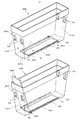
図17は、第5実施形態のメダル補助収納ケース240Eの外観を示しており、図17(a)は、2つのケース底板260Eをケース本体250Eの底面部252に載置して、開口孔242を塞いだ状態のメダル補助収納ケース240Eの外観斜視図であり、図17(b)は、2つのケース底板260Eをケース本体250Eの側面部251Eに立てかけて、開口孔242の一部をメダル排出孔243とした状態のメダル補助収納ケース240Eの外観斜視図であり、図17(c)は、ケース底板260Eをケース本体250Eの側面部251Eに立てかけたときのケース底板260Eの傾斜姿勢を示す側面透視図である。
(Fifth embodiment)
FIG. 17 shows the appearance of the medal auxiliary storage case 240E of the fifth embodiment. FIG. 17A shows two opening holes 242 by placing two case bottom plates 260E on the bottom surface portion 252 of the case body 250E. 17B is an external perspective view of the medal auxiliary storage case 240E in a state where it is closed. FIG. 17B shows two case bottom plates 260E leaning against the side surface portion 251E of the case body 250E, and a part of the opening hole 242 is discharged from the medal. FIG. 17C is an external perspective view of the medal auxiliary storage case 240E in the state of the hole 243, and FIG. 17C is a side view showing an inclined posture of the case bottom plate 260E when the case bottom plate 260E is leaned against the side surface portion 251E of the case main body 250E. FIG.

メダル補助収納ケース240Eは、第4実施形態のメダル補助収納ケース240Dと略同一の構成をしているが、2つのケース底板260Eを備える点、段状係止片256を両短手側面251Ea双方に備えている点が、メダル補助収納ケース240Dと異なっている。   The medal auxiliary storage case 240E has substantially the same configuration as the medal auxiliary storage case 240D of the fourth embodiment. However, the medal auxiliary storage case 240E includes two case bottom plates 260E, and the stepped locking pieces 256 are arranged on both short side surfaces 251Ea. Is different from the medal auxiliary storage case 240D.

すなわち、ケース本体250Eの2つの短手側面251Eaには、高さが異なる複数(本実施形態では3つ)の段差係止片255がそれぞれ突設されており、ケース底板260Eの一端が段状係止片256に係止されるようになっている。   That is, two short side surfaces 251Ea of the case body 250E are provided with a plurality of (three in this embodiment) step locking pieces 255 having different heights, and one end of the case bottom plate 260E is stepped. The locking piece 256 is locked.

また、ケース底板260Eは、第4実施形態のケース底板260Dと略同一の形状であるがその大きさはケース底板260Dの約半分である。すなわち、各ケース底板260Eは、長手側面の一端に支持棒262Eが挿設されているとともに、支持棒262Eの両先端には、抜止部材が突設されているので、2つの支持棒262Eは案内孔25D上を脱抜不可能となっている。   The case bottom plate 260E has substantially the same shape as the case bottom plate 260D of the fourth embodiment, but its size is about half of the case bottom plate 260D. That is, in each case bottom plate 260E, a support bar 262E is inserted at one end of the longitudinal side surface, and a retaining member is provided at both ends of the support bar 262E, so that the two support bars 262E are guided. It is impossible to remove the hole 25D.

メダル補助収納ケース240Eの底面を全閉状態とする場合には、図17(a)に示すように、一方のケース底板260Eの一端に挿通された支持棒262Eを案内孔262Eの略中央P1に位置付けるとともに、ケース底板260Eを開口孔242の前方半分上に載置して、開口孔242の前方半分を塞ぐ。また、他方のケース底板260Eの一端に挿通された支持棒262Eを案内孔262Eの略中央P2に位置付けるとともに、ケース底板260Eを開口孔242の後方半分上に載置して、開口孔242の後方半分を塞ぐ。この結果、ケース底板260Eの開口孔242は塞がれて、メダル補助収納ケース240Eの底面は全閉状態となる。   When the bottom surface of the medal auxiliary storage case 240E is fully closed, as shown in FIG. 17A, the support bar 262E inserted through one end of one case bottom plate 260E is placed at the approximate center P1 of the guide hole 262E. At the same time, the case bottom plate 260E is placed on the front half of the opening hole 242, and the front half of the opening hole 242 is closed. Further, the support bar 262E inserted into one end of the other case bottom plate 260E is positioned at the approximate center P2 of the guide hole 262E, and the case bottom plate 260E is placed on the rear half of the opening hole 242 so that the rear of the opening hole 242 Block half. As a result, the opening hole 242 of the case bottom plate 260E is closed, and the bottom surface of the medal auxiliary storage case 240E is fully closed.

一方、メダル補助収納ケース240Eの底面を開口状態とする場合には、図17(b)に示すように、一方のケース底板260Eの一端に挿通された支持棒262Eを案内孔254Dの中間所定位置P3に位置付けるとともに、ケース底板260Eの他端をケース本体250Eの前方側の短手側面251Ea上に突設された段状係止片256に係止する。また、他方のケース底板260Eの一端に挿通された支持棒262Eを案内孔254Dの中間所定位置P4に位置付けるとともに、ケース底板260Eの他端をケース本体250Eの後方側の短手側面251Ea上に突設された段状係止片256に係止する。この結果、開口孔242の中央一部をメダル排出孔243とすることができる。   On the other hand, when the bottom surface of the medal auxiliary storage case 240E is opened, as shown in FIG. 17 (b), the support rod 262E inserted through one end of the one case bottom plate 260E is inserted into the guide hole 254D at an intermediate predetermined position. While being positioned at P3, the other end of the case bottom plate 260E is locked to a stepped locking piece 256 protruding on the short side surface 251Ea on the front side of the case main body 250E. Further, the support rod 262E inserted into one end of the other case bottom plate 260E is positioned at a predetermined intermediate position P4 of the guide hole 254D, and the other end of the case bottom plate 260E projects on the short side surface 251Ea on the rear side of the case main body 250E. Locks to the provided stepped locking piece 256. As a result, the central part of the opening hole 242 can be a medal discharge hole 243.

本実施形態においては第4実施形態と同様に、2つのケース底板260Eの支持棒262Eが挿設されていない一端をいずれの段状係止片256に係止するかで、図17(c)に示すように、2つのケース底板260Eの傾斜姿勢及びメダル排出孔243の開口位置及び開口面積が決定される。具体的には、2つのケース底板260Eをより高い位置の段状係止片256に係止することで、メダル排出孔243の開口面積はより大きく形成される。   In this embodiment, as in the fourth embodiment, depending on which step-shaped locking piece 256 the one end of the two case bottom plates 260E where the support bar 262E is not inserted is locked, FIG. As shown in FIG. 4, the inclination posture of the two case bottom plates 260E and the opening position and opening area of the medal discharge hole 243 are determined. Specifically, the opening area of the medal discharge hole 243 is formed larger by locking the two case bottom plates 260E to the stepped locking pieces 256 at a higher position.

なお、本実施形態においては、段状係止片256を両短手側面251Ea双方に備えて、2つのケース底板260Eを備えているため、メダル排出孔243の開口位置及び開口面積は、第4実施形態と比べて、より多様性を有するものである。図18に、ケース底板260Eの傾斜姿勢とメダル排出孔243の開口位置を対応させた図を示す。ここで、図18(a)は、2つのケース底板260Eを開口孔242上に載置して、メダル排出孔243を形成しない場合、図18(b)は、一方のケース底板260Eを最上段(下から三段目)に係止し、他方のケース底板260Eを開口孔242上に載置した場合、図18(c)は、一方のケース底板260Eを中段(下から二段目)に係止し、他方のケース底板260Eを最下段(下から一段目)に係止した場合、図18(d)は、2つのケース底板260Eをそれぞれ中段(下から二段目)に係止した場合を示している。   In the present embodiment, since the stepped locking pieces 256 are provided on both the short side surfaces 251Ea and the two case bottom plates 260E are provided, the opening position and the opening area of the medal discharge hole 243 are the same as those in the fourth embodiment. Compared to the embodiment, it has more diversity. FIG. 18 is a diagram in which the inclination posture of the case bottom plate 260E is associated with the opening position of the medal discharge hole 243. Here, in FIG. 18A, when two case bottom plates 260E are placed on the opening holes 242 and the medal discharge holes 243 are not formed, FIG. 18B shows one case bottom plate 260E at the uppermost stage. When the other case bottom plate 260E is placed on the opening hole 242, the case bottom plate 260E is placed in the middle step (second step from the bottom) as shown in FIG. When the other case bottom plate 260E is locked to the lowest level (first level from the bottom), FIG. 18D shows that the two case bottom plates 260E are locked to the middle level (second level from the bottom). Shows the case.

このように本実施形態においては、ケース本体250Eの2つのケース底板260Eの配設位置に応じて、開口位置及び開口面積が異なる複数のメダル排出孔243を形成することができる。   Thus, in the present embodiment, a plurality of medal discharge holes 243 having different opening positions and opening areas can be formed according to the arrangement positions of the two case bottom plates 260E of the case main body 250E.

また、本実施形態においては、2つのケース底板260Eの支持棒262Eは、直線状の案内孔252E上を移動可能となっているが、ケース本体250Eから脱抜不可能に構成しているので、2つのケース底板260Eを移動させて多様なメダル排出孔243を形成しつつも、ケース底板260Eを紛失することがない。   In the present embodiment, the support bars 262E of the two case bottom plates 260E are movable on the linear guide holes 252E, but are configured so as not to be removed from the case body 250E. While the two case bottom plates 260E are moved to form various medal discharge holes 243, the case bottom plate 260E is not lost.

さらには、本実施形態においては、上記実施形態では露出していたケース本体の底面部における長手方向端部が、2つのケース底板260Eによって遮蔽されているので、メダル補助収納ケース240Eに落ちてくるメダルは確実にメダル排出孔243に案内され、メダル自動回収装置900に回収されるようになっている。すなわち、上記実施形態では、ケース本体の底面部の長手方向一端(ケース底板が係止されていない側)には、メダルが貯留してしまう可能性があったが、本実施形態においては、ケース本体の底面部の長手方向の両端には、2つのケース底板260Eが存在し、かつ、2つのケース底板260Eが傾斜配設されているので、メダル補助収納ケース240Eに収容されるメダルは確実にメダル排出孔243に案内されるようになっている。   Furthermore, in the present embodiment, the longitudinal end portion of the bottom surface of the case body that was exposed in the above embodiment is shielded by the two case bottom plates 260E, and thus falls into the medal auxiliary storage case 240E. The medal is surely guided to the medal discharge hole 243 and collected by the medal automatic collecting device 900. That is, in the above embodiment, there is a possibility that medals may be stored at one end in the longitudinal direction of the bottom surface of the case body (the side where the case bottom plate is not locked). Two case bottom plates 260E exist at both ends in the longitudinal direction of the bottom surface of the main body, and the two case bottom plates 260E are inclined, so that medals stored in the medal auxiliary storage case 240E are surely The medal discharge hole 243 is guided.

以上、本発明の実施の形態について説明してきたが、本発明は、上述した実施の形態に限られるものではなく、本発明の要旨を逸脱しない範囲において、本発明の実施の形態に対して種々の変形や変更を施すことができ、そのような変形や変更を伴うものもまた、本発明の技術的範囲に含まれるものである。また、発明の実施の形態に記載された、作用及び効果は、本発明から生じる最も好適な作用及び効果を列挙したに過ぎず、本発明による作用及び効果は、本発明の実施の形態に記載されたものに限定されるものではない。   Although the embodiments of the present invention have been described above, the present invention is not limited to the above-described embodiments, and various modifications can be made to the embodiments of the present invention without departing from the gist of the present invention. Such modifications and changes can be made, and those accompanying such modifications and changes are also included in the technical scope of the present invention. Further, the actions and effects described in the embodiments of the invention only list the most preferable actions and effects resulting from the present invention, and the actions and effects according to the present invention are described in the embodiments of the present invention. It is not limited to what was done.

本発明の一実施形態に係るスロットマシンの外観を示す斜視図である。It is a perspective view showing the appearance of the slot machine according to one embodiment of the present invention. 本発明の一実施形態に係るスロットマシンの前面扉を開放した状態の斜視図である。It is a perspective view of the state which opened the front door of the slot machine concerning one embodiment of the present invention. (a)は、本発明の一実施形態に係るスロットマシンのメダル払出装置の外観斜視図、(b)は、メダル払出装置の一部を欠截した断面斜視図である。(A) is an external perspective view of the medal payout device of the slot machine according to the embodiment of the present invention, and (b) is a cross-sectional perspective view in which a part of the medal payout device is omitted. 本発明の一実施形態に係るスロットマシンの内部に配設されたメダル払出装置及びメダル補助収納ケースを右側から見たときの側面図である。It is a side view when the medal payout device and the medal auxiliary storage case disposed in the slot machine according to the embodiment of the present invention are viewed from the right side. 本発明の一実施形態に係るスロットマシンのメダル補助収納ケースの外観斜視図である。It is an external appearance perspective view of the medal auxiliary storage case of the slot machine according to one embodiment of the present invention. (a)は、本発明の一実施形態に係るスロットマシンのメダル補助収納ケースを本体に設置した状態の外観斜視図、(b)は、メダル補助収納ケースを本体から取り外した状態の外観斜視図である。(A) is an external perspective view of the slot machine according to one embodiment of the present invention with the medal auxiliary storage case installed on the main body, and (b) is an external perspective view of the slot machine with the medal auxiliary storage case removed from the main body. It is. 本発明の一実施形態に係るスロットマシンのメダル補助収納ケース及び本体底板の開口位置とメダル自動回収装置の回収口との位置関係を示す側面図であり、(a)は、前方位置にメダル自動回収装置の回収口が配設される場合、(b)は、後方位置にメダル自動回収装置の回収口が配設される場合を示している。It is a side view which shows the positional relationship of the medal auxiliary storage case of the slot machine which concerns on one Embodiment of this invention, the opening position of a main body bottom plate, and the collection port of an automatic medal recovery apparatus, (a) is automatic medal at a front position. When the collection port of the collection device is arranged, (b) shows the case where the collection port of the automatic medal collection device is arranged at the rear position. 本発明の一実施形態に係るスロットマシンのメダル補助収納ケースのケース底板の外観図であり(a)は、ケース底板の外観斜視図、側面図、及び下面図であり、(b)は、ケース底板の支持棒の分解斜視図である。FIG. 4A is an external perspective view, a side view, and a bottom view of the case bottom plate of the medal auxiliary storage case of the medal auxiliary storage case of the slot machine according to the embodiment of the present invention, and FIG. It is a disassembled perspective view of the support bar of a bottom plate. 本発明の一実施形態に係るスロットマシンのメダル補助収納ケースのケース底板が底面にメダル排出孔を形成している状態を示す図であり、図9(a)は、後方底面にメダル排出孔を形成している状態のメダル補助収納ケース240の外観斜視図、図9(b)は、前方底面及び後方底面にメダル排出孔を形成したときのケース底板のそれぞれの位置を示す側面図及びメダル排出孔の位置を示す上面図である。FIG. 9A is a view showing a state in which the case bottom plate of the medal auxiliary storage case of the slot machine according to the embodiment of the present invention forms a medal discharge hole on the bottom surface, and FIG. FIG. 9B is a side view showing the respective positions of the case bottom plate when the medal discharge holes are formed in the front bottom surface and the rear bottom surface, and the medal discharge. It is a top view which shows the position of a hole. 本発明の一実施形態に係るスロットマシンのメダル補助収納ケースの変形例において、ケース底板が底面にメダル排出孔を形成している状態を示す図である。In the modification of the medal auxiliary storage case of the slot machine according to the embodiment of the present invention, the case bottom plate shows a state where the medal discharge hole is formed on the bottom surface. 本発明の一実施形態に係るスロットマシンの主制御部の回路構成を示すブロック図である。FIG. 4 is a block diagram showing a circuit configuration of a main control unit of the slot machine according to the embodiment of the present invention. 本発明の一実施形態に係るスロットマシンの副制御部の回路構成を示すブロック図である。FIG. 4 is a block diagram showing a circuit configuration of a sub control unit of the slot machine according to the embodiment of the present invention. 本発明の一実施形態に係るスロットマシンの主制御部メイン処理を示すフローチャートである。10 is a flowchart showing main processing of the main control unit of the slot machine according to the embodiment of the present invention. 本発明の別の実施形態(第2実施形態)に係るメダル補助収納ケースの外観を示す図であり、(a)は、メダル補助収納ケースの外観斜視図、(b)は、メダル補助収納ケースの側面図及び下面図である。It is a figure which shows the external appearance of the medal auxiliary storage case which concerns on another embodiment (2nd Embodiment) of this invention, (a) is an external appearance perspective view of a medal auxiliary storage case, (b) is a medal auxiliary storage case. It is the side view and bottom view of this. 本発明の別の実施形態(第3実施形態)に係るメダル補助収納ケースの外観を示す図であり、(a)は、ケース底板をケース本体の底面部に載置して、開口孔を塞いだ状態のメダル補助収納ケースの外観斜視図であり、(b)は、ケース底板をケース本体の側面部に立てかけて、開口孔を全開にして、メダル排出孔を形成した状態のメダル補助収納ケースの外観斜視図である。It is a figure which shows the external appearance of the medal auxiliary storage case which concerns on another embodiment (3rd Embodiment) of this invention, (a) mounts a case bottom plate in the bottom face part of a case main body, and plugs up an opening hole. FIG. 5B is an external perspective view of the medal auxiliary storage case in a state where the medal auxiliary storage case is in a state where the case bottom plate is leaned against the side surface of the case body, the opening hole is fully opened, and the medal discharge hole is formed. FIG. 本発明の別の実施形態(第4実施形態)に係るメダル補助収納ケースの外観を示す図であり、(a)は、ケース底板をケース本体の底面部に載置して、開口孔を塞いだ状態のメダル補助収納ケースの外観斜視図であり、(b)は、ケース底板をケース本体の側面部に立てかけて、開口孔の一部をメダル排出孔とした状態のメダル補助収納ケースの外観斜視図であり、(c)は、ケース底板をケース本体の側面部に立てかけたときのケース底板の傾斜姿勢を示す側面透視図である。It is a figure which shows the external appearance of the medal auxiliary storage case which concerns on another embodiment (4th Embodiment) of this invention, (a) mounts a case bottom plate in the bottom face part of a case main body, and plugs up an opening hole. FIG. 6B is an external perspective view of the medal auxiliary storage case in an open state, and FIG. 6B is an external view of the medal auxiliary storage case in a state where the case bottom plate is leaned against the side surface of the case body and a part of the opening hole is a medal discharge hole. It is a perspective view, (c) is a side perspective view showing the inclined posture of the case bottom plate when the case bottom plate is leaned against the side surface portion of the case body. 本発明の別の実施形態(第5実施形態)に係るメダル補助収納ケースの外観を示す図であり、(a)は、2つのケース底板をケース本体の底面部に載置して、開口孔を塞いだ状態のメダル補助収納ケースの外観斜視図であり、(b)は、2つのケース底板をケース本体の側面部に立てかけて、開口孔の一部をメダル排出孔とした状態のメダル補助収納ケースの外観斜視図であり、(c)は、ケース底板をケース本体の側面部に立てかけたときのケース底板の傾斜姿勢を示す側面透視図である。It is a figure which shows the external appearance of the medal auxiliary storage case which concerns on another embodiment (5th Embodiment) of this invention, (a) mounts two case bottom plates in the bottom face part of a case main body, FIG. 7B is an external perspective view of the medal auxiliary storage case in a state where the case is closed, and FIG. 6B is a medal auxiliary in a state where two case bottom plates are leaned against the side surface of the case body and a part of the opening hole is used as a medal discharge hole. It is an external appearance perspective view of a storage case, (c) is a side perspective view which shows the inclination attitude | position of a case bottom board when a case bottom board is leaned on the side part of the case main body. 本発明の別の実施形態(第5実施形態)に係るメダル補助収納ケースにおいて、ケース底板の傾斜姿勢とメダル排出孔の開口位置を対応させた図である。In the medal auxiliary storage case according to another embodiment (fifth embodiment) of the present invention, the inclination posture of the case bottom plate and the opening position of the medal discharge hole are made to correspond to each other.

Claims (5)

メダルタンクに貯蔵されたメダルを排出するメダル払出装置と、前記メダルタンクから溢れたメダルを収納するメダル補助収納ケースと、を備え、
前記メダル補助収納ケースは、
上部及び底部を開口させた箱体のケース本体と、前記ケース本体の底部の開口を閉じるケース底板と、を備え、
メダル自動回収装置に接続される場合には、前記ケース底板を移動させて前記ケース本体の底部の開口をメダル排出口とすることで前記メダル補助収納ケースをメダルの排出用途とし、前記メダル補助収納ケースが載置される載置板には、前記メダル自動回収装置が接続された位置に対応する位置に開口を形成し、前記メダル排出口および前記載置板の開口を経由して前記メダル自動回収装置にメダルを排出する遊技台であって、
前記ケース底板は、
前記ケース本体に係止される底板係止部を備え、
前記ケース本体は、
係止された底板係止部を支持する本体支持部を備え、
前記本体支持部は、
前記底板係止部を、前記ケース底板が前記底部の開口の全てを閉じる第1の位置と、ケース底板が前記底部の開口の一部を閉じる複数の第2の位置との間で移動可能、かつ、取り外し困難に支持し、
前記複数の第2の位置それぞれにおいては、
前記底部の開口位置が異なる前記メダル排出孔が形成されることを特徴とする遊技台。
A medal payout device for discharging medals stored in the medal tank; and a medal auxiliary storage case for storing medals overflowing from the medal tank;
The medal auxiliary storage case is
A case body of a box body having an upper portion and a bottom portion opened, and a case bottom plate for closing an opening of the bottom portion of the case body,
When connected to an automatic medal collection device, the medal auxiliary storage case is used for medal discharge by moving the case bottom plate and using the opening at the bottom of the case body as a medal discharge port, and the medal auxiliary storage An opening is formed in the mounting plate on which the case is mounted at a position corresponding to the position where the automatic medal recovery device is connected, and the automatic medal is passed through the medal discharge port and the opening of the mounting plate. A game stand for discharging medals to a collecting device,
The case bottom plate is
A bottom plate locking portion locked to the case body,
The case body is
A main body support portion that supports the locked bottom plate locking portion,
The main body support is
The bottom plate locking portion is movable between a first position where the case bottom plate closes all of the bottom opening and a plurality of second positions where the case bottom plate closes a part of the bottom opening. And support it difficult to remove,
In each of the plurality of second positions,
The game table, wherein the medal discharge holes having different opening positions at the bottom are formed.
前記本体支持部は、
前記第1の位置から前記第2の位置まで連通する案内孔として、前記ケース本体の両長手側面上の対向する位置にそれぞれ形成され、
前記底板係止部は、
前記ケース底板の両側面から突出して、対向する前記案内孔上を移動可能であるとともに、対向する前記案内孔に係止可能な支持部材と、
前記ケース本体の外側に突出した前記支持部材の両先端に、前記案内孔の幅より大きな外形寸法を有する抜止部材と、
を備え、
前記ケース底板は、
前記支持部材を支軸として姿勢を変化可能とすることを特徴とする請求項1記載の遊技台。
The main body support is
As guide holes communicating from the first position to the second position, formed at opposing positions on both longitudinal side surfaces of the case body,
The bottom plate locking portion is
A support member that protrudes from both side surfaces of the case bottom plate and is movable on the opposing guide holes and is latchable in the opposing guide holes;
A retaining member having an outer dimension larger than the width of the guide hole at both ends of the support member protruding outside the case body;
With
The case bottom plate is
The game table according to claim 1, wherein the posture can be changed with the support member as a support shaft.
前記ケース底板は、
前記底板係止部が前記第2の位置にある場合には、前記ケース本体に傾斜して支持され、前記底部に形成されたメダル排出孔にメダルを案内誘導することを特徴とする請求項2記載の遊技台。
The case bottom plate is
3. The medal is guided and guided to a medal discharge hole formed in the bottom portion, supported by being inclined to the case body when the bottom plate locking portion is in the second position. The listed game table.
前記ケース底板は、
その長手端部に前記ケース本体の短手側面に係止する係止突部を備えることを特徴とする請求項2又は3記載の遊技台。
The case bottom plate is
4. The game table according to claim 2, further comprising a locking projection that is locked to a short side surface of the case main body at a longitudinal end thereof.
前記底板係止部が前記第2の位置にあるときに形成される複数のメダル排出孔は、それぞれ、前記底部の開口位置は異なるが、開口面積は同一であることを特徴とする請求項1乃至4のいずれか1項に記載の遊技台。   The plurality of medal discharge holes formed when the bottom plate locking portion is in the second position are different in opening position of the bottom portion, but have the same opening area. 5. The game table according to any one of items 4 to 4.
JP2008240181A 2008-09-19 2008-09-19 Amusement stand Expired - Fee Related JP4976355B2 (en)

Priority Applications (1)

Application Number Priority Date Filing Date Title
JP2008240181A JP4976355B2 (en) 2008-09-19 2008-09-19 Amusement stand

Applications Claiming Priority (1)

Application Number Priority Date Filing Date Title
JP2008240181A JP4976355B2 (en) 2008-09-19 2008-09-19 Amusement stand

Publications (2)

Publication Number Publication Date
JP2010069028A true JP2010069028A (en) 2010-04-02
JP4976355B2 JP4976355B2 (en) 2012-07-18

Family

ID=42201359

Family Applications (1)

Application Number Title Priority Date Filing Date
JP2008240181A Expired - Fee Related JP4976355B2 (en) 2008-09-19 2008-09-19 Amusement stand

Country Status (1)

Country Link
JP (1) JP4976355B2 (en)

Cited By (3)

* Cited by examiner, † Cited by third party
Publication number Priority date Publication date Assignee Title
JP2014104025A (en) * 2012-11-26 2014-06-09 Olympia:Kk Game machine
JP2016503200A (en) * 2012-12-14 2016-02-01 ノヴォマティック アクツィエンゲゼルシャフトNovomatic Ag Coin box for coin insertion device
JP2020062277A (en) * 2018-10-18 2020-04-23 株式会社北電子 Game machine

Citations (6)

* Cited by examiner, † Cited by third party
Publication number Priority date Publication date Assignee Title
JP2003205069A (en) * 2002-01-17 2003-07-22 Sanyo Product Co Ltd Game machine
JP2005040572A (en) * 2003-10-29 2005-02-17 Oizumi Corp Recovery tank for game machine
JP2005177178A (en) * 2003-12-19 2005-07-07 Samii Kk Game machine
JP2005177177A (en) * 2003-12-19 2005-07-07 Samii Kk Game machine
JP2007061387A (en) * 2005-08-31 2007-03-15 Yoos Inter Japan Kk Bottom member of token collecting box, and token collecting box
JP2008011909A (en) * 2006-07-03 2008-01-24 Olympia:Kk Game medium-receiving box and game machine

Patent Citations (6)

* Cited by examiner, † Cited by third party
Publication number Priority date Publication date Assignee Title
JP2003205069A (en) * 2002-01-17 2003-07-22 Sanyo Product Co Ltd Game machine
JP2005040572A (en) * 2003-10-29 2005-02-17 Oizumi Corp Recovery tank for game machine
JP2005177178A (en) * 2003-12-19 2005-07-07 Samii Kk Game machine
JP2005177177A (en) * 2003-12-19 2005-07-07 Samii Kk Game machine
JP2007061387A (en) * 2005-08-31 2007-03-15 Yoos Inter Japan Kk Bottom member of token collecting box, and token collecting box
JP2008011909A (en) * 2006-07-03 2008-01-24 Olympia:Kk Game medium-receiving box and game machine

Cited By (4)

* Cited by examiner, † Cited by third party
Publication number Priority date Publication date Assignee Title
JP2014104025A (en) * 2012-11-26 2014-06-09 Olympia:Kk Game machine
JP2016503200A (en) * 2012-12-14 2016-02-01 ノヴォマティック アクツィエンゲゼルシャフトNovomatic Ag Coin box for coin insertion device
JP2020062277A (en) * 2018-10-18 2020-04-23 株式会社北電子 Game machine
JP7127824B2 (en) 2018-10-18 2022-08-30 株式会社北電子 game machine

Also Published As

Publication number Publication date
JP4976355B2 (en) 2012-07-18

Similar Documents

Publication Publication Date Title
JP4909314B2 (en) Game table and IC cover member for game table
JP4830522B2 (en) Game machine
JP6667891B1 (en) Gaming machine
JP4892495B2 (en) Game table and game medium payout device
JP4976355B2 (en) Amusement stand
JP4608469B2 (en) Amusement stand
JP2003310832A (en) Slot machine
JP2010094232A (en) Game table
JP2003310835A (en) Slot machine
JP4929266B2 (en) Amusement stand
JP2008246031A (en) Token selector and game machine provided with token selector
JP6667892B1 (en) Gaming machine
JP2003310837A (en) Slot machine
JP6667890B1 (en) Gaming machine
JP5145546B2 (en) Amusement stand
JP2009131390A (en) Game machine
JP4920635B2 (en) Locking device unit and game table using the same
JP2009279084A (en) Fixing pin for game table
JP5344397B2 (en) Amusement stand
JP2009195377A (en) Board-housing case for game table, and game table
JP4822425B2 (en) GAME MACHINE AND GAME MEDIUM DISCHARGE DEVICE LOCK MECHANISM
JP2008054729A (en) Game machine
JP2008054737A (en) Game machine
JP4751760B2 (en) Coin dispensing device
JP4800446B2 (en) Amusement stand

Legal Events

Date Code Title Description
A621 Written request for application examination

Free format text: JAPANESE INTERMEDIATE CODE: A621

Effective date: 20100224

A977 Report on retrieval

Free format text: JAPANESE INTERMEDIATE CODE: A971007

Effective date: 20120328

TRDD Decision of grant or rejection written
A01 Written decision to grant a patent or to grant a registration (utility model)

Free format text: JAPANESE INTERMEDIATE CODE: A01

Effective date: 20120403

A01 Written decision to grant a patent or to grant a registration (utility model)

Free format text: JAPANESE INTERMEDIATE CODE: A01

A61 First payment of annual fees (during grant procedure)

Free format text: JAPANESE INTERMEDIATE CODE: A61

Effective date: 20120412

R150 Certificate of patent or registration of utility model

Free format text: JAPANESE INTERMEDIATE CODE: R150

FPAY Renewal fee payment (event date is renewal date of database)

Free format text: PAYMENT UNTIL: 20150420

Year of fee payment: 3

R250 Receipt of annual fees

Free format text: JAPANESE INTERMEDIATE CODE: R250

LAPS Cancellation because of no payment of annual fees