JP2010068802A - Motor-driven pruning scissors - Google Patents
Motor-driven pruning scissors Download PDFInfo
- Publication number
- JP2010068802A JP2010068802A JP2009201322A JP2009201322A JP2010068802A JP 2010068802 A JP2010068802 A JP 2010068802A JP 2009201322 A JP2009201322 A JP 2009201322A JP 2009201322 A JP2009201322 A JP 2009201322A JP 2010068802 A JP2010068802 A JP 2010068802A
- Authority
- JP
- Japan
- Prior art keywords
- motor
- blade
- switch
- contact
- operating
- Prior art date
- Legal status (The legal status is an assumption and is not a legal conclusion. Google has not performed a legal analysis and makes no representation as to the accuracy of the status listed.)
- Granted
Links
Images


Classifications
-
- B—PERFORMING OPERATIONS; TRANSPORTING
- B26—HAND CUTTING TOOLS; CUTTING; SEVERING
- B26B—HAND-HELD CUTTING TOOLS NOT OTHERWISE PROVIDED FOR
- B26B15/00—Hand-held shears with motor-driven blades
-
- A—HUMAN NECESSITIES
- A01—AGRICULTURE; FORESTRY; ANIMAL HUSBANDRY; HUNTING; TRAPPING; FISHING
- A01G—HORTICULTURE; CULTIVATION OF VEGETABLES, FLOWERS, RICE, FRUIT, VINES, HOPS OR SEAWEED; FORESTRY; WATERING
- A01G3/00—Cutting implements specially adapted for horticultural purposes; Delimbing standing trees
- A01G3/02—Secateurs; Flower or fruit shears
- A01G3/033—Secateurs; Flower or fruit shears having motor-driven blades
- A01G3/037—Secateurs; Flower or fruit shears having motor-driven blades the driving means being an electric motor
-
- B—PERFORMING OPERATIONS; TRANSPORTING
- B26—HAND CUTTING TOOLS; CUTTING; SEVERING
- B26D—CUTTING; DETAILS COMMON TO MACHINES FOR PERFORATING, PUNCHING, CUTTING-OUT, STAMPING-OUT OR SEVERING
- B26D5/00—Arrangements for operating and controlling machines or devices for cutting, cutting-out, stamping-out, punching, perforating, or severing by means other than cutting
- B26D5/08—Means for actuating the cutting member to effect the cut
Abstract
Description
本発明は、電動式剪定バサミに関し、更に詳しくは、果樹木の剪定作業時に作業速度を高めることができ、手の疲労感をなくすることができるなど作業の便利性を図ることができる電動式剪定バサミに関する。 The present invention relates to an electric pruning shears, and more specifically, an electric type that can increase work speed during pruning work of fruit trees and can eliminate the feeling of hand fatigue and can improve work convenience. About pruning shears.
一般的に、果樹、造景、山林及び花卉用各種作物や樹木の枝打ちのためには剪定バサミ、剪定ノコギリまたは刀などを利用する。 In general, pruning shears, pruning saws, or swords are used for fruit trees, landscapes, various forest and flower crops and tree pruning.
通常、剪定バサミは単純に作業者の人力だけに依存するため、多くの作業時間が所要され、作業能力も非常に落ちる。
これを解決するために、モータの駆動力を基盤として作動する電動式剪定バサミに関する機器が多く出仕されている。
このような電動式剪定バサミの刃は、本体に固定された固定刃と稼動刃とで構成され、稼動刃が固定刃上に形成された回転軸を中心として一定区間を反復して動くことで、固定刃と共に剪定作業を行う。
前記稼動刃の反復運動は、モータの回転力により条件なく反復的に行われる。
Usually, since the pruning shears are simply dependent on the operator's human power, a lot of work time is required and the work ability is greatly reduced.
In order to solve this, many devices related to the electric pruning shears that operate on the basis of the driving force of the motor are available.
The blade of such an electric pruning scissors is composed of a fixed blade and an operating blade fixed to the main body, and the operating blade moves repeatedly in a certain section around a rotation axis formed on the fixed blade. Pruning work with fixed blade.
The repetitive movement of the working blade is repeatedly performed without condition by the rotational force of the motor.
最近では、1回の充電で一定時間連続して使用が可能であり、取り扱いが簡単な携帯用電動式剪定バサミに対する選好度が高くなっているなど、次第に小型化と軽量化を追及するようになってきている。 Recently, it is possible to use continuously for a certain time with one charge, and the preference for portable electric pruning scissors that are easy to handle has increased, so that the miniaturization and weight reduction are gradually pursued. It has become to.
最近の電動式剪定バサミの場合、機能性はもちろん安定性にも重点を置いているが、これにより作動スイッチ以外にも取り扱い時の安全を図るために、別途の安全スイッチを具備しているなど部品追加によってサイズと重量が増加し、結局機器の軽量化及び小型化に不利である。 In the case of the recent electric pruning shears, emphasis is placed on stability as well as functionality, but in addition to the operation switch, a separate safety switch is provided to ensure safety during handling. Adding parts increases the size and weight, which is disadvantageous for reducing the weight and size of the equipment.
更に、従来の電動式剪定バサミを使用する場合、特にモータの可用な負荷以上の駆動力が要求される枝を切断しようとする場合は、剪定バサミの刃が枝を切断できない場合がある。
この場合、剪定バサミの刃が枝に挟まってしまい、挟まり続けることもあり得る。
このようになると、これ以上の剪定作業が不可能となり得る。
このような状態でモータは継続過負荷状態に置かれるため、モータだけでなく他の部品までも損傷を受ける。
Furthermore, when using a conventional electric pruning scissors, the blade of the pruning scissors may not be able to cut the branches, particularly when trying to cut a branch that requires a driving force greater than the available load of the motor.
In this case, the pruning scissors blade may be pinched by the branches and may continue to be pinched.
When this happens, no further pruning work may be possible.
In this state, since the motor is placed in a continuous overload state, not only the motor but also other parts are damaged.
このような状況を防止するためにヒューズを使用することもできるが、このような方法が使用者の不便まで除去するわけではない。 Although fuses can be used to prevent this situation, such methods do not eliminate the user's inconvenience.
本発明は前記のような点を勘案して案出したものであり、本発明の目的は、本体から分離して指に挟んで使用することができる別途の安全スイッチを備えた新しい形態のスイッチ手段を具現する電動式剪定バサミを提供することにある。 The present invention has been devised in view of the above points, and an object of the present invention is to provide a new type switch having a separate safety switch that can be used by being sandwiched between fingers by separating from the main body. An object of the present invention is to provide an electric pruning scissors that embodies the means.
更に、本発明の別の目的は、剪定作業中の刃が電源の供給にもかかわらず、剪定作業のためのハサミに異常が生じた場合、モータが逆回転するように制御することで、モータの損傷を含む全般的な異常状態を脱することができる電動式剪定バサミを提供することにある。 Furthermore, another object of the present invention is to control the motor so that the motor rotates in the reverse direction when an abnormality occurs in the scissors for the pruning operation despite the supply of power to the blade during the pruning operation. It is an object of the present invention to provide an electric pruning scissors that can escape from general abnormal states including damages.
前記目的を達成するために、本発明は、固定刃と稼動刃とを具備して、モータの駆動力にて稼動刃を作動させることで剪定作業を行う電動式剪定バサミにおいて、
前記モータの作動のために本体の片側に設置される稼動接点及び固定接点とで構成される接点スイッチと、指に挟むことができる別途の輪形態からなり、磁石を内装して磁力で接点スイッチの稼動接点と固定接点を引っ付けることで、モータを作動させることができる携帯用作動スイッチと、を更に含む電動式剪定バサミを特徴とする。
In order to achieve the above object, the present invention comprises an electric pruning shears comprising a fixed blade and a working blade, and performing a pruning operation by operating the working blade with a driving force of a motor.
It consists of a contact switch composed of an operating contact and a fixed contact installed on one side of the main body for the operation of the motor, and a separate ring shape that can be sandwiched between fingers, and has a magnet and a magnetic contact switch The electric pruning scissors further includes a portable operation switch that can operate the motor by pulling the operation contact and the fixed contact.
本発明の電動式剪定バサミによると、モータの強力な駆動力を切断する方式であるため、梨の木、リンゴの木はもちろん、木質が固いミカンの木、オレンジの木など全ての果樹の剪定作業に卓越した性能を示すことはもちろん、特に機器の作動のためのスイッチを指に挟んで使用することができる別途の部品形態で構成することで、安全性を確保することができ、何よりも別途のスイッチ採用によって機器本体のサイズを減らすことができるなど、小型化及び軽量化を図ることができる。 According to the electric pruning shears of the present invention, it is a system that cuts the powerful driving force of the motor, so it is suitable for pruning all fruit trees such as pear trees and apple trees, as well as hard fruit mandarin trees and orange trees. In addition to exhibiting excellent performance, it is possible to ensure safety by configuring it with a separate component form that can be used with the switch for operating the device sandwiched between fingers. By adopting the switch, the size of the device body can be reduced, and the size and weight can be reduced.
このように電動式剪定バサミの小型化及び軽量化によって、軽く手の疲労が全くないため、作業の便利性を図ることができる効果がある。 Since the electric pruning shears are thus reduced in size and weight, there is no hand fatigue and there is an effect that the convenience of work can be improved.
更に、剪定作業中に発生するモータ過負荷状態などの異常を解決することで、モータの破損及び故障などを防止することができるなど機器の耐久寿命を延長することができる長所がある。 Furthermore, by solving an abnormality such as a motor overload state that occurs during the pruning operation, there is an advantage that the durable life of the device can be extended, such as motor breakage and failure can be prevented.
また、電動式剪定バサミの本体下端に磁石が内装された回転リングを設置し、回転リングの回転操作によって剪定作業時にはバッテリーの電源をモータに供給し、剪定バサミを使用しない場合は、電源供給部でバッテリーの電源を遮断することで、ケーブル及び機器本体に電気が入らないようにして、不必要な電力消耗を防止することができる。 Also, a rotating ring with magnets is installed at the bottom of the main body of the electric pruning shears, and the battery power is supplied to the motor during the pruning operation by rotating the rotating ring. When the pruning shears are not used, the power supply unit By shutting off the battery power, unnecessary power consumption can be prevented by preventing electricity from entering the cable and the device main body.
更に、ホールセンサを通して稼動刃の作動状態を感知して接点スイッチに携帯用作動スイッチを一度付けてからはずす時、1度だけで往復移動させ、保管時に一定時間持続的に携帯用作動スイッチを付ける場合、稼動刃が閉状態となるようにすることで、作業の便利性を図ることができる。 Furthermore, when the operating state of the operating blade is sensed through the hall sensor and the portable operating switch is attached to the contact switch and then removed, it is moved back and forth once, and the portable operating switch is continuously attached for a certain time during storage. In this case, the convenience of work can be achieved by making the operating blades in the closed state.
また、既存に機器本体と別途に構成されていたコントロールバックスを本体内部に装着することで、全体的な機器のサイズを減らすことができるため、運搬及び取り扱いが容易である。 Moreover, since the overall size of the device can be reduced by mounting the control bucks, which are separately configured separately from the device main body, inside the main body, it is easy to transport and handle.
以下、本発明の好ましい実施例を添付図面を参照に詳細に説明する。 Hereinafter, preferred embodiments of the present invention will be described in detail with reference to the accompanying drawings.
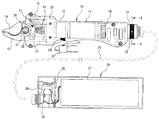
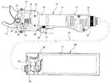
図1は本発明の一実施例による電動式剪定バサミの閉状態を示す図面であり、図2は図1において剪定バサミの開状態を示す図面である。 FIG. 1 is a view showing a closed state of an electric pruning shear according to an embodiment of the present invention, and FIG. 2 is a view showing an opened state of the pruning shear in FIG.
前記電動式剪定バサミは、モータ11及び減速器12とで構成された駆動手段、実質的に剪定作業を行う固定刃13及び稼動刃14、モータ11の作動制御などを担当する制御部19及び電源供給部26、モータ11を作動させるために、オン/オフなどの操作のための携帯用作動スイッチ20などを含む。
The electric pruning shears include a driving means composed of a
前記駆動手段は、モータ11及び減速器12とのギア組み合わせにより生成した駆動力で稼動刃14を動かす役割をし、前記固定刃13と稼動刃14は共に一対をなしながら、剪定作業を行う。
The drive means plays a role of moving the
前記制御部19及び電源供給部26はモータ11などを作動させるための電源を供給し、モータ11が正回転および逆回転機能を行うように、駆動手段に供給される電源を制御する。
The
前記制御部19及び電源供給部26が供給する電源は、充電可能なバッテリー27、または外部の電源を利用することができる。
As the power supplied from the
更に、制御部19及び電源供給部26は、剪定作業時の異常可否を判断して駆動手段のモータ11などを含む全般的な剪定バサミの異常状態を脱するように、駆動手段に供給される電源の相を変えることで、稼動刃14が逆に作動するように制御する。
Further, the
これによって、電動式剪定バサミは剪定作業の遂行中に発生する過負荷などの異常状態を自ら検出し、検出結果、過負荷状態と判断される場合、進行中の剪定作業を中断し、モータ11の逆回転駆動を通して稼動刃14を逆に作動させることで、内部モータ11及び電気回路部分の破損などを防止することができる。
As a result, the electric pruning shears themselves detect an abnormal state such as an overload that occurs during the pruning operation, and if it is determined that the detection result is an overload state, the pruning operation in progress is interrupted, and the
特に、前記携帯用作動スイッチ20の場合には、電動式剪定バサミ本体10とは別途の部品で構成され、使用時のみに指などに挟んで使用することができるようになっている。
In particular, in the case of the
例えば、携帯用作動スイッチ20を指に挟んだ状態で本体10に内装された接点スイッチに当てることで、接点スイッチ33のオン作動によってモータ11を駆動させることができる。
For example, the
これは、以前の安全スイッチ及びこれとかかる周辺部品を本体10から削除することができることを意味し、その結果、電動式剪定バサミの全体的なサイズ及び重量を大幅に減らすことができるという利点を得ることができる。
This means that the previous safety switch and its peripheral components can be removed from the
このような電動式剪定バサミの構造を更に詳しく説明すると次の通りである。 The structure of the electric pruning shears will be described in more detail as follows.
前記電動式剪定バサミの本体10には互いに直結されているモータ11と減速器12が内装設置され、このときのモータ11は本体10の片側に設置されている接点スイッチ33のオン/オフ作動によって電源の供給を受けたり、遮断しながら、駆動または停止される。
A
ここで、前記モータ11は、正/逆回転が可能なモータ11であり、接点スイッチ33のオン時に正方向回転と逆方向回転を反復し、これによって稼動刃14も開と閉を反復しながら剪定作業を行う。
Here, the
前記本体10の上端部は、稼動刃14と固定刃13が広がるように、後述する稼動刃14のギア部16と固定刃13の脚部を包み、本体10の上端内部には長方形形態の支持ブロック22が設置される。このとき、前記支持ブロック22により固定刃13の脚部が支持され、稼動刃14を駆動させるための駆動ギア15の軸部が支持ブロック22により支持される。
The upper end portion of the
即ち、前記駆動ギア15は支持ブロック22の内部で多数のベアリングによる支持を受けながら、回転できるように支持され、このように支持される駆動ギア15の軸部が減速器12の軸と連結されることで、モータ11に発生した回転力が減速器12を通して伝達される。
That is, the
実質的に、剪定作業を行う固定刃13と稼動刃14は支持ブロック22の上端部に支持される構造で設置される。
The fixed
例えば、前記固定刃13の両側脚部分が支持ブロック22の上端部に締結設置されて、支持ブロック22が支持体としての役割をし、このように設置される固定刃13の一面に稼動刃14が互いの刃を向かい合う状態でヒンジピン38により固定される。
For example, both leg portions of the fixed
これによって、稼動刃14がヒンジピン38を中心軸として回転しながら固定刃13との対をなして、剪定作業を行うことができる。
Thus, the pruning operation can be performed while the working
このような稼動刃14の動きのために、稼動刃14の後端部の一面にはギアが成形された扇形のギア部16が一体に形成され、このときのギア部16がモータ11及び減速器12側の駆動ギア15とかみ合うことで、駆動ギア15とのギア伝動により稼動刃14が回転される。
Due to the movement of the working
図3は図1において接点スイッチ33の作動フローを示す概略図である。
FIG. 3 is a schematic diagram showing an operation flow of the
本発明の一実施例はモータ11側に提供される電源を断続する手段として、接点スイッチ33を提供し、接点スイッチ33は本体10の片側に設置される稼動接点33a及び固定接点33bとで構成される。
One embodiment of the present invention provides a
このときの稼動接点33aは、リターンスプリングにより弾力支持を受けた構造となっているため、外力が作用しない状態、例えば、磁力が作用しない状態では、リターンスプリングの復元力により常に固定接点33bから離れ、これは接点スイッチ33のオフ状態であり、モータ11に電源が供給されない。
Since the operating contact 33a at this time has a structure that is elastically supported by the return spring, in a state where no external force is applied, for example, a state where no magnetic force is applied, the operating contact 33a is always separated from the fixed
反面、外力が作用する状態、例えば、磁力が作用する状態では、磁力により稼動接点33aが引っ張られながら固定接点33bに付き、これは接点スイッチ33のオン状態であり、モータ11に電源が供給される。
On the other hand, when an external force is applied, for example, when a magnetic force is applied, the operating contact 33a is pulled by the magnetic force and is attached to the fixed
本発明で提供する電動式剪定バサミの使用のための作動スイッチ兼安全スイッチの役割を行う携帯用作動スイッチ20は、輪形態からなっているため、作業者の指に挟んで使用することができる。
Since the
更に、前記携帯用作動スイッチ20は、ゴムのように伸びる繊維材質となっているため、どの指に挟んでも容易に外れず、着用感が良いという長所がある。
Further, since the
このような携帯用作動スイッチ20には磁石21が内装されており、このとき磁石21により発生する磁力を利用して、接点スイッチ33の稼動接点33aを固定接点33bまで動かしてくっ付ける。
Such a
即ち、携帯用作動スイッチ20の磁石21を本体10にある接点スイッチ33側に当てると、金属材質の稼動接点33aが引っ張られながら、固定接点33bとくっ付き、結局制御部19が接点スイッチ33のオン信号の入力を受けてモータ11に電源を供給する。
That is, when the
図4は本発明の別の実施例によるホールセンサタイプのスイッチの作動フローを示す概略図である。 FIG. 4 is a schematic view showing an operation flow of a hall sensor type switch according to another embodiment of the present invention.
本発明の別の実施例では、前記接点スイッチ33の代りにホールセンサタイプのスイッチ36を提供することができる。
In another embodiment of the present invention, a hall
前記ホールセンサタイプのスイッチ36は、内部に板膜35が入っており、前記板膜35は導電性材質であり、磁石21が近接すると磁場により左側または右側に引っ張られて、2枚の板36a,36bのうちいずれか一方に引っ付くことで、電気的にオン信号が発生する。このとき、制御部19は前記電気的信号(オン信号)の入力を受けてモータ11に電源を供給する。
The Hall
このように携帯用作動スイッチ20が電動式剪定バサミの本体10から分離されて別途の部品で構成されることによって、従来の電動式剪定バサミの全体的なサイズ及び重量を大幅に減らすことができるだけでなく、従来のように電動式剪定バサミの本体10に作動スイッチが付着された場合、作動方法を知らない子供がつかんで遊びながら作動スイッチを触ることで発生し得る安全事故の危険を未然に防止することができる。
As described above, since the
特に、本発明ではモータ11の過負荷を防止することができる手段を提供することで、モータ11や電気配線などが損傷されることを防ぐことができる。
In particular, in the present invention, by providing means that can prevent overload of the
このために、固定刃13と稼動刃14との結合のために締結されるヒンジピン38の周囲には、剪定作業時に稼動刃14が枝に刺さるなどの状態により稼動刃14に荷重がかかる場合、即ち、稼動刃14の進行がつかえた状態でモータ11が作動され続ける場合、このときの荷重を感知することができるセンサー部37が設置される。
For this reason, when a load is applied to the working
ここで、前記センサー部37は、ストレーンゲージの抵抗変化を測定して力の大きさを電気的信号で検出することができるロードセルであるが、トルクリミットなどのようなセンシング手段を適用することができる。
Here, the
前記制御部19及び電源供給部26は、携帯用作動スイッチ20及び接点スイッチ33によるスイッチング信号によってモータ11の作動を制御することができるが、正常的な剪定作業のための正方向に作動中のモータ11が過負荷状態に該当するなど、剪定バサミの異常状態が発生する場合、即ち、センサー部37で設定値以上の荷重値が感知されて、これが制御部19及び電源供給部26に入力されると、制御部19及び電源供給部26はモータ11に供給される電源の相を変えて、モータ11が逆回転するように制御することで、駆動ギア15が逆に作動して異常状態を脱するようにすることができる。
The
ここで、稼動刃14と連動されるようにセンサー部37を結合設置する方法、稼動刃14の作動と連動させてセンサー部37から検出信号を得る方法、設定値と荷重値を演算処理してモータ11に対する適正制御信号を出力する方法などは、当技術分野で通常的に知られている方法であれば特別に制限されず採択され得る。
Here, a method of coupling and installing the
別の例として、制御部19及び電源供給部26は、モータ11が過負荷状態であるか否かを判断するために、モータ11に供給される電源の電流の強さを感知してあらかじめ設定された範囲内であるか否かを判断することで、モータ11の過負荷状態を判断することもできる。
As another example, the
このほかにも、制御部19及び電源供給部26がモータ11の過負荷状態を感知する方法は、モータ11に供給される直流電源の電圧の強さを検出する方法などで多様に具現することができる。
In addition to this, the
前記制御部19及び電源供給部26は、モータ11の作動を全般的に制御する制御部19と、モータ11に電源を供給する電源供給部26を含む。
The
前記制御部19として当技術分野で広く知られている印刷回路基板が使用され、この印刷回路基板は前記センサー部37、接点スイッチ33またはホールセンサタイプのスイッチ36、後述する第1ホールセンサ17、第2ホールセンサ18、及びモータ11と電気的に連結されて電気的制御が可能である。
A printed circuit board widely known in the art is used as the
更に、本発明の一実施例による制御部19は、小型化及び軽量化された印刷回路基板として、本体10内部、実質的にモータ11下部に設置されることで、既存のコントロールボックスが本体10と分離されたものと比較すると、全体的なサイズ及び重量が減るため、剪定作業及び運搬が便利であるという長所がある。
Furthermore, the
前記電源供給部26は本体10とは別途に構成され、ケース内に内装されたバッテリー27、基板28(PCB)、リレー29などで構成される。このとき、前記制御部19と電源供給部26はケーブル25及び連結ジャック30により連結される。
The
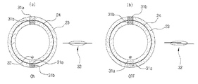
図5は図1において安全手段のオンオフ作動状態を説明するためのA−A断面図であり、図6は図1において電源供給部26の電流フロー図を説明するための図面である。
5 is a cross-sectional view taken along line AA for explaining the on / off operation state of the safety means in FIG. 1, and FIG. 6 is a diagram for explaining a current flow diagram of the
本発明の一実施例は、本体10の下端に具備された安全手段を提供して電源供給部26でケーブル25に電流が流れないように遮断することで、モータ11の過負荷による部品損傷、本体10内部とケーブル25が通電することによる不必要な電気エネルギーの消耗及び安全事故を未然に防止することができる。
In one embodiment of the present invention, the safety means provided at the lower end of the
このために、前記安全手段は、本体10の下端に設置された固定チューブ24と、固定チューブ24の外側に回転可能となるように支持される回転リング23とで固定され、前記固定チューブ24にはガイド溝が円周方向に形成されて、回転リング23がガイド溝に沿って回転することができる。
For this purpose, the safety means is fixed by a fixed
前記固定チューブ24と回転リング23には、各々鉄部31aと磁石部31bとが一定間隔、例えば、180°の間隔を置き、円周上に設置される。また、前記固定チューブ24の鉄部31aと隣接するように伝導性材質のリードスイッチ32が内側(半径方向基準)に設置され、リードスイッチ32は電源供給部26のリレー29と連結される。
In the fixed
このとき、前記電源供給部26でバッテリー27の陰極は、基板28、リレー29及び連結ジャック30に第1電線により連結され、バッテリー27の陽極は、基板28及び連結ジャック30に第2電線により連結される。
At this time, in the
このような構成による安全手段の作動状態を説明すると次の通りである。 The operating state of the safety means having such a configuration will be described as follows.
前記回転リング23は作業者が必要に応じて左右に回転させることができ、例えば、回転リング23を片側に180°回転させると、回転リング23の磁石部31bが固定チューブ24の鉄部31aに、そして回転リング23の鉄部31aが固定チューブ24の磁石部31bに引っ付くことによって、回転リング23の磁石部31bが、固定チューブ24の鉄部31aに隣接するように設置されたリードスイッチ32の接点を磁気力により互いに連結させて、リードスイッチ32がオンとなる。
The rotating
従って、前記リードスイッチ32のオン信号によりリレー29がオンとなりバッテリー27の電源がケーブル25を通して本体10のモータ11に供給され、モータ11で発生された回転力をギア装置を通して稼動刃14に伝達することで、自動で稼動刃14を動かして剪定作業を実施する。
Accordingly, the relay 29 is turned on by the ON signal of the
反面、回転リング23を反対方向または同一方向に180°回転させると、回転リング23の磁石部31bが固定チューブ24の磁石部31bに、そして回転リング23の鉄部31aが固定チューブ24の鉄部31aに引っ付くことによって、回転リング23の磁石部31bが、固定チューブ24の鉄部31aに隣接するように設置されたリードスイッチ32から遠くなり磁気力が作用しないため、リードスイッチ32がオフとなる。
On the other hand, when the
従って、前記リードスイッチ32のオフ信号によりリレー29がオフとなり、バッテリー27の電源がケーブル25を通電されないことで、電動式剪定作業をしない場合にも、電流がケーブル25を通して本体10に通電されることによる不必要な電力消耗及び安全事故を未然に防止することができる。
Accordingly, the relay 29 is turned off by the off signal of the
このように構成された電動式剪定バサミの使用状態を見てみると次の通りである。 The usage state of the electric pruning shears thus configured is as follows.
図1及び図2に図示するように、梨の木、リンゴの木、柿の木、ブドウの木、または木質が固いミカンの木、オレンジの木、柚子の木など果樹木の剪定作業をする場合、まず作業者は輪形態の携帯用作動スイッチ20を指に挟んだ状態で本体10にある接点スイッチ33側に当てると、このときの磁力により接点スイッチ33の稼動接点33aが固定接点33b側にくっつき、これと同時に、モータ11に電源が供給されてモータ11が作動する。
即ち、モータ11が正方向に回転する。
As shown in FIGS. 1 and 2, when pruning a pear tree, an apple tree, an oak tree, a vine, or a fruit tree such as a hard citrus tree, an orange tree, or a palm tree, When a person touches the
That is, the
このようなモータ11の作動は、減速器12の作動、駆動ギア15と稼動刃14のギア部16間の歯合電動からなり、稼動刃14はヒンジピン38を中心軸として回転し、結局固定刃13と共に果樹木を切断することができるようになる。
Such an operation of the
このとき、モータ11の作動は正方向及び逆方向回転を反復する作動状態を示し、これによって稼動刃14もまた正方向回転または逆方向回転を反復しながら、固定刃13と対を成して剪定作業を行う。
At this time, the operation of the
もちろん、指に挟んだ携帯用作動スイッチ20を接点スイッチに接触している間は、モータ11の正/逆方向の反復的な作動が1回行われることを基本システムとする。
Of course, the basic system is that the
ここで、本発明の一実施例によって携帯用作動スイッチ20を本体10に内装された接点スイッチ33に継続的に当てている間は、モータ11の正/逆方向の反復的な作動が数回行われ、携帯用作動スイッチ20を離す瞬間、モータ11の作動が中断されつつ、稼動刃14の作動もまた止まる。
Here, while the
図7及び図8は図1において第1ホールセンサ17及び第2ホールセンサ18を利用した稼動刃14の1回往復回転を説明するための説明図である。
7 and 8 are explanatory views for explaining one reciprocal rotation of the working
更に、本発明の別の実施例は、稼動刃14のギア部16に回転磁石34を埋め込んで設置し、固定刃13に前記回転磁石34の位置を感知する第1及び第2ホールセンサ17,18を設置することで、携帯用作動スイッチ20を接点スイッチ33に当てるとき、稼動刃14が1回だけ往復回転するようにすることができる。
Furthermore, in another embodiment of the present invention, the first and
このとき、第1及び第2ホールセンサ17,18は、稼動刃14のギア部16に設置された回転磁石34の回転半径両端に対応するように固定刃13の脚部側上端に設置される。
At this time, the first and
例えば、前記回転磁石34が第1ホールセンサ17に移動して第1ホールセンサ17により感知されると、制御部19及び電源供給部26は第1ホールセンサ17から感知信号の入力を受けてモータ11に回転制御信号を送り、モータ11が逆方向に回転することによって稼動刃14が開く。
For example, when the rotating
反面、前記回転磁石34が第2ホールセンサ18に移動して第2ホールセンサ18により感知されると、制御部19及び電源供給部26は第2ホールセンサ18から感知信号の入力を受けてモータ11に停止制御信号を送って稼動刃14が開状態で停止される。
On the other hand, when the rotating
前記した実施例のように基板の回路変更によって接点スイッチ33に携帯用作動スイッチ20を接触し続けている間、継続的にモータ11が数回反復作動され得る構造に作ることもでき、前記ホールセンサを利用して携帯用作動スイッチ20を本体10にくっ付けてはなすごとに1回だけ往復作動され得る構造に作ることもできる。
While the
また別の実施例によって基板の回路を変更して、接点スイッチ33に携帯用作動スイッチ20を一定時間、例えば、3〜4秒間持続的に接触させる場合、稼動刃14が閉状態となるようにすることができる。この場合、前記ホールセンサを利用して稼動刃14の位置を検出してモータ11を制御することで、稼動刃14の作動が可能となる。
Further, when the circuit of the substrate is changed according to another embodiment, and the
ここで、モータ11の正方向及び逆方向回転を電気的に制御する方法などは、通常の電動式剪定バサミで採用している電気的制御方法と同様に、当技術分野で通常的に知られている方法ならば、特別に制限せず採択することができる。
Here, the method of electrically controlling the forward and reverse rotations of the
このように、電動式剪定バサミの作動のためのスイッチ手段を剪定バサミ本体10側に具備せず、別途に具備して別に保管することができるため、子供や未熟練者の不注意などによる剪定バサミの誤作動を源泉的に防ぐことができ、安全事故予防にも大きな効果が見られる。何よりも作動スイッチなどのような追加的な部品を本体10から削除することができるため、剪定バサミのサイズを小型化及び軽量化することができるなど、剪定バサミを使用する時、作業の便利性を図ることができる。
Thus, the switch means for operating the electric pruning shears is not provided on the pruning shears
10 本体
11 モータ
12 減速器
13 固定刃
14 稼動刃
15 駆動ギア
16 ギア部
17 第1ホールセンサ
18 第2ホールセンサ
19 制御部
20 携帯用作動スイッチ
21 磁石
22 支持ブロック
23 回転リング
24 固定チューブ
25 ケーブル
26 電源供給部
27 バッテリー
28 基板
29 リレー
30 連結ジャック
31a 鉄部
31b 磁石部
32 リードスイッチ
33 接点スイッチ
33a 稼動接点
33b 固定接点
34 回転磁石
35 板膜
36 ホールセンサタイプのスイッチ
36a、36b 板
37 ロードセル
38 ヒンジピン
DESCRIPTION OF
Claims (12)
前記モータの作動のために本体の片側に設置され、稼動接点及び固定接点とで構成される接点スイッチと、
指に挟むことができる別途の輪形態からなり、磁石を内装して磁力で接点スイッチの稼動接点と固定接点をくっ付けることで、モータを作動させることができる携帯用作動スイッチと、
を更に含むことを特徴とする電動式剪定バサミ。 In the electric pruning shears that comprise a fixed blade and an operating blade and perform the pruning work by operating the operating blade with the driving force of the motor,
A contact switch that is installed on one side of the main body for the operation of the motor and is composed of an operating contact and a fixed contact;
A portable operation switch that can be operated by a motor with a separate ring form that can be sandwiched between fingers, and that has an internal magnet and attaches the operating contact and fixed contact of the contact switch magnetically.
An electric pruning shears further comprising:
前記固定チューブの外表面に同心円状に回転が可能となるように支持される回転リングと、
前記回転リングを操作して磁気力によりオンまたはオフとなるリードスイッチと、
を更に含むことを特徴とする、請求項1記載の電動式剪定バサミ。 A fixed tube installed at the lower end of the main body;
A rotating ring supported so as to be concentrically rotatable on the outer surface of the fixed tube;
A reed switch that is turned on or off by a magnetic force by operating the rotating ring;
The electric pruning shears according to claim 1, further comprising:
前記モータの作動のために本体の片側に設置されたホールセンサタイプのスイッチと、
磁石を内装してホールセンサタイプのスイッチに接触することで、磁石にてスイッチをオンにしてモータを作動させる携帯用作動スイッチと、
を含む電動式剪定バサミ。 In the electric pruning shears that have a fixed blade and an operating blade and perform the pruning work by operating the operating blade with the driving force of the motor,
Hall sensor type switch installed on one side of the main body for the operation of the motor,
A portable operation switch that operates the motor by turning on the switch with a magnet by touching the hall sensor type switch with a magnet built in,
Electric pruning shears including
Applications Claiming Priority (4)
| Application Number | Priority Date | Filing Date | Title |
|---|---|---|---|
| KR20080090800 | 2008-09-16 | ||
| KR10-2008-0090800 | 2008-09-16 | ||
| KR10-2009-0052220 | 2009-06-12 | ||
| KR1020090052220A KR101166700B1 (en) | 2008-09-16 | 2009-06-12 | Electromotion trim scissors |
Publications (2)
| Publication Number | Publication Date |
|---|---|
| JP2010068802A true JP2010068802A (en) | 2010-04-02 |
| JP5088512B2 JP5088512B2 (en) | 2012-12-05 |
Family
ID=42181606
Family Applications (1)
| Application Number | Title | Priority Date | Filing Date |
|---|---|---|---|
| JP2009201322A Active JP5088512B2 (en) | 2008-09-16 | 2009-09-01 | Electric pruning shears |
Country Status (2)
| Country | Link |
|---|---|
| JP (1) | JP5088512B2 (en) |
| KR (1) | KR101166700B1 (en) |
Cited By (4)
| Publication number | Priority date | Publication date | Assignee | Title |
|---|---|---|---|---|
| JP2017056196A (en) * | 2015-09-14 | 2017-03-23 | マックス株式会社 | Foreign matter detection mechanism for electric scissors |
| JP2021170956A (en) * | 2020-04-21 | 2021-11-01 | アルスコーポレーション株式会社 | Electric pruning shears |
| CN114473026A (en) * | 2020-10-26 | 2022-05-13 | 施耐宝公司 | Portable electric rescue tool |
| WO2022244371A1 (en) * | 2021-05-17 | 2022-11-24 | 株式会社フジクラ | Method and system for manufacturing optical fiber tape |
Families Citing this family (7)
| Publication number | Priority date | Publication date | Assignee | Title |
|---|---|---|---|---|
| CN104985092B (en) * | 2015-07-26 | 2017-02-01 | 江苏新技机械有限公司 | Wire cutting device of wire coiling machine |
| EP3430885B1 (en) * | 2015-09-14 | 2019-12-04 | Max Co., Ltd. | Foreign matter detecting mechanism of electric scissors |
| WO2018205126A1 (en) * | 2017-05-09 | 2018-11-15 | Tti (Macao Commercial Offshore) Limited | A power tool and a driving mechanism for use in a power tool |
| KR102620741B1 (en) | 2021-04-19 | 2024-01-15 | 주식회사 아임삭 | Pruning Shears with Branched Fixation and Electromotion Pruning Shears having the Same |
| KR20230068191A (en) | 2021-11-10 | 2023-05-17 | 주식회사 에스엠유니트 | Electric scissors |
| KR20230075933A (en) | 2021-11-23 | 2023-05-31 | 주식회사 에스엠유니트 | Safety electric scissors |
| KR20230086969A (en) | 2021-12-09 | 2023-06-16 | 주식회사 에스엠유니트 | Electric trim scissors |
Citations (5)
| Publication number | Priority date | Publication date | Assignee | Title |
|---|---|---|---|---|
| JPS4927087Y1 (en) * | 1970-11-02 | 1974-07-23 | ||
| JPS5612954U (en) * | 1979-07-11 | 1981-02-03 | ||
| JPH08200942A (en) * | 1994-08-27 | 1996-08-09 | Lg Electronics Inc | Opening-closing sensing circuit for refrigerator door utilizing hole sensor |
| JPH0970220A (en) * | 1995-09-06 | 1997-03-18 | Iseki & Co Ltd | Threshing and nipping-transfer controller in combine |
| JP2005224122A (en) * | 2004-02-10 | 2005-08-25 | Vessel Fukuchiyama:Kk | Electric shears |
Family Cites Families (1)
| Publication number | Priority date | Publication date | Assignee | Title |
|---|---|---|---|---|
| KR100699197B1 (en) * | 2007-01-22 | 2007-03-28 | (주)금오전자 | Electromotion Trim Scissors |
-
2009
- 2009-06-12 KR KR1020090052220A patent/KR101166700B1/en active IP Right Grant
- 2009-09-01 JP JP2009201322A patent/JP5088512B2/en active Active
Patent Citations (5)
| Publication number | Priority date | Publication date | Assignee | Title |
|---|---|---|---|---|
| JPS4927087Y1 (en) * | 1970-11-02 | 1974-07-23 | ||
| JPS5612954U (en) * | 1979-07-11 | 1981-02-03 | ||
| JPH08200942A (en) * | 1994-08-27 | 1996-08-09 | Lg Electronics Inc | Opening-closing sensing circuit for refrigerator door utilizing hole sensor |
| JPH0970220A (en) * | 1995-09-06 | 1997-03-18 | Iseki & Co Ltd | Threshing and nipping-transfer controller in combine |
| JP2005224122A (en) * | 2004-02-10 | 2005-08-25 | Vessel Fukuchiyama:Kk | Electric shears |
Cited By (4)
| Publication number | Priority date | Publication date | Assignee | Title |
|---|---|---|---|---|
| JP2017056196A (en) * | 2015-09-14 | 2017-03-23 | マックス株式会社 | Foreign matter detection mechanism for electric scissors |
| JP2021170956A (en) * | 2020-04-21 | 2021-11-01 | アルスコーポレーション株式会社 | Electric pruning shears |
| CN114473026A (en) * | 2020-10-26 | 2022-05-13 | 施耐宝公司 | Portable electric rescue tool |
| WO2022244371A1 (en) * | 2021-05-17 | 2022-11-24 | 株式会社フジクラ | Method and system for manufacturing optical fiber tape |
Also Published As
| Publication number | Publication date |
|---|---|
| JP5088512B2 (en) | 2012-12-05 |
| KR101166700B1 (en) | 2012-07-27 |
| KR20100032290A (en) | 2010-03-25 |
Similar Documents
| Publication | Publication Date | Title |
|---|---|---|
| JP5088512B2 (en) | Electric pruning shears | |
| US8276280B2 (en) | Electromotion trim scissors | |
| KR101132328B1 (en) | electric-pruning shears with trigger. | |
| US7676879B1 (en) | Battery-powered sewer and drain cleaner | |
| US20100313430A1 (en) | Method for controlling reversal of a blade of a bush cutter | |
| US20120246942A1 (en) | Power pruner | |
| KR101713622B1 (en) | pruning shears | |
| CN107614222A (en) | Chain saw | |
| JP2011067609A (en) | Human grasp assist device and method of use | |
| JP2006000109A (en) | Operation-sensing controller and walk-behind type lawn mower | |
| CN108430714B (en) | Auxiliary implement | |
| EP2327656A3 (en) | Aerial lift with safety device | |
| CN208446052U (en) | Rope type trimmer and vegetation cutter device | |
| WO2016056456A1 (en) | Electric chainsaw | |
| CN104066557A (en) | Chainsaw | |
| BR112017007570B1 (en) | PROCESS AND CONTROL DEVICE FOR EQUIPMENT WITH MOTOR AND PORTABLE POWER TOOL | |
| EP3398726A1 (en) | Trigger potentiometer | |
| KR101009378B1 (en) | Carried pruning shears | |
| JPH0736611U (en) | Electric mower | |
| JP5580795B2 (en) | Electric working machine control device and electric working machine | |
| EP3308622A1 (en) | Powered spool line winding mechanism for string trimmer | |
| JP5807652B2 (en) | Electric field cultivator | |
| JP2011147375A (en) | Implement and method for controlling implement | |
| JP5761276B2 (en) | Walk-type field cultivator | |
| JP6060043B2 (en) | Mower |
Legal Events
| Date | Code | Title | Description |
|---|---|---|---|
| A977 | Report on retrieval |
Free format text: JAPANESE INTERMEDIATE CODE: A971007 Effective date: 20110620 |
|
| A131 | Notification of reasons for refusal |
Free format text: JAPANESE INTERMEDIATE CODE: A131 Effective date: 20120213 |
|
| A521 | Request for written amendment filed |
Free format text: JAPANESE INTERMEDIATE CODE: A523 Effective date: 20120508 |
|
| TRDD | Decision of grant or rejection written | ||
| A01 | Written decision to grant a patent or to grant a registration (utility model) |
Free format text: JAPANESE INTERMEDIATE CODE: A01 Effective date: 20120820 |
|
| A01 | Written decision to grant a patent or to grant a registration (utility model) |
Free format text: JAPANESE INTERMEDIATE CODE: A01 |
|
| A61 | First payment of annual fees (during grant procedure) |
Free format text: JAPANESE INTERMEDIATE CODE: A61 Effective date: 20120828 |
|
| FPAY | Renewal fee payment (event date is renewal date of database) |
Free format text: PAYMENT UNTIL: 20150921 Year of fee payment: 3 |
|
| R150 | Certificate of patent or registration of utility model |
Ref document number: 5088512 Country of ref document: JP Free format text: JAPANESE INTERMEDIATE CODE: R150 Free format text: JAPANESE INTERMEDIATE CODE: R150 |
|
| R250 | Receipt of annual fees |
Free format text: JAPANESE INTERMEDIATE CODE: R250 |
|
| R250 | Receipt of annual fees |
Free format text: JAPANESE INTERMEDIATE CODE: R250 |
|
| R250 | Receipt of annual fees |
Free format text: JAPANESE INTERMEDIATE CODE: R250 |
|
| R250 | Receipt of annual fees |
Free format text: JAPANESE INTERMEDIATE CODE: R250 |
|
| R250 | Receipt of annual fees |
Free format text: JAPANESE INTERMEDIATE CODE: R250 |
|
| R250 | Receipt of annual fees |
Free format text: JAPANESE INTERMEDIATE CODE: R250 |
|
| R250 | Receipt of annual fees |
Free format text: JAPANESE INTERMEDIATE CODE: R250 |
|
| R250 | Receipt of annual fees |
Free format text: JAPANESE INTERMEDIATE CODE: R250 |
|
| R250 | Receipt of annual fees |
Free format text: JAPANESE INTERMEDIATE CODE: R250 |