JP2010068051A - Relay server and relay communication system - Google Patents
Relay server and relay communication system Download PDFInfo
- Publication number
- JP2010068051A JP2010068051A JP2008230229A JP2008230229A JP2010068051A JP 2010068051 A JP2010068051 A JP 2010068051A JP 2008230229 A JP2008230229 A JP 2008230229A JP 2008230229 A JP2008230229 A JP 2008230229A JP 2010068051 A JP2010068051 A JP 2010068051A
- Authority
- JP
- Japan
- Prior art keywords
- relay
- information
- relay server
- client terminal
- server
- Prior art date
- Legal status (The legal status is an assumption and is not a legal conclusion. Google has not performed a legal analysis and makes no representation as to the accuracy of the status listed.)
- Granted
Links
Images


Abstract
Description
本発明は、遠隔のLAN(Local Area Network)に接続されるクライアント端末が、WAN(Wide Area Network)を超えて通信することを可能にする中継サーバおよび中継通信システムに関する。 The present invention relates to a relay server and a relay communication system that enable a client terminal connected to a remote LAN (Local Area Network) to communicate over a WAN (Wide Area Network).
遠隔のLANに接続されるクライアント端末が、WANを超えて通信することがある。VPN(Virtual Private Network)は、遠隔のLANが直接に接続されているかのようなネットワークを構築できる。しかし、VPNは、拡張性および柔軟性のあるネットワークを構築することが困難である。 A client terminal connected to a remote LAN may communicate over a WAN. A VPN (Virtual Private Network) can construct a network as if a remote LAN is directly connected. However, it is difficult for VPN to build a scalable and flexible network.
特許文献1が開示する中継通信システムは、VPNと同様に、遠隔のLANが直接に接続されているかのようなネットワークを構築できる。そして、中継通信システムは、VPNと異なり、拡張性および柔軟性のあるネットワークを構築することが容易である。
The relay communication system disclosed in
中継通信システムは、WAN、複数のLANを備える。各LANは、中継サーバを備える。各中継サーバは、中継通信システムが備える中継サーバについての中継グループ情報、中継通信システムが共有するリソースについての共有リソース情報を格納する。 The relay communication system includes a WAN and a plurality of LANs. Each LAN includes a relay server. Each relay server stores relay group information about a relay server included in the relay communication system and shared resource information about a resource shared by the relay communication system.
一のLANに接続されるクライアント端末が、他のLANに接続されるクライアント端末が格納するリソースを操作するときには、これらのLANに接続される中継サーバは、中継グループ情報および共有リソース情報に基づいて、リソースの操作を中継する。 When a client terminal connected to one LAN operates a resource stored in a client terminal connected to another LAN, the relay server connected to these LANs is based on the relay group information and the shared resource information. , Relay resource operations.
中継通信システムが備えるLANが増減することがある。中継通信システムが共有するリソースが更新されることがある。しかし、中継通信システムは、これらの変化に対応して、中継グループ情報および共有リソース情報を更新できる。そして、中継通信システムは、これらの変化に対応して、拡張性および柔軟性のあるネットワークを構築できる。 The number of LANs included in the relay communication system may increase or decrease. Resources shared by the relay communication system may be updated. However, the relay communication system can update the relay group information and the shared resource information in response to these changes. And the relay communication system can construct | assemble a network with an expandability and flexibility corresponding to these changes.
特許文献1が開示する中継通信システムにおいて、LANおよびクライアント端末の増減状態および接続状態が変化することがある。しかし、クライアント端末および中継サーバが通信先を指定するにあたり、装置の増減状態および接続状態をリアルタイムに確認する具体的な手段は開示されていない。さらに、装置の増減状態および接続状態が変化するとしても、クライアント端末および中継サーバが仮想IP(Internet Protocol)アドレスを動的に割り付けられる具体的な手段は開示されていない。
In the relay communication system disclosed in
そこで、本発明は前記問題点に鑑み、遠隔のLANに接続されるクライアント端末がWANを超えて通信することを可能にする中継通信システムにおいて、クライアント端末および中継サーバが通信先を指定するにあたり、装置の増減状態および接続状態をリアルタイムに確認する具体的な手段を提供することを目的とする。さらに、装置の増減状態および接続状態が変化するとしても、クライアント端末および中継サーバが仮想IPアドレスを動的に割り付けられる具体的な手段を提供することを目的とする。 Therefore, in view of the above problems, in the relay communication system that enables a client terminal connected to a remote LAN to communicate over a WAN, the client terminal and the relay server specify a communication destination. It is an object of the present invention to provide a specific means for confirming an increase / decrease state and a connection state of devices in real time. It is another object of the present invention to provide a specific means by which a client terminal and a relay server can dynamically allocate a virtual IP address even when the increase / decrease state and connection state of devices change.
上記課題を解決するため、請求項1記載の発明は、第1ネットワークと、第2ネットワークと、前記第1ネットワークに接続される第1中継サーバと、前記第2ネットワークに接続される第2中継サーバと、を備える中継通信システムであって、前記第1中継サーバと前記第2中継サーバとは、前記第1中継サーバと前記第2中継サーバとが構成する中継グループと、前記中継グループで利用する仮想ネットワークアドレスと、を示す中継グループ情報を作成する中継グループ情報作成部、を含み、前記第1中継サーバは、前記第1中継サーバの起動状態を示す第1中継サーバ起動情報と、前記第1中継サーバと前記第1ネットワークに接続される第1クライアント端末との間の接続状態を含め前記第1中継サーバに登録されている前記第1クライアント端末に関する第1クライアント端末登録情報と、を含む第1中継サーバ情報を作成する第1中継サーバ情報作成部、を含み、前記第2中継サーバは、前記第2中継サーバの起動状態を示す第2中継サーバ起動情報と、前記第2中継サーバと前記第2ネットワークに接続される第2クライアント端末との間の接続状態を含め前記第2中継サーバに登録されている前記第2クライアント端末に関する第2クライアント端末登録情報と、を含む第2中継サーバ情報を作成する第2中継サーバ情報作成部、を含み、前記第1中継サーバと前記第2中継サーバとは、前記第1中継サーバ情報と前記第2中継サーバ情報と、を含む中継サーバ情報と、前記中継グループ情報とを、前記第1中継サーバと前記第2中継サーバとの間で共有する中継サーバ間共有部と、所定のタイミングで前記第1クライアント端末および前記第2クライアント端末に前記中継グループ内でユニークとなるよう管理された仮想ネットワークアドレスを動的に付与するとともに、付与した仮想ネットワークアドレスの情報を前記中継サーバ情報に登録する仮想アドレス管理部と、を含み、前記第1中継サーバは、前記中継グループ情報と前記中継サーバ情報とを前記第1中継サーバと前記第1クライアント端末との間で共有する第1クライアント端末間共有部、を含み、前記第2中継サーバは、前記中継グループ情報と前記中継サーバ情報とを前記第2中継サーバと前記第2クライアント端末との間で共有する第2クライアント端末間共有部、を含むことを特徴とする。
In order to solve the above problem, the invention described in
請求項2記載の発明は、請求項1に記載の中継通信システムにおいて、前記中継グループ情報は、前記第1中継サーバと前記第2中継サーバがコネクションを確立しているかどうかについての中継サーバコネクション確立情報、を含み、前記第1中継サーバ情報は、前記第1クライアント端末が前記第1中継サーバとコネクションを確立しているかどうかについての第1クライアント端末コネクション確立情報、を含み、前記第2中継サーバ情報は、前記第2クライアント端末が前記第2中継サーバとコネクションを確立しているかどうかについての第2クライアント端末コネクション確立情報、を含むことを特徴とする。 According to a second aspect of the present invention, in the relay communication system according to the first aspect, the relay group information includes a relay server connection establishment as to whether the first relay server and the second relay server have established a connection. The first relay server information includes first client terminal connection establishment information as to whether or not the first client terminal has established a connection with the first relay server, and the second relay server The information includes second client terminal connection establishment information as to whether or not the second client terminal has established a connection with the second relay server.
請求項3記載の発明は、請求項1または請求項2に記載の中継通信システムにおいて、前記第1中継サーバは、前記中継グループ情報と前記中継サーバ情報とに基づいて選択された前記第2ネットワークの仮想ネットワークアドレスが通信先として指定された、前記第1中継サーバが中継する通信を、前記中継グループ情報と前記中継サーバ情報とに基づいて実行する通信実行部、を含むことを特徴とする。 A third aspect of the present invention is the relay communication system according to the first or second aspect, wherein the first relay server is selected based on the relay group information and the relay server information. A communication execution unit that executes communication relayed by the first relay server, with the virtual network address specified as a communication destination, based on the relay group information and the relay server information.
請求項4記載の発明は、請求項1ないし請求項3のいずれかに記載の中継通信システムにおいて、前記第1中継サーバと前記第1クライアント端末とは、前記中継グループ情報と前記中継サーバ情報とに基づいて、現在の前記中継グループ内のコネクションの確立状況と仮想アドレスとを視覚的に表すマップを表示するマップ表示部、を含むことを特徴とする。 According to a fourth aspect of the present invention, in the relay communication system according to any one of the first to third aspects, the first relay server and the first client terminal include the relay group information, the relay server information, And a map display unit for displaying a map visually representing a connection establishment status and a virtual address in the current relay group.
中継通信システムは、第1ネットワークおよび第2ネットワークを備える。第1ネットワークは、第1中継サーバおよび第1クライアント端末を備える。第2ネットワークは、第2中継サーバおよび第2クライアント端末を備える。第1中継サーバおよび第2中継サーバは、第1クライアント端末および第2クライアント端末の相互間の通信を中継する。 The relay communication system includes a first network and a second network. The first network includes a first relay server and a first client terminal. The second network includes a second relay server and a second client terminal. The first relay server and the second relay server relay communication between the first client terminal and the second client terminal.
第1(第2)中継サーバは、中継グループ情報、第1(第2)中継サーバ情報、クライアント端末情報を作成する。中継グループ情報は、第1中継サーバおよび第2中継サーバが構成する中継グループと、第1中継サーバと第2中継サーバに割り付けられる仮想ネットワークアドレスと、第1中継サーバと第2中継サーバがコネクションを確立しているかと、を示す情報である。第1(第2)中継サーバ情報は、第1(第2)中継サーバと通信可能である第1(第2)クライアント端末と、第1(第2)クライアント端末に割り付けられる仮想ネットワークアドレスと、第1(第2)クライアント端末がコネクションを確立しているかと、を示す情報である。クライアント端末情報は、第1(第2)クライアント端末の第1(第2)ネットワークにおける接続環境を示す情報である。 The first (second) relay server creates relay group information, first (second) relay server information, and client terminal information. The relay group information includes a relay group formed by the first relay server and the second relay server, a virtual network address assigned to the first relay server and the second relay server, and a connection between the first relay server and the second relay server. It is information indicating whether it is established. The first (second) relay server information includes a first (second) client terminal capable of communicating with the first (second) relay server, a virtual network address assigned to the first (second) client terminal, This is information indicating whether the first (second) client terminal has established a connection. The client terminal information is information indicating a connection environment of the first (second) client terminal in the first (second) network.
第1(第2)中継サーバは、中継グループ情報を参照することにより、第1中継サーバ情報および第2中継サーバ情報を、第1中継サーバおよび第2中継サーバの相互間において共有できる。第1(第2)中継サーバは、第1中継サーバ情報および第2中継サーバ情報を合成して、中継サーバ情報を作成できる。第1(第2)中継サーバは、各々のクライアント端末情報を参照することにより、中継グループ情報および中継サーバ情報を、第1(第2)中継サーバおよび第1(第2)クライアント端末の相互間において共有できる。 The first (second) relay server can share the first relay server information and the second relay server information between the first relay server and the second relay server by referring to the relay group information. The first (second) relay server can create the relay server information by combining the first relay server information and the second relay server information. The first (second) relay server refers to each client terminal information so that the relay group information and the relay server information can be obtained between the first (second) relay server and the first (second) client terminal. Can share.
中継通信システム内の各装置は、装置の増減状態および接続状態についての情報を、リアルタイムに共有できる。中継通信システム内の各装置は、装置の仮想ネットワークアドレスおよびコネクション確立についての情報を、リアルタイムに共有できる。中継通信システム内の各装置は、中継通信システムの状態変化に対応して、仮想ネットワークアドレスが通信先として指定された通信を柔軟に実行できる。 Each device in the relay communication system can share information on the increase / decrease state and connection state of the device in real time. Each device in the relay communication system can share information on the virtual network address of the device and connection establishment in real time. Each device in the relay communication system can flexibly execute communication in which a virtual network address is designated as a communication destination in response to a change in the state of the relay communication system.
{中継通信システムの全体構成}
以下、図面を参照しつつ、本発明の実施の形態について説明する。図1は、中継通信システムの全体構成を示す図である。中継通信システムは、LAN1、2、WAN3から構成される。LAN1、2は、遠隔に構築される小規模なネットワークである。WAN3は、インターネットなどの大規模なネットワークである。
{Overall configuration of relay communication system}
Hereinafter, embodiments of the present invention will be described with reference to the drawings. FIG. 1 is a diagram illustrating an overall configuration of a relay communication system. The relay communication system includes
LAN1は、クライアント端末11、中継サーバ12から構成される。LAN2は、クライアント端末21、中継サーバ22から構成される。WAN3は、SIP(Session Initiation Protocol)サーバ31から構成される。
The
クライアント端末11、21は、パーソナルコンピュータなどである。中継サーバ12、22は、クライアント端末11、21の相互間の通信を中継する。SIPサーバ31は、中継サーバ12、22の相互間の通信を中継する。
The
本実施の形態においては、中継サーバ12、22の相互間の通信プロトコルとして、SIPを利用するが、SIP以外のプロトコルを利用してもよい。SIP以外のプロトコルを利用するときには、中継サーバ12、22の相互間の通信が直接に実行されればよい。
In the present embodiment, SIP is used as a communication protocol between the
{中継サーバの構成要素}
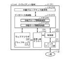
図2は、中継サーバ12(22)の構成要素を示す図である。中継サーバ12(22)は、インターフェース部121(221)、制御部122(222)、データベース格納部123(223)、中継グループマップ表示部127(227)、仮想LANドライバ128(228)から構成される。括弧が付されていない符号は、中継サーバ12における符号を示す。括弧が付されている符号は、中継サーバ22における符号を示す。
{Components of relay server}
FIG. 2 is a diagram showing components of the relay server 12 (22). The relay server 12 (22) includes an interface unit 121 (221), a control unit 122 (222), a database storage unit 123 (223), a relay group map display unit 127 (227), and a virtual LAN driver 128 (228). The A code without parentheses indicates a code in the
インターフェース部121(221)は、プライベートIPアドレスを利用して、LAN1(2)に接続されるクライアント端末11(21)に対して通信を実行する。インターフェース部121(221)は、グローバルIPアドレスを利用して、WAN3に接続されるSIPサーバ31に対して通信を実行する。
The interface unit 121 (221) performs communication with the client terminal 11 (21) connected to the LAN 1 (2) using the private IP address. The interface unit 121 (221) performs communication with the
制御部122(222)は、クライアント端末11、21の相互間の通信を中継するための制御を行なう。制御部122(222)は、データベース格納部123(223)に格納される以下の情報を作成または更新する。
The control unit 122 (222) performs control for relaying communication between the
データベース格納部123(223)は、中継グループ情報格納部124(224)、中継サーバ情報格納部125(225)、クライアント端末情報格納部126(226)から構成される。中継グループマップ表示部127(227)は、中継グループ情報および中継サーバ情報を参照することにより、中継グループマップを中継サーバ12(22)において表示する。仮想LANドライバ128(228)は、中継通信システムにおいて仮想的に割り付けられた、中継サーバ12(22)の仮想プライベートIPアドレスを登録する。中継通信システムにおいて、各中継サーバに対して、仮想プライベートIPアドレスが割り付けられる方法については後述する。また、以上の情報および中継グループマップの具体例についても後述する。 The database storage unit 123 (223) includes a relay group information storage unit 124 (224), a relay server information storage unit 125 (225), and a client terminal information storage unit 126 (226). The relay group map display unit 127 (227) displays the relay group map on the relay server 12 (22) by referring to the relay group information and the relay server information. The virtual LAN driver 128 (228) registers the virtual private IP address of the relay server 12 (22) virtually allocated in the relay communication system. A method for assigning a virtual private IP address to each relay server in the relay communication system will be described later. Also, specific examples of the above information and relay group map will be described later.
{クライアント端末の構成要素}
図3は、クライアント端末11(21)の構成要素を示す図である。クライアント端末11(21)は、インターフェース部111(211)、制御部112(212)、ウェブブラウザ113(ウェブサーバ213)、仮想LANドライバ114(214)、データベース格納部115(215)、中継グループマップ表示部118(218)から構成される。括弧が付されていない符号は、クライアント端末11における符号を示す。括弧が付されている符号は、クライアント端末21における符号を示す。
{Components of client terminal}
FIG. 3 shows the components of the client terminal 11 (21). The client terminal 11 (21) includes an interface unit 111 (211), a control unit 112 (212), a web browser 113 (web server 213), a virtual LAN driver 114 (214), a database storage unit 115 (215), a relay group map. It is comprised from the display part 118 (218). Reference numerals without parentheses indicate reference numerals in the
インターフェース部111(211)は、プライベートIPアドレスを利用して、LAN1(2)に接続される中継サーバ12(22)に対して通信を実行する。 The interface unit 111 (211) performs communication with the relay server 12 (22) connected to the LAN 1 (2) using the private IP address.
制御部112(212)は、クライアント端末11(21)および中継サーバ12(22)の相互間の通信を実行するための制御を行なう。 The control unit 112 (212) performs control for executing communication between the client terminal 11 (21) and the relay server 12 (22).
制御部112(212)は、ウェブブラウザ113(ウェブサーバ213)に処理される情報を入力または出力する。ウェブブラウザ113は、ウェブサーバ213に対して、WAN3を介して、コンテンツを要求する。ウェブサーバ213は、ウェブブラウザ113に対して、WAN3を介して、コンテンツを提供する。
The control unit 112 (212) inputs or outputs information to be processed by the web browser 113 (web server 213). The
仮想LANドライバ114(214)は、中継通信システムにおいて仮想的に割り付けられた、クライアント端末11(21)の仮想プライベートIPアドレスを登録する。中継通信システムにおいて、各クライアント端末に対して、仮想プライベートIPアドレスが割り付けられる方法については後述する。 The virtual LAN driver 114 (214) registers the virtual private IP address of the client terminal 11 (21) virtually allocated in the relay communication system. A method of assigning a virtual private IP address to each client terminal in the relay communication system will be described later.
制御部112(212)は、データベース格納部115(215)に格納される以下の情報を作成または更新する。データベース格納部115(215)は、中継グループ情報格納部116(216)、中継サーバ情報格納部117(217)から構成される。中継グループマップ表示部118(218)は、中継グループ情報および中継サーバ情報を参照することにより、中継グループマップをクライアント端末11(21)において表示する。以上の情報および中継グループマップの具体例について後述する。 The control unit 112 (212) creates or updates the following information stored in the database storage unit 115 (215). The database storage unit 115 (215) includes a relay group information storage unit 116 (216) and a relay server information storage unit 117 (217). The relay group map display unit 118 (218) displays the relay group map on the client terminal 11 (21) by referring to the relay group information and the relay server information. Specific examples of the above information and relay group map will be described later.
{中継グループ情報の具体例}
図4は、中継グループ情報の具体例として、中継グループ情報40を示す図である。中継グループ情報は、中継通信システムを構成する中継サーバの概要を示す情報である。
{Specific example of relay group information}
FIG. 4 is a diagram illustrating the relay group information 40 as a specific example of the relay group information. The relay group information is information indicating an outline of the relay server that constitutes the relay communication system.
中継グループ情報40は、上位情報401、下位情報402から構成される。上位情報401は、中継グループ仮想アドレス情報403を含む。下位情報402は、中継サーバ仮想アドレス情報404、コネクション確立情報405を含む。
The relay group information 40 includes
上位情報401は、上位にある中継グループについての情報である。「id」は、中継グループの識別情報を示す。「lastmod」は、中継グループ情報の最新更新時刻を示す。「name」は、中継グループの名称を示す。中継グループ仮想アドレス情報403は、中継通信システムにおいて仮想的に割り付けられた、中継グループの仮想プライベートIPアドレス(ネットワークアドレス)を示す。中継通信システムにおいて、サブネットマスクは「255.255.255.0」に設定されて、「*」は各装置に一意に設定される。
The
下位情報402は、下位にある中継サーバについての情報である。「id」は、中継サーバの識別情報を示す。中継サーバ仮想アドレス情報404は、中継通信システムにおいて仮想的に割り付けられた、中継サーバの仮想プライベートIPアドレスを示す。コネクション確立情報405は、WAN3を介する各中継サーバの相互間において、コネクションが確立されているかどうかについての情報である。
The
中継グループ情報40は、中継グループ情報格納部124、224、116、216において格納される。すなわち、中継グループ情報40は、中継サーバ12、22およびクライアント端末11、21により共有される。
The relay group information 40 is stored in the relay group
WAN3を介する各中継サーバの相互間において、仮想アドレスを利用したIP通信用のコネクションが確立されているときには、コネクション確立情報405が記載されている。WAN3を介する各中継サーバの相互間において、仮想アドレスを利用したIP通信用のコネクションが確立されていないときには、コネクション確立情報405が記載されていない。これにより、WAN3を介する各中継サーバの相互間において、仮想アドレスを利用したIP通信用のコネクションが確立されているかどうかについての情報が、中継通信システム全体として共有される。さらに、中継サーバの仮想プライベートIPアドレスについての情報が、中継通信システム全体として共有される。
When a connection for IP communication using a virtual address is established between the relay servers via the
{中継サーバ情報の具体例}
図5は、中継サーバ情報の具体例として、中継サーバ情報50を示す図である。中継サーバ情報は、中継通信システムを構成する中継サーバの詳細を示す情報であり、中継通信システムを構成するクライアント端末の概要を示す情報である。
{Specific example of relay server information}
FIG. 5 is a diagram showing relay server information 50 as a specific example of the relay server information. The relay server information is information that indicates details of the relay server that constitutes the relay communication system, and is an information that indicates an outline of the client terminal that constitutes the relay communication system.
中継サーバ情報50は、上位情報501−1、501−2、下位情報502−1、502−2から構成される。上位情報501−1、501−2は、各々、中継サーバ起動情報503−1、503−2を含む。下位情報502−1、502−2は、各々、クライアント端末仮想アドレス情報504−1、504−2、コネクション確立情報505−1、505−2、クライアント端末が中継サーバにログインしているかどうかを示すクライアント端末サイト情報506−1、506−2を含む。 The relay server information 50 includes upper information 501-1 and 501-2 and lower information 502-1 and 502-2. The upper information 501-1 and 501-2 include relay server activation information 503-1 and 503-2, respectively. The lower information 502-1 and 502-2 indicate client terminal virtual address information 504-1 and 504-2, connection establishment information 505-1 and 505-2, and whether the client terminal is logged in to the relay server, respectively. Client terminal site information 506-1 and 506-2 are included.
上位情報501−1、501−2は、上位にある中継サーバについての情報である。「id」は、中継サーバの識別情報を示す。「name」は、中継サーバの名称を示す。中継サーバ起動情報503−1、503−2は、中継サーバが起動しているかどうかについての情報である。 The upper information 501-1 and 501-2 are information on the relay server at the upper level. “Id” indicates identification information of the relay server. “Name” indicates the name of the relay server. The relay server activation information 503-1 and 503-2 are information about whether the relay server is activated.
下位情報502−1、502−2は、下位にあるクライアント端末についての情報である。「div」は、クライアント端末の部署名を示す。「group」は、クライアント端末が所属する中継グループの識別情報を示す。「id」は、クライアント端末の識別情報を示す。「name」は、クライアント端末の名称を示す。 The lower information 502-1 and 502-2 are information about the lower client terminals. “Div” indicates a department name of the client terminal. “Group” indicates identification information of the relay group to which the client terminal belongs. “Id” indicates identification information of the client terminal. “Name” indicates the name of the client terminal.
クライアント端末仮想アドレス情報504−1、504−2は、中継通信システムにおいて仮想的に割り付けられた、クライアント端末の仮想プライベートIPアドレスを示す。コネクション確立情報505−1、505−2は、同一のLANにおけるクライアント端末および中継サーバの相互間において、仮想アドレスを利用したIP通信用のコネクションが確立されているかどうかについての情報である。クライアント端末サイト情報506−1、506−2は、クライアント端末がログオンしている中継サーバの識別情報を示す。 The client terminal virtual address information 504-1 and 504-2 indicate virtual private IP addresses of client terminals virtually allocated in the relay communication system. The connection establishment information 505-1 and 505-2 are information about whether or not a connection for IP communication using a virtual address is established between a client terminal and a relay server in the same LAN. Client terminal site information 506-1 and 506-2 indicate identification information of the relay server to which the client terminal is logged on.
中継サーバ情報50は、中継サーバ情報格納部125、225、117、217において格納される。すなわち、中継サーバ情報50は、中継サーバ12、22およびクライアント端末11、21により共有される。
The relay server information 50 is stored in the relay server
中継サーバが起動しているときには、中継サーバ起動情報503−1、503−2が「active」になっている。中継サーバが起動していないときには、中継サーバ起動情報503−1、503−2が空欄になっている。これにより、中継サーバが起動しているかどうかについての情報が、中継通信システム全体として共有される。 When the relay server is activated, the relay server activation information 503-1 and 503-2 are “active”. When the relay server is not activated, the relay server activation information 503-1 and 503-2 are blank. Thereby, information about whether the relay server is activated is shared as the whole relay communication system.
クライアント端末が中継サーバにログオンしているときには、クライアント端末サイト情報506−1、506−2が記載されている。クライアント端末が中継サーバにログオンしていないときには、クライアント端末サイト情報506−1、506−2が記載されていない。これにより、クライアント端末が中継サーバにログオンしているかどうかについての情報が、中継通信システム全体として共有される。 When the client terminal is logged on to the relay server, client terminal site information 506-1 and 506-2 are described. When the client terminal is not logged on to the relay server, the client terminal site information 506-1 and 506-2 are not described. As a result, information about whether the client terminal is logged on to the relay server is shared as the entire relay communication system.
同一のLANにおけるクライアント端末および中継サーバの相互間において、仮想アドレスを利用したIP通信用のコネクションが確立されているときには、コネクション確立情報505−1、505−2が記載されている。同一のLANにおけるクライアント端末および中継サーバの相互間において、仮想アドレスを利用したIP通信用のコネクションが確立されていないときには、コネクション確立情報505−1、505−2が記載されていない。これにより、同一のLANにおけるクライアント端末および中継サーバの相互間において、仮想アドレスを利用したIP通信用のコネクションが確立されているかどうかについての情報が、中継通信システム全体として共有される。さらに、クライアント端末の仮想プライベートIPアドレスについての情報が、中継通信システム全体として共有される。 When a connection for IP communication using a virtual address is established between a client terminal and a relay server in the same LAN, connection establishment information 505-1 and 505-2 are described. When a connection for IP communication using a virtual address is not established between a client terminal and a relay server in the same LAN, connection establishment information 505-1 and 505-2 are not described. As a result, information about whether or not a connection for IP communication using a virtual address is established between the client terminal and the relay server in the same LAN is shared as the entire relay communication system. Further, information about the virtual private IP address of the client terminal is shared as the entire relay communication system.
{クライアント端末情報の具体例}
図6は、クライアント端末情報の具体例として、クライアント端末情報60、70を示す図である。クライアント端末情報は、中継通信システムを構成するクライアント端末の詳細を示す情報である。
{Specific examples of client terminal information}
FIG. 6 is a diagram showing client terminal information 60 and 70 as specific examples of the client terminal information. The client terminal information is information indicating details of the client terminals that constitute the relay communication system.
クライアント端末情報60、70は、各々、クライアント端末アドレス情報601、701、クライアント端末有効期限情報602、702、クライアント端末ポート情報603、703を含む。クライアント端末アドレス情報601、701は、各々、クライアント端末仮想アドレス情報504−1、504−2と必ずしも一致しない。
The client terminal information 60 and 70 includes client
「div」は、クライアント端末の部署名を示す。「group」は、クライアント端末が所属する中継グループの識別情報を示す。クライアント端末アドレス情報601、701は、各々、LAN1、2においてのみ一意に割り付けられた、クライアント端末のIPアドレスを示す。クライアント端末有効期限情報602、702は、クライアント端末のレジスト有効期限を示す。「id」は、クライアント端末の識別情報を示す。「name」は、クライアント端末の名称を示す。「pass」は、クライアント端末のパスワードを示す。クライアント端末ポート情報603、703は、クライアント端末のポート番号を示す。
“Div” indicates a department name of the client terminal. “Group” indicates identification information of the relay group to which the client terminal belongs. The client
クライアント端末情報60は、クライアント端末情報格納部126のみにおいて格納されて、クライアント端末情報70は、クライアント端末情報格納部226のみにおいて格納される。すなわち、クライアント端末情報60は、中継サーバ12のみにより保有されて、クライアント端末情報70は、中継サーバ22のみにより保有される。
The client terminal information 60 is stored only in the client terminal
{情報共有の流れ}
図7から図9までは、中継グループ情報、中継サーバ情報が共有される処理の流れを示す図である。中継サーバ12、22が、中継通信システムに参加する。そして、クライアント端末11のユーザが、中継サーバ12にログオンして、クライアント端末21のユーザが、中継サーバ22にログオンする。さらに、中継サーバ12、22の相互間、クライアント端末11および中継サーバ12の相互間、クライアント端末21および中継サーバ22の相互間、の各区間において、仮想アドレスを利用したIP通信用のコネクションが確立される。
{Information sharing flow}
FIG. 7 to FIG. 9 are diagrams illustrating a flow of processing in which relay group information and relay server information are shared. The
[ステップS1からステップS2までの処理の流れ]
中継サーバ12の管理者および中継サーバ22の管理者は、LAN1、2の相互間において中継通信システムのグループを構築する契約を結ぶ。中継サーバ12の管理者および中継サーバ22の管理者は、サブネットマスクとして「255.255.255.0」を設定して、仮想プライベートIPアドレスとして「192.168.0.*」を設定して、「*」として各装置に一意の数値を設定する契約を結ぶ。
[Processing flow from step S1 to step S2]
The administrator of the
中継サーバ12の管理者は、クライアント端末11のユーザに対して、アカウントを作成する(ステップS1:CreateAccount())。制御部122は、中継サーバ情報51−1を作成して、中継サーバ情報格納部125に格納する。
The administrator of the
中継サーバ22の管理者は、クライアント端末21のユーザに対して、アカウントを作成する(ステップS2:CreateAccount())。制御部222は、中継サーバ情報51−2を作成して、中継サーバ情報格納部225に格納する。
The administrator of the
以上の処理の流れにより、中継サーバ12は、中継サーバ情報51−1を保有する。中継サーバ22は、中継サーバ情報51−2を保有する。
Through the above processing flow, the
図10の1番目の枠内は、中継サーバ情報51−1を示す。上位情報511−1は、上位にある中継サーバ12についての情報である。「id」として、「relay−server−1@abc.net」が設定されている。「name」として、「RELAY SERVER 1」が設定されている。中継サーバ起動情報513−1として、「active」が設定されている。すなわち、中継サーバ12は、起動している。
The first frame in FIG. 10 shows relay server information 51-1. The upper information 511-1 is information about the
下位情報512−1は、下位にあるクライアント端末11についての情報である。「div」として、「software」が設定されている。「group」として、「20070402133100@relay−server−1.abc.net」が設定されている。「id」として、「client−1@relay−server−1.abc.net」が設定されている。「name」として、「CLIENT 1」が設定されている。クライアント端末サイト情報516−1は、空欄になっている。すなわち、クライアント端末11のユーザは、中継サーバ12にログオンしていない。そのため、クライアント端末仮想アドレス情報およびコネクション確立情報は、いまだ記載されていない。
The lower information 512-1 is information about the
図10の2番目の枠内は、中継サーバ情報51−2を示す。上位情報511−2は、上位にある中継サーバ22についての情報である。「id」として、「relay−server−2@abc.net」が設定されている。「name」として、「RELAY SERVER 2」が設定されている。中継サーバ起動情報513−2として、「active」が設定されている。すなわち、中継サーバ22は、起動している。
The second frame in FIG. 10 shows the relay server information 51-2. The upper information 511-2 is information about the
下位情報512−2は、下位にあるクライアント端末21についての情報である。「div」として、「software」が設定されている。「group」として、「20070402133100@relay−server−1.abc.net」が設定されている。「id」として、「client−2@relay−server−2.abc.net」が設定されている。「name」として、「CLIENT 2」が設定されている。クライアント端末サイト情報516−2は、空欄になっている。すなわち、クライアント端末21のユーザは、中継サーバ22にログオンしていない。そのため、クライアント端末仮想アドレス情報およびコネクション確立情報は、いまだ記載されていない。
The lower information 512-2 is information about the
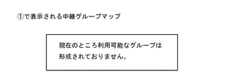
図11は、中継グループマップを示す。この時点では、未だ中継グループは形成されていないので、中継グループマップ表示部127、227、118、218は、表示すべき中継グループがないことを示すメッセージを表示する。
FIG. 11 shows a relay group map. At this time, since no relay group has been formed yet, the relay group
[ステップS3からステップS4までの処理の流れ]
以下の説明においては、中継サーバ12、22の相互間の通信は、SIPサーバ31により中継される。中継サーバ12(22)が中継サーバ22(12)に対してSIPサーバ31を介して通信を実行する方法について説明する。
[Processing flow from step S3 to step S4]
In the following description, communication between the
中継サーバ12(22)は、SIPサーバ31に対して、中継サーバ22(12)のアカウントが通信先として指定されたデータなどを送信する。SIPサーバ31は、中継サーバ12、22のアカウントを、各々、中継サーバ12、22のグローバルIPアドレスに対応付けている。SIPサーバ31は、中継サーバ22(12)のアカウントに基づいて、中継サーバ22(12)のグローバルIPアドレスを取得する。SIPサーバ31は、中継サーバ22(12)に対して、中継サーバ22(12)のグローバルIPアドレスが通信先として指定されたデータなどを送信する。
The relay server 12 (22) transmits, for example, data in which the account of the relay server 22 (12) is designated as a communication destination to the
中継サーバ12は、中継サーバ22に対して、中継通信システムのグループ構築を要求する(ステップS3:SetGroup())。制御部122は、中継グループ情報42を作成して、中継グループ情報格納部124に格納する。制御部222は、中継グループ情報42を作成して、中継グループ情報格納部224に格納する。
The
中継サーバ12は、中継サーバ22に対して、中継サーバ情報の交換を要求する(ステップS4:exchange(db))。中継サーバ12は、中継サーバ22に対して、中継サーバ情報51−1の複製を送信する。中継サーバ22は、中継サーバ12に対して、中継サーバ情報51−2の複製を送信する。
The
制御部122は、中継サーバ情報51−2の複製、中継サーバ情報51−1を合成することにより、中継サーバ情報52を作成して、中継サーバ情報格納部125に格納する。制御部222は、中継サーバ情報51−1の複製、中継サーバ情報51−2を合成することにより、中継サーバ情報52を作成して、中継サーバ情報格納部225に格納する。
The
制御部122は、クライアント端末情報62を作成して、クライアント端末情報格納部126に格納する。制御部222は、クライアント端末情報72を作成して、クライアント端末情報格納部226に格納する。クライアント端末情報62の作成処理および格納処理は、ステップS1において実行され、クライアント端末情報72の作成処理および格納処理は、ステップS2において実行される。
The
以上の処理の流れにより、中継サーバ12は、中継グループ情報42、中継サーバ情報52、クライアント端末情報62を保有する。中継サーバ22は、中継グループ情報42、中継サーバ情報52、クライアント端末情報72を保有する。中継グループ情報42、中継サーバ情報52は、中継サーバ12、22により共有されている。
Through the above processing flow, the
図12の1番目の枠内は、中継グループ情報42を示す。上位情報421は、上位にある中継グループについての情報である。「id」として、「20070402133100@relay−server−1.abc.net」が設定されている。「lastmod」として、「20070402133100」が設定されている。「name」として、「GROUP 1」が設定されている。しかし、中継サーバ12、22の相互間において、コネクションは確立されていない。そのため、中継グループ仮想アドレス情報は、いまだ記載されていない。
The first frame in FIG. 12 shows the relay group information 42. The
下位情報422は、下位にある中継サーバ12、22についての情報である。「id」として、「relay−server−1@abc.net」、「relay−server−2@abc.net」が設定されている。しかし、中継サーバ12、22の相互間において、仮想アドレスを利用したIP通信用のコネクションは確立されていない。そのため、中継サーバ仮想アドレス情報およびコネクション確立情報は、いまだ記載されていない。
The
図12の2番目の枠内は、中継サーバ情報52を示す。上位情報521−1、521−2は、各々、図10の上位情報511−1、511−2と同様である。下位情報522−1、522−2は、各々、図10の下位情報512−1、512−2と同様である。
The second frame in FIG. 12 shows the
図12の3番目の枠内は、クライアント端末情報62を示す。「div」として、「software」が設定されている。「group」として、「20070402133100@relay−server−1.abc.net」が設定されている。「id」として、「client−1@relay−server−1.abc.net」が設定されている。「name」として、「CLIENT 1」が設定されている。「pass」として、「client−1」が設定されている。
The third frame in FIG. 12 shows
クライアント端末アドレス情報621は、空欄になっている。クライアント端末有効期限情報622として、「0」が設定されている。クライアント端末ポート情報623は、空欄になっている。すなわち、クライアント端末11のユーザは、中継サーバ12にログオンしていない。
The client
図12の4番目の枠内は、クライアント端末情報72を示す。「div」として、「software」が設定されている。「group」として、「20070402133100@relay−server−1.abc.net」が設定されている。「id」として、「client−2@relay−server−2.abc.net」が設定されている。「name」として、「CLIENT 2」が設定されている。「pass」として、「client−2」が設定されている。
The fourth frame in FIG. 12 shows
クライアント端末アドレス情報721は、空欄になっている。クライアント端末有効期限情報722として、「0」が設定されている。クライアント端末ポート情報723は、空欄になっている。すなわち、クライアント端末21のユーザは、中継サーバ22にログオンしていない。
The client
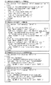
図13は、中継グループマップを示す。中継サーバ12の中継グループマップ表示部127および中継サーバ22の中継グループマップ表示部227は、中継グループ情報42および中継サーバ情報52を参照することにより、中継グループマップを表示する。
FIG. 13 shows a relay group map. The relay group map display unit 127 of the
中継サーバ12は、中継サーバ22に対して、中継通信システムのグループ構築を要求している。そのため、図11の中継グループマップが合成されて、図13の中継グループマップが表示されている。しかし、中継グループ情報42において、コネクション確立情報は、いまだ記載されていない。そのため、「中継サーバ12」および「中継サーバ22」の相互間において、「コネクション未確立」および傍らの破線が記載されている。
The
[ステップS5からステップS6までの処理の流れ]
中継サーバ12は、中継サーバ22に対して、呼制御を実行して(ステップS5:INVITE())、コネクション確立を要求する(ステップS6:connect())。制御部122は、中継グループ情報42を更新することにより、中継グループ情報43を作成して、中継グループ情報格納部124に格納する。中継サーバ12と中継サーバ22のコネクションが確立された時点で、中継サーバ12と中継サーバ22は、それぞれの仮想プライベートアドレスを割り当てる。制御部222は、中継グループ情報42を更新することにより、中継グループ情報43を作成して、中継グループ情報格納部224に格納する。制御部122は、中継サーバ情報52およびクライアント端末情報62を更新することはない。制御部222は、中継サーバ情報52およびクライアント端末情報72を更新することはない。
[Processing flow from step S5 to step S6]
The
以上の処理の流れにより、中継サーバ12は、中継グループ情報43、中継サーバ情報52、クライアント端末情報62を保有する。中継サーバ22は、中継グループ情報43、中継サーバ情報52、クライアント端末情報72を保有する。中継グループ情報43、中継サーバ情報52は、中継サーバ12、22により共有されている。
Through the above processing flow, the
図14の1番目の枠内は、中継グループ情報43を示す。更新部分を下線部により示す。中継サーバ12は、中継サーバ22に対して、仮想アドレスを利用したIP通信用のコネクションを確立している。
The first frame in FIG. 14 shows the
制御部122、222は、中継サーバ12、22の管理者が結んだ契約に基づいて、上位情報431の中継グループ仮想アドレス情報433を、「192.168.0.*」に設定している。中継通信システムにおいて、「*」は各装置に一意に設定される。
The
制御部122、222は、中継グループ仮想アドレス情報433に基づいて、下位情報432の中継サーバ12、22についての中継サーバ仮想アドレス情報434を、相互に異なる数値に設定している。制御部122は、「*」を「1」に設定して、中継サーバ12についての中継サーバ仮想アドレス情報434を、「192.168.0.1」に設定している。制御部222は、「*」を「2」に設定して、中継サーバ22についての中継サーバ仮想アドレス情報434を、「192.168.0.2」に設定している。
Based on the relay group
制御部122は、下位情報432の中継サーバ12についてのコネクション確立情報435を、「s1」に設定している。制御部222は、下位情報432の中継サーバ22についてのコネクション確立情報435を、「s2」に設定している。図7において、中継サーバ12、22の相互間の仮想アドレスを利用したIP通信用のコネクションのうち、中継サーバ12、22のソケットについて、「Transaction」は各々「s1」、「s2」に設定されている。
The
「groupID」は、コネクションが確立されている中継グループの識別情報を示しており、「20070402133100@relay−server−1.abc.net」に設定されている。「MediaSession」は、「socket」に設定されている。以上の2種類の情報は、図7および図9において同様である。 “GroupID” indicates identification information of the relay group with which the connection is established, and is set to “2007040402133100@relay-server-1.abc.net”. “MediaSession” is set to “socket”. The above two types of information are the same in FIG. 7 and FIG.
図14の2番目の枠内は、中継サーバ情報52を示す。ステップS5からステップS6までの処理の流れにおいては、クライアント端末11のユーザは、中継サーバ12にログオンしておらず、クライアント端末21のユーザは、中継サーバ22にログオンしていないため、中継サーバ情報52が更新されることはない。
The second frame in FIG. 14 shows the
図14の3番目の枠内は、クライアント端末情報62を示す。ステップS5からステップS6までの処理の流れにおいては、クライアント端末11のユーザは、中継サーバ12にログオンしていないため、クライアント端末情報62が更新されることはない。
The third frame in FIG. 14 shows
図14の4番目の枠内は、クライアント端末情報72を示す。ステップS5からステップS6までの処理の流れにおいては、クライアント端末21のユーザは、中継サーバ22にログオンしていないため、クライアント端末情報72が更新されることはない。
The fourth frame in FIG. 14 shows
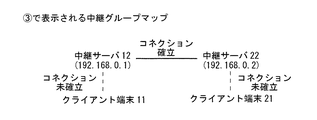
図15は、中継グループマップを示す。中継サーバ12の中継グループマップ表示部127および中継サーバ22の中継グループマップ表示部227は、中継グループ情報43および中継サーバ情報52を参照することにより、中継グループマップを表示する。
FIG. 15 shows a relay group map. The relay group map display unit 127 of the
中継サーバ12は、中継サーバ22に対して、呼制御を実行していて、仮想アドレスを利用したIP通信用のコネクション確立を要求している。そして、中継グループ情報43において、中継サーバ仮想アドレス情報434およびコネクション確立情報435が、すでに記載されている。そのため、中継サーバ12、22の仮想プライベートIPアドレスが記載されるに至った。そして、「中継サーバ12」および「中継サーバ22」の相互間において、「コネクション確立」および傍らの実線が記載されるに至った。
The
[ステップS7からステップS9までの処理の流れ]
図8を参照する。クライアント端末11のユーザは、クライアント端末11の識別情報として、「client−1@relay−server−1.abc.net」を入力して、クライアント端末11のパスワードとして、「client−1」を入力する。クライアント端末11のユーザは、中継サーバ12にログオンする(ステップS7:REGISTER(ID,PASS))。制御部122は、クライアント端末情報62を参照することにより、クライアント端末11のユーザの認証を実行する。
[Processing flow from step S7 to step S9]
Please refer to FIG. The user of the
制御部122は、クライアント端末11のユーザのログオンを受け付ける。制御部122は、中継サーバ情報52を更新することにより、中継サーバ情報54を作成して、中継サーバ情報格納部125に格納する。クライアント端末11が中継サーバ12にログオンした時点で、中継サーバ12はクライアント端末11の仮想プライベートアドレスを割り当てる。制御部122は、クライアント端末情報62を更新することにより、クライアント端末情報64を作成して、クライアント端末情報格納部126に格納する。制御部122は、中継グループ情報43を更新することはない。
The
クライアント端末11は、中継サーバ12に対して、中継グループ情報および中継サーバ情報の提供を要求する(ステップS8:get())。中継サーバ12は、クライアント端末11に対して、中継グループ情報43および中継サーバ情報54の複製を送信する。クライアント端末11は、中継グループ情報43を中継グループ情報格納部116に格納して、中継サーバ情報54を中継サーバ情報格納部117に格納する。
The
制御部122は、中継グループ情報43、中継サーバ情報54を参照することにより、中継サーバ情報52が中継サーバ情報54に更新されたことを通知すべき中継サーバを決定する。制御部122は、中継サーバ情報54の中継サーバ起動情報543−2が「active」である中継サーバ22を、通知すべき中継サーバとして決定する。
The
中継サーバ12は、中継サーバ22に対して、中継サーバ情報52が中継サーバ情報54に更新されたことを通知する(ステップS9:NOTIFY())。制御部222は、中継サーバ情報52を更新することにより、中継サーバ情報54を作成して、中継サーバ情報格納部225に格納する。
The
制御部222は、クライアント端末情報72を参照することにより、中継サーバ情報52が中継サーバ情報54に更新されたことを通知すべきクライアント端末を決定する。制御部222は、クライアント端末情報72のクライアント端末アドレス情報721が空欄であり、クライアント端末情報72のクライアント端末ポート情報723が空欄であるクライアント端末21を、通知すべきクライアント端末として決定することはない。
The
以上の処理の流れにより、中継サーバ12は、中継グループ情報43、中継サーバ情報54、クライアント端末情報64を保有する。中継サーバ22は、中継グループ情報43、中継サーバ情報54、クライアント端末情報72を保有する。クライアント端末11は、中継グループ情報43、中継サーバ情報54を保有する。中継グループ情報43、中継サーバ情報54は、中継サーバ12、22、クライアント端末11により共有されている。
Through the above processing flow, the
図16の1番目の枠内は、中継グループ情報43を示す。ステップS7からステップS9までの処理の流れにおいては、新たな中継サーバが中継通信システムに参加していないため、中継グループ情報43が更新されることはない。
The first frame in FIG. 16 shows the
図16の2番目の枠内は、中継サーバ情報54を示す。更新部分を下線部により示す。クライアント端末11のユーザは、中継サーバ12にログオンしている。そのため、下位情報542−1のクライアント端末サイト情報546−1は、「relay−server−1@abc.net」に確定されている。
The second frame in FIG. 16 shows the
制御部122は、「*」を「11」に設定して、下位情報542−1のクライアント端末11についてのクライアント端末仮想アドレス情報544−1を、「192.168.0.11」に設定している。ここで、当該仮想プライベートIPアドレスは、すでに設定されている仮想プライベートIPアドレスと重複しない。
The
制御部122は、下位情報542−1のクライアント端末11についてのコネクション確立情報545−1を、空欄に設定している。すなわち、クライアント端末11および中継サーバ12の相互間において、仮想アドレスを利用したIP通信用のコネクションはいまだ確立されていない。
The
図16の3番目の枠内は、クライアント端末情報64を示す。更新部分を下線部により示す。クライアント端末11のユーザは、中継サーバ12にログオンしている。そのため、クライアント端末アドレス情報641は、「192.168.10.2」に確定されている。ここで、クライアント端末11について、物理的なプライベートIPアドレス「192.168.10.2」は、仮想的なプライベートIPアドレス「192.168.0.11」と一致していない。また、クライアント端末有効期限情報642は、「1213935960484」に確定されている。さらに、クライアント端末ポート情報643は、「5070」に確定されている。
The third frame in FIG. 16 shows
図16の4番目の枠内は、クライアント端末情報72を示す。ステップS7からステップS9までの処理の流れにおいては、クライアント端末21のユーザが中継サーバ22にログオンしていないため、クライアント端末情報72が更新されることはない。
The fourth frame in FIG. 16 shows
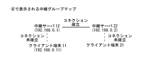
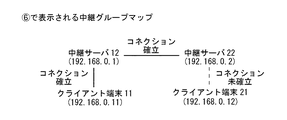
図17は、中継グループマップを示す。クライアント端末11の中継グループマップ表示部118、中継サーバ12の中継グループマップ表示部127、中継サーバ22の中継グループマップ表示部227は、中継グループ情報43および中継サーバ情報54を参照することにより、中継グループマップを表示する。
FIG. 17 shows a relay group map. The relay group
クライアント端末11のユーザは、中継サーバ12にログオンしている。そして、中継サーバ情報54において、クライアント端末仮想アドレス情報544−1が、すでに記載されている。そのため、クライアント端末11の仮想プライベートIPアドレスが記載されるに至った。しかし、中継サーバ情報54において、コネクション確立情報545−1が、いまだ記載されていない。そのため、「クライアント端末11」および「中継サーバ12」の相互間において、「コネクション確立」および傍らの実線が記載されていない。
The user of the
[ステップS10からステップS13までの処理の流れ]
クライアント端末21のユーザは、クライアント端末21の識別情報として、「client−2@relay−server−2.abc.net」を入力して、クライアント端末21のパスワードとして、「client−2」を入力する。クライアント端末21のユーザは、中継サーバ22にログオンする(ステップS10:REGISTER(ID,PASS))。制御部222は、クライアント端末情報72を参照することにより、クライアント端末21のユーザの認証を実行する。
[Processing flow from step S10 to step S13]
The user of the
制御部222は、クライアント端末21のユーザのログオンを受け付ける。制御部222は、中継サーバ情報54を更新することにより、中継サーバ情報55を作成して、中継サーバ情報格納部225に格納する。クライアント端末21が中継サーバ22にログオンした時点で、中継サーバ22はクライアント端末21の仮想プライベートアドレスを割り当てる。制御部222は、クライアント端末情報72を更新することにより、クライアント端末情報75を作成して、クライアント端末情報格納部226に格納する。制御部222は、中継グループ情報43を更新することはない。
The
クライアント端末21は、中継サーバ22に対して、中継グループ情報および中継サーバ情報の提供を要求する(ステップS11:get())。中継サーバ22は、クライアント端末21に対して、中継グループ情報43および中継サーバ情報55の複製を送信する。クライアント端末21は、中継グループ情報43を中継グループ情報格納部216に格納して、中継サーバ情報55を中継サーバ情報格納部217に格納する。
The
制御部222は、中継グループ情報43、中継サーバ情報55を参照することにより、中継サーバ情報54が中継サーバ情報55に更新されたことを通知すべき中継サーバを決定する。制御部222は、中継サーバ情報55の中継サーバ起動情報553−1が「active」である中継サーバ12を、通知すべき中継サーバとして決定する。
The
中継サーバ22は、中継サーバ12に対して、中継サーバ情報54が中継サーバ情報55に更新されたことを通知する(ステップS12:NOTIFY())。制御部122は、中継サーバ情報54を更新することにより、中継サーバ情報55を作成して、中継サーバ情報格納部125に格納する。
The
制御部122は、クライアント端末情報64を参照することにより、中継サーバ情報54が中継サーバ情報55に更新されたことを通知すべきクライアント端末を決定する。制御部122は、クライアント端末情報64のクライアント端末アドレス情報641が確定されていて、クライアント端末情報64のクライアント端末ポート情報643が確定されているクライアント端末11を、通知すべきクライアント端末として決定する。
The
中継サーバ12は、クライアント端末11に対して、中継サーバ情報54が中継サーバ情報55に更新されたことを通知する(ステップS13:NOTIFY())。制御部112は、中継サーバ情報54を更新することにより、中継サーバ情報55を作成して、中継サーバ情報格納部117に格納する。
The
以上の処理の流れにより、中継サーバ12は、中継グループ情報43、中継サーバ情報55、クライアント端末情報64を保有する。中継サーバ22は、中継グループ情報43、中継サーバ情報55、クライアント端末情報75を保有する。クライアント端末11は、中継グループ情報43、中継サーバ情報55を保有する。クライアント端末21は、中継グループ情報43、中継サーバ情報55を保有する。中継グループ情報43、中継サーバ情報55は、中継サーバ12、22、クライアント端末11、21により共有されている。
Through the above processing flow, the
図18の1番目の枠内は、中継グループ情報43を示す。ステップS10からステップS13までの処理の流れにおいては、新たな中継サーバが中継通信システムに参加していないため、中継グループ情報43が更新されることはない。
The first frame in FIG. 18 shows the
図18の2番目の枠内は、中継サーバ情報55を示す。更新部分を下線部により示す。クライアント端末21のユーザは、中継サーバ22にログオンしている。そのため、下位情報552−2のクライアント端末サイト情報556−2は、「relay−server−2@abc.net」に確定されている。
The second frame in FIG. 18 shows the
制御部222は、「*」を「12」に設定して、下位情報552−2のクライアント端末21についてのクライアント端末仮想アドレス情報554−2を、「192.168.0.12」に設定している。ここで、当該仮想プライベートIPアドレスは、すでに設定されている仮想プライベートIPアドレスと重複しない。
The
制御部222は、下位情報552−2のクライアント端末21についてのコネクション確立情報555−2を、空欄に設定している。すなわち、クライアント端末21および中継サーバ22の相互間において、仮想アドレスを利用したIP通信用のコネクションはいまだ確立されていない。
The
図18の3番目の枠内は、クライアント端末情報64を示す。ステップS10からステップS13までの処理の流れにおいては、クライアント端末11のユーザが中継サーバ12からログオフしていないため、クライアント端末情報64が更新されることはない。
The third frame in FIG. 18 shows
図18の4番目の枠内は、クライアント端末情報75を示す。更新部分を下線部により示す。クライアント端末21のユーザは、中継サーバ22にログオンしている。そのため、クライアント端末アドレス情報751は、「192.168.1.10」に確定されている。ここで、クライアント端末21について、物理的なプライベートIPアドレス「192.168.1.10」は、仮想的なプライベートIPアドレス「192.168.0.12」と一致していない。また、クライアント端末有効期限情報752は、「1213935978484」に確定されている。さらに、クライアント端末ポート情報753は、「5070」に確定されている。
The fourth frame in FIG. 18 shows
図19は、中継グループマップを示す。クライアント端末11の中継グループマップ表示部118、クライアント端末21の中継グループマップ表示部218、中継サーバ12の中継グループマップ表示部127、中継サーバ22の中継グループマップ表示部227は、中継グループ情報43および中継サーバ情報55を参照することにより、中継グループマップを表示する。
FIG. 19 shows a relay group map. The relay group
クライアント端末21のユーザは、中継サーバ22にログオンしている。そして、中継サーバ情報55において、クライアント端末仮想アドレス情報554−2が、すでに記載されている。そのため、クライアント端末21の仮想プライベートIPアドレスが記載されるに至った。しかし、中継サーバ情報55において、コネクション確立情報555−2が、いまだ記載されていない。そのため、「クライアント端末21」および「中継サーバ22」の相互間において、「コネクション確立」および傍らの実線が記載されていない。
The user of the
[ステップS14からステップS17までの処理の流れ]
図9を参照する。クライアント端末11は、中継サーバ12に対して、呼制御を実行して(ステップS14:INVITE())、仮想アドレスを利用したIP通信用のコネクションの確立を要求する(ステップS15:connect())。制御部122、112は、中継サーバ情報55を更新することにより、中継サーバ情報56を作成して、各々、中継サーバ情報格納部125、117に格納する。制御部122は、中継グループ情報43およびクライアント端末情報64を更新することはない。制御部112は、中継グループ情報43を更新することはない。
[Flow of processing from step S14 to step S17]
Please refer to FIG. The
ステップS16からステップS17までの処理の流れは、ステップS9、S12、S13と同様にして実行される。中継サーバ12は、中継サーバ22に対して、中継サーバ情報55が中継サーバ情報56に更新されたことを通知する(ステップS16:NOTIFY())。中継サーバ22は、クライアント端末21に対して、中継サーバ情報55が中継サーバ情報56に更新されたことを通知する(ステップS17:NOTIFY())。
The process flow from step S16 to step S17 is executed in the same manner as steps S9, S12, and S13. The
以上の処理の流れにより、中継サーバ12は、中継グループ情報43、中継サーバ情報56、クライアント端末情報64を保有する。中継サーバ22は、中継グループ情報43、中継サーバ情報56、クライアント端末情報75を保有する。クライアント端末11は、中継グループ情報43、中継サーバ情報56を保有する。クライアント端末21は、中継グループ情報43、中継サーバ情報56を保有する。中継グループ情報43、中継サーバ情報56は、中継サーバ12、22、クライアント端末11、21により共有されている。
Through the above processing flow, the
図20の1番目の枠内は、中継グループ情報43を示す。ステップS14からステップS17までの処理の流れにおいては、新たな中継サーバが中継通信システムに参加していないため、中継グループ情報43が更新されることはない。
The first frame in FIG. 20 shows the
図20の2番目の枠内は、中継サーバ情報56を示す。クライアント端末11は、中継サーバ12に対して、仮想アドレスを利用したIP通信用のコネクションを確立している。
The second frame in FIG. 20 shows the
制御部122、112は、下位情報562−1のコネクション確立情報565−1を、「c1」に設定している。図9において、クライアント端末11および中継サーバ12の相互間のコネクションのうち、クライアント端末11および中継サーバ12のソケットについて、「Transaction」は「c1」に設定されている。「groupID」および「MediaSession」は上述の通りである。
The
ここで、クライアント端末11および中継サーバ12の相互間の仮想アドレスを利用したIP通信用のコネクションにおける中継サーバ12のソケット、および、中継サーバ12および中継サーバ22の相互間の仮想アドレスを利用したIP通信用のコネクションにおける中継サーバ12のソケットは、相互に異なるソケットである。しかし、これらのソケットは、同一のgroupIDにより関連付けられる。
Here, the socket of the
図20の3番目の枠内は、クライアント端末情報64を示す。ステップS14からステップS17までの処理の流れにおいては、クライアント端末11のユーザが中継サーバ12からログオフしていないため、クライアント端末情報64が更新されることはない。
The third frame in FIG. 20 shows
図20の4番目の枠内は、クライアント端末情報75を示す。ステップS14からステップS17までの処理の流れにおいては、クライアント端末21のユーザが中継サーバ22からログオフしていないため、クライアント端末情報75が更新されることはない。
The fourth frame in FIG. 20 shows
図21は、中継グループマップを示す。クライアント端末11の中継グループマップ表示部118、クライアント端末21の中継グループマップ表示部218、中継サーバ12の中継グループマップ表示部127、中継サーバ22の中継グループマップ表示部227は、中継グループ情報43および中継サーバ情報56を参照することにより、中継グループマップを表示する。
FIG. 21 shows a relay group map. The relay group
クライアント端末11は、中継サーバ12に対して、仮想アドレスを利用したIP通信用のコネクションを確立している。そして、中継サーバ情報56において、コネクション確立情報565−1が、すでに記載されている。そのため、「クライアント端末11」および「中継サーバ12」の相互間において、「コネクション確立」および傍らの実線が記載されるに至った。
The
[ステップS18からステップS21までの処理の流れ]
クライアント端末21は、中継サーバ22に対して、呼制御を実行して(ステップS18:INVITE())、仮想アドレスを利用したIP通信用のコネクションの確立を要求する(ステップS19:connect())。制御部222、212は、中継サーバ情報56を更新することにより、中継サーバ情報57を作成して、各々、中継サーバ情報格納部225、217に格納する。制御部222は、中継グループ情報43およびクライアント端末情報75を更新することはない。制御部212は、中継グループ情報43を更新することはない。
[Flow of processing from step S18 to step S21]
The
ステップS20からステップS21までの処理の流れは、ステップS9、S12、S13と同様にして実行される。中継サーバ22は、中継サーバ12に対して、中継サーバ情報56が中継サーバ情報57に更新されたことを通知する(ステップS20:NOTIFY())。中継サーバ12は、クライアント端末11に対して、中継サーバ情報56が中継サーバ情報57に更新されたことを通知する(ステップS21:NOTIFY())。
The process flow from step S20 to step S21 is executed in the same manner as steps S9, S12, and S13. The
以上の処理の流れにより、中継サーバ12は、中継グループ情報43、中継サーバ情報57、クライアント端末情報64を保有する。中継サーバ22は、中継グループ情報43、中継サーバ情報57、クライアント端末情報75を保有する。クライアント端末11は、中継グループ情報43、中継サーバ情報57を保有する。クライアント端末21は、中継グループ情報43、中継サーバ情報57を保有する。中継グループ情報43、中継サーバ情報57は、中継サーバ12、22、クライアント端末11、21により共有されている。
Through the above processing flow, the
図22の1番目の枠内は、中継グループ情報43を示す。ステップS18からステップS21までの処理の流れにおいては、新たな中継サーバが中継通信システムに参加していないため、中継グループ情報43が更新されることはない。
The first frame in FIG. 22 shows the
図22の2番目の枠内は、中継サーバ情報57を示す。クライアント端末21は、中継サーバ22に対して、仮想アドレスを利用したIP通信用のコネクションを確立している。
The second frame in FIG. 22 shows the
制御部222、212は、下位情報572−2のコネクション確立情報575−2を、「c2」に設定している。図9において、クライアント端末21および中継サーバ22の相互間の仮想アドレスを利用したIP通信用のコネクションのうち、クライアント端末21および中継サーバ22のソケットについて、「Transaction」は「c2」に設定されている。「groupID」および「MediaSession」は上述の通りである。
The
ここで、クライアント端末21および中継サーバ22の相互間の仮想アドレスを利用したIP通信用のコネクションにおける中継サーバ22のソケット、および、中継サーバ12および中継サーバ22の相互間の仮想アドレスを利用したIP通信用のコネクションにおける中継サーバ22のソケットは、相互に異なるソケットである。しかし、これらのソケットは、同一のgroupIDにより関連付けられる。
Here, the socket of the
図22の3番目の枠内は、クライアント端末情報64を示す。ステップS18からステップS21までの処理の流れにおいては、クライアント端末11のユーザが中継サーバ12からログオフしていないため、クライアント端末情報64が更新されることはない。
The third frame in FIG. 22 shows
図22の4番目の枠内は、クライアント端末情報75を示す。ステップS18からステップS21までの処理の流れにおいては、クライアント端末21のユーザが中継サーバ22からログオフしていないため、クライアント端末情報75が更新されることはない。
The fourth frame in FIG. 22 shows
図23は、中継グループマップを示す。クライアント端末11の中継グループマップ表示部118、クライアント端末21の中継グループマップ表示部218、中継サーバ12の中継グループマップ表示部127、中継サーバ22の中継グループマップ表示部227は、中継グループ情報43および中継サーバ情報57を参照することにより、中継グループマップを表示する。
FIG. 23 shows a relay group map. The relay group
クライアント端末21は、中継サーバ22に対して、仮想アドレスを利用したIP通信用のコネクションを確立している。そして、中継サーバ情報57において、コネクション確立情報575−2が、すでに記載されている。そのため、「クライアント端末21」および「中継サーバ22」の相互間において、「コネクション確立」および傍らの実線が記載されるに至った。
The
{情報共有のまとめ}
中継通信システムにおいて、LANおよびクライアント端末の増減状態および接続状態が変化することがある。そこで、一の中継サーバは、状態変化を認識したときには、中継グループ情報、中継サーバ情報、クライアント端末情報を直ちに更新する。
{Summary of information sharing}
In a relay communication system, the increase / decrease state and connection state of LANs and client terminals may change. Therefore, when one relay server recognizes the state change, it immediately updates the relay group information, the relay server information, and the client terminal information.
そして、一の中継サーバは、中継グループ情報および中継サーバ情報に記載されている他の中継サーバに、中継グループ情報および中継サーバ情報が更新されたことを直ちに通知する。さらに、一の中継サーバは、クライアント端末情報に記載されているクライアント端末に、中継グループ情報および中継サーバ情報が更新されたことを直ちに通知する。 Then, the one relay server immediately notifies the other relay servers described in the relay group information and the relay server information that the relay group information and the relay server information are updated. Further, the one relay server immediately notifies the client terminal described in the client terminal information that the relay group information and the relay server information are updated.
しかし、一の中継サーバは、他の中継サーバが中継グループ情報および中継サーバ情報に記載されているとしても、他の中継サーバが未接続状態にあると判断したときには、他の中継サーバに直ちに通知することはない。さらに、一の中継サーバは、クライアント端末がクライアント端末情報に記載されているとしても、クライアント端末が未接続状態にあると判断したときには、クライアント端末に直ちに通知することはない。 However, if one relay server determines that another relay server is not connected even if the other relay server is described in the relay group information and relay server information, it immediately notifies the other relay server. Never do. Furthermore, even if the client terminal is described in the client terminal information, the one relay server does not immediately notify the client terminal when it is determined that the client terminal is not connected.
一の中継サーバの管理者は、他の中継サーバの管理者と交渉することにより、仮想プライベートIPアドレスを各装置に割り付ける方法を決定する。一の中継サーバは、他の中継サーバと通信することにより、各装置の仮想プライベートIPアドレスが重複しないように、自装置の仮想プライベートIPアドレスを決定する。中継サーバは、自装置にログオンするクライアント端末と通信することにより、各装置の仮想プライベートIPアドレスが重複しないように、クライアント端末の仮想プライベートIPアドレスを決定する。 The administrator of one relay server determines how to assign a virtual private IP address to each device by negotiating with the administrator of another relay server. One relay server determines the virtual private IP address of its own device by communicating with other relay servers so that the virtual private IP address of each device does not overlap. The relay server determines the virtual private IP address of the client terminal so that the virtual private IP address of each device does not overlap by communicating with the client terminal that logs on to the own device.
各装置の仮想プライベートIPアドレスについての情報は、中継グループ情報および中継サーバ情報に含まれる。各装置の仮想アドレスを利用したIP通信用のコネクション確立状態についての情報は、中継グループ情報および中継サーバ情報に含まれる。各装置のこれらの情報が変化したときには、中継グループ情報および中継サーバ情報が中継通信システム全体にわたって更新される。 Information about the virtual private IP address of each device is included in the relay group information and the relay server information. Information about the connection establishment state for IP communication using the virtual address of each device is included in the relay group information and the relay server information. When these pieces of information of each device change, the relay group information and the relay server information are updated throughout the relay communication system.
これにより、LANおよびクライアント端末の増減状態および接続状態についての情報は、中継通信システム全体としてリアルタイムに共有される。そして、各装置の仮想プライベートIPアドレスについての情報、および、各装置の仮想アドレスを利用したIP通信用のコネクション確立状態についての情報は、中継通信システム全体としてリアルタイムに共有される。さらに、以上に説明されたすべての情報は、各装置においてリアルタイムに表示される。 Thereby, the information about the increase / decrease state and connection state of the LAN and the client terminal is shared in real time as the entire relay communication system. Information on the virtual private IP address of each device and information on the connection establishment state for IP communication using the virtual address of each device are shared in real time as the entire relay communication system. Furthermore, all the information described above is displayed in real time on each device.
なお、上記の実施の形態においては、中継サーバ12、22間でコネクションが確立されたとき、あるいはクライアント端末11、21が中継サーバ12、22にログオンしたときに、中継サーバ12、22が各サーバや各端末に仮想プライベートアドレスを動的に割り当てるようにした。しかし、仮想アドレスを付与するタイミングはこれに限定されるものではない。たとえば、グループが形成された時点で、登録されている全てのクライアント端末に一括して仮想アドレスを割り当てるようにしてもよいし、中継サーバやクライアント端末を作成した時点で仮想アドレスを割り当ててもよい。その場合でもログオン状態をチェックすることで仮想アドレスを利用した通信の可否を判断できる。
In the above embodiment, when a connection is established between the
また、上記の実施の形態においては、全ての中継サーバ、全てのクライアント端末が仮想LANドライバを備え、仮想アドレスを利用しているが、一部のサーバやクライアント端末のみが仮想LANドラバイを備える構成であってもよい。仮想LANドライバを利用するWEBサーバが中継グループ内に存在してもよい。 In the above embodiment, all relay servers and all client terminals have virtual LAN drivers and use virtual addresses, but only some servers and client terminals have virtual LAN drives. It may be. A WEB server using a virtual LAN driver may exist in the relay group.
{データ送受信の流れ}
図24は、情報共有後におけるデータ送受信の流れを示す図である。情報共有後においては、図22に示した中継グループ情報43、中継サーバ情報57、クライアント端末情報64、75が格納されていて、図23に示した中継グループマップが表示されている。ウェブブラウザ113は、ウェブサーバ213に対して、コンテンツを要求する。ウェブサーバ213は、ウェブブラウザ113に対して、コンテンツを提供する。
{Flow of data transmission / reception}
FIG. 24 is a diagram showing a flow of data transmission / reception after information sharing. After information sharing, the
[ステップS22からステップS25までの処理の流れ]
図24を参照する。仮想LANドライバ114およびウェブブラウザ113は、コンテンツの送受信に先立ち起動する。仮想LANドライバ114は、中継サーバ情報格納部117に格納された中継サーバ情報57に基づいて、クライアント端末11の仮想プライベートIPアドレスとして「192.168.0.11」を取得する(ステップS22:open(192.168.0.11))。ウェブブラウザ113は、ステップS22と同様にして、クライアント端末11の仮想プライベートIPアドレスとして「192.168.0.11」を取得する(ステップS24:start(192.168.0.11))。
[Processing flow from step S22 to step S25]
Refer to FIG. The
仮想LANドライバ214およびウェブサーバ213は、コンテンツの送受信に先立ち起動する。仮想LANドライバ214は、中継サーバ情報格納部217に格納された中継サーバ情報57に基づいて、クライアント端末21の仮想プライベートIPアドレスとして「192.168.0.12」を取得する(ステップS23:open(192.168.0.12))。ウェブサーバ213は、ステップS23と同様にして、クライアント端末21の仮想プライベートIPアドレスとして「192.168.0.12」を取得する(ステップS25:start(192.168.0.12))。
The
[ステップS26の処理の流れ]
ウェブブラウザ113は、仮想LANドライバ114に対して、送信先の仮想プライベートIPアドレスが「192.168.0.12」である、コンテンツ要求情報を出力する(ステップS26:http(192.168.0.12))。
[Processing flow of step S26]
The
仮想LANドライバ114は、制御部112に対して、コンテンツ要求情報の通信パケットを出力する。送信先の仮想プライベートIPアドレスは「192.168.0.12」に設定されていて、送信元の仮想プライベートIPアドレスは「192.168.0.11」に設定されている(ステップS26.1:packet(192.168.0.12,192.168.0.11))。
The
制御部112は、中継サーバ情報格納部117に格納された中継サーバ情報57のうち、クライアント端末仮想アドレス情報574−2を参照することにより、送信先がLAN1になくWAN3を介したLAN2にあることを確認する。
The
クライアント端末11は、ステップS15で確立されて「groupID=20070402133100@relay−server−1.abc.net」に設定された仮想アドレスを利用したIP通信用のコネクションにおいて、「Transaction:c1」に設定された自装置のソケットに向けて、カプセル化したコンテンツ要求情報の通信パケットを出力する。クライアント端末11は、中継サーバ12に対して、コンテンツ要求情報の通信パケットを送信する(ステップS26.1.1:connection(packet))。
The
中継サーバ12は、クライアント端末11から通信パケットを受信する。制御部122は、中継サーバ情報格納部125に格納された中継サーバ情報57のうち、クライアント端末仮想アドレス情報574−2を参照することにより、送信先がLAN1になくWAN3を介したLAN2にあることを確認する。
The
中継サーバ12は、ステップS6で確立されて「groupID=20070402133100@relay−server−1.abc.net」に設定された仮想アドレスを利用したIP通信用のコネクションにおいて、「Transaction:s1」に設定された自装置のソケットに向けて、カプセル化したコンテンツ要求情報の通信パケットを出力する。中継サーバ12は、中継サーバ22に対して、コンテンツ要求情報の通信パケットを送信する(ステップS26.1.1.1:connection(packet))。
The
中継サーバ22は、中継サーバ12から通信パケットを受信する。制御部222は、中継サーバ情報格納部225に格納された中継サーバ情報57のうち、クライアント端末仮想アドレス情報574−2を参照することにより、送信先がWAN3を介したLAN1になくLAN2にあることを確認する。
The
中継サーバ22は、ステップS19で確立されて「groupID=20070402133100@relay−server−1.abc.net」に設定された仮想アドレスを利用したIP通信用のコネクションにおいて、「Transaction:c2」に設定された自装置のソケットに向けて、カプセル化したコンテンツ要求情報の通信パケットを出力する。中継サーバ22は、クライアント端末21に対して、コンテンツ要求情報の通信パケットを送信する(ステップS26.1.1.1.1:connection(packet))。
The
クライアント端末21は、中継サーバ22から通信パケットを受診する。制御部212は、仮想LANドライバ214に対して、コンテンツ要求情報の通信パケットを出力する(ステップS26.1.1.1.1.1:packet(192.168.0.12,192.168.0.11))。
The
仮想LANドライバ214は、ウェブサーバ213に対して、送信元の仮想プライベートIPアドレスが「192.168.0.11」である、コンテンツ要求情報を出力する(ステップS26.1.1.1.1.1.1:http(192.168.0.11))。以上の処理の流れにより、コンテンツの要求が終了する。
The
[ステップS27の処理の流れ]
ウェブサーバ213は、仮想LANドライバ214に対して、送信先の仮想プライベートIPアドレスが「192.168.0.11」である、コンテンツを出力する(ステップS27:http(192.168.0.11))。
[Processing flow of step S27]
The
仮想LANドライバ214は、制御部212に対して、コンテンツの通信パケットを出力する。送信先の仮想プライベートIPアドレスは「192.168.0.11」に設定されていて、送信元の仮想プライベートIPアドレスは「192.168.0.12」に設定されている(ステップS27.1:packet(192.168.0.11,192.168.0.12))。
The
制御部212は、中継サーバ情報格納部217に格納された中継サーバ情報57のうち、クライアント端末仮想アドレス情報574−1を参照することにより、送信先がLAN2になくWAN3を介したLAN1にあることを確認する。
The
クライアント端末21は、ステップS19で確立されて「groupID=20070402133100@relay−server−1.abc.net」に設定された仮想アドレスを利用したIP通信用のコネクションにおいて、「Transaction:c2」に設定された自装置のソケットに向けて、カプセル化したコンテンツの通信パケットを出力する。クライアント端末21は、中継サーバ22に対して、コンテンツの通信パケットを送信する(ステップS27.1.1:connection(packet))。
The
中継サーバ22は、クライアント端末21から通信パケットを受信する。制御部222は、中継サーバ情報格納部225に格納された中継サーバ情報57のうち、クライアント端末仮想アドレス情報574−1を参照することにより、送信先がLAN2になくWAN3を介したLAN1にあることを確認する。
The
中継サーバ22は、ステップS6で確立されて「groupID=20070402133100@relay−server−1.abc.net」に設定された仮想アドレスを利用したIP通信用のコネクションにおいて、「Transaction:s2」に設定された自装置のソケットに向けて、カプセル化したコンテンツの通信パケットを出力する。中継サーバ22は、中継サーバ12に対して、コンテンツの通信パケットを送信する(ステップS27.1.1.1:connection(packet))。
The
中継サーバ12は、中継サーバ22から通信パケットを受信する。制御部122は、中継サーバ情報格納部125に格納された中継サーバ情報57のうち、クライアント端末仮想アドレス情報574−1を参照することにより、送信先がWAN3を介したLAN2になくLAN1にあることを確認する。
The
中継サーバ12は、ステップS15で確立されて「groupID=20070402133100@relay−server−1.abc.net」に設定された仮想アドレスを利用したIP通信用のコネクションにおいて、「Transaction:c1」に設定された自装置のソケットに向けて、カプセル化したコンテンツの通信パケットを出力する。中継サーバ12は、クライアント端末11に対して、コンテンツの通信パケットを送信する(ステップS27.1.1.1.1:connection(packet))。
The
クライアント端末11は、中継サーバ12から通信パケットを受信する。制御部112は、仮想LANドライバ114に対して、コンテンツの通信パケットを出力する(ステップS27.1.1.1.1.1:packet(192.168.0.11,192.168.0.12))。
The
仮想LANドライバ114は、ウェブブラウザ113に対して、送信元の仮想プライベートIPアドレスが「192.168.0.12」である、コンテンツを出力する(ステップS27.1.1.1.1.1.1:http(192.168.0.12))。以上の処理の流れにより、コンテンツの提供が終了する。
The
{データ送受信のまとめ}
中継通信システムを構成する各装置は、仮想プライベートIPアドレスを割り付けられていて、相互間において仮想アドレスを利用したIP通信用のコネクションを確立している。中継通信システムを構成する各装置は、全装置の仮想プライベートIPアドレスおよび全装置の仮想アドレスを利用したIP通信用のコネクション確立についての情報を、中継通信システムの状態変化に対応してリアルタイムに共有している。
{Summary of data transmission and reception}
Each device constituting the relay communication system is assigned a virtual private IP address, and establishes a connection for IP communication using the virtual address between them. Each device that configures the relay communication system shares in real time information regarding the connection establishment for IP communication using the virtual private IP address of all devices and the virtual address of all devices in response to changes in the state of the relay communication system. is doing.
データ送信側は、データ受信側の仮想プライベートIPアドレスが送信先として指定されたデータを送信する。データ受信側は、データ送信側の仮想プライベートIPアドレスが送信元として指定されたデータを受信する。送信データの通信パケットは、遠隔のLANの相互間に介在するWANにおいて、カプセル化されている。 The data transmission side transmits data in which the virtual private IP address of the data reception side is designated as the transmission destination. The data reception side receives data in which the virtual private IP address of the data transmission side is designated as the transmission source. A communication packet of transmission data is encapsulated in a WAN interposed between remote LANs.
データ送受信に関与する各装置は、データ受信側の仮想プライベートIPアドレスを、中継サーバ仮想アドレス情報またはクライアント端末仮想アドレス情報と照合することにより、送信データの通信パケットをいずれの装置に転送するかを決定する。データ送受信に関与する各装置は、仮想アドレスを利用したIP通信用のコネクション確立情報を参照することにより、送信データの通信パケットをいずれのコネクションのソケットに出力するかを決定する。 Each device involved in data transmission / reception checks the data receiving side's virtual private IP address against the relay server virtual address information or the client terminal virtual address information to determine which device the communication packet of the transmission data is transferred to. decide. Each device involved in data transmission / reception refers to the connection establishment information for IP communication using a virtual address, and determines which connection socket to output a communication packet of transmission data to.
従来技術のVPNにおいては、各装置は仮想プライベートIPアドレスを割り付けられている。しかし、各装置は、全装置の仮想プライベートIPアドレスについての情報を共有していないうえに、全装置のコネクション確立についての情報をも共有していない。そのため、各装置がデータを送信するにあたり通信エラーが発生したときには、送信先として指定された仮想プライベートIPアドレスが存在しないのか、送信先として指定された装置がコネクションを確立していないのか、が不明確である問題点があった。 In the prior art VPN, each device is assigned a virtual private IP address. However, each device does not share information about virtual private IP addresses of all devices, and also does not share information about connection establishment of all devices. Therefore, when a communication error occurs when each device transmits data, it is unclear whether the virtual private IP address specified as the destination does not exist or whether the device specified as the destination has not established a connection. There was a clear problem.
本発明の中継通信システムにおいては、各装置は仮想プライベートIPアドレスを割り付けられている。さらに、各装置は、全装置の仮想プライベートIPアドレスについての情報を共有しているうえに、全装置のコネクション確立についての情報をも共有している。そのため、従来技術のVPNにおける問題点を解消できるうえに、中継通信システムの状態変化に対応して拡張性および柔軟性のある仮想ネットワークを構築できる。 In the relay communication system of the present invention, each device is assigned a virtual private IP address. Further, each device shares information about the virtual private IP address of all devices, and also shares information about connection establishment of all devices. Therefore, it is possible to solve the problems in the prior art VPN and to construct a virtual network with expandability and flexibility in response to a change in the state of the relay communication system.
1、2 LAN
3 WAN
11、21 クライアント端末
12、22 中継サーバ
31 SIPサーバ
111、211 インターフェース部
112、212 制御部
113 ウェブブラウザ
213 ウェブサーバ
114、214 仮想LANドライバ
115、215 データベース格納部
116、216 中継グループ情報格納部
117、217 中継サーバ情報格納部
118、218 中継グループマップ表示部
121、221 インターフェース部
122、222 制御部
123、223 データベース格納部
124、224 中継グループ情報格納部
125、225 中継サーバ情報格納部
126、226 クライアント端末情報格納部
127、227 中継グループマップ表示部
128、228 仮想LANドライバ
1, 2 LAN
3 WAN
11, 21
Claims (4)
前記第1ネットワークに接続される第1中継サーバと、
前記第2ネットワークに接続される第2中継サーバと、
を備える中継通信システムであって、
前記第1中継サーバと前記第2中継サーバとは、
前記第1中継サーバと前記第2中継サーバとが構成する中継グループと、前記中継グループで利用する仮想ネットワークアドレスと、を示す中継グループ情報を作成する中継グループ情報作成部、
を含み、
前記第1中継サーバは、
前記第1中継サーバの起動状態を示す第1中継サーバ起動情報と、前記第1中継サーバと前記第1ネットワークに接続される第1クライアント端末との間の接続状態を含め前記第1中継サーバに登録されている前記第1クライアント端末に関する第1クライアント端末登録情報と、を含む第1中継サーバ情報を作成する第1中継サーバ情報作成部、
を含み、
前記第2中継サーバは、
前記第2中継サーバの起動状態を示す第2中継サーバ起動情報と、前記第2中継サーバと前記第2ネットワークに接続される第2クライアント端末との間の接続状態を含め前記第2中継サーバに登録されている前記第2クライアント端末に関する第2クライアント端末登録情報と、を含む第2中継サーバ情報を作成する第2中継サーバ情報作成部、
を含み、
前記第1中継サーバと前記第2中継サーバとは、
前記第1中継サーバ情報と前記第2中継サーバ情報と、を含む中継サーバ情報と、前記中継グループ情報とを、前記第1中継サーバと前記第2中継サーバとの間で共有する中継サーバ間共有部と、
所定のタイミングで前記第1クライアント端末および前記第2クライアント端末に前記中継グループ内でユニークとなるよう管理された仮想ネットワークアドレスを動的に付与するとともに、付与した仮想ネットワークアドレスの情報を前記中継サーバ情報に登録する仮想アドレス管理部と、
を含み、
前記第1中継サーバは、
前記中継グループ情報と前記中継サーバ情報とを前記第1中継サーバと前記第1クライアント端末との間で共有する第1クライアント端末間共有部、
を含み、
前記第2中継サーバは、
前記中継グループ情報と前記中継サーバ情報とを前記第2中継サーバと前記第2クライアント端末との間で共有する第2クライアント端末間共有部、
を含むことを特徴とする中継通信システム。 A first network, a second network,
A first relay server connected to the first network;
A second relay server connected to the second network;
A relay communication system comprising:
The first relay server and the second relay server are:
A relay group information creating unit for creating relay group information indicating a relay group constituted by the first relay server and the second relay server and a virtual network address used in the relay group;
Including
The first relay server is
The first relay server includes first relay server activation information indicating an activation state of the first relay server, and a connection state between the first relay server and a first client terminal connected to the first network. A first relay server information creating unit that creates first relay server information including first client terminal registration information relating to the registered first client terminal;
Including
The second relay server is
The second relay server includes the second relay server activation information indicating the activation state of the second relay server and the connection state between the second relay server and the second client terminal connected to the second network. A second relay server information creating unit that creates second relay server information including second client terminal registration information related to the registered second client terminal;
Including
The first relay server and the second relay server are:
Inter-relay server sharing in which the relay server information including the first relay server information and the second relay server information and the relay group information are shared between the first relay server and the second relay server. And
A virtual network address managed to be unique within the relay group is dynamically assigned to the first client terminal and the second client terminal at a predetermined timing, and information on the assigned virtual network address is provided to the relay server. A virtual address management unit to be registered in the information;
Including
The first relay server is
A first inter-client-terminal sharing unit that shares the relay group information and the relay server information between the first relay server and the first client terminal;
Including
The second relay server is
A second inter-client-terminal sharing unit that shares the relay group information and the relay server information between the second relay server and the second client terminal;
A relay communication system comprising:
前記中継グループ情報は、
前記第1中継サーバと前記第2中継サーバがコネクションを確立しているかどうかについての中継サーバコネクション確立情報、
を含み、
前記第1中継サーバ情報は、
前記第1クライアント端末が前記第1中継サーバとコネクションを確立しているかどうかについての第1クライアント端末コネクション確立情報、
を含み、
前記第2中継サーバ情報は、
前記第2クライアント端末が前記第2中継サーバとコネクションを確立しているかどうかについての第2クライアント端末コネクション確立情報、
を含むことを特徴とする中継通信システム。 The relay communication system according to claim 1,
The relay group information is
Relay server connection establishment information as to whether the first relay server and the second relay server have established a connection;
Including
The first relay server information is
First client terminal connection establishment information as to whether or not the first client terminal has established a connection with the first relay server;
Including
The second relay server information is
Second client terminal connection establishment information as to whether the second client terminal has established a connection with the second relay server;
A relay communication system comprising:
前記第1中継サーバは、
前記中継グループ情報と前記中継サーバ情報とに基づいて選択された前記第2ネットワークの仮想ネットワークアドレスが通信先として指定された、前記第1中継サーバが中継する通信を、前記中継グループ情報と前記中継サーバ情報とに基づいて実行する通信実行部、
を含むことを特徴とする中継通信システム。 In the relay communication system according to claim 1 or 2,
The first relay server is
Communication relayed by the first relay server, in which the virtual network address of the second network selected based on the relay group information and the relay server information is designated as a communication destination, the relay group information and the relay A communication execution unit to be executed based on the server information,
A relay communication system comprising:
前記第1中継サーバと前記第1クライアント端末とは、
前記中継グループ情報と前記中継サーバ情報とに基づいて、現在の前記中継グループ内のコネクションの確立状況と仮想アドレスとを視覚的に表すマップを表示するマップ表示部、
を含むことを特徴とする中継通信システム。 The relay communication system according to any one of claims 1 to 3,
The first relay server and the first client terminal are:
Based on the relay group information and the relay server information, a map display unit that displays a map that visually represents a connection establishment status and a virtual address in the current relay group;
A relay communication system comprising:
Priority Applications (6)
| Application Number | Priority Date | Filing Date | Title |
|---|---|---|---|
| JP2008230229A JP4831148B2 (en) | 2008-09-08 | 2008-09-08 | Relay server, relay communication system |
| TW098128872A TWI455547B (en) | 2008-09-01 | 2009-08-27 | Relay server and relay communication system |
| PCT/JP2009/004254 WO2010023958A1 (en) | 2008-09-01 | 2009-08-31 | Relay server and relayed communication system |
| CN2009801340667A CN102138304B (en) | 2008-09-01 | 2009-08-31 | Relay server and relayed communication system |
| EP09809613.4A EP2323315B1 (en) | 2008-09-01 | 2009-08-31 | Relay communication system |
| US13/061,234 US8356116B2 (en) | 2008-09-01 | 2009-08-31 | Relay server and relay communication system |
Applications Claiming Priority (1)
| Application Number | Priority Date | Filing Date | Title |
|---|---|---|---|
| JP2008230229A JP4831148B2 (en) | 2008-09-08 | 2008-09-08 | Relay server, relay communication system |
Publications (2)
| Publication Number | Publication Date |
|---|---|
| JP2010068051A true JP2010068051A (en) | 2010-03-25 |
| JP4831148B2 JP4831148B2 (en) | 2011-12-07 |
Family
ID=42193282
Family Applications (1)
| Application Number | Title | Priority Date | Filing Date |
|---|---|---|---|
| JP2008230229A Active JP4831148B2 (en) | 2008-09-01 | 2008-09-08 | Relay server, relay communication system |
Country Status (1)
| Country | Link |
|---|---|
| JP (1) | JP4831148B2 (en) |
Cited By (4)
| Publication number | Priority date | Publication date | Assignee | Title |
|---|---|---|---|---|
| WO2012081303A1 (en) * | 2010-12-16 | 2012-06-21 | 村田機械株式会社 | Relay communication system and relay servers |
| WO2012081304A1 (en) * | 2010-12-16 | 2012-06-21 | 村田機械株式会社 | Relay communication system and relay servers |
| WO2012081305A1 (en) * | 2010-12-16 | 2012-06-21 | 村田機械株式会社 | Relay communication system and relay servers |
| JP2013141072A (en) * | 2011-12-28 | 2013-07-18 | Murata Mach Ltd | Relay server |
Citations (3)
| Publication number | Priority date | Publication date | Assignee | Title |
|---|---|---|---|---|
| JP2005027040A (en) * | 2003-07-02 | 2005-01-27 | Ricoh Co Ltd | Monitoring method, program and centralized monitoring program |
| JP2008098881A (en) * | 2006-10-11 | 2008-04-24 | Murata Mach Ltd | Relay server |
| JP2008129991A (en) * | 2006-11-24 | 2008-06-05 | Murata Mach Ltd | Relay server and relay communication system |
-
2008
- 2008-09-08 JP JP2008230229A patent/JP4831148B2/en active Active
Patent Citations (3)
| Publication number | Priority date | Publication date | Assignee | Title |
|---|---|---|---|---|
| JP2005027040A (en) * | 2003-07-02 | 2005-01-27 | Ricoh Co Ltd | Monitoring method, program and centralized monitoring program |
| JP2008098881A (en) * | 2006-10-11 | 2008-04-24 | Murata Mach Ltd | Relay server |
| JP2008129991A (en) * | 2006-11-24 | 2008-06-05 | Murata Mach Ltd | Relay server and relay communication system |
Cited By (15)
| Publication number | Priority date | Publication date | Assignee | Title |
|---|---|---|---|---|
| KR101406854B1 (en) | 2010-12-16 | 2014-06-13 | 무라다기카이가부시끼가이샤 | Relay communication system and relay servers |
| KR101406852B1 (en) | 2010-12-16 | 2014-06-13 | 무라다기카이가부시끼가이샤 | Relay communication system and relay servers |
| WO2012081305A1 (en) * | 2010-12-16 | 2012-06-21 | 村田機械株式会社 | Relay communication system and relay servers |
| JP2012129830A (en) * | 2010-12-16 | 2012-07-05 | Murata Mach Ltd | Relay communication system and relay server |
| JP2012129831A (en) * | 2010-12-16 | 2012-07-05 | Murata Mach Ltd | Relay communication system and relay server |
| JP2012129832A (en) * | 2010-12-16 | 2012-07-05 | Murata Mach Ltd | Relay communication system and relay server |
| WO2012081304A1 (en) * | 2010-12-16 | 2012-06-21 | 村田機械株式会社 | Relay communication system and relay servers |
| CN103262476A (en) * | 2010-12-16 | 2013-08-21 | 村田机械株式会社 | Relay communication system and relay servers |
| US9380130B2 (en) | 2010-12-16 | 2016-06-28 | Murata Machinery, Ltd. | Relay communication system and relay servers |
| WO2012081303A1 (en) * | 2010-12-16 | 2012-06-21 | 村田機械株式会社 | Relay communication system and relay servers |
| KR101446974B1 (en) | 2010-12-16 | 2014-10-06 | 무라다기카이가부시끼가이샤 | Relay communication system and relay servers |
| US9037731B2 (en) | 2010-12-16 | 2015-05-19 | Murata Machinery, Ltd. | Relay communication system and relay servers |
| CN103262476B (en) * | 2010-12-16 | 2016-01-20 | 村田机械株式会社 | Relay communications system and Relay Server |
| US9319484B2 (en) | 2010-12-16 | 2016-04-19 | Murata Machinery, Ltd. | Relay communication system and relay servers |
| JP2013141072A (en) * | 2011-12-28 | 2013-07-18 | Murata Mach Ltd | Relay server |
Also Published As
| Publication number | Publication date |
|---|---|
| JP4831148B2 (en) | 2011-12-07 |
Similar Documents
| Publication | Publication Date | Title |
|---|---|---|
| WO2010023958A1 (en) | Relay server and relayed communication system | |
| EP3834396B1 (en) | User datagram protocol tunneling in distributed application instances | |
| JP5569697B2 (en) | Relay server and relay communication system | |
| EP2408153B1 (en) | First relay server and second relay server | |
| JP4831148B2 (en) | Relay server, relay communication system | |
| US20120185603A1 (en) | Relay server and relay communication system | |
| US9521012B2 (en) | Relay server and relay communication system | |
| SG190809A1 (en) | Relay server and relay communication system | |
| US9197557B2 (en) | Relay server and relay communication system | |
| JP4831145B2 (en) | Relay server and relay communication system | |
| JP4803229B2 (en) | Relay server, relay communication system | |
| JP5012738B2 (en) | Relay server, relay communication system | |
| WO2012081303A1 (en) | Relay communication system and relay servers | |
| JP5458610B2 (en) | Relay communication system | |
| JP4798197B2 (en) | Relay server, relay communication system | |
| JP7230593B2 (en) | Relay device and program | |
| JP5402181B2 (en) | Relay communication system | |
| JP2023538930A (en) | High availability network address translation | |
| JP5633693B2 (en) | Relay server and relay communication system | |
| JP5875507B2 (en) | Relay device, program, information processing method, and information processing device | |
| JP2010245982A (en) | Relay communication system | |
| JP2016096578A (en) | Relay device, information processing method, and program | |
| JP2012109874A (en) | Relay server and relay communication system | |
| JP2010157856A (en) | Vpn connection device, packet control method, and program |
Legal Events
| Date | Code | Title | Description |
|---|---|---|---|
| A621 | Written request for application examination |
Free format text: JAPANESE INTERMEDIATE CODE: A621 Effective date: 20110617 |
|
| A871 | Explanation of circumstances concerning accelerated examination |
Free format text: JAPANESE INTERMEDIATE CODE: A871 Effective date: 20110812 |
|
| TRDD | Decision of grant or rejection written | ||
| A975 | Report on accelerated examination |
Free format text: JAPANESE INTERMEDIATE CODE: A971005 Effective date: 20110818 |
|
| A01 | Written decision to grant a patent or to grant a registration (utility model) |
Free format text: JAPANESE INTERMEDIATE CODE: A01 Effective date: 20110823 |
|
| A01 | Written decision to grant a patent or to grant a registration (utility model) |
Free format text: JAPANESE INTERMEDIATE CODE: A01 |
|
| A61 | First payment of annual fees (during grant procedure) |
Free format text: JAPANESE INTERMEDIATE CODE: A61 Effective date: 20110905 |
|
| R150 | Certificate of patent or registration of utility model |
Ref document number: 4831148 Country of ref document: JP Free format text: JAPANESE INTERMEDIATE CODE: R150 Free format text: JAPANESE INTERMEDIATE CODE: R150 |
|
| FPAY | Renewal fee payment (event date is renewal date of database) |
Free format text: PAYMENT UNTIL: 20140930 Year of fee payment: 3 |
|
| R250 | Receipt of annual fees |
Free format text: JAPANESE INTERMEDIATE CODE: R250 |
|
| R250 | Receipt of annual fees |
Free format text: JAPANESE INTERMEDIATE CODE: R250 |
|
| R250 | Receipt of annual fees |
Free format text: JAPANESE INTERMEDIATE CODE: R250 |
|
| R250 | Receipt of annual fees |
Free format text: JAPANESE INTERMEDIATE CODE: R250 |
|
| R250 | Receipt of annual fees |
Free format text: JAPANESE INTERMEDIATE CODE: R250 |
|
| R250 | Receipt of annual fees |
Free format text: JAPANESE INTERMEDIATE CODE: R250 |
|
| R250 | Receipt of annual fees |
Free format text: JAPANESE INTERMEDIATE CODE: R250 |
|
| R250 | Receipt of annual fees |
Free format text: JAPANESE INTERMEDIATE CODE: R250 |
|
| R250 | Receipt of annual fees |
Free format text: JAPANESE INTERMEDIATE CODE: R250 |
|
| R250 | Receipt of annual fees |
Free format text: JAPANESE INTERMEDIATE CODE: R250 |