JP2010067426A - L-type coaxial connector - Google Patents

L-type coaxial connector Download PDF

Info

Publication number
JP2010067426A
JP2010067426A JP2008231758A JP2008231758A JP2010067426A JP 2010067426 A JP2010067426 A JP 2010067426A JP 2008231758 A JP2008231758 A JP 2008231758A JP 2008231758 A JP2008231758 A JP 2008231758A JP 2010067426 A JP2010067426 A JP 2010067426A
Authority
JP
Japan
Prior art keywords
bushing
coaxial connector
housing
opening
caulking
Prior art date
Legal status (The legal status is an assumption and is not a legal conclusion. Google has not performed a legal analysis and makes no representation as to the accuracy of the status listed.)
Granted
Application number
JP2008231758A
Other languages
Japanese (ja)
Other versions
JP4720881B2 (en
Inventor
Katsumi Kozai
克己 幸西
Susumu Hashimoto
進 橋本
Current Assignee (The listed assignees may be inaccurate. Google has not performed a legal analysis and makes no representation or warranty as to the accuracy of the list.)
Murata Manufacturing Co Ltd
Original Assignee
Murata Manufacturing Co Ltd
Priority date (The priority date is an assumption and is not a legal conclusion. Google has not performed a legal analysis and makes no representation as to the accuracy of the date listed.)
Filing date
Publication date
Application filed by Murata Manufacturing Co Ltd filed Critical Murata Manufacturing Co Ltd
Priority to JP2008231758A priority Critical patent/JP4720881B2/en
Priority to TW098126893A priority patent/TWI382607B/en
Priority to US12/544,417 priority patent/US8047871B2/en
Priority to KR1020090084934A priority patent/KR101041318B1/en
Priority to CN2009101734139A priority patent/CN101673909B/en
Priority to EP09252155.8A priority patent/EP2175524B1/en
Publication of JP2010067426A publication Critical patent/JP2010067426A/en
Application granted granted Critical
Publication of JP4720881B2 publication Critical patent/JP4720881B2/en
Active legal-status Critical Current
Anticipated expiration legal-status Critical

Links

Images

Classifications

    • HELECTRICITY
    • H01ELECTRIC ELEMENTS
    • H01RELECTRICALLY-CONDUCTIVE CONNECTIONS; STRUCTURAL ASSOCIATIONS OF A PLURALITY OF MUTUALLY-INSULATED ELECTRICAL CONNECTING ELEMENTS; COUPLING DEVICES; CURRENT COLLECTORS
    • H01R9/00Structural associations of a plurality of mutually-insulated electrical connecting elements, e.g. terminal strips or terminal blocks; Terminals or binding posts mounted upon a base or in a case; Bases therefor
    • H01R9/03Connectors arranged to contact a plurality of the conductors of a multiconductor cable, e.g. tapping connections
    • H01R9/05Connectors arranged to contact a plurality of the conductors of a multiconductor cable, e.g. tapping connections for coaxial cables
    • H01R9/0518Connection to outer conductor by crimping or by crimping ferrule
    • HELECTRICITY
    • H01ELECTRIC ELEMENTS
    • H01RELECTRICALLY-CONDUCTIVE CONNECTIONS; STRUCTURAL ASSOCIATIONS OF A PLURALITY OF MUTUALLY-INSULATED ELECTRICAL CONNECTING ELEMENTS; COUPLING DEVICES; CURRENT COLLECTORS
    • H01R13/00Details of coupling devices of the kinds covered by groups H01R12/70 or H01R24/00 - H01R33/00
    • H01R13/46Bases; Cases
    • H01R13/502Bases; Cases composed of different pieces
    • H01R13/506Bases; Cases composed of different pieces assembled by snap action of the parts
    • HELECTRICITY
    • H01ELECTRIC ELEMENTS
    • H01RELECTRICALLY-CONDUCTIVE CONNECTIONS; STRUCTURAL ASSOCIATIONS OF A PLURALITY OF MUTUALLY-INSULATED ELECTRICAL CONNECTING ELEMENTS; COUPLING DEVICES; CURRENT COLLECTORS
    • H01R2103/00Two poles
    • HELECTRICITY
    • H01ELECTRIC ELEMENTS
    • H01RELECTRICALLY-CONDUCTIVE CONNECTIONS; STRUCTURAL ASSOCIATIONS OF A PLURALITY OF MUTUALLY-INSULATED ELECTRICAL CONNECTING ELEMENTS; COUPLING DEVICES; CURRENT COLLECTORS
    • H01R24/00Two-part coupling devices, or either of their cooperating parts, characterised by their overall structure
    • H01R24/38Two-part coupling devices, or either of their cooperating parts, characterised by their overall structure having concentrically or coaxially arranged contacts
    • H01R24/40Two-part coupling devices, or either of their cooperating parts, characterised by their overall structure having concentrically or coaxially arranged contacts specially adapted for high frequency
    • H01R24/54Intermediate parts, e.g. adapters, splitters or elbows
    • H01R24/545Elbows

Landscapes

  • Coupling Device And Connection With Printed Circuit (AREA)

Abstract

<P>PROBLEM TO BE SOLVED: To provide an L-type coaxial connector which can be fabricated at a low cost. <P>SOLUTION: A housing 12 has a cylindrical part 20 which has an opening and contacts an exterior conductor of a receptacle inserted from the opening, and a rear face part 21 which is connected to the cylindrical part 20 and covers the opening. The housing is fabricated with a sheet of metal plate. In a bushing 14, the diameter of a part housed in the cylindrical part 20 has a dimension of the diameter or less of the opening. The housing 12 furthermore includes a caulking part 26 which exists extended from the rear face part 21, and which fixes the bushing 14 to the housing 12 by means that the caulking part 26 is folded back to oppose to the rear face part 21 by pinching the bushing 14. <P>COPYRIGHT: (C)2010,JPO&INPIT

Description

本発明は、L型同軸コネクタに関し、より特定的には、中心導体及び外導体を有するレセプタクルに着脱可能なL型同軸コネクタに関する。   The present invention relates to an L-shaped coaxial connector, and more particularly to an L-shaped coaxial connector that can be attached to and detached from a receptacle having a center conductor and an outer conductor.

従来のL型同軸コネクタとしては、例えば、特許文献1に記載の同軸コネクタが知られている。図17は、特許文献1に記載の同軸コネクタ210及びレセプタクル230の分解斜視図である。   As a conventional L-shaped coaxial connector, for example, a coaxial connector described in Patent Document 1 is known. FIG. 17 is an exploded perspective view of the coaxial connector 210 and the receptacle 230 described in Patent Document 1.

同軸コネクタ210は、ハウジング212、ブッシング214、ソケット216及び絶縁シート218により構成され、同軸ケーブル220の先端に取り付けられると共に、レセプタクル230に対して着脱される。同軸ケーブル220は、外導体222及び中心導体224を有している。また、レセプタクル230は、外部導体232及び中心導体234により構成されている。   The coaxial connector 210 includes a housing 212, a bushing 214, a socket 216, and an insulating sheet 218. The coaxial connector 210 is attached to the distal end of the coaxial cable 220 and is attached to and detached from the receptacle 230. The coaxial cable 220 has an outer conductor 222 and a center conductor 224. The receptacle 230 is composed of an outer conductor 232 and a center conductor 234.

ハウジング212は、図17に示すように、円筒部226、蓋部228及びかしめ部229により構成されており、同軸ケーブル220の外導体222と接続される。ブッシング214は、絶縁性材料により作製され、図17に示すように、ハウジング212の円筒部226内に取り付けられる。ソケット216は、ブッシング214に取り付けられると共に、同軸ケーブル220の中心導体224と接続される。絶縁シート218は、ソケット216と蓋部228との間に設けられる。ブッシング214、ソケット216及び絶縁シート218が、ハウジング212に対して取り付けられると、蓋部228が閉じられると共に、かしめ部229がかしめられる。これにより、円筒部226、蓋部228及び同軸ケーブル220が固定される。   As illustrated in FIG. 17, the housing 212 includes a cylindrical portion 226, a lid portion 228, and a caulking portion 229, and is connected to the outer conductor 222 of the coaxial cable 220. The bushing 214 is made of an insulating material, and is attached in the cylindrical portion 226 of the housing 212 as shown in FIG. The socket 216 is attached to the bushing 214 and connected to the central conductor 224 of the coaxial cable 220. The insulating sheet 218 is provided between the socket 216 and the lid 228. When the bushing 214, the socket 216, and the insulating sheet 218 are attached to the housing 212, the lid portion 228 is closed and the caulking portion 229 is caulked. Thereby, the cylindrical part 226, the cover part 228, and the coaxial cable 220 are fixed.

前記のように構成された同軸コネクタ210は、レセプタクル230に装着される。具体的には、外部導体232が、円筒部226内に挿入されることにより、該円筒部226と接触すると共に、中心導体234が、ソケット216に挿入される。これにより、同軸ケーブル220の外導体222とレセプタクル230の外部導体232とが電気的に接続され、同軸ケーブル220の中心導体224とレセプタクル230の中心導体234とが電気的に接続される。   The coaxial connector 210 configured as described above is attached to the receptacle 230. Specifically, the outer conductor 232 is inserted into the cylindrical portion 226 so as to come into contact with the cylindrical portion 226 and the center conductor 234 is inserted into the socket 216. Thereby, the outer conductor 222 of the coaxial cable 220 and the outer conductor 232 of the receptacle 230 are electrically connected, and the center conductor 224 of the coaxial cable 220 and the center conductor 234 of the receptacle 230 are electrically connected.

ところで、特許文献1に記載の同軸コネクタ210では、以下に説明するように、安価に作製することが困難であった。より詳細には、1枚の金属板に対してプレス加工等を施すことによりハウジング212を作製する。そして、ブッシング214、ソケット216及び絶縁シート218を、図17の状態のハウジング212に対して取り付けて、蓋部228を閉じると共に、かしめ部229をかしめる。   Incidentally, the coaxial connector 210 described in Patent Document 1 is difficult to manufacture at a low cost, as will be described below. More specifically, the housing 212 is manufactured by performing press working or the like on one metal plate. Then, the bushing 214, the socket 216, and the insulating sheet 218 are attached to the housing 212 in the state of FIG. 17, and the lid portion 228 is closed and the caulking portion 229 is caulked.

以上のように、同軸コネクタ210の製造では、図17の状態のハウジング212を作製する工程と、蓋部228を閉じる工程との間において、ブッシング214、ソケット216及び絶縁シート218を取り付ける工程を行っている。ここで、同軸コネクタ210の製造コスト低減の観点からは、ハウジング212の加工は、1つのライン上において連続して行われることが好ましい。したがって、図17の状態のハウジング212を作製する工程と、蓋部228を閉じる工程とは、1つのライン上において連続して行われることが好ましい。   As described above, in the manufacture of the coaxial connector 210, the step of attaching the bushing 214, the socket 216, and the insulating sheet 218 is performed between the step of manufacturing the housing 212 in the state of FIG. 17 and the step of closing the lid 228. ing. Here, from the viewpoint of reducing the manufacturing cost of the coaxial connector 210, it is preferable that the processing of the housing 212 is continuously performed on one line. Therefore, it is preferable that the step of manufacturing the housing 212 in the state of FIG. 17 and the step of closing the lid 228 are continuously performed on one line.

しかしながら、同軸コネクタ210において、図17の状態のハウジング212を作製した直後に、蓋部228を閉じてしまうと、ブッシング214、ソケット216及び絶縁シート218を取り付けることができない。故に、同軸コネクタ210を安価に作製することは困難であった。
特開2006−228614号公報
However, in the coaxial connector 210, the bushing 214, the socket 216, and the insulating sheet 218 cannot be attached if the lid 228 is closed immediately after the housing 212 in the state shown in FIG. Therefore, it has been difficult to manufacture the coaxial connector 210 at a low cost.
JP 2006-228614 A

そこで、本発明の目的は、安価に作製可能なL型同軸コネクタを提供することである。   Therefore, an object of the present invention is to provide an L-shaped coaxial connector that can be manufactured at low cost.

本発明の一形態であるL型同軸コネクタは、中心導体及び外部導体を有するレセプタクルに着脱可能なL型同軸コネクタにおいて、第1の開口及び第2の開口を有していると共に、該第1の開口から挿入される前記外部導体と接触する円筒部、及び、該円筒部に接続されていると共に、該第2の開口を覆っている背面部を有しており、1枚の金属板により作製されているハウジングと、前記ハウジングに取り付けられているブッシングと、前記ブッシングに取り付けられ、かつ、該ブッシングにより前記ハウジングと絶縁されているソケットであって、前記中心導体と接続されるソケットと、を備え、前記ブッシングにおいて前記円筒部に収まっている部分の径は、前記第1の開口の径以下の大きさを有しており、前記ハウジングは、前記背面部から延在しているかしめ部であって、前記ブッシングを挟んで該背面部と対向するように折り曲げられることにより、該ブッシングを前記ハウジングに固定しているかしめ部を、更に含んでいること、を特徴とする。   An L-shaped coaxial connector according to an embodiment of the present invention is an L-shaped coaxial connector that can be attached to and detached from a receptacle having a center conductor and an outer conductor, and has a first opening and a second opening. A cylindrical portion that comes into contact with the outer conductor inserted from the opening, and a back surface portion that is connected to the cylindrical portion and covers the second opening. A fabricated housing, a bushing attached to the housing, a socket attached to the bushing and insulated from the housing by the bushing, the socket connected to the central conductor; A diameter of a portion of the bushing that is accommodated in the cylindrical portion is equal to or smaller than a diameter of the first opening. A caulking portion extending from the portion, and further includes a caulking portion that is fixed to the housing by being bent so as to face the back surface with the bushing interposed therebetween. It is characterized by.

本発明によれば、安価に作製可能なL型同軸コネクタを得ることができる。   According to the present invention, an L-shaped coaxial connector that can be manufactured at low cost can be obtained.

以下に、本発明の一実施形態に係るL型同軸コネクタについて、図面を参照して説明する。   Hereinafter, an L-shaped coaxial connector according to an embodiment of the present invention will be described with reference to the drawings.

(L型同軸コネクタの構成)
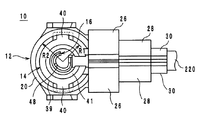
図1は、本発明の一実施形態に係るL型同軸コネクタ10の外観斜視図である。図2は、L型同軸コネクタ10の分解斜視図である。図3は、L型同軸コネクタ10の断面構造図である。図4は、L型同軸コネクタ10のハウジング12の組立て途中における斜視図である。図5は、L型同軸コネクタ10を平面視した図である。図1ないし図3(特に、図2参照)において、ハウジング12、ブッシング14及びソケット16が重ねられる方向をz軸方向とする。z軸方向の正方向は、ハウジング12からソケット16へと向かう方向である。また、同軸ケーブル220が延在している方向をx軸方向とし、x軸方向とz軸方向に直交する方向をy軸方向とする。x軸方向の正方向は、同軸ケーブル220からソケット16へと向かう方向である。
(Configuration of L-type coaxial connector)
FIG. 1 is an external perspective view of an L-shaped coaxial connector 10 according to an embodiment of the present invention. FIG. 2 is an exploded perspective view of the L-shaped coaxial connector 10. FIG. 3 is a cross-sectional structure diagram of the L-shaped coaxial connector 10. FIG. 4 is a perspective view of the L-shaped coaxial connector 10 during the assembly of the housing 12. FIG. 5 is a plan view of the L-shaped coaxial connector 10. 1 to 3 (see FIG. 2 in particular), a direction in which the housing 12, the bushing 14, and the socket 16 are overlapped is defined as a z-axis direction. The positive direction in the z-axis direction is a direction from the housing 12 toward the socket 16. The direction in which the coaxial cable 220 extends is defined as the x-axis direction, and the direction orthogonal to the x-axis direction and the z-axis direction is defined as the y-axis direction. The positive direction in the x-axis direction is a direction from the coaxial cable 220 toward the socket 16.

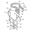
L型同軸コネクタ10は、図1及び図2に示すように、ハウジング12、ブッシング14及びソケット16により構成されており、同軸ケーブル220の先端に取り付けて用いられる。同軸ケーブル220は、絶縁膜221、外導体222、絶縁膜223及び中心導体224により構成されている。また、L型同軸コネクタ10は、図3(a)及び図3(b)に示すように、外部導体232及び中心導体234を有する示したレセプタクル230(外観斜視図については図17参照)に対して、着脱可能である。   As shown in FIGS. 1 and 2, the L-shaped coaxial connector 10 includes a housing 12, a bushing 14, and a socket 16, and is used by being attached to the tip of a coaxial cable 220. The coaxial cable 220 includes an insulating film 221, an outer conductor 222, an insulating film 223, and a center conductor 224. Further, as shown in FIGS. 3A and 3B, the L-shaped coaxial connector 10 has a receptacle 230 having an outer conductor 232 and a center conductor 234 (see FIG. 17 for an external perspective view). It is detachable.

ハウジング12は、1枚の金属板(例えば、ばね用りん青銅)により作製され、図2及び図4に示すように、円筒部20、背面部21、固定部24及びかしめ部26,28,30により構成されている。円筒部20は、一部(x軸方向の負方向側の部分)が切り欠かれており、z軸方向の正方向側に位置する開口O1及びz軸方向の負方向側に位置する開口O2を有している。   The housing 12 is made of a single metal plate (for example, phosphor bronze for spring), and as shown in FIGS. 2 and 4, the cylindrical portion 20, the back surface portion 21, the fixing portion 24, and the caulking portions 26, 28, 30. It is comprised by. The cylindrical portion 20 is partially cut away (portion on the negative side in the x-axis direction), and has an opening O1 located on the positive side in the z-axis direction and an opening O2 located on the negative side in the z-axis direction. have.

背面部21は、円筒部20に接続されており、蓋部22及び延在部23により構成されている。背面部21上には、ブッシング14及び同軸ケーブル220が載置される。蓋部22は、円筒部20に接続されており、図4の状態から90度だけ折り曲げられて、図2に示すように、円筒部20の開口O2を覆う板状部材である。延在部23は、該蓋部22からx軸方向の負方向側に延在している板状部材である。   The back surface portion 21 is connected to the cylindrical portion 20 and includes a lid portion 22 and an extending portion 23. The bushing 14 and the coaxial cable 220 are placed on the back surface portion 21. The lid portion 22 is connected to the cylindrical portion 20 and is a plate-like member that is bent by 90 degrees from the state of FIG. 4 and covers the opening O2 of the cylindrical portion 20 as shown in FIG. The extending portion 23 is a plate-like member that extends from the lid portion 22 to the negative direction side in the x-axis direction.

固定部24は、円筒部20に接続されていると共に、支持部31及び弾性部33により構成され、図2に示すように、ブッシング14とy軸方向に並んでいる。支持部31は、図4に示すように、z軸方向の正方向側から開口O1を平面視したときに、円筒部20の端部のそれぞれに設けられている。より詳細には、2つの支持部31は、円筒部20が切り欠かれることにより形成される2つの端部からx軸方向の負方向側へと延在し、互いに対向している板状部材である。   The fixed portion 24 is connected to the cylindrical portion 20 and includes a support portion 31 and an elastic portion 33, and is aligned with the bushing 14 in the y-axis direction as shown in FIG. As shown in FIG. 4, the support portion 31 is provided at each end portion of the cylindrical portion 20 when the opening O <b> 1 is viewed from the positive direction side in the z-axis direction. More specifically, the two support portions 31 are plate-like members that extend from two end portions formed by cutting out the cylindrical portion 20 to the negative side in the x-axis direction and face each other. It is.

弾性部33は、図4に示すように、支持部31に接続されていると共に、支持部31に対向している板状部材である。より詳細には、支持部31と弾性部33とは、1枚の板状部材がU字型に折り曲げられることにより構成されている。また、弾性部33において、支持部31と対向している面と反対側の面には、凸部34が設けられている。   As shown in FIG. 4, the elastic portion 33 is a plate-like member that is connected to the support portion 31 and faces the support portion 31. More specifically, the support portion 31 and the elastic portion 33 are configured by bending a single plate-like member into a U shape. In the elastic portion 33, a convex portion 34 is provided on the surface opposite to the surface facing the support portion 31.

かしめ部26は、L型同軸コネクタ10の組立て前の状態において、図2に示すように、背面部21から垂直な方向(z軸方向)に向かって延在している板状部材である。かしめ部26は、2つ設けられており、背面部21を挟んで対向している。かしめ部26は、図1に示すように折り曲げられることにより、ブッシング14、ソケット16、同軸ケーブル220をハウジング12に固定する役割を果たす。   As shown in FIG. 2, the caulking portion 26 is a plate-like member that extends in a direction perpendicular to the back surface portion 21 (z-axis direction) before the L-shaped coaxial connector 10 is assembled. Two caulking portions 26 are provided and face each other with the back surface portion 21 interposed therebetween. The caulking portion 26 serves to fix the bushing 14, the socket 16, and the coaxial cable 220 to the housing 12 by being bent as shown in FIG. 1.

また、かしめ部26において、互いに対向している面には、図4に示すように、凹部32が設けられている。図4では、凹部32は、かしめ部26を貫通している孔である。凹部32と凸部34とは、図2に示すように、背面部21が折り曲げられた状態で、互いに係合し合う。凹部32及び凸部34は、かしめ部26が折り曲げられていない状態においても、ハウジング12の弾性力により、背面部21が円筒部20から離れることなく、蓋部22が開口O2を覆った状態を維持可能とする保持機構である。なお、凹部32が、弾性部33に設けられ、凸部34が、かしめ部26に設けられていてもよい。   Moreover, as shown in FIG. 4, the recessed part 32 is provided in the mutually opposing surface in the crimping | crimped part 26. As shown in FIG. In FIG. 4, the recess 32 is a hole that penetrates the caulking portion 26. As shown in FIG. 2, the concave portion 32 and the convex portion 34 engage with each other in a state in which the back surface portion 21 is bent. The concave portion 32 and the convex portion 34 have a state in which the lid portion 22 covers the opening O2 without the back surface portion 21 being separated from the cylindrical portion 20 by the elastic force of the housing 12 even in a state where the caulking portion 26 is not bent. This is a holding mechanism that can be maintained. The concave portion 32 may be provided in the elastic portion 33, and the convex portion 34 may be provided in the caulking portion 26.

かしめ部28,30は、L型同軸コネクタ10の組立て前の状態において、図4に示すように、背面部21から垂直な方向(z軸方向)に向かって延在している板状部材である。かしめ部28,30は、2つずつ設けられており、背面部21を挟んで対向している。すなわち、かしめ部28,30及び背面部21は、コ字型をなしている。ただし、かしめ部28,30及び背面部21は、例えば、U字型をなしていてもよい。かしめ部28,30は、図1に示すように折り曲げられることにより、同軸ケーブル220をハウジング12に固定する役割を果たす。以上のように、かしめ部26,28,30は、L型同軸コネクタ10の組立て前の状態において、z軸方向の正方向側から見たときに、図2に示すように、z軸方向に延在することにより、ブッシング14が載置されるべき背面部21が露出する構造を有している。   The caulking portions 28 and 30 are plate-like members extending from the back surface portion 21 in the direction (z-axis direction) as shown in FIG. 4 before the L-shaped coaxial connector 10 is assembled. is there. Two caulking portions 28 and 30 are provided, and are opposed to each other with the back surface portion 21 interposed therebetween. That is, the caulking portions 28 and 30 and the back surface portion 21 are U-shaped. However, the caulking portions 28 and 30 and the back surface portion 21 may be, for example, U-shaped. The caulking portions 28 and 30 serve to fix the coaxial cable 220 to the housing 12 by being bent as shown in FIG. As described above, the caulking portions 26, 28, 30 are in the z-axis direction as shown in FIG. 2 when viewed from the positive direction side in the z-axis direction before the L-shaped coaxial connector 10 is assembled. By extending, it has the structure which the back surface part 21 in which the bushing 14 should be mounted is exposed.

ブッシング14は、樹脂(例えば、液晶ポリマー)からなる絶縁体により構成されており、ハウジング12とソケット16とを絶縁する役割を果たしている。ブッシング14は、ハウジング12に取り付けられており、図2に示すように、円形部36及び保持部38により構成されている。   The bushing 14 is made of an insulator made of resin (for example, liquid crystal polymer), and plays a role of insulating the housing 12 and the socket 16. The bushing 14 is attached to the housing 12 and includes a circular portion 36 and a holding portion 38 as shown in FIG.

円形部36は、ソケット16を保持する役割を果たし、図2に示すように、背面部39、凸部40及び円筒部41により構成されている。背面部39は、z軸方向から平面視したときに、円形をなす板状部材であり、ブッシング14がハウジング12に取り付けられた際に、図1に示すように、円筒部20内に収まっている部分である(すなわち、凸部40は含まない)。また、該背面部39の半径R1は、図5に示すように、円筒部20の内周面の半径R2以下の大きさを有している。これにより、背面部39は、開口O1をz軸方向に通過することができる。   The circular portion 36 plays a role of holding the socket 16 and includes a back surface portion 39, a convex portion 40, and a cylindrical portion 41 as shown in FIG. The back surface portion 39 is a plate-like member having a circular shape when viewed in plan from the z-axis direction. When the bushing 14 is attached to the housing 12, the back surface portion 39 is accommodated in the cylindrical portion 20 as shown in FIG. (That is, the convex portion 40 is not included). Further, as shown in FIG. 5, the radius R1 of the back surface portion 39 has a size equal to or smaller than the radius R2 of the inner peripheral surface of the cylindrical portion 20. Thereby, the back surface part 39 can pass the opening O1 in the z-axis direction.

凸部40は、円形の背面部39の中心から遠ざかる方向(すなわち、半径方向)に向かって背面部39の外縁から延在している。更に、背面部39の中心から凸部40の先端までの距離は、円筒部20の内周面の半径R2よりも大きい。また、円筒部20の内周面には、図示しない凹部が設けられている。そこで、該凸部40は、図2に示すようにブッシング14がz軸方向の正方向側からハウジング12に押し込まれるようにして取り付けられた際に、図5に示すように、円筒部20の凹部に挿入される。これにより、ハウジング12からブッシング14が抜け落ちることを防止している。   The convex portion 40 extends from the outer edge of the back surface portion 39 in a direction away from the center of the circular back surface portion 39 (that is, in the radial direction). Furthermore, the distance from the center of the back surface portion 39 to the tip of the convex portion 40 is larger than the radius R2 of the inner peripheral surface of the cylindrical portion 20. Further, a concave portion (not shown) is provided on the inner peripheral surface of the cylindrical portion 20. Therefore, when the bushing 14 is attached so as to be pushed into the housing 12 from the positive side in the z-axis direction as shown in FIG. Inserted into the recess. This prevents the bushing 14 from falling off the housing 12.

円筒部41は、図2に示すように、背面部39のz軸方向の正方向側の面上に設けられ、z軸方向から平面視したときに、円環の一部が切り欠かれた形状を有している。図2では、円筒部41は、保持部38が接続されている部分が切り欠かれている。   As shown in FIG. 2, the cylindrical portion 41 is provided on the surface on the positive side in the z-axis direction of the back surface portion 39, and a part of the ring is notched when viewed in plan from the z-axis direction. It has a shape. In FIG. 2, the cylindrical portion 41 is cut out at a portion to which the holding portion 38 is connected.

保持部38は、ソケット16を保持する役割を果たし、図2に示すように、背面部42、支持部44及び蓋部46により構成されている。背面部42は、円形部36の背面部39からx軸方向の負方向側に向かって延在している長方形状の板状部材である。該背面部42上には、図2に示すように、ソケット16が載置される。   The holding portion 38 plays a role of holding the socket 16 and includes a back surface portion 42, a support portion 44, and a lid portion 46 as shown in FIG. The back surface portion 42 is a rectangular plate-like member extending from the back surface portion 39 of the circular portion 36 toward the negative direction side in the x-axis direction. As shown in FIG. 2, the socket 16 is placed on the back surface portion 42.

支持部44は、図2に示すように、背面部42から垂直な方向(z軸方向)に向かって延在している板状部材である。支持部44は、2つ設けられており、背面部42を挟んで対向しており、ソケット16がy軸方向にずれないように該ソケット16を支持する役割を果たす。蓋部46は、2つ設けられており、L型同軸コネクタ10の組立て前の状態において、支持部44のそれぞれからz軸方向の正方向側に向かって延在している板状部材である。蓋部46は、ブッシング14にソケット16及び同軸ケーブル220が取り付けられた後に、かしめ部26と共に折り曲げられることにより、ソケット16及び同軸ケーブル220をブッシング14に固定する役割を果たす。   As shown in FIG. 2, the support portion 44 is a plate-like member that extends from the back surface portion 42 in a direction perpendicular to the z-axis direction. Two support portions 44 are provided and are opposed to each other with the back surface portion 42 interposed therebetween, and serve to support the socket 16 so that the socket 16 is not displaced in the y-axis direction. Two lid portions 46 are provided and are plate-like members extending from the respective support portions 44 toward the positive side in the z-axis direction before the L-shaped coaxial connector 10 is assembled. . The lid portion 46 serves to fix the socket 16 and the coaxial cable 220 to the bushing 14 by being bent together with the caulking portion 26 after the socket 16 and the coaxial cable 220 are attached to the bushing 14.

ソケット16は、1枚の金属板(例えば、ばね用りん青銅)により作製され、図1及び図2に示すように、ブッシング14に取り付けられ、該ブッシング14によりハウジング12と絶縁されている。該ソケット16は、図2に示すように、円筒部48、背面部50及び取り付け部52により構成されている。円筒部48は、図2に示すように、背面部50のx軸方向の正方向側に接続されており、z軸方向から平面視したときに、円環の一部が切り欠かれた形状を有している。円筒部48の半径は、ブッシング14の円筒部41の半径よりも小さい。よって、円筒部48は、L型同軸コネクタ10が組立てられた際に、図1に示すように、円筒部41内に収まっている。   The socket 16 is made of a single metal plate (for example, phosphor bronze for spring), and is attached to the bushing 14 and insulated from the housing 12 by the bushing 14 as shown in FIGS. As shown in FIG. 2, the socket 16 includes a cylindrical portion 48, a back surface portion 50, and a mounting portion 52. As shown in FIG. 2, the cylindrical portion 48 is connected to the positive direction side of the back surface portion 50 in the x-axis direction, and has a shape in which a part of the ring is notched when viewed in plan from the z-axis direction. have. The radius of the cylindrical portion 48 is smaller than the radius of the cylindrical portion 41 of the bushing 14. Therefore, the cylindrical part 48 is accommodated in the cylindrical part 41 as shown in FIG. 1 when the L-shaped coaxial connector 10 is assembled.

背面部50は、円筒部41からx軸方向の負方向側に延在している板状部材である。取り付け部52は、背面部50のx軸方向の負方向側の端部において、z軸方向の正方向側に折り曲げられて形成されており、同軸ケーブル220の中心導体224と接続される。より詳細には、取り付け部52は、隙間を介して2枚の板状部材が並ぶように作製されている。そして、同軸ケーブル220の中心導体224が取り付け部52の隙間にはさまれるように、z軸方向の正方向側から負方向側へと、同軸ケーブル220が取り付け部52に押さえつけられる。これにより、同軸ケーブル220の絶縁膜223の一部が取り付け部52により切断されて、取り付け部52と中心導体224とが接続される。   The back surface portion 50 is a plate-like member that extends from the cylindrical portion 41 toward the negative direction side in the x-axis direction. The attachment portion 52 is formed by being bent toward the positive direction side in the z-axis direction at the end portion on the negative direction side in the x-axis direction of the back surface portion 50 and connected to the central conductor 224 of the coaxial cable 220. In more detail, the attachment part 52 is produced so that two plate-shaped members may line up through a gap. Then, the coaxial cable 220 is pressed against the attachment portion 52 from the positive direction side in the z-axis direction to the negative direction side so that the central conductor 224 of the coaxial cable 220 is sandwiched between the attachment portions 52. Thereby, a part of the insulating film 223 of the coaxial cable 220 is cut by the attachment portion 52, and the attachment portion 52 and the central conductor 224 are connected.

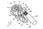
以上のように構成されたL型同軸コネクタ10は、以下に説明する手順により組立てられる。図6及び図7は、L型同軸コネクタ10の組立て途中における分解斜視図である。図8ないし図10は、L型同軸コネクタ10の組立て時における工程断面図である。   The L-shaped coaxial connector 10 configured as described above is assembled according to the procedure described below. 6 and 7 are exploded perspective views of the L-shaped coaxial connector 10 during assembly. 8 to 10 are process cross-sectional views when the L-shaped coaxial connector 10 is assembled.

まず、図6に示すように、ハウジング12に対してブッシング14を取り付ける。より詳細には、円筒部20内に円形部36が収まると共に、支持部31間に保持部38が収まるように、z軸方向の正方向側からブッシング14をハウジング12に対して押し込むようにして取り付ける。この際、凸部40が、図5に示すように、円筒部20の凹部に挿入される。   First, as shown in FIG. 6, a bushing 14 is attached to the housing 12. More specifically, the bushing 14 is pushed into the housing 12 from the positive side in the z-axis direction so that the circular portion 36 is accommodated in the cylindrical portion 20 and the holding portion 38 is accommodated between the support portions 31. Install. At this time, the convex portion 40 is inserted into the concave portion of the cylindrical portion 20 as shown in FIG.

次に、図6及び図7に示すように、ブッシング14に対してソケット16を取り付ける。より詳細には、円筒部41内に円筒部48が収まると共に、支持部44間に背面部50及び取り付け部52が収まるように、z軸方向の正方向側からソケット16をブッシング14に対して取り付ける(図6及び図7では、一方の支持部44のみ記載)。この状態では、かしめ部26が折り曲げられていないので、ブッシング14は、z軸方向の正方向に向かって露出している。   Next, as shown in FIGS. 6 and 7, the socket 16 is attached to the bushing 14. More specifically, the socket 16 is connected to the bushing 14 from the positive side in the z-axis direction so that the cylindrical portion 48 is accommodated in the cylindrical portion 41 and the back surface portion 50 and the attachment portion 52 are accommodated between the support portions 44. Attach (only one support portion 44 is shown in FIGS. 6 and 7). In this state, since the caulking portion 26 is not bent, the bushing 14 is exposed in the positive direction of the z-axis direction.

次に、図7に示すように、同軸ケーブル220をL型同軸コネクタ10に対して取り付ける。この際、同軸ケーブル220は、先端において、外導体222及び絶縁膜223が露出するように加工されている。ただし、中心導体224は、露出していない。絶縁膜223が取り付け部52上に位置し、外導体222がかしめ部28間に位置し、絶縁膜221がかしめ部30間に位置するように、同軸ケーブル220をL型同軸コネクタ10に載置する。   Next, as shown in FIG. 7, the coaxial cable 220 is attached to the L-shaped coaxial connector 10. At this time, the coaxial cable 220 is processed so that the outer conductor 222 and the insulating film 223 are exposed at the tip. However, the center conductor 224 is not exposed. The coaxial cable 220 is placed on the L-shaped coaxial connector 10 such that the insulating film 223 is located on the attachment portion 52, the outer conductor 222 is located between the caulking portions 28, and the insulating film 221 is located between the caulking portions 30. To do.

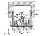
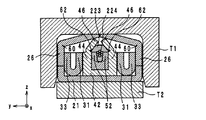
同軸ケーブル220を載置すると、かしめ部26,28,30のかしめ工程を行う。かしめ工程は、図8ないし図10に示すように、治具T1,T2を用いて行われる。まず、L型同軸コネクタ10を治具T2上に載置する。次に、図8に示すように、治具T1をz軸方向の正方向側から下降させる。治具T1は、図8に示すように、z軸方向の負方向側が開口したコ字型の断面構造を有している。そこで、治具T1内にL型同軸コネクタ10が収まるように、治具T1を下降させる。   When the coaxial cable 220 is placed, the caulking process of the caulking portions 26, 28, and 30 is performed. The caulking process is performed using jigs T1 and T2, as shown in FIGS. First, the L-shaped coaxial connector 10 is placed on the jig T2. Next, as shown in FIG. 8, the jig T1 is lowered from the positive direction side in the z-axis direction. As shown in FIG. 8, the jig T1 has a U-shaped cross-sectional structure with an opening on the negative side in the z-axis direction. Therefore, the jig T1 is lowered so that the L-shaped coaxial connector 10 is accommodated in the jig T1.

治具T1を下降させていくと、かしめ部26が治具T1に接触する。かしめ部26には、図8に示すように、溝60が設けられているので、治具T1よりz軸方向の正方向側から力を受けると、該溝60において折れ曲がる。   As the jig T1 is lowered, the caulking portion 26 comes into contact with the jig T1. As shown in FIG. 8, the caulking portion 26 is provided with a groove 60. Therefore, when a force is applied from the jig T1 from the positive side in the z-axis direction, the caulking portion 26 bends.

更に、治具T1を下降させていくと、図9に示すように、かしめ部26は、蓋部46に接触する。図8に示すように、支持部44と蓋部46との間には、溝62が設けられている。そのため、蓋部46は、かしめ部26よりz軸方向の正方向側から力を受けると、図9に示すように、溝62において折れ曲がる。   As the jig T1 is further lowered, the caulking portion 26 comes into contact with the lid portion 46 as shown in FIG. As shown in FIG. 8, a groove 62 is provided between the support portion 44 and the lid portion 46. Therefore, when receiving a force from the positive side in the z-axis direction from the caulking portion 26, the lid portion 46 bends in the groove 62 as shown in FIG.

蓋部46が折れ曲がると、同軸ケーブル220の絶縁膜223は、該蓋部46により取り付け部52に抑え付けられるようになる。このとき、絶縁膜223の一部は、取り付け部52により切断される。これにより、図9に示すように、同軸ケーブル220の中心導体224が、取り付け部52の隙間内に進入していく。   When the lid portion 46 is bent, the insulating film 223 of the coaxial cable 220 is suppressed to the attachment portion 52 by the lid portion 46. At this time, a part of the insulating film 223 is cut by the attachment portion 52. Thereby, as shown in FIG. 9, the center conductor 224 of the coaxial cable 220 enters the gap of the attachment portion 52.

更に、治具T1を下降させていくと、図10に示すように、かしめ部26が閉じると共に、蓋部46が閉じる。この際、かしめ部26は、ブッシング14及び固定部24を挟んで背面部21と対向するように折り曲げられることにより、該ブッシング14をハウジング12に固定している。更に、固定部24は、y軸方向において、ブッシング14とかしめ部26との間に位置し、弾性部33は、かしめ部26に圧接するようになる。   When the jig T1 is further lowered, the caulking portion 26 is closed and the lid portion 46 is closed as shown in FIG. At this time, the caulking portion 26 is bent so as to face the back surface portion 21 with the bushing 14 and the fixing portion 24 interposed therebetween, thereby fixing the bushing 14 to the housing 12. Further, the fixing portion 24 is located between the bushing 14 and the caulking portion 26 in the y-axis direction, and the elastic portion 33 comes into pressure contact with the caulking portion 26.

また、同軸ケーブル220の中心導体224は、取り付け部52の隙間の間に位置するようになる。これにより、ソケット16と中心導体224とが電気的に接続されるようになる。   Further, the central conductor 224 of the coaxial cable 220 is positioned between the gaps of the attachment portion 52. As a result, the socket 16 and the central conductor 224 are electrically connected.

なお、かしめ部26のかしめ工程において、かしめ部28,30も同時にかしめることが可能である。かしめ部28は、外導体222の周囲を取り囲むようにかしめられる。これにより、ハウジング12と外導体222とは、かしめ部28において電気的に接続されるようになる。また、かしめ部30は、絶縁膜221を取り囲むようにかしめられる。以上の工程を経て、L型同軸コネクタ10は、図1に示すような構成を有するようになる。   In the caulking process of the caulking portion 26, the caulking portions 28 and 30 can be caulked simultaneously. The caulking portion 28 is caulked so as to surround the outer conductor 222. As a result, the housing 12 and the outer conductor 222 are electrically connected at the caulking portion 28. Further, the caulking portion 30 is caulked so as to surround the insulating film 221. Through the above steps, the L-shaped coaxial connector 10 has a configuration as shown in FIG.

次に、L型同軸コネクタ10のレセプタクル230への着脱について説明する。レセプタクル230は、図17に示すように、外部導体232及び中心導体234により構成されている。外部導体232は、円筒形状の電極である。中心導体234は、外部導体232の中心に延在している電極である。   Next, attachment / detachment of the L-shaped coaxial connector 10 to the receptacle 230 will be described. As shown in FIG. 17, the receptacle 230 includes an outer conductor 232 and a center conductor 234. The outer conductor 232 is a cylindrical electrode. The center conductor 234 is an electrode that extends to the center of the outer conductor 232.

前記L型同軸コネクタ10をレセプタクル230に装着する際には、図3(a)及び図3(b)に示すように、外部導体232を開口O1から円筒部20に挿入する。これにより、円筒部20の内周面と外部導体232の外周面とが接触し、同軸ケーブル220の外導体222とレセプタクル230の外部導体232とがハウジング12を介して電気的に接続されるようになる。この際、円筒部20は、外部導体232により押し広げられる。これにより、円筒部20の内周面が、外部導体232の外周面に圧接するようになり、L型同軸コネクタ10がレセプタクル230から容易に外れることが防止されている。   When the L-shaped coaxial connector 10 is attached to the receptacle 230, the outer conductor 232 is inserted into the cylindrical portion 20 through the opening O1, as shown in FIGS. 3 (a) and 3 (b). As a result, the inner peripheral surface of the cylindrical portion 20 and the outer peripheral surface of the outer conductor 232 are in contact with each other so that the outer conductor 222 of the coaxial cable 220 and the outer conductor 232 of the receptacle 230 are electrically connected via the housing 12. become. At this time, the cylindrical portion 20 is expanded by the outer conductor 232. As a result, the inner peripheral surface of the cylindrical portion 20 comes into pressure contact with the outer peripheral surface of the outer conductor 232, and the L-shaped coaxial connector 10 is prevented from being easily detached from the receptacle 230.

また、外部導体232が円筒部20に挿入されると同時に、図3(a)及び図3(b)に示すように、中心導体234がソケット16の円筒部48に挿入される。これにより、中心導体234の外周面と円筒部48の内周面とが接触し、同軸ケーブル220の中心導体224とレセプタクル230の中心導体234とがソケット16を介して電気的に接続されるようになる。   Further, at the same time as the outer conductor 232 is inserted into the cylindrical portion 20, the center conductor 234 is inserted into the cylindrical portion 48 of the socket 16 as shown in FIGS. 3 (a) and 3 (b). As a result, the outer peripheral surface of the central conductor 234 and the inner peripheral surface of the cylindrical portion 48 are in contact with each other, so that the central conductor 224 of the coaxial cable 220 and the central conductor 234 of the receptacle 230 are electrically connected via the socket 16. become.

(効果)
以上のように構成されたL型同軸コネクタ10は、以下に説明するように、安価に作製可能である。より詳細には、L型同軸コネクタ10では、図5に示すように、背面部39の半径R1は、円筒部20の半径R2以下の大きさを有している。そのため、背面部39は、z軸方向の正方向側から円筒部20の開口O1を通過することができる。すなわち、背面部39をz軸方向の正方向側から取り付けることが可能である。更に、かしめ部26は、ブッシング14を挟んで背面部21と対向するように折り曲げられてブッシング14とハウジング12とを固定している。そのため、かしめ部26が折り曲げられる前の状態では、ブッシング14の保持部38は、図2に示すように、z軸方向の正方向側に向かって露出している。故に、ブッシング14の保持部38をz軸方向の正方向側からハウジング12に取り付けることが可能である。故に、L型同軸コネクタ10では、ブッシング14をz軸方向の正方向側からハウジング12に対して取り付けることができる。
(effect)
The L-shaped coaxial connector 10 configured as described above can be manufactured at a low cost as described below. More specifically, in the L-shaped coaxial connector 10, as shown in FIG. 5, the radius R <b> 1 of the back surface portion 39 is smaller than the radius R <b> 2 of the cylindrical portion 20. Therefore, the back surface portion 39 can pass through the opening O1 of the cylindrical portion 20 from the positive side in the z-axis direction. That is, the back surface portion 39 can be attached from the positive direction side in the z-axis direction. Further, the caulking portion 26 is bent so as to face the back surface portion 21 with the bushing 14 interposed therebetween, and fixes the bushing 14 and the housing 12. Therefore, in a state before the caulking portion 26 is bent, the holding portion 38 of the bushing 14 is exposed toward the positive side in the z-axis direction, as shown in FIG. Therefore, the holding portion 38 of the bushing 14 can be attached to the housing 12 from the positive direction side in the z-axis direction. Therefore, in the L-shaped coaxial connector 10, the bushing 14 can be attached to the housing 12 from the positive side in the z-axis direction.

前記のようにブッシング14をz軸方向の正方向側からハウジング12に対して取り付けることができる場合には、図2に示すように円筒部20の開口O2が背面部21により覆われた状態であっても、ブッシング14をハウジング12に対して取り付けることが可能となる。したがって、L型同軸コネクタ10では、図4に示すハウジング12を作製する工程と、背面部21を折り曲げる工程と1つのライン上において連続して行うことができる。その結果、L型同軸コネクタ10を安価に作製することが可能となる。   When the bushing 14 can be attached to the housing 12 from the positive side in the z-axis direction as described above, the opening O2 of the cylindrical portion 20 is covered with the back surface portion 21 as shown in FIG. Even if it exists, it becomes possible to attach the bushing 14 with respect to the housing 12. Therefore, in the L-shaped coaxial connector 10, the process of manufacturing the housing 12 shown in FIG. 4 and the process of bending the back surface portion 21 can be performed continuously on one line. As a result, the L-shaped coaxial connector 10 can be manufactured at a low cost.

また、L型同軸コネクタ10によれば、以下に説明するように、ハウジング12を精度良く組み立てることができる。より詳細には、従来の同軸コネクタ210の製造では、図17の状態のハウジング212を作製する工程と、ハウジング212の蓋部228を閉じる工程とは異なる者により行われる。より詳細には、ハウジング212の作製は、プレス加工を専門とする者により行われるのに対して、蓋部228を閉じる工程は、プレス加工を専門としない者(同軸コネクタ210の生産者)により行われる。プレス加工を専門とする者は、プレス加工を専門としない者よりも、蓋部228を閉じるような金属加工を精度良く行うことができる。したがって、同軸コネクタ210の作製において、ハウジング212の蓋部228を閉じる工程は、プレス加工を専門とする者により行われることが望ましい。   Further, according to the L-shaped coaxial connector 10, the housing 12 can be assembled with high accuracy as described below. More specifically, in the manufacture of the conventional coaxial connector 210, the process of manufacturing the housing 212 in the state of FIG. 17 and the process of closing the lid portion 228 of the housing 212 are performed by different persons. More specifically, the housing 212 is manufactured by a person who specializes in pressing, whereas the process of closing the lid 228 is performed by a person who does not specialize in pressing (the producer of the coaxial connector 210). Done. A person who specializes in pressing can perform metal processing such as closing the lid 228 with higher accuracy than a person who does not specialize in pressing. Therefore, in the production of the coaxial connector 210, the step of closing the cover 228 of the housing 212 is preferably performed by a person who specializes in press working.

しかしながら、プレス加工を専門とする者が蓋部228を閉じる工程を行うことは、製造コストの観点から好ましくない。より詳細には、蓋部228を閉じる工程は、ブッシング214等の取り付け工程後に行われる。そのため、同軸コネクタ210において、プレス加工を専門とする者が蓋部228を閉じるためには、プレス加工を専門としない者がブッシング214等を取り付けた後に、プレス加工を専門とする者に同軸コネクタ210の半製品を引き渡す必要がある。故に、プレス加工を専門とする者とプレス加工を専門としない者との間を同軸コネクタ210の半製品が行き来することになり、製造コストが大幅に増加してしまう。   However, it is not preferable from the viewpoint of manufacturing cost that a person who specializes in press working performs the process of closing the lid 228. More specifically, the process of closing the lid 228 is performed after the process of attaching the bushing 214 and the like. Therefore, in the coaxial connector 210, in order for a person who specializes in press working to close the lid 228, a person who does not specialize in press work attaches the bushing 214 and the like to a person who specializes in press work and then coaxial connector. It is necessary to deliver 210 semi-finished products. Therefore, the semi-finished product of the coaxial connector 210 goes back and forth between a person who specializes in press work and a person who does not specialize in press work, and the manufacturing cost is greatly increased.

一方、L型同軸コネクタ10では、背面部21が折り曲げられた状態のハウジング12に対して、ブッシング14及びソケット16を取り付けることが可能である。故に、L型同軸コネクタ10の生産者は、図2に示すように、背面部21が折り曲げられた状態のハウジング12を購入し、該ハウジング12に対してブッシング14及びソケット16を取り付けることにより、L型同軸コネクタ10を作製できる。そのため、ハウジング12の背面部21を折り曲げる工程は、プレス加工を専門とする者により行われるようになる。その結果、L型同軸コネクタ10では、ハウジング12が精度良く組立てられるようになる。   On the other hand, in the L-shaped coaxial connector 10, the bushing 14 and the socket 16 can be attached to the housing 12 in a state where the back surface portion 21 is bent. Therefore, as shown in FIG. 2, the producer of the L-shaped coaxial connector 10 purchases the housing 12 in which the back surface portion 21 is bent, and attaches the bushing 14 and the socket 16 to the housing 12. The L-shaped coaxial connector 10 can be produced. Therefore, the process of bending the back surface portion 21 of the housing 12 is performed by a person who specializes in pressing. As a result, in the L-shaped coaxial connector 10, the housing 12 can be assembled with high accuracy.

また、L型同軸コネクタ10では、図4に示すように、凹部32及び凸部34が設けられている。そのため、凹部32と凸部34とが係合することにより、固定部24に対してかしめ部26が固定されるようになる。その結果、かしめ部26がかしめられていない状態であっても、ハウジング12は、図2に示すように、背面部21が折り曲げられて開口O2を覆った状態を維持することができる。   Further, the L-shaped coaxial connector 10 is provided with a concave portion 32 and a convex portion 34 as shown in FIG. For this reason, the caulking portion 26 is fixed to the fixing portion 24 by the engagement of the concave portion 32 and the convex portion 34. As a result, even if the caulking portion 26 is not caulked, the housing 12 can maintain the state where the back surface portion 21 is bent and covers the opening O2, as shown in FIG.

(変形例)
L型同軸コネクタ10は、前記実施形態に示したものに限らない。よって、L型同軸コネクタ10は、その要旨の範囲内において、変更可能である。以下に、L型同軸コネクタ10の変形例について図面を参照しながら説明する。図11及び図12は、その他の組立て方によるL型同軸コネクタ10の組立て途中における分解斜視図である。
(Modification)
The L-shaped coaxial connector 10 is not limited to that shown in the embodiment. Therefore, the L-shaped coaxial connector 10 can be changed within the scope of the gist. Below, the modification of the L-shaped coaxial connector 10 is demonstrated, referring drawings. 11 and 12 are exploded perspective views in the middle of assembling the L-shaped coaxial connector 10 by other assembling methods.

前記実施形態では、図6及び図7に示すように、ブッシング14をハウジング12に対して取り付けた後に、ソケット16をブッシング14に取り付けている。しかしながら、ブッシング14及びソケット16の取り付け順はこれに限らない。例えば、図11に示すように、ソケット16をブッシング14に取り付けた後に、図12に示すように、ブッシング14をハウジング12に取り付けるようにしてもよい。   In the embodiment, as shown in FIGS. 6 and 7, the socket 16 is attached to the bushing 14 after the bushing 14 is attached to the housing 12. However, the order of attaching the bushing 14 and the socket 16 is not limited to this. For example, as shown in FIG. 11, after the socket 16 is attached to the bushing 14, the bushing 14 may be attached to the housing 12 as shown in FIG. 12.

また、ブッシング14では、図2に示すように、円筒部41に切り欠きが設けられている。このような切り欠きが設けられることにより、ソケット16をブッシング14に対してz軸方向の正方向側から取り付けることができるようになる。   Moreover, in the bushing 14, as shown in FIG. 2, the cylindrical part 41 is provided with a notch. By providing such a notch, the socket 16 can be attached to the bushing 14 from the positive side in the z-axis direction.

しかしながら、ブッシング14では、図3(b)のAの位置において、ソケット16と外部導体232とが短絡するおそれがある。より詳細には、円筒部41に切り欠きが設けられていると、該切り欠きの部分において、ソケット16の背面部50は、z軸方向の正方向に向かって露出するようになる。このようなソケット16を有するL型同軸コネクタ10に対して、レセプタクル230が取り付けられると、背面部50が露出している部分において、背面部50と外部導体232とが近接してしまう。その結果、L型同軸コネクタ10がレセプタクル230に強く押し付けられてしまった場合等に、ソケット16と外部導体232とが短絡してしまうおそれがある。   However, in the bushing 14, the socket 16 and the external conductor 232 may be short-circuited at the position A in FIG. More specifically, when the cylindrical portion 41 is provided with a notch, the back portion 50 of the socket 16 is exposed in the positive direction in the z-axis direction at the notched portion. When the receptacle 230 is attached to the L-shaped coaxial connector 10 having such a socket 16, the back portion 50 and the external conductor 232 are close to each other in the portion where the back portion 50 is exposed. As a result, when the L-shaped coaxial connector 10 is strongly pressed against the receptacle 230, the socket 16 and the external conductor 232 may be short-circuited.

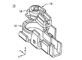
そこで、図13の外観斜視図に示すブッシング14'を用いてもよい。図13に示すブッシング14'は、円筒部41に切り欠きが設けられていない。その代わり、ブッシング14'が、xz平面により2つに分割されている。更に、円筒部41の下面と背面部42の上面との間に隙間SP2が設けられている。隙間SP2を通過するように背面部42上にソケット16を載置する。そして、2つに分割されているブッシング14'を接合する。この後、ブッシング14'及び同軸ケーブル220を、図11及び図12に示した工程と同様の工程によりハウジング12に取り付ける。最後に、かしめ部26,28,30をかしめることにより、L型同軸コネクタ10が完成する。   Therefore, a bushing 14 ′ shown in the external perspective view of FIG. 13 may be used. In the bushing 14 ′ shown in FIG. 13, the cylindrical portion 41 is not provided with a notch. Instead, the bushing 14 'is divided into two by the xz plane. Further, a gap SP <b> 2 is provided between the lower surface of the cylindrical portion 41 and the upper surface of the back surface portion 42. The socket 16 is placed on the back surface portion 42 so as to pass through the gap SP2. Then, the bushing 14 'divided into two is joined. Thereafter, the bushing 14 ′ and the coaxial cable 220 are attached to the housing 12 by a process similar to the process shown in FIGS. 11 and 12. Finally, the L-shaped coaxial connector 10 is completed by caulking the caulking portions 26, 28, and 30.

図13に示すブッシング14'を用いた場合には、円筒部41に切り欠きが設けられていないので、ソケット16の背面部50がz軸方向の正方向側に向かって露出することがない。よって、L型同軸コネクタ10がレセプタクル230に強く押し付けられてしまった場合等においても、ソケット16と外部導体232とが短絡してしまうおそれがない。ただし、ブッシング14'を用いた場合には、ブッシング14'に対してソケット16を取り付けた後に、ブッシング14'をハウジング12に取り付ける必要がある。   When the bushing 14 ′ shown in FIG. 13 is used, since the notch is not provided in the cylindrical portion 41, the back surface portion 50 of the socket 16 is not exposed toward the positive direction side in the z-axis direction. Therefore, even when the L-shaped coaxial connector 10 is strongly pressed against the receptacle 230, the socket 16 and the external conductor 232 are not short-circuited. However, when the bushing 14 ′ is used, it is necessary to attach the bushing 14 ′ to the housing 12 after attaching the socket 16 to the bushing 14 ′.

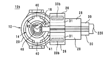
また、前記実施形態に係るL型同軸コネクタ10では、弾性部33は、図2に示すように、支持部31をU字型に折り曲げて作製されているが、弾性部33の構造は、これに限らない。図14は、第1の変形例に係るL型同軸コネクタ10aを平面視した図である。図15は、第2の変形例に係るL型同軸コネクタ10bを平面視した図である。   In the L-shaped coaxial connector 10 according to the embodiment, the elastic portion 33 is produced by bending the support portion 31 into a U shape as shown in FIG. 2, but the structure of the elastic portion 33 is as follows. Not limited to. FIG. 14 is a plan view of the L-shaped coaxial connector 10a according to the first modification. FIG. 15 is a plan view of the L-shaped coaxial connector 10b according to the second modification.

L型同軸コネクタ10aでは、かしめ部26及び支持部31は、隙間SP3を空けて設けられた板状部材である。かしめ部26は、弾性部33aを備えている。より詳細には、弾性部33aは、かしめ部26の一部が折り曲げられて、支持部31に圧接している。該L型同軸コネクタ10aにおいても、L型同軸コネクタ10と同様に、かしめ部26と支持部31との間に弾性力を働かせることができるので、円筒部20が外部導体232に圧接する力を適切な大きさに設定することが容易となる。その結果、L型同軸コネクタ10aを適度な力でレセプタクルに着脱することができるようになる。なお、図14に示したL型同軸コネクタ10aでは、弾性部33aは、かしめ部26の一部が折り曲げられて作製されていると共に、支持部31に対して圧接しているが、弾性部33aは、例えば、支持部31の一部が折り曲げられて作成されていると共に、かしめ部26に対して圧接していてもよい。   In the L-shaped coaxial connector 10a, the caulking portion 26 and the support portion 31 are plate-like members provided with a gap SP3. The caulking portion 26 includes an elastic portion 33a. More specifically, the elastic portion 33 a is in pressure contact with the support portion 31 by bending a part of the caulking portion 26. Also in the L-type coaxial connector 10 a, as in the L-type coaxial connector 10, an elastic force can be applied between the caulking portion 26 and the support portion 31, so that the force with which the cylindrical portion 20 is pressed against the external conductor 232 It becomes easy to set to an appropriate size. As a result, the L-shaped coaxial connector 10a can be attached to and detached from the receptacle with an appropriate force. In the L-shaped coaxial connector 10a shown in FIG. 14, the elastic portion 33a is formed by bending a part of the caulking portion 26 and is in pressure contact with the support portion 31, but the elastic portion 33a. For example, a part of the support portion 31 may be bent and may be pressed against the caulking portion 26.

また、弾性部33は、図15に示す弾性部33bのように、ハウジング12とは別体であってもよい。該弾性部33bは、かしめ部26と支持部31との間に設けられているエラストマーからなる弾性体である。該L型同軸コネクタ10bにおいても、L型同軸コネクタ10と同様に、かしめ部26と支持部31との間に弾性力を働かせることができるので、円筒部20が外部導体232に圧接する力を適切な大きさに設定することが容易となる。その結果、L型同軸コネクタ10bを適度な力でレセプタクルに着脱することができるようになる。   Moreover, the elastic part 33 may be a separate body from the housing 12 like the elastic part 33b shown in FIG. The elastic portion 33 b is an elastic body made of an elastomer provided between the caulking portion 26 and the support portion 31. Also in the L-shaped coaxial connector 10b, as in the L-shaped coaxial connector 10, an elastic force can be exerted between the caulking portion 26 and the support portion 31, so that the force that the cylindrical portion 20 presses against the outer conductor 232 is exerted. It becomes easy to set to an appropriate size. As a result, the L-shaped coaxial connector 10b can be attached to and detached from the receptacle with an appropriate force.

また、前記実施形態に係るL型同軸コネクタ10では、図5に示すように、背面部39から突出している凸部40と円筒部20の内周面に設けられている凹部とが係合することにより、ブッシング14がハウジング12から抜け落ちることを防止している。ただし、ブッシング14がハウジング12から抜け落ちることを防止する構成はこれに限らない。図16は、第3の変形例に係るL型同軸コネクタ10cを平面視した図である。   Moreover, in the L-shaped coaxial connector 10 according to the embodiment, as shown in FIG. 5, the convex portion 40 protruding from the back surface portion 39 engages with the concave portion provided on the inner peripheral surface of the cylindrical portion 20. As a result, the bushing 14 is prevented from falling off the housing 12. However, the configuration for preventing the bushing 14 from falling off the housing 12 is not limited thereto. FIG. 16 is a plan view of an L-shaped coaxial connector 10c according to a third modification.

図16に示すように、ハウジング12は、開口O1において、円筒部20の内側に向かって突出している凸部60を更に備えていてもよい。これにより、凸部60は、z軸方向から平面視したときに、ブッシング14と僅かに重なることにより、ブッシング14がハウジング12から抜け落ちることを防止している。   As illustrated in FIG. 16, the housing 12 may further include a convex portion 60 that protrudes toward the inside of the cylindrical portion 20 in the opening O1. Thereby, the convex part 60 prevents the bushing 14 from falling out of the housing 12 by slightly overlapping the bushing 14 when viewed in plan from the z-axis direction.

本発明の一実施形態に係るL型同軸コネクタの外観斜視図である。1 is an external perspective view of an L-shaped coaxial connector according to an embodiment of the present invention. 図1のL型同軸コネクタの分解斜視図である。It is a disassembled perspective view of the L-shaped coaxial connector of FIG. 図1のL型同軸コネクタの断面構造図である。FIG. 2 is a cross-sectional structure diagram of the L-shaped coaxial connector of FIG. 1. 図1のL型同軸コネクタのハウジングの組立て途中における斜視図である。It is a perspective view in the middle of the assembly of the housing of the L-shaped coaxial connector of FIG. 図1のL型同軸コネクタを平面視した図である。It is the figure which planarly viewed the L-shaped coaxial connector of FIG. 図1のL型同軸コネクタの組立て途中における分解斜視図である。It is a disassembled perspective view in the middle of the assembly of the L-shaped coaxial connector of FIG. 図1のL型同軸コネクタの組立て途中における分解斜視図である。It is a disassembled perspective view in the middle of the assembly of the L-shaped coaxial connector of FIG. 図1のL型同軸コネクタの組立て時における工程断面図である。It is process sectional drawing at the time of the assembly of the L-shaped coaxial connector of FIG. 図1のL型同軸コネクタの組立て時における工程断面図である。It is process sectional drawing at the time of the assembly of the L-shaped coaxial connector of FIG. 図1のL型同軸コネクタの組立て時における工程断面図である。It is process sectional drawing at the time of the assembly of the L-shaped coaxial connector of FIG. その他の組立て方によるL型同軸コネクタの組立て途中における分解斜視図である。It is a disassembled perspective view in the middle of the assembly of the L-shaped coaxial connector by the other assembly method. その他の組立て方によるL型同軸コネクタの組立て途中における分解斜視図である。It is a disassembled perspective view in the middle of the assembly of the L-shaped coaxial connector by the other assembly method. 変形例に係るブッシングの外観斜視図である。It is an external appearance perspective view of the bushing which concerns on a modification. 第1の変形例に係るL型同軸コネクタを平面視した図である。It is the figure which planarly viewed the L-shaped coaxial connector which concerns on a 1st modification. 第2の変形例に係るL型同軸コネクタを平面視した図である。It is the figure which planarly viewed the L-shaped coaxial connector which concerns on a 2nd modification. 第3の変形例に係るL型同軸コネクタを平面視した図である。It is the figure which planarly viewed the L-shaped coaxial connector which concerns on a 3rd modification. 特許文献1に記載の同軸コネクタ及びレセプタクルの分解斜視図である。It is a disassembled perspective view of the coaxial connector and receptacle of patent document 1. FIG.

符号の説明Explanation of symbols

O1,O2 開口
10,10a,10b,10c L型同軸コネクタ
12 ハウジング
14,14' ブッシング
16 ソケット
20,41,48 円筒部
21,39,42,50 背面部
22,46 蓋部
23 延在部
24 固定部
26,28,30 かしめ部
31,44 支持部
32 凹部
33,33a,33b 弾性部
34,40,60 凸部
36 円形部
38 保持部
52 取り付け部
O1, O2 opening 10, 10a, 10b, 10c L-shaped coaxial connector 12 Housing 14, 14 'bushing 16 Socket 20, 41, 48 Cylindrical part 21, 39, 42, 50 Back part 22, 46 Lid part 23 Extension part 24 Fixing part 26, 28, 30 Caulking part 31, 44 Support part 32 Concave part 33, 33a, 33b Elastic part 34, 40, 60 Convex part 36 Circular part 38 Holding part 52 Attachment part

Claims (7)

中心導体及び外部導体を有するレセプタクルに着脱可能なL型同軸コネクタにおいて、
第1の開口及び第2の開口を有していると共に、該第1の開口から挿入される前記外部導体と接触する円筒部、及び、該円筒部に接続されていると共に、該第2の開口を覆っている背面部を有しており、1枚の金属板により作製されているハウジングと、
前記ハウジングに取り付けられているブッシングと、
前記ブッシングに取り付けられ、かつ、該ブッシングにより前記ハウジングと絶縁されているソケットであって、前記中心導体と接続されるソケットと、
を備え、
前記ブッシングにおいて前記円筒部に収まっている部分の径は、前記第1の開口の径以下の大きさを有しており、
前記ハウジングは、
前記背面部から延在しているかしめ部であって、前記ブッシングを挟んで該背面部と対向するように折り曲げられることにより、該ブッシングを前記ハウジングに固定しているかしめ部を、
更に含んでいること、
を特徴とするL型同軸コネクタ。
In an L-shaped coaxial connector that can be attached to and detached from a receptacle having a center conductor and an outer conductor,
A cylindrical portion having a first opening and a second opening, in contact with the outer conductor inserted from the first opening, and connected to the cylindrical portion, and the second opening A housing having a back surface covering the opening and made of a single metal plate;
A bushing attached to the housing;
A socket attached to the bushing and insulated from the housing by the bushing, the socket being connected to the central conductor;
With
The diameter of the portion of the bushing that is accommodated in the cylindrical portion has a size equal to or smaller than the diameter of the first opening,
The housing is
A caulking portion extending from the back surface portion, the caulking portion fixing the bushing to the housing by being bent so as to face the back surface portion with the bushing interposed therebetween,
Including further,
An L-shaped coaxial connector.
前記ハウジングは、
前記かしめ部が折り曲げられていない状態においても、前記背面部が前記第2の開口を覆った状態を維持可能とする保持機構を、
更に備えていること、
を特徴とする請求項1に記載のL型同軸コネクタ。
The housing is
A holding mechanism capable of maintaining a state in which the back portion covers the second opening even in a state where the caulking portion is not bent;
More
The L-shaped coaxial connector according to claim 1.
前記ハウジングは、
前記円筒部に接続され、前記背面部上において前記ブッシングと並んでいる固定部を、
更に備え、
前記かしめ部は、前記ブッシング及び前記固定部を挟んで前記背面部と対向するように折り曲げられており、
前記保持機構は、前記かしめ部又は前記固定部のいずれか一方に設けられている第1の凸部と、該かしめ部又は該固定部のいずれか他方に設けられ、該第1の凸部と係合する第2の凹部とにより構成されていること、
を特徴とする請求項2に記載のL型同軸コネクタ。
The housing is
A fixed part connected to the cylindrical part and aligned with the bushing on the back part,
In addition,
The caulking part is bent so as to face the back part across the bushing and the fixing part,
The holding mechanism is provided with a first convex portion provided in either the caulking portion or the fixing portion, and provided in either the caulking portion or the fixing portion, and the first convex portion The second concave portion to be engaged;
The L-shaped coaxial connector according to claim 2.
前記第2の開口から前記第1の開口へと向かう方向を第1の方向とした場合において、前記かしめ部が折り曲げられていない状態では、前記ブッシングは、前記ハウジングから前記第1の方向に向かって露出していること、
を特徴とする請求項1ないし請求項3のいずれかに記載のL型同軸コネクタ。
When the direction from the second opening toward the first opening is the first direction, the bushing is directed from the housing toward the first direction when the caulking portion is not bent. Being exposed,
The L-shaped coaxial connector according to any one of claims 1 to 3, wherein:
前記ハウジングは、同軸ケーブルの外導体に電気的に接続され、
前記ソケットは、前記同軸ケーブルの中心導体に電気的に接続されていること、
を特徴とする請求項1ないし請求項4のいずれかに記載のL型同軸コネクタ。
The housing is electrically connected to an outer conductor of a coaxial cable;
The socket is electrically connected to a central conductor of the coaxial cable;
The L-shaped coaxial connector according to claim 1, wherein:
前記ブッシングは、
前記円筒部に収まっている部分の中心から延在している第2の凸部を、
更に備え、
前記第2の凸部は、前記円筒部の内周面に設けられた凹部に挿入されていること、
を特徴とする請求項1ないし請求項5のいずれかに記載のL型同軸コネクタ。
The bushing is
A second convex portion extending from the center of the portion accommodated in the cylindrical portion,
In addition,
The second convex portion is inserted into a concave portion provided on the inner peripheral surface of the cylindrical portion;
The L-shaped coaxial connector according to claim 1, wherein:
前記ハウジングは、
前記第1の開口において、前記円筒部の内側に向かって突出している第3の凸部を、
更に備えていること、
を特徴とする請求項1ないし請求項5のいずれかに記載のL型同軸コネクタ。
The housing is
In the first opening, a third convex portion protruding toward the inside of the cylindrical portion,
More
The L-shaped coaxial connector according to claim 1, wherein:
JP2008231758A 2008-09-10 2008-09-10 L-type coaxial connector Active JP4720881B2 (en)

Priority Applications (6)

Application Number Priority Date Filing Date Title
JP2008231758A JP4720881B2 (en) 2008-09-10 2008-09-10 L-type coaxial connector
TW098126893A TWI382607B (en) 2008-09-10 2009-08-11 L-shaped coaxial connector
US12/544,417 US8047871B2 (en) 2008-09-10 2009-08-20 L-shaped coaxial connector
KR1020090084934A KR101041318B1 (en) 2008-09-10 2009-09-09 L-shaped coaxial connector
CN2009101734139A CN101673909B (en) 2008-09-10 2009-09-10 L-shaped coaxial connector
EP09252155.8A EP2175524B1 (en) 2008-09-10 2009-09-10 L-shaped coaxial connector

Applications Claiming Priority (1)

Application Number Priority Date Filing Date Title
JP2008231758A JP4720881B2 (en) 2008-09-10 2008-09-10 L-type coaxial connector

Publications (2)

Publication Number Publication Date
JP2010067426A true JP2010067426A (en) 2010-03-25
JP4720881B2 JP4720881B2 (en) 2011-07-13

Family

ID=41664667

Family Applications (1)

Application Number Title Priority Date Filing Date
JP2008231758A Active JP4720881B2 (en) 2008-09-10 2008-09-10 L-type coaxial connector

Country Status (6)

Country Link
US (1) US8047871B2 (en)
EP (1) EP2175524B1 (en)
JP (1) JP4720881B2 (en)
KR (1) KR101041318B1 (en)
CN (1) CN101673909B (en)
TW (1) TWI382607B (en)

Cited By (3)

* Cited by examiner, † Cited by third party
Publication number Priority date Publication date Assignee Title
JP2011198528A (en) * 2010-03-18 2011-10-06 Jst Mfg Co Ltd Coaxial connector and board connector
JP2016110709A (en) * 2014-12-02 2016-06-20 ヒロセ電機株式会社 Coaxial cable connector with core wire holding and fixing function
JP2021125441A (en) * 2020-02-10 2021-08-30 ヒロセ電機株式会社 Coaxial electric connector

Families Citing this family (15)

* Cited by examiner, † Cited by third party
Publication number Priority date Publication date Assignee Title
US8317540B2 (en) * 2010-10-13 2012-11-27 Shih-Chieh Chen Coaxial connector with shielding shell
JP5408239B2 (en) * 2011-12-09 2014-02-05 株式会社村田製作所 installation method
JP2013157113A (en) * 2012-01-27 2013-08-15 Hosiden Corp Coaxial connector
JP5763007B2 (en) * 2012-04-19 2015-08-12 ヒロセ電機株式会社 Electrical connector
CN102842838B (en) * 2012-08-01 2015-01-07 番禺得意精密电子工业有限公司 Cable connector and manufacturing method thereof
JP5768989B2 (en) * 2013-09-06 2015-08-26 第一精工株式会社 Coaxial connector device
EP3092685A4 (en) 2014-01-07 2017-12-06 MiniPumps, LLC Welding washers for microwire welding
CN104183985A (en) * 2014-09-05 2014-12-03 江苏东升电子科技有限公司 Connector with metal rack
JP6593631B2 (en) * 2015-09-24 2019-10-23 株式会社オートネットワーク技術研究所 connector
JP6390862B2 (en) * 2016-03-23 2018-09-19 Smk株式会社 L-type coaxial connector
KR101788041B1 (en) * 2016-05-04 2017-10-19 주식회사 기가레인 Coaxial cable connector
WO2020031760A1 (en) * 2018-08-10 2020-02-13 株式会社村田製作所 Surface-mount connector and surface-mount connector set
CN113196591B (en) * 2018-12-19 2023-07-21 株式会社村田制作所 Positioning structure of insulating member in L-shaped coaxial connector
DE102019117473A1 (en) * 2019-06-28 2020-12-31 Tesat-Spacecom Gmbh & Co. Kg Circuit arrangement consisting of two interconnected high-frequency components
JP7344150B2 (en) * 2020-02-10 2023-09-13 ヒロセ電機株式会社 How to make coaxial electrical connectors

Citations (5)

* Cited by examiner, † Cited by third party
Publication number Priority date Publication date Assignee Title
JP2003331997A (en) * 2002-05-08 2003-11-21 Honda Tsushin Kogyo Co Ltd Mini-coaxial connector
JP2006179409A (en) * 2004-12-24 2006-07-06 I-Pex Co Ltd Receptacle connector for l-shaped coaxial cable
JP2006228614A (en) * 2005-02-18 2006-08-31 Murata Mfg Co Ltd Coaxial connector and communication apparatus
JP2008192369A (en) * 2007-02-01 2008-08-21 Japan Aviation Electronics Industry Ltd Connector
JP2010020948A (en) * 2008-07-09 2010-01-28 tian-mei Chen Connector of coaxial cable

Family Cites Families (8)

* Cited by examiner, † Cited by third party
Publication number Priority date Publication date Assignee Title
JP2504704B2 (en) * 1991-03-12 1996-06-05 ヒロセ電機株式会社 Coaxial cable connector and connection method
JP3120692B2 (en) * 1995-04-18 2000-12-25 株式会社村田製作所 Coaxial connector
JP3679651B2 (en) * 1999-07-30 2005-08-03 ヒロセ電機株式会社 L-type coaxial connector
US6416357B1 (en) * 2001-03-12 2002-07-09 Hon Hai Precision Ind. Co., Ltd. Cable end connector with low profile after assembly
US6712645B1 (en) * 2003-04-22 2004-03-30 Input Output Precise Corporation Cable fixture of coaxial connector
JP4136924B2 (en) * 2003-12-19 2008-08-20 ヒロセ電機株式会社 Coaxial electrical connector
JP4549277B2 (en) 2005-10-27 2010-09-22 矢崎総業株式会社 connector
CN201054430Y (en) 2007-01-31 2008-04-30 黄淑薰 Improved cable connector structure

Patent Citations (5)

* Cited by examiner, † Cited by third party
Publication number Priority date Publication date Assignee Title
JP2003331997A (en) * 2002-05-08 2003-11-21 Honda Tsushin Kogyo Co Ltd Mini-coaxial connector
JP2006179409A (en) * 2004-12-24 2006-07-06 I-Pex Co Ltd Receptacle connector for l-shaped coaxial cable
JP2006228614A (en) * 2005-02-18 2006-08-31 Murata Mfg Co Ltd Coaxial connector and communication apparatus
JP2008192369A (en) * 2007-02-01 2008-08-21 Japan Aviation Electronics Industry Ltd Connector
JP2010020948A (en) * 2008-07-09 2010-01-28 tian-mei Chen Connector of coaxial cable

Cited By (4)

* Cited by examiner, † Cited by third party
Publication number Priority date Publication date Assignee Title
JP2011198528A (en) * 2010-03-18 2011-10-06 Jst Mfg Co Ltd Coaxial connector and board connector
JP2016110709A (en) * 2014-12-02 2016-06-20 ヒロセ電機株式会社 Coaxial cable connector with core wire holding and fixing function
JP2021125441A (en) * 2020-02-10 2021-08-30 ヒロセ電機株式会社 Coaxial electric connector
JP7407611B2 (en) 2020-02-10 2024-01-04 ヒロセ電機株式会社 coaxial electrical connector

Also Published As

Publication number Publication date
KR101041318B1 (en) 2011-06-14
TW201014069A (en) 2010-04-01
US8047871B2 (en) 2011-11-01
KR20100030600A (en) 2010-03-18
CN101673909A (en) 2010-03-17
EP2175524B1 (en) 2016-06-01
US20100062639A1 (en) 2010-03-11
TWI382607B (en) 2013-01-11
EP2175524A1 (en) 2010-04-14
CN101673909B (en) 2012-05-30
JP4720881B2 (en) 2011-07-13

Similar Documents

Publication Publication Date Title
JP4720881B2 (en) L-type coaxial connector
JP4730415B2 (en) L-type coaxial connector
JP2010080262A (en) L-shaped coaxial connector and method for manufacturing the same
JP6840559B2 (en) connector
US8616924B2 (en) Female terminal for connector
WO2015025571A1 (en) Coaxial connector and connecting part
KR20160066513A (en) Coaxial cable connector having holding and fixing functions of core
JP2021018905A (en) connector
JP7232144B2 (en) connector
JP5053759B2 (en) Socket terminal
JP2009004147A (en) Coaxial connector with built-in capacitor
JP2008103153A (en) Socket terminal
TWI458209B (en) Installation of electrical connectors
KR102374774B1 (en) Coaxial cable connector having window and coaxial connector apparatus using the coaxial cable connector
US20180358740A1 (en) Shield connector and connector connection structure
JP2013097914A (en) Coaxial connector
JP2021044094A (en) Connector and connection method
JP5754593B2 (en) Coaxial connector device
JP2020072065A (en) Power supply connector device with improved terminal
JP4025588B2 (en) Wire clamp
JP2004356012A (en) Insulation displacement connector
TWM486193U (en) Improved structure of coaxial connector
JP2005093272A (en) Connection structure of flat harness and connector

Legal Events

Date Code Title Description
A621 Written request for application examination

Free format text: JAPANESE INTERMEDIATE CODE: A621

Effective date: 20100201

A977 Report on retrieval

Free format text: JAPANESE INTERMEDIATE CODE: A971007

Effective date: 20100628

A131 Notification of reasons for refusal

Free format text: JAPANESE INTERMEDIATE CODE: A131

Effective date: 20100720

A521 Written amendment

Free format text: JAPANESE INTERMEDIATE CODE: A523

Effective date: 20100906

TRDD Decision of grant or rejection written
A01 Written decision to grant a patent or to grant a registration (utility model)

Free format text: JAPANESE INTERMEDIATE CODE: A01

Effective date: 20110308

A61 First payment of annual fees (during grant procedure)

Free format text: JAPANESE INTERMEDIATE CODE: A61

Effective date: 20110321

FPAY Renewal fee payment (event date is renewal date of database)

Free format text: PAYMENT UNTIL: 20140415

Year of fee payment: 3

R150 Certificate of patent or registration of utility model

Ref document number: 4720881

Country of ref document: JP

Free format text: JAPANESE INTERMEDIATE CODE: R150

Free format text: JAPANESE INTERMEDIATE CODE: R150