JP2010067217A - Input device and input method - Google Patents
Input device and input method Download PDFInfo
- Publication number
- JP2010067217A JP2010067217A JP2008235483A JP2008235483A JP2010067217A JP 2010067217 A JP2010067217 A JP 2010067217A JP 2008235483 A JP2008235483 A JP 2008235483A JP 2008235483 A JP2008235483 A JP 2008235483A JP 2010067217 A JP2010067217 A JP 2010067217A
- Authority
- JP
- Japan
- Prior art keywords
- hand
- user
- contact area
- fingertip position
- unit
- Prior art date
- Legal status (The legal status is an assumption and is not a legal conclusion. Google has not performed a legal analysis and makes no representation as to the accuracy of the status listed.)
- Granted
Links
Images


Classifications
-
- G—PHYSICS
- G21—NUCLEAR PHYSICS; NUCLEAR ENGINEERING
- G21C—NUCLEAR REACTORS
- G21C19/00—Arrangements for treating, for handling, or for facilitating the handling of, fuel or other materials which are used within the reactor, e.g. within its pressure vessel
- G21C19/02—Details of handling arrangements
- G21C19/06—Magazines for holding fuel elements or control elements
- G21C19/07—Storage racks; Storage pools
-
- G—PHYSICS
- G21—NUCLEAR PHYSICS; NUCLEAR ENGINEERING
- G21C—NUCLEAR REACTORS
- G21C19/00—Arrangements for treating, for handling, or for facilitating the handling of, fuel or other materials which are used within the reactor, e.g. within its pressure vessel
- G21C19/02—Details of handling arrangements
- G21C19/10—Lifting devices or pulling devices adapted for co-operation with fuel elements or with control elements
-
- G—PHYSICS
- G21—NUCLEAR PHYSICS; NUCLEAR ENGINEERING
- G21C—NUCLEAR REACTORS
- G21C19/00—Arrangements for treating, for handling, or for facilitating the handling of, fuel or other materials which are used within the reactor, e.g. within its pressure vessel
- G21C19/19—Reactor parts specifically adapted to facilitate handling, e.g. to facilitate charging or discharging of fuel elements
Abstract
Description
本発明は、ユーザが機器に対して命令等を入力するための入力装置及び入力方法に関し、より特定的には、ユーザがディスプレイ等に表示された情報に基づいて手等の身体部分を用いて、命令等を入力できる入力装置及び入力方法に関する。 The present invention relates to an input device and an input method for a user to input a command or the like to a device, and more specifically, using a body part such as a hand based on information displayed on a display or the like by a user. The present invention relates to an input device and an input method capable of inputting commands and the like.
近年の情報機器端末の多機能化に伴って、ユーザがより使い易いユーザインターフェイスが求められている。使い易いユーザインターフェイスの一例として、タッチパネルディスプレイがある。タッチパネルディスプレイは、ディスプレイに表示されるGUI(Graphical User Interface)パーツを手で押す操作をすることによって、ユーザが命令等を情報機器端末等に入力する装置である。このことから、タッチパネルディスプレイは、初心者でも直感的に操作できるインターフェイスと言える。 With the recent increase in functionality of information equipment terminals, user interfaces that are easier for users to use are required. An example of an easy-to-use user interface is a touch panel display. A touch panel display is a device in which a user inputs a command or the like to an information device terminal or the like by manually pushing a GUI (Graphical User Interface) part displayed on the display. From this, it can be said that the touch panel display is an interface that even a beginner can operate intuitively.
しかし、タッチパネルディスプレイにおいては、ユーザのタッチを検知するデバイス(以下、入力部という)と表示部とが一体であるので、タッチパネルディスプレイがユーザの手元にないと操作できないという課題があった。 However, in a touch panel display, since a device (hereinafter referred to as an input unit) that detects a user's touch and a display unit are integrated, there is a problem that the touch panel display cannot be operated without the user's hand.
この課題を解決するために、入力部と表示部とを分離して、入力部をユーザの手元に配置する入力装置が開示されている(例えば、特許文献1〜3)。特許文献1に開示の従来の入力装置は、入力部と表示部とを分離して、入力部に置かれたユーザの手をカメラで撮像して、当該撮像したユーザの手を表示部のGUIに重畳して表示する。図13は、特許文献1に開示の従来の入力装置を説明する図である。図13において、従来の入力装置は、カメラ51で撮像したユーザの手52を表示部53に表示する際、操作指の移動に応じて生成されるXY座標情報に基づいて、画面上に表示させる手画像55の位置を移動させる。すなわち、画面上に表示された選択メニュー54のボタンに対応する入力部50の操作面上の位置に手を移動させ、所望のボタンに対応する操作面上の位置をタッチすることで、どのGUIボタンが押されたかを認識する。
In order to solve this problem, an input device is disclosed in which an input unit and a display unit are separated and the input unit is arranged at the user's hand (for example,
また、特許文献2に開示の従来の入力装置は、入力部と表示部とを分離して、入力部に置かれたユーザの手を検知し、コンピュータグラフィック(以下、CGという)の手形状モデルを、表示部のGUIに重畳して表示する。図14は、特許文献2に開示の従来の入力装置を説明する図である。図14において、従来の入力装置は、ユーザの手65と操作面との複数の接触位置とを同時に取得できる入力部64(タッチパネル)を用いて検知したユーザの手65の指先位置や掌位置に基づいて、CGによって手形状モデル66を復元している。そして、復元した手形状モデル66をGUI63に重畳して表示する際には、特許文献1と同様に、入力部64の操作面上のユーザの手65の位置に基づいて、表示部62に表示させる手形状モデル66の位置を移動させる。
Also, the conventional input device disclosed in
また、特許文献3に開示の従来の入力装置は、入力部と表示部とを分離して、入力部に置かれたユーザの手をカメラで撮像して、当該撮像したユーザの手画像を表示部のGUIに重畳して表示する。この際、GUIの選択メニューの各ボタンとユーザの手の各指とを対応させて、入力部のユーザの手の移動に合わせて、表示部のGUIの表示を変更する。図15は、特許文献3に開示の従来の入力装置を説明する図である。図15(a)において、従来の入力装置は、選択メニューのボタンC1〜C5を各指P1〜P5に割り当て、ユーザの手画像71の移動と共に指先に割り当てたボタンC1〜C5を移動する。あるいは、図15(b)において、従来の入力装置は、予め画面デザインにより配置が決められている選択メニューのボタンC1〜C5と、手画像71の各指先P1〜P5とを結ぶ線L1〜L5を表示する。これらの従来の入力装置によれば、ユーザは、入力部が表示部から離れている場合でも、タッチパネルディスプレイの直感的な操作感を維持した操作を行うことができる。
しかしながら、特許文献1に記載の従来の入力装置においては、表示部53上の選択メニュー54の位置と、選択メニュー54に対応する入力部50の操作面上のタッチ位置とが1対1に対応している。このため、ユーザは、予め画面デザインにより配置が決められている選択メニュー54のボタンの位置に合わせて手を動かす必要があった。すなわち、ユーザは、表示部53上の選択メニュー54と手画像55との位置関係を確認しながら、入力部50を操作して、予め配置が決められた選択メニュー54の位置まで手画像55を動かさなければならず、意識を表示部53及び入力部50に集中する必要があった。また、配置が決められた複数の選択メニュー54のボタンを、ユーザの各指に割り当てようとすると、操作面上に置く手の指の間隔や位置をボタンの配置に合わせて変える必要があり、操作が煩わしかった。
However, in the conventional input device described in
また、特許文献2に記載の従来の入力装置も、表示部62上の選択メニュー63の位置と、選択メニュー63に対応する入力部64の操作面上のタッチ位置とが1対1に対応しているため、特許文献1と同様の課題があった。
Also, in the conventional input device described in
また、特許文献3に記載の従来の入力装置おいては、図15(a)に示すように、手71の移動と共に指先P1〜P5に割り当てたボタンC1〜C5を移動する場合は、予め画面デザインによりボタンC1〜C5の配置を決めることができず、ユーザにとって必ずしもボタンC1〜C5の配置が見やすいとは限らなかった。また、ユーザが手71を操作面上に置いた状態でボタンC1〜C5が表示されるので、ユーザが手71を常に操作面上に置かなければ選択メニューのボタンC1〜C5が分らないという課題があった。また、図15(b)に示すように、選択メニューのボタンC1〜C5と、手71の各指先P1〜P5とを結ぶ線L1〜L5を表示する場合も、線L1〜L5の表示により画面デザインを損なう可能性があった。また、手71の位置によっては、線L1〜L5同士が重なり、手71の各指先P1〜P5とボタンC1〜C5との対応関係が分かりづらいという課題があった。
Further, in the conventional input device described in
それ故に、本発明の目的は、選択メニューのボタンの配置が予め決められている画面デザインを損なわずに、操作面上に置く手の指の間隔や位置をそれらボタンの配置に合わせて変える必要がなく、所定数のボタンを各対応する指により楽に操作できる入力装置及び入力方法を提供することである。 Therefore, the object of the present invention is to change the interval and position of the fingers placed on the operation surface in accordance with the arrangement of the buttons without impairing the screen design in which the arrangement of the buttons of the selection menu is predetermined. There is provided an input device and an input method capable of easily operating a predetermined number of buttons with each corresponding finger.
本発明は、表示部に表示される操作画像を利用して入力されるユーザの指示を操作対象機器に与える入力装置に向けられている。そして、上記目的を達成するために、本発明の入力装置は、手を表す画像データである手画像データを予め保持する手画像データ保持部と、操作対象機器に与える指示を割当てた複数のGUIパーツを予め保持するGUIパーツ保持部と、ユーザが操作するための操作面を有し、当該操作面とユーザの手との接触領域を検知する接触領域検知部と、接触領域検知部が検知した接触領域に基づいて、操作面に現在接触しているユーザの手の指先位置を示す指先位置点を作成する位置座標データ作成部と、指先位置点が所定数あるか否かを判定する指先位置特定部と、指先位置点が所定数ある場合に、GUIパーツ保持部に保持された所定数のGUIパーツと、手画像データ保持部に保持された手画像データとを重畳させて、ユーザの操作に用いる操作画像を作成し、表示部に表示させる重畳画像作成部と、所定数の指先位置点のいずれかがタップ操作された場合に、ユーザが行った操作内容を判定する操作内容判定部と、操作内容判定部が判定したユーザの操作内容をコマンドに変換し、操作対象機器に送信するコマンド送信部とを備える。 The present invention is directed to an input device that provides an operation target device with a user instruction input using an operation image displayed on a display unit. In order to achieve the above object, an input device according to the present invention includes a hand image data holding unit that holds hand image data that is image data representing a hand in advance, and a plurality of GUIs assigned instructions to be given to the operation target device. A GUI part holding unit that holds parts in advance, an operation surface for a user to operate, a contact region detection unit that detects a contact region between the operation surface and the user's hand, and a contact region detection unit A position coordinate data creation unit that creates a fingertip position point that indicates a fingertip position of the user's hand that is currently in contact with the operation surface based on the contact area, and a fingertip position that determines whether there are a predetermined number of fingertip position points When there are a predetermined number of specific parts and fingertip position points, a predetermined number of GUI parts held in the GUI parts holding part and the hand image data held in the hand image data holding part are overlapped to perform user operation Used for An operation image creating unit that creates an operation image and displays the operation image on the display unit, an operation content determination unit that determines an operation content performed by the user when any of a predetermined number of fingertip position points is tapped, and an operation A command transmission unit that converts the user's operation content determined by the content determination unit into a command and transmits the command to the operation target device.
これにより、本発明の入力装置は、選択メニューのボタンの配置が予め決められている画面デザインを損なわずに、操作面上に置く手の指の間隔や位置をそれらボタンの配置に合わせて変える必要がないため、複数のボタンを各対応する指により楽に操作することができる。 Thereby, the input device of the present invention changes the interval and position of the fingers placed on the operation surface in accordance with the arrangement of the buttons without impairing the screen design in which the arrangement of the buttons of the selection menu is determined in advance. Since there is no need, a plurality of buttons can be operated easily with the corresponding fingers.
好ましくは、指先位置特定部は、指先位置点が所定数あった場合に、ユーザの手の指の並び方に基づいて、手画像データの指先と、所定数の指先位置点とを対応付ける。また、重畳画像作成部は、操作画像を作成する際に、所定数のGUIパーツと、手画像データの指先とを対応付ける。 Preferably, when there are a predetermined number of fingertip position points, the fingertip position specifying unit associates the fingertips of the hand image data with the predetermined number of fingertip position points based on how the fingers of the user's hand are arranged. The superimposed image creation unit associates a predetermined number of GUI parts with the fingertip of the hand image data when creating the operation image.
また、操作内容判定部は、所定数の指先位置点と、タップ操作がされた指先位置点との各距離を算出し、所定数の指先位置点のうち、当該算出した距離が最も短い指先位置点に対応した指先を、タップ操作があった指先と特定する。 The operation content determination unit calculates each distance between the predetermined number of fingertip position points and the fingertip position point where the tap operation has been performed, and among the predetermined number of fingertip position points, the calculated fingertip position with the shortest distance The fingertip corresponding to the point is identified as the fingertip that has been tapped.
また、操作内容判定部は、タップ操作があったと特定した指先に対応付けられたGUIパーツが選択されたと判定し、当該GUIパーツに割り当てられた操作内容を、ユーザが行った操作内容と判定する。 The operation content determination unit determines that the GUI part associated with the fingertip identified as having been tapped is selected, and determines the operation content assigned to the GUI part as the operation content performed by the user. .
好ましくは、接触領域検知部は、操作面と手との各接触点を独立して取得できるタッチパッドである。 Preferably, the contact area detection unit is a touch pad that can independently acquire each contact point between the operation surface and the hand.
また、接触領域検知部の操作面上の領域をX座標及びY座標で表すと、接触領域検知部は、X座標軸と垂直な方向に光を発する多数のX発光部と、当該多数のX発光部が発した光を受光する多数のX受光部と、Y座標軸と垂直な方向に光を発する多数のY発光部と、当該多数のY発光部が発した光を受光する多数のY受光部とを備える構成であってもよい。 In addition, when the area on the operation surface of the contact area detection unit is represented by the X coordinate and the Y coordinate, the contact area detection unit includes a large number of X light emission units that emit light in a direction perpendicular to the X coordinate axis, and the large number of X light emission. A number of X light-receiving units that receive the light emitted from the plurality of light-emitting units, a number of Y light-emitting units that emit light in a direction perpendicular to the Y coordinate axis, and a number of Y light-receiving units that receive the light emitted from the plurality of Y light-emitting units The structure provided with these may be sufficient.
接触領域検知部は、X座標軸と垂直な方向にストライプ状の電流を流すXストライプ状導電膜と、Y座標軸と垂直な方向にストライプ状の電流を流すYストライプ状導電膜とを備える構成であってもよい。 The contact region detection unit includes an X stripe-shaped conductive film that flows a stripe-shaped current in a direction perpendicular to the X-coordinate axis, and a Y-stripe conductive film that flows a stripe-shaped current in a direction perpendicular to the Y-coordinate axis. May be.
また、接触領域検知部の操作面上におけるユーザの手の長手方向をY座標軸の方向とし、当該Y座標軸と直交する方向をX座標軸の方向とすると、操作内容判定部は、所定数の指先位置点のうち、タップ操作がされた指先位置点とのX座標が最も近い指先位置点に対応した指先を、タップ操作があった指先と特定する。 Further, when the longitudinal direction of the user's hand on the operation surface of the contact area detection unit is the direction of the Y coordinate axis, and the direction orthogonal to the Y coordinate axis is the direction of the X coordinate axis, the operation content determination unit has a predetermined number of fingertip positions. Among the points, the fingertip corresponding to the fingertip position point having the closest X coordinate to the fingertip position point where the tap operation has been performed is identified as the fingertip where the tap operation has been performed.
接触領域検知部の操作面上の領域をX座標及びY座標で表すと共に、接触領域検知部の操作面上におけるユーザの手の長手方向をY座標軸の方向とし、当該Y座標軸と直交する方向をX座標軸の方向とすると、接触領域検知部は、X座標軸と垂直な方向に光を発する多数のX発光部と、当該多数のX発光部が発した光を受光する多数のX受光部とを備える構成であってもよい。また、接触領域検知部は、X座標軸と垂直な方向にストライプ状の電流を流すXストライプ状導電膜を備える構成であってもよい。 The area on the operation surface of the contact area detection unit is represented by the X coordinate and the Y coordinate, and the longitudinal direction of the user's hand on the operation surface of the contact area detection unit is the Y coordinate axis direction, and the direction orthogonal to the Y coordinate axis is Assuming that the direction of the X coordinate axis is, the contact area detection unit includes a number of X light emitting units that emit light in a direction perpendicular to the X coordinate axis and a number of X light receiving units that receive light emitted from the many X light emitting units. The structure provided may be sufficient. Further, the contact region detection unit may include an X stripe-shaped conductive film that causes a stripe-shaped current to flow in a direction perpendicular to the X coordinate axis.
また、本発明は、上述した入力装置を備えたハンドルにも向けられている。 The present invention is also directed to a handle provided with the above-described input device.
さらに、本発明は、表示部に表示される操作画像を利用して、操作面に入力されるユーザの指示を操作対象機器に与える入力方法にも向けられている。そして、上記目的を達成させるために、本発明の入力方法は、当該操作面とユーザの手との接触領域を検知するステップと、検知した接触領域に基づいて、操作面に現在接触しているユーザの手の指先位置を示す指先位置点を作成するステップと、指先位置点が所定数あるか否かを判定するステップと、指先位置点が所定数ある場合に、予め保持された操作対象機器に与える指示を割当てた所定数のGUIパーツと、予め保持された手を表す画像データである手画像データとを重畳させて、ユーザの操作に用いる操作画像を作成し、表示部に表示させるステップと、所定数の指先位置点のいずれかがタップ操作された場合に、ユーザが行った操作内容を判定するステップと、判定したユーザの操作内容をコマンドに変換し、操作対象機器に送信するステップとを備える。 Furthermore, the present invention is also directed to an input method that uses an operation image displayed on a display unit to give a user instruction input to an operation surface to an operation target device. And in order to achieve the said objective, the input method of this invention is contacting the operation surface now based on the step which detects the contact area of the said operation surface and a user's hand, and the detected contact area. A step of creating a fingertip position point indicating a fingertip position of the user's hand, a step of determining whether or not there is a predetermined number of fingertip position points, and an operation target device held in advance when there are a predetermined number of fingertip position points A step of superimposing a predetermined number of GUI parts to which an instruction to be given is assigned and hand image data, which is image data representing a hand held in advance, to create an operation image used for a user operation and to display the operation image on the display unit When any of the predetermined number of fingertip position points is tapped, a step for determining the operation content performed by the user, and converting the determined user operation content into a command and sending it to the operation target device. And a step of.
本発明の入力装置及び入力方法によれば、選択メニューのボタンの配置が予め決められている画面デザインを損なわずに、操作面上に置く手の指の間隔や位置をそれらボタンの配置に合わせて変える必要がないため、所定数のボタンを各対応する指により楽に操作することが可能となる。 According to the input device and the input method of the present invention, the interval and position of the finger placed on the operation surface are adjusted to the arrangement of the buttons without impairing the screen design in which the arrangement of the buttons of the selection menu is determined in advance. Therefore, it is possible to easily operate a predetermined number of buttons with the corresponding fingers.
以下、本発明の各実施形態に係る入力装置について図面を用いて説明する。なお、各図面において、視認性を考慮し、本発明の実施について特に重要ではない要素は省略している。
(第1の実施形態)
Hereinafter, an input device according to each embodiment of the present invention will be described with reference to the drawings. In each drawing, elements that are not particularly important for implementation of the present invention are omitted in view of visibility.
(First embodiment)
図1は、本発明の第1の実施形態に係る入力装置100のハードウエア構成例を示す図である。図1において、入力装置100は、接触領域検知部1と、演算部2とを備える。演算部2は、データの入出力を行うI/O11と、データやプログラム等を記憶するHDD(Hard Disk Drive)12と、BIOS等の基本プログラムを格納するROM13と、HDD12に記憶されたプログラム及びROM13に格納されたプログラムを実行するCPU14と、データを保持するRAM15と、画像データを処理する画像プロセッサ17と、画像データを保持するVRAM18と、これらの構成要素を接続するバス線16とを備える。
FIG. 1 is a diagram illustrating a hardware configuration example of an
接触領域検知部1は、I/O11の入力側に接続され、操作面に接触したユーザの手19の接触領域を多点で検知し、当該検知した接触領域の位置データ(以下、接触位置データという)を出力するタッチパッドである。接触領域検知部1からI/O11の入力側に入力される接触位置データは、RAM15に保持される。
The contact
I/O11の出力側には、表示部3が接続される。表示部3は、画像データに対応する画像を表示するディスプレイである。また、I/O11の出力側には、入力装置100によって操作されるカーナビゲーション装置、オーディオ装置、エアコン等の操作対象機器4が接続される。演算部2は、接触領域検知部1で検知されたユーザの指示に基づいて、操作対象機器4に指示を出力する。
The
HDD12は、手を表す画像データ(以下、手画像データ)を、GUIと共に表示部3に表示させるようにCPU14を機能させる制御プログラムを記憶している。手画像データの指先には、指先の種類を示すIDが付与されている。手画像データは、RAM15に予め保持されているものとする。なお、手画像データは、手の指先の形状を簡易的に表したものであってもよいし、CG等によって手の指先を詳細に模倣したものであってもよい。あるいは、手画像データは、手の指先に限らず、ユーザが指先と同視できるものであれば、どのような画像データであってもよい。
The
なお、入力装置100における制御は、ハードウエア、又はハードウエア及びソフトウエアの協働によって実行される。
Note that the control in the
以下では、入力装置100の構成及び動作について、より詳しく説明する。まずは、入力装置100の構成から説明する。図2は、入力装置100の機能ブロックの一例を示す図である。図2に示すように、入力装置100は、接触領域検知部1と、演算部2とを備える。演算部2は、位置座標データ作成部21と、指先位置特定部22と、手画像データ保持部23と、GUIパーツ保持部24と、重畳画像作成部25と、操作内容判定部26と、コマンド送信部27とを含む。
Hereinafter, the configuration and operation of the
演算部2において、位置座標データ作成部21は、接触領域検知部1から入力される接触位置データから、接触領域検知部1上におけるユーザの指先の位置の座標を表す指先位置点を生成する。指先位置点は、例えば、接触領域検知部1の操作面上において(X、Y)座標により表される。
In the
指先位置特定部22は、位置座標データ作成部21が作成した指先位置点が4点あるか否かを判定する。そして、指先位置点が4点あった場合に、指先位置点がユーザの指先であると判定し、手の指の並び方に基づいて、順番に指先位置点にIDを付与する。ここで、指先位置特定部22が、指先位置点が4点あるか否かを判定しているのは、ユーザが4本の指で接触領域検知部1に接触したか否かを判定するためである。なお、指先位置特定部22は、判定する指先位置点の数を所定数に変更することができる。例えば、指先位置特定部22は、指先位置点が1〜5点のいずれであるかを判定してもよいし、両手を考慮した場合、指先位置点が1〜10点のいずれであるかを判定してもよい。
The fingertip
手画像データ保持部23は、上述した手画像データを予め保持している。GUIパーツ保持部24は、表示部3に表示される操作画像に含まれるGUIパーツを保持する。GUIパーツ保持部24に保持されるGUIパーツとは、例えば、操作対象機器4を操作する操作ボタン等のことである。
The hand image
重畳画像作成部25は、GUIパーツ保持部24から読み出した複数のGUIパーツと、手画像データ保持部23から読み出した手画像データとを重畳させて、ユーザの操作に用いる操作画像として、表示部3に表示させる。また、重畳画像作成部25は、操作内容判定部26が判定したユーザの操作内容に応じて、表示部3に表示される操作画像を変更する。
The superimposed
操作内容判定部26は、ユーザが行った操作内容(ユーザの指示)の種類を判定する。操作内容判定部26は、当該判定した操作内容が画面表示に関するものであれば、重畳画像作成部25及びコマンド送信部27にユーザの操作内容を送信する。コマンド送信部27は、操作内容判定部26が判定したユーザの操作内容をコマンドに変換し、操作対象機器4に送信する。
The operation
次に、入力装置100の動作について説明する。図3は、入力装置100の動作の一例を示すフローチャートである。なお、以下の処理は、例えば、図1に示すCPU14が、HDD12に記憶された制御プログラムをRAM15において展開して実行される。
Next, the operation of the
まず、ステップS301において、位置座標データ作成部21は、接触領域検知部1から接触位置データを取得する。接触位置データは、接触領域検知部1の操作面にユーザの手が接触した領域を、点群(以下、接触点群という)によって表すデータである。
First, in step S <b> 301, the position coordinate
次に、ステップS302において、位置座標データ作成部21は、当該取得した接触点群を用いて指先位置点を求める。図4は、ステップS302で求められる指先位置点を説明するための図である。図4(a)に示すように、位置座標データ作成部21は、接触領域検知部1から取得した接触点群をそれぞれ矩形で囲んで複数の領域を指定する。なお、領域を示す形状は、矩形に限らず楕円でもその他の形状であってもよい。そして、位置座標データ作成部21は、図4(b)に示すように、例えば、矩形Aの重心を指先位置点とする。なお、位置座標データ作成部21は、指先位置点を上述した方法に限らず、どのような方法で求めてもよい。図4(c)には、位置座標データ作成部21によって求められた指先位置点41〜44を示す。
Next, in step S302, the position coordinate
次に、ステップS303において、指先位置特定部22は、指先位置点を4点取得できたか否かを判定する。指先位置特定部22は、指先位置点を4点取得できた場合(Yes)には、ステップS304に処理を進め、指先位置点を4点取得できなかった場合(No)には、ステップS301に処理を戻す。なお、指先位置特定部22は、上述したように、判定する指先位置点の数を変更してもよい。また、ユーザが間違って接触領域検知部1に触れてしまう場合等を考慮して、指先位置特定部22は、シングルタップではなく、ダブルタップがされた場合にだけ、指先位置点を4点取得できたか否かを判定するようにしてもよい。
Next, in step S303, the fingertip
ステップS304において、指先位置特定部22は、ユーザの手の指の並び方(手の構造)に基づいて、取得した指先位置点にそれぞれIDを付与する。例えば、図4(c)に示すように、4つの指先位置点が得られるので、指先位置点41〜44に、それぞれ、小指、薬指、中指、人差し指を示すIDを付与する。これによって、指先位置点41〜44と、手画像データの指先とを対応付けることができる。ここでは、ユーザが接触領域検知部1を左手で操作しているものと仮定している。
In step S304, the fingertip
次に、ステップS305において、指先位置特定部22は、取得した指先位置点を、ステップS304で付与した小指、薬指、中指、人差し指のIDのそれぞれに対応させてRAM15に蓄積する。
Next, in step S305, the fingertip
次に、ステップS306において、重畳画像作成部25は、GUIパーツ保持部24から読み出した複数のGUIパーツと、手画像データ保持部23から読み出した手画像データとを重畳させて、ユーザの操作に用いる操作画像として、表示部3に表示させる。この際、重畳画像作成部25は、複数のGUIパーツと、手画像データの指先とを対応付ける。
Next, in step S306, the superimposed
図5は、ステップS306の処理により、表示部3に表示される操作画面の一例を示している。図5において、GUIパーツ501〜504は、操作対象機器を選択するための操作メニューを表している。この例では、GUIパーツ501が選択されるとDVDが、GUIパーツ502が選択されるとCDが、GUIパーツ503が選択されるとFMラジオが、GUIパーツ504が選択されるとTV(テレビ)が操作対象機器4となる。操作対象機器4が選択されることにより、表示部3にはそれぞれの操作対象機器4を操作するための下位メニューが表示され、ユーザにより下位メニューが選択されることで各操作対象機器4を操作することができる。
FIG. 5 shows an example of an operation screen displayed on the
上記の様に予め配置されたGUIパーツ501〜504の各々に対応する下側の位置に、手画像データを構成する指511〜514がそれぞれ表示されており、順番に小指、薬指、中指、人差し指に対応している。このように操作画像を配置することで、ユーザは小指によりDVDを、薬指によりCDを、中指によりFMラジオを、人指し指によりTVを操作対象機器4として選択できることが直感的に理解できる。手画像データは、手画像データ保持部23に予め保持されている画像であるため、予め画面デザインにより配置されたGUIパーツに対応する位置に手画像データを表示させることができる。手画像データの表示位置は、操作面上のユーザの手の位置とは関係なく、ユーザが手を動かしても手画像データは移動しない。
The
重畳画像作成部25は、画面デザインによりGUIパーツの配置が変わる場合には、それに対応した手画像データを手画像データ保持部23から選択して読み出すことで、GUIパーツの位置と手画像データの各指の位置を合わせることができる。また、重畳画像作成部25は、指先位置特定部22が判定する指先位置点の数に合わせて、表示するGUIパーツの数を変更することも可能である。
When the arrangement of the GUI parts changes depending on the screen design, the superimposed
図3に戻り、ステップS307において、入力装置100は、ユーザの操作内容の特定処理を実行する。以下、図6を用いて、ステップS307の処理について詳しく説明する。
Returning to FIG. 3, in step S <b> 307, the
まず、ステップS601において、指先位置特定部22は、位置座標データ作成部21から指先位置点を取得する。次に、ステップS602において、操作内容判定部26は、いずれかの指先位置点でシングルタップ操作がされたか否かを判定する。操作内容判定部26は、シングルタップ操作がされたと判定した場合には、ステップS605に処理を進め、シングルタップ操作がされなかったと判定した場合には、ステップS603に処理を進める。なお、この例では、操作内容判定部26は、シングルタップ操作がされたか否かを判定しているが、判定するタップ操作の種類を変更してもよい。例えば、操作内容判定部26は、ダブルタップ等の操作がされたか否かを判定してもよい。
First, in step S <b> 601, the fingertip
ステップS603において、操作内容判定部26は、いずれかの指先位置点が操作面上でドラッグ操作がされたか否かを判定する。操作内容判定部26は、ドラッグ操作がされたと判定した場合には、ステップS604に処理を進め、ドラッグ操作がされなかったと判定した場合にはステップS601に処理を戻す。
In step S603, the operation
次に、ステップS604において、ステップS603でドラッグ操作が検出されたため、操作内容判定部26は、ユーザの操作内容を画面のスクロール操作と判定する。そして、図3のステップS308に処理を戻す。なお、操作内容判定部26は、ドラッグ操作がされた場合に画面のスクロール操作と判定しているが、判定する操作を変更してもよい。
In step S604, since a drag operation is detected in step S603, the operation
ステップS605において、ステップS602でシングルタップが検出されたため、操作内容判定部26は、RAM15に蓄積されている4つの各指先位置点と、シングルタップが検出された指先位置点との間の各距離を算出する。
In step S605, since the single tap is detected in step S602, the operation
次に、ステップS606において、操作内容判定部26は、算出した距離が最も短い指先位置点から、シングルタップ操作があった指先を特定する。具体的には、操作内容判定部26は、4つの指先位置点のうち、算出した距離が最も短い指先位置点に対応した指先を、シングルタップ操作があった指と特定する。
Next, in step S <b> 606, the operation
ステップS607において、操作内容判定部26は、ステップS606で特定した指先に対応するGUIパーツが選択されたと判定し、そのGUIパーツに割り当てられた操作内容を特定する。そして、図3のステップS308に処理を戻す。
In step S607, the operation
図3のステップS308において、操作内容判定部26は、ステップS604でユーザの操作内容を画面のスクロール操作であると判定した場合には、重畳画像作成部25に判定した操作内容を送信する。重畳画像作成部25は、送信された操作内容に基づいて、操作画面の表示内容を変更する。
In step S308 in FIG. 3, when the operation
一方、操作内容判定部26は、ステップS607でユーザに選択されたGUIパーツに割り当てられた操作内容を特定した場合には、重畳画像作成部25及びコマンド送信部27に特定した操作内容を送信する。重畳画像作成部25は、操作内容判定部26が特定したユーザの操作内容に基づいて表示内容を変更する。また、コマンド送信部27は、操作内容判定部26が特定したユーザの操作内容をコマンドに変換し、操作対象機器4に送信する。
On the other hand, when the operation content assigned to the GUI part selected by the user in step S607 is specified, the operation
以上のように、本発明の第1の実施形態に係る入力装置によれば、選択メニューのボタンと、指先とを対応させるので、ユーザが選択メニューの位置に手を合わせる必要がなくなる。また、操作面上に置く手の指の間隔や位置をボタンの配置に合わせて変える必要がないため、複数のボタンを各対応する指により楽に操作することができる。また、選択メニューの画面デザインをそのまま使用することができるので、画面デザインを損なうことがない。 As described above, according to the input device according to the first embodiment of the present invention, the button of the selection menu is associated with the fingertip, so that it is not necessary for the user to match the position of the selection menu. In addition, since it is not necessary to change the interval and position of the fingers placed on the operation surface in accordance with the arrangement of the buttons, a plurality of buttons can be easily operated with the corresponding fingers. Moreover, since the screen design of the selection menu can be used as it is, the screen design is not impaired.
(第2の実施形態)
第2の実施形態に係る入力装置のハードウェア構成、及び機能ブロックについては、図1及び図2を援用して説明する。第2の実施形態に係る入力装置は、第1の実施形態に係る入力装置100と比較して、接触領域検知部の構成が異なる。第1の実施形態に係る接触領域検知部1は、各接触点を独立して取得できるタッチパッドであったが、第2の実施形態に係る接触領域検知部は、図7に示すように、縦方向と横方向との交点を検出するセンサーにより、各接触点を検出するものである。
(Second Embodiment)
The hardware configuration and functional blocks of the input device according to the second embodiment will be described with reference to FIGS. 1 and 2. The input device according to the second embodiment differs from the
図7(a)は、本発明の第2の実施形態に係る接触領域検知部1aの構成例を示す図である。ただし、接触領域検知部1aの操作面上の領域をX座標とY座標とで表すものとする。また、ユーザの手の長手方向をY座標軸の方向とし、Y座標軸と直交する方向をX座標軸の方向と定義する。 Fig.7 (a) is a figure which shows the structural example of the contact area | region detection part 1a which concerns on the 2nd Embodiment of this invention. However, an area on the operation surface of the contact area detection unit 1a is represented by an X coordinate and a Y coordinate. The longitudinal direction of the user's hand is defined as the direction of the Y coordinate axis, and the direction orthogonal to the Y coordinate axis is defined as the direction of the X coordinate axis.
図7(a)において、接触領域検知部1aは、X座標軸と垂直な方向に光を発する多数の発光部と、多数の発光部が発した光を受光する多数の受光部とを備える。また、接触領域検知部1aは、Y座標軸と垂直な方向に光を発する多数の発光部と、当該多数の発光部が発した光を受光する多数の受光部とを備える。 In FIG. 7A, the contact area detection unit 1a includes a large number of light emitting units that emit light in a direction perpendicular to the X coordinate axis and a large number of light receiving units that receive light emitted from the large number of light emitting units. The contact area detection unit 1a includes a large number of light emitting units that emit light in a direction perpendicular to the Y coordinate axis, and a large number of light receiving units that receive the light emitted by the large number of light emitting units.
例えば、接触領域検知部1aは、操作面の形状が長方形である場合、X座標軸と平行し、互いに対向する2辺のうち一辺に光を発する多数の発光部と、他の一辺に当該発光部が発した光を受光する多数の受光部とを備える。また、接触領域検知部1aは、Y座標軸と平行し、互いに対向する2辺のうち一辺に光を発する多数の発光部と、他の一辺に当該発光部が発した光を受光する多数の受光部とを備える。なお、操作面の形状は、長方形に限らず、どのような形状であってもよく、例えば、円形であってもよい。 For example, when the shape of the operation surface is a rectangle, the contact area detection unit 1a includes a plurality of light emitting units that emit light on one side of two sides that are parallel to the X coordinate axis and face each other, and the light emitting unit on the other side. And a large number of light receiving parts for receiving the light emitted by. In addition, the contact area detection unit 1a is parallel to the Y coordinate axis and has a large number of light emitting units that emit light on one side of two sides facing each other, and a large number of light receiving units that receive light emitted by the light emitting unit on the other side. A part. Note that the shape of the operation surface is not limited to a rectangle, and may be any shape, for example, a circle.
操作面にユーザの手が接触した場合、多数の発光部から発した一部の光が、ユーザの手によって遮られ、一部の受光部に届かなくなるために、接触領域検知部1aは、接触領域のX座標及びY座標を検知することができる。 When the user's hand comes into contact with the operation surface, a part of the light emitted from a large number of light emitting units is blocked by the user's hands and does not reach a part of the light receiving units. The X coordinate and Y coordinate of the region can be detected.
図7(b)は、本発明の第2の実施形態に係る接触領域検知部1bの構成例を示す図である。図7(b)において、接触領域検知部1bは、X座標方向にストライプ状に電流を流すストライプ状導電膜が形成された基板と、Y座標方向にストライプ状に電流を流すストライプ状導電膜が形成された基板とを、所定の空間を介して導電膜が対向するように上下に重ねて構成されている。この例では、X座標方向のストライブ状導電膜が上側に、Y座標方向のストライブ状導電膜が下側に重ねられている。操作面に手が接触した場合、通常は上下に離れているX座標方向のストライプ状導電膜とY座標方向のストライプ状導電膜が、接触した位置で通電し、接触領域検知部1bは、接触領域のX座標及びY座標を検知することができる。 FIG.7 (b) is a figure which shows the structural example of the contact area | region detection part 1b which concerns on the 2nd Embodiment of this invention. In FIG. 7B, the contact region detection unit 1b includes a substrate on which a striped conductive film that flows current in a stripe shape in the X coordinate direction and a striped conductive film that flows current in a stripe shape in the Y coordinate direction. The formed substrate is configured to overlap vertically so that the conductive films face each other through a predetermined space. In this example, the stripe-like conductive film in the X coordinate direction is overlaid on the upper side, and the stripe-like conductive film in the Y coordinate direction is overlaid on the lower side. When a hand touches the operation surface, the stripe-shaped conductive film in the X-coordinate direction and the stripe-shaped conductive film in the Y-coordinate direction that are normally separated from each other are energized at the contact position, and the contact area detection unit 1b The X coordinate and Y coordinate of the region can be detected.
しかしながら、これらの接触領域検知部1a、1bには、以下のような課題がある。図8(a)は、第2の実施形態に係る接触領域検知部1a、1bの課題を説明する図である。ただし、X座標Y座標で表される領域を(X,Y)領域と記す。接触領域検知部1aの操作面上において、人間の左手の形状を想定して、ユーザの指先が黒丸で示す点で接触している場合を想定する。接触領域検知部1a、1bは、上記の様な検出方式であるために、(X1,Y2)領域801、(X2,Y1)領域802、(X3,Y1)領域803、及び(X4、Y1)領域804以外に、(X1,Y1)811、(X2,Y2)領域812、(X3,Y2)領域813、(X4,Y2)領域814の、実際にはユーザの指先が接触していない領域を検出してしまう。また、(X2,Y1)領域802、(X3,Y1)領域803、及び(X4、Y1)領域804のY座標が同じになってしまう。これは、例えば接触領域検知部1aで説明すると、薬指、中指、人指し指のY座標が近接しているので、発光部が発した光がこれら3本の指で遮られて、別個に特定できず、領域Y1という幅の広い領域内に有るということだけしか検出できないためである。また、接触領域検知部1bについても、縦方向と横方向との交点を検出する同じ検出方式であるため、同様の課題がある。
However, these contact area detectors 1a and 1b have the following problems. FIG. 8A is a diagram for explaining a problem of the contact area detection units 1a and 1b according to the second embodiment. However, an area represented by an X coordinate and a Y coordinate is referred to as an (X, Y) area. Assuming the shape of the human left hand on the operation surface of the contact area detection unit 1a, a case is assumed in which the user's fingertip is in contact at a point indicated by a black circle. Since the contact area detection units 1a and 1b are based on the detection method as described above, the (X1, Y2)
上述したような課題に対して、接触領域検知部1a、1bは、以下のように課題を解決する。図8(b)は、第2の実施形態に係る接触領域検知部1a、1bの課題を解決する手段を説明する図である。図8(b)において、接触領域検知部1a、1bは、X座標のみを用いて、操作面上のユーザの手の接触領域を検知する。接触領域検知部1a、1bは、人間の手の形状からX座標が重なることを想定し難いので、X座標のみを用いても、操作面上のユーザの手の接触領域を検知することが可能である。そのため、本実施形態においては、第1の実施形態の図6に示すステップS605、S606の処理が異なる。蓄積された各指先位置点とタップされた指先位置点との距離を求めるステップS605の処理は必要ない。ステップS606において、操作内容判定部は、蓄積された各指先位置点のうち、タップ操作がされた指先位置点とのX座標が最も近い指先位置点に対応した指先を、タップ操作があった指先と特定する。 In response to the above-described problem, the contact area detection units 1a and 1b solve the problem as follows. FIG. 8B is a diagram illustrating a means for solving the problems of the contact area detection units 1a and 1b according to the second embodiment. In FIG. 8B, the contact area detectors 1a and 1b detect the contact area of the user's hand on the operation surface using only the X coordinate. Since it is difficult for the contact area detection units 1a and 1b to assume that the X coordinates overlap from the shape of the human hand, it is possible to detect the contact area of the user's hand on the operation surface using only the X coordinates. It is. Therefore, in this embodiment, the processes of steps S605 and S606 shown in FIG. 6 of the first embodiment are different. The process of step S605 for obtaining the distance between each accumulated fingertip position point and the tapped fingertip position point is not necessary. In step S606, the operation content determination unit selects the fingertip corresponding to the fingertip position point having the closest X coordinate to the fingertip position point where the tap operation has been performed among the accumulated fingertip position points. Is specified.
また、第2の実施形態に係る接触領域検知部1a、1bは、人間の手の形状からX座標が重なることを想定し難いことを利用して、図9(a)及び図9(b)に示すように、はじめからX座標を読みとるセンサー(発光部及び受光部、又はストライプ状導電膜)のみを備える構成であってもよい。図9(b)の場合には、Y座標方向のストライプ状導電膜を形成した基板を上下に重ねて、もしくは、上側の基板にY座標方向のストライプ状導電膜を形成し、下側の基板全面に導電膜を形成した基板を組み合わせることで、X座標のみを読みとることができる。これら構成をとることで、X座標のみを検出すれば良いため、部品数が減り、回路構成も簡単になる。 Moreover, the contact area detection units 1a and 1b according to the second embodiment use the fact that it is difficult to assume that the X coordinates overlap from the shape of the human hand, and thus FIG. 9 (a) and FIG. 9 (b). As shown in FIG. 4, the sensor may be configured to include only a sensor (light emitting unit and light receiving unit or stripe conductive film) that reads the X coordinate from the beginning. In the case of FIG. 9B, the substrate on which the stripe-shaped conductive film in the Y-coordinate direction is overlapped vertically, or the stripe-shaped conductive film in the Y-coordinate direction is formed on the upper substrate, and the lower substrate is formed. By combining a substrate having a conductive film formed on the entire surface, only the X coordinate can be read. By adopting these configurations, since only the X coordinate needs to be detected, the number of parts is reduced and the circuit configuration is simplified.
(第3の実施形態)
第3の実施形態では、上述した第1〜2の実施形態に係る入力装置100の車両への取り付け例について説明する。図10は、入力装置100が車両のセンターコンソールに取り付けられた場合の一例を示す図である。図11は、入力装置100が車両のハンドルに取り付けられた場合の一例を示す図である。図12は、入力装置100が車両のドアの操作部に取り付けられた場合の一例を示す図である。図10〜図12に示すような車両の位置に、入力装置100を取り付けることで、運転者は、運転操作に支障なく、入力操作を行うことが可能である。
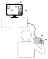
(Third embodiment)
In the third embodiment, an example in which the
本発明の入力装置は、ユーザが機器に対して命令を入力するための入力装置等に利用可能であり、特に、タッチパネルディスプレイの直感的な操作感を維持した操作感を実現したい場合等に有用である。 The input device of the present invention can be used as an input device for a user to input a command to a device, and is particularly useful when it is desired to realize an operational feeling while maintaining an intuitive operational feeling of a touch panel display. It is.
1 接触領域検知部
2 演算部
11 I/O
12 HDD
13 ROM
14 CPU
15 RAM
16 バス線
17 画像プロセッサ
18 VRAM
21 位置座標データ作成部
22 指先位置特定部
23 手画像データ保持部
24 GUIパーツ保持部
25 重畳画像作成部
26 操作内容判定部
27 コマンド送信部
41〜44 指先位置点
100 入力装置
50、64 入力部
51 カメラ
52、65 ユーザの手
53、62 表示部
54 選択メニュー
55、71 手画像
63 選択メニュー
66 手形状モデル
1 Contact
12 HDD
13 ROM
14 CPU
15 RAM
16
DESCRIPTION OF
Claims (13)
手を表す画像データである手画像データを予め保持する手画像データ保持部と、
前記操作対象機器に与える指示を割当てた複数のGUIパーツを予め保持するGUIパーツ保持部と、
前記ユーザが操作するための操作面を有し、当該操作面と前記ユーザの手との接触領域を検知する接触領域検知部と、
前記接触領域検知部が検知した前記接触領域に基づいて、前記操作面に現在接触している前記ユーザの手の指先位置を示す指先位置点を作成する位置座標データ作成部と、
前記指先位置点が所定数あるか否かを判定する指先位置特定部と、
前記指先位置点が所定数ある場合に、前記GUIパーツ保持部に保持された前記所定数のGUIパーツと、前記手画像データ保持部に保持された手画像データとを重畳させて、ユーザの操作に用いる操作画像を作成し、前記表示部に表示させる重畳画像作成部と、
前記所定数の指先位置点のいずれかがタップ操作された場合に、前記ユーザが行った操作内容を判定する操作内容判定部と、
前記操作内容判定部が判定したユーザの操作内容をコマンドに変換し、前記操作対象機器に送信するコマンド送信部とを備える、入力装置。 An input device that gives an operation target device a user instruction input using an operation image displayed on a display unit,
A hand image data holding unit for holding in advance hand image data which is image data representing a hand;
A GUI parts holding unit that holds in advance a plurality of GUI parts assigned instructions to be given to the operation target device;
A contact area detection unit that has an operation surface for the user to operate and detects a contact area between the operation surface and the user's hand;
A position coordinate data creation unit that creates a fingertip position point indicating a fingertip position of the user's hand that is currently in contact with the operation surface, based on the contact area detected by the contact area detection unit;
A fingertip position specifying unit that determines whether or not there are a predetermined number of fingertip position points;
When there are a predetermined number of fingertip position points, the predetermined number of GUI parts held in the GUI parts holding unit and the hand image data held in the hand image data holding unit are overlapped to perform user operation. An operation image to be used for creating a superimposed image creating unit to be displayed on the display unit;
An operation content determination unit that determines the operation content performed by the user when any of the predetermined number of fingertip position points is tapped;
An input device comprising: a command transmission unit that converts a user operation content determined by the operation content determination unit into a command and transmits the command to the operation target device.
前記接触領域検知部は、
X座標軸と垂直な方向に光を発する多数のX発光部と、当該多数のX発光部が発した光を受光する多数のX受光部と、
Y座標軸と垂直な方向に光を発する多数のY発光部と、当該多数のY発光部が発した光を受光する多数のY受光部とを備えることを特徴とする、請求項1に記載の入力装置。 When the area on the operation surface of the contact area detection unit is represented by the X coordinate and the Y coordinate,
The contact area detector is
A number of X light emitting units that emit light in a direction perpendicular to the X coordinate axis; a number of X light receiving units that receive light emitted by the plurality of X light emitting units;
2. The apparatus according to claim 1, comprising: a plurality of Y light emitting units that emit light in a direction perpendicular to the Y coordinate axis; and a plurality of Y light receiving units that receive light emitted from the plurality of Y light emitting units. Input device.
前記接触領域検知部は、
X座標軸と垂直な方向にストライプ状の電流を流すXストライプ状導電膜と、
Y座標軸と垂直な方向にストライプ状の電流を流すYストライプ状導電膜とを備えることを特徴とする、請求項1に記載の入力装置。 When the area on the operation surface of the contact area detection unit is represented by the X coordinate and the Y coordinate,
The contact area detector is
An X-striped conductive film that causes a striped current to flow in a direction perpendicular to the X-coordinate axis;
The input device according to claim 1, further comprising a Y-striped conductive film that causes a striped current to flow in a direction perpendicular to the Y coordinate axis.
前記操作内容判定部は、前記所定数の指先位置点のうち、前記タップ操作がされた指先位置点とのX座標が最も近い指先位置点に対応した指先を、前記タップ操作があった指先と特定することを特徴とする、請求項7又は8のいずれかに記載の入力装置。 When the longitudinal direction of the user's hand on the operation surface of the contact area detection unit is the direction of the Y coordinate axis, and the direction orthogonal to the Y coordinate axis is the direction of the X coordinate axis,
The operation content determination unit selects a fingertip corresponding to a fingertip position point having an X coordinate closest to the fingertip position point on which the tap operation has been performed among the predetermined number of fingertip position points as the fingertip on which the tap operation has been performed. The input device according to claim 7, wherein the input device is specified.
前記接触領域検知部は、
前記X座標軸と垂直な方向に光を発する多数のX発光部と、当該多数のX発光部が発した光を受光する多数のX受光部とを備えることを特徴とする、請求項1に記載の入力装置。 An area on the operation surface of the contact area detection unit is represented by an X coordinate and a Y coordinate, and the longitudinal direction of the user's hand on the operation surface of the contact area detection unit is a Y coordinate axis direction, which is orthogonal to the Y coordinate axis. If the direction is the direction of the X coordinate axis,
The contact area detector is
2. The apparatus according to claim 1, further comprising: a plurality of X light emitting units that emit light in a direction perpendicular to the X coordinate axis; and a plurality of X light receiving units that receive light emitted from the plurality of X light emitting units. Input device.
前記接触領域検知部は、
前記X座標軸と垂直な方向にストライプ状の電流を流すXストライプ状導電膜を備えることを特徴とする、請求項1に記載の入力装置。 An area on the operation surface of the contact area detection unit is represented by an X coordinate and a Y coordinate, and the longitudinal direction of the user's hand on the operation surface of the contact area detection unit is a Y coordinate axis direction, which is orthogonal to the Y coordinate axis. If the direction is the direction of the X coordinate axis,
The contact area detector is
The input device according to claim 1, further comprising an X-striped conductive film that causes a striped current to flow in a direction perpendicular to the X-coordinate axis.
前記操作面と前記ユーザの手との接触領域を検知するステップと、
前記検知した接触領域に基づいて、前記操作面に現在接触している前記ユーザの手の指先位置を示す指先位置点を作成するステップと、
前記指先位置点が所定数あるか否かを判定するステップと、
前記指先位置点が所定数ある場合に、予め保持された前記操作対象機器に与える指示を割当てた前記所定数のGUIパーツと、予め保持された手を表す画像データである手画像データとを重畳させて、ユーザの操作に用いる操作画像を作成し、前記表示部に表示させるステップと、
前記所定数の指先位置点のいずれかがタップ操作された場合に、前記ユーザが行った操作内容を判定するステップと、
前記判定したユーザの操作内容をコマンドに変換し、前記操作対象機器に送信するステップとを備える、入力方法。 An input method that uses an operation image displayed on a display unit to give a user instruction input to an operation surface to an operation target device,
Detecting a contact area between the operation surface and the user's hand;
Creating a fingertip position point indicating a fingertip position of the user's hand currently in contact with the operation surface based on the detected contact area;
Determining whether there are a predetermined number of fingertip position points;
When there are a predetermined number of fingertip position points, the predetermined number of GUI parts to which an instruction to be given to the operation target device is held in advance and hand image data that is image data representing a hand held in advance are superimposed. And creating an operation image used for a user operation and displaying the operation image on the display unit;
A step of determining an operation content performed by the user when any of the predetermined number of fingertip position points is tapped;
An input method comprising: converting the determined user operation content into a command and transmitting the command to the operation target device.
Priority Applications (1)
| Application Number | Priority Date | Filing Date | Title |
|---|---|---|---|
| JP2008235483A JP5027084B2 (en) | 2008-09-12 | 2008-09-12 | Input device and input method |
Applications Claiming Priority (1)
| Application Number | Priority Date | Filing Date | Title |
|---|---|---|---|
| JP2008235483A JP5027084B2 (en) | 2008-09-12 | 2008-09-12 | Input device and input method |
Publications (2)
| Publication Number | Publication Date |
|---|---|
| JP2010067217A true JP2010067217A (en) | 2010-03-25 |
| JP5027084B2 JP5027084B2 (en) | 2012-09-19 |
Family
ID=42192713
Family Applications (1)
| Application Number | Title | Priority Date | Filing Date |
|---|---|---|---|
| JP2008235483A Expired - Fee Related JP5027084B2 (en) | 2008-09-12 | 2008-09-12 | Input device and input method |
Country Status (1)
| Country | Link |
|---|---|
| JP (1) | JP5027084B2 (en) |
Cited By (1)
| Publication number | Priority date | Publication date | Assignee | Title |
|---|---|---|---|---|
| JP2014013518A (en) * | 2012-07-05 | 2014-01-23 | Kyocera Corp | Portable terminal, braille input method, and braille input program |
Citations (2)
| Publication number | Priority date | Publication date | Assignee | Title |
|---|---|---|---|---|
| JP2003099200A (en) * | 2001-09-26 | 2003-04-04 | Clarion Co Ltd | Information equipment |
| JP2004062867A (en) * | 2002-06-03 | 2004-02-26 | Fuji Xerox Co Ltd | Function controller and its method |
-
2008
- 2008-09-12 JP JP2008235483A patent/JP5027084B2/en not_active Expired - Fee Related
Patent Citations (2)
| Publication number | Priority date | Publication date | Assignee | Title |
|---|---|---|---|---|
| JP2003099200A (en) * | 2001-09-26 | 2003-04-04 | Clarion Co Ltd | Information equipment |
| JP2004062867A (en) * | 2002-06-03 | 2004-02-26 | Fuji Xerox Co Ltd | Function controller and its method |
Cited By (1)
| Publication number | Priority date | Publication date | Assignee | Title |
|---|---|---|---|---|
| JP2014013518A (en) * | 2012-07-05 | 2014-01-23 | Kyocera Corp | Portable terminal, braille input method, and braille input program |
Also Published As
| Publication number | Publication date |
|---|---|
| JP5027084B2 (en) | 2012-09-19 |
Similar Documents
| Publication | Publication Date | Title |
|---|---|---|
| US9411424B2 (en) | Input device for operating graphical user interface | |
| CN101375235B (en) | Information processing device | |
| KR101453628B1 (en) | A user interface | |
| WO2013018480A1 (en) | User interface device comprising touch pad for shrinking and displaying source image within screen capable of touch input, input processing method and program | |
| JP4818036B2 (en) | Touch panel control device and touch panel control method | |
| JP2006072854A (en) | Input device | |
| JP2009157908A (en) | Information display terminal, information display method, and program | |
| JP2016009300A (en) | Vehicle input device and vehicle cockpit module | |
| JP3744116B2 (en) | Display input device | |
| WO2011055459A1 (en) | Information processing device, method thereof, and display device | |
| JP4924164B2 (en) | Touch input device | |
| JP2008065504A (en) | Touch panel control device and touch panel control method | |
| JPH11259237A (en) | Picture display device | |
| WO2021163020A1 (en) | Non-contact gesture commands for touch screens | |
| JP5790578B2 (en) | Display system, display device, and operation device | |
| US20150009136A1 (en) | Operation input device and input operation processing method | |
| WO2012026322A1 (en) | Method and device for editing layout of objects | |
| JP5027084B2 (en) | Input device and input method | |
| JP2010129026A (en) | Input device | |
| JP5062898B2 (en) | User interface device | |
| JP2012146017A (en) | Electronic blackboard system, electronic blackboard system control method, program and recording medium therefor | |
| US20150309601A1 (en) | Touch input system and input control method | |
| WO2021225044A1 (en) | Information processing device, information processing method based on user input operation, and computer program for executing said method | |
| WO2014181587A1 (en) | Portable terminal device | |
| JP2009184551A (en) | On-vehicle equipment input device |
Legal Events
| Date | Code | Title | Description |
|---|---|---|---|
| A621 | Written request for application examination |
Free format text: JAPANESE INTERMEDIATE CODE: A621 Effective date: 20110317 |
|
| RD02 | Notification of acceptance of power of attorney |
Free format text: JAPANESE INTERMEDIATE CODE: A7422 Effective date: 20110826 |
|
| A977 | Report on retrieval |
Free format text: JAPANESE INTERMEDIATE CODE: A971007 Effective date: 20120116 |
|
| A131 | Notification of reasons for refusal |
Free format text: JAPANESE INTERMEDIATE CODE: A131 Effective date: 20120123 |
|
| A521 | Request for written amendment filed |
Free format text: JAPANESE INTERMEDIATE CODE: A523 Effective date: 20120301 |
|
| TRDD | Decision of grant or rejection written | ||
| A01 | Written decision to grant a patent or to grant a registration (utility model) |
Free format text: JAPANESE INTERMEDIATE CODE: A01 Effective date: 20120619 |
|
| A01 | Written decision to grant a patent or to grant a registration (utility model) |
Free format text: JAPANESE INTERMEDIATE CODE: A01 |
|
| A61 | First payment of annual fees (during grant procedure) |
Free format text: JAPANESE INTERMEDIATE CODE: A61 Effective date: 20120621 |
|
| FPAY | Renewal fee payment (event date is renewal date of database) |
Free format text: PAYMENT UNTIL: 20150629 Year of fee payment: 3 |
|
| R150 | Certificate of patent or registration of utility model |
Free format text: JAPANESE INTERMEDIATE CODE: R150 |
|
| S111 | Request for change of ownership or part of ownership |
Free format text: JAPANESE INTERMEDIATE CODE: R313113 |
|
| R350 | Written notification of registration of transfer |
Free format text: JAPANESE INTERMEDIATE CODE: R350 |
|
| LAPS | Cancellation because of no payment of annual fees |