JP2010065745A - Plug-in type pipe joint - Google Patents
Plug-in type pipe joint Download PDFInfo
- Publication number
- JP2010065745A JP2010065745A JP2008231583A JP2008231583A JP2010065745A JP 2010065745 A JP2010065745 A JP 2010065745A JP 2008231583 A JP2008231583 A JP 2008231583A JP 2008231583 A JP2008231583 A JP 2008231583A JP 2010065745 A JP2010065745 A JP 2010065745A
- Authority
- JP
- Japan
- Prior art keywords
- connecting pipe
- plug
- lip packing
- joint
- joint body
- Prior art date
- Legal status (The legal status is an assumption and is not a legal conclusion. Google has not performed a legal analysis and makes no representation as to the accuracy of the status listed.)
- Granted
Links
- 238000012856 packing Methods 0.000 claims abstract description 71
- 230000002093 peripheral effect Effects 0.000 claims abstract description 38
- 125000006850 spacer group Chemical group 0.000 claims abstract description 27
- 238000011144 upstream manufacturing Methods 0.000 claims abstract description 25
- 238000003780 insertion Methods 0.000 claims description 37
- 230000037431 insertion Effects 0.000 claims description 37
- XLYOFNOQVPJJNP-UHFFFAOYSA-N water Substances O XLYOFNOQVPJJNP-UHFFFAOYSA-N 0.000 abstract description 21
- 238000007789 sealing Methods 0.000 abstract description 10
- 230000002265 prevention Effects 0.000 description 9
- 229910000963 austenitic stainless steel Inorganic materials 0.000 description 3
- 230000006835 compression Effects 0.000 description 3
- 238000007906 compression Methods 0.000 description 3
- 230000000694 effects Effects 0.000 description 3
- 239000000463 material Substances 0.000 description 3
- 238000000034 method Methods 0.000 description 3
- 238000006748 scratching Methods 0.000 description 3
- 239000004734 Polyphenylene sulfide Substances 0.000 description 2
- 229920006351 engineering plastic Polymers 0.000 description 2
- 239000002184 metal Substances 0.000 description 2
- 229920000069 polyphenylene sulfide Polymers 0.000 description 2
- 229910001220 stainless steel Inorganic materials 0.000 description 2
- 239000010935 stainless steel Substances 0.000 description 2
- 229910000906 Bronze Inorganic materials 0.000 description 1
- 101100385401 Caenorhabditis elegans kin-10 gene Proteins 0.000 description 1
- ZAMOUSCENKQFHK-UHFFFAOYSA-N Chlorine atom Chemical compound [Cl] ZAMOUSCENKQFHK-UHFFFAOYSA-N 0.000 description 1
- 229920002943 EPDM rubber Polymers 0.000 description 1
- BZHJMEDXRYGGRV-UHFFFAOYSA-N Vinyl chloride Chemical compound ClC=C BZHJMEDXRYGGRV-UHFFFAOYSA-N 0.000 description 1
- 150000001336 alkenes Chemical class 0.000 description 1
- 239000010974 bronze Substances 0.000 description 1
- 229910052801 chlorine Inorganic materials 0.000 description 1
- 239000000460 chlorine Substances 0.000 description 1
- 238000010276 construction Methods 0.000 description 1
- KUNSUQLRTQLHQQ-UHFFFAOYSA-N copper tin Chemical compound [Cu].[Sn] KUNSUQLRTQLHQQ-UHFFFAOYSA-N 0.000 description 1
- 238000005260 corrosion Methods 0.000 description 1
- 230000007797 corrosion Effects 0.000 description 1
- 238000004132 cross linking Methods 0.000 description 1
- 229920003020 cross-linked polyethylene Polymers 0.000 description 1
- 239000004703 cross-linked polyethylene Substances 0.000 description 1
- 150000001993 dienes Chemical class 0.000 description 1
- 229920001971 elastomer Polymers 0.000 description 1
- -1 ethylene, propylene Chemical group 0.000 description 1
- 229920001973 fluoroelastomer Polymers 0.000 description 1
- 238000005495 investment casting Methods 0.000 description 1
- 229910001105 martensitic stainless steel Inorganic materials 0.000 description 1
- 239000000178 monomer Substances 0.000 description 1
- JRZJOMJEPLMPRA-UHFFFAOYSA-N olefin Natural products CCCCCCCC=C JRZJOMJEPLMPRA-UHFFFAOYSA-N 0.000 description 1
- 239000004033 plastic Substances 0.000 description 1
- 229920003023 plastic Polymers 0.000 description 1
- 239000011347 resin Substances 0.000 description 1
- 229920005989 resin Polymers 0.000 description 1
- 239000000126 substance Substances 0.000 description 1
- 229920001897 terpolymer Polymers 0.000 description 1
Images


Abstract
Description
本発明は、給水又は給湯用ステンレス鋼管などの配管をワンタッチで接続するために使用される差込式管継手に関する。 The present invention relates to a plug-in type pipe joint used for connecting a pipe such as a stainless steel pipe for water supply or hot water supply with one touch.
この種のワンタッチ方式の差込式管継手として、先に、本出願人により、図8〜図10に示すような差込式管継手1を提案した(特願2007−164993)。その差込式管継手1は、接続管11の端部を受け入れる受口部12を有し、かつ該受口部12の内周に接続管差込み方向上流側に向かって次第に窄まり状のテーパー面13を形成している継手本体2の内部に、受口部12から継手本体内奥に向かって順に、外径部がテーパー面13に内接し内径部が接続管11の外周面に係合される抜止部材3と、この抜止部材3を保持するカラー15と、抜止部材3をカラー15ごとテーパー面13に向かって押圧付勢する弾性部材4と、弾性部材4の接続管差込み方向下流側端部を保持する環状のスペーサー17と、接続管11の外周面に密着するリップパッキン5とを収容してある。
As this type of one-touch plug-in pipe joint, the present applicant has previously proposed a plug-in
また、継手本体2内には、リップパッキン5の内径部に配置され接続管11の末端に外嵌可能な傷付き防止スリーブ7とを備えており、傷付き防止スリーブ7は、図10のように接続管11が所定長さにまで差し込まれるに伴い該接続管11の末端で継手本体2の内奥に向かって押し込まれてリップパッキン5から抜け出るようにしてある。リップパッキン5は、リング状部5aと、このリング状部5aの内周から径方向内方へ突設するリップ部5bを有する形に形成され、自由状態においてリップ部5bの内径は接続管11の外径よりも小さい寸法に形成しており、リップパッキン5のリップ部5bは傷付き防止スリーブ7の抜け出しに伴い拡径変形して接続管11の外周面に密着するようにしてある。
Further, the
このような構成の差込式管継手によれば、継手本体2の内部に接続管11の外周面に係合する抜止部材3を収容しているので、接続管11を受口部12から差し込むだけのワンタッチ操作で抜止め状に接続できる。
また、継手本体2内のリップパッキン5と抜止部材3との間に、抜止部材3を受口部12の内周に向かって押圧付勢する弾性部材4を収容配置し、受口部12の内周に、抜止部材3の外径部が内接するテーパー面13を接続管差込み方向上流側に向かって窄まり状に形成しているので、図10のように接続管11が完全に差し込まれると、抜止部材3は弾性部材4により受口部12のテーパー面13に押し付けられると共に、そのテーパー面13によって抜止部材3が縮径して接続管11の外周面に係合されることにより、接続管11の確実な抜止め状態が得られる。
また、接続管11の差込み後、接続管11に引き抜き力が加えられると、接続管11と同行する抜止部材3の外径部が受口部12のテーパー面13と当接することにより、抜止部材3が径方向内方へ移動して、接続管11の外周面への係合力が増す。これにより接続管11の抜け出しが確実に阻止される。
According to the plug-in type pipe joint having such a configuration, the retaining
An
In addition, when a pulling force is applied to the connecting
リップパッキン5のリップ部5bが径方向内方に向かって突設して接続管11の外周面に圧縮状に密着していると、継手本体2内を流れる水が継手本体2の内周と接続管11の末端外周との間からリップパッキン5にまで流れ込んできてもその水圧によってリップ部5bを接続管11の外周面に押し付けるというシール圧が発生し、このため単一のリップパッキン5でもってシール機能を効果的に発揮する。
また、リップパッキン5のリップ部5bは、接続管11の小さい差込み荷重で接続管11の外周面との摺接作用により容易に変形させることができるので、接続管11を差込み操作し易くする。
When the
Further, the
接続管11の末端に外嵌可能な傷付き防止スリーブ7を備えているので、接続管11の切断に際し切断端面に多少の外側のエッジが発生しそれを除去する加工を怠っても、また接続管11が斜めに差込まれても該接続管11の端部の外側のエッジ等でリップパッキン5を傷付けることなく施工できる。
Since the
しかしながら、上記差込式管継手では、リップパッキン5のリング状部5aの接続管差込み方向上流側端面5c、および該端面5cに当接するスペーサー17の接続管差込み方向下流側端面17aはそれぞれ、継手本体2の軸方向に直交する垂直面に形成されている。このため、継手本体2内を流れる水が継手本体2の内周と接続管11の末端外周との間からリップパッキン5にまで流れ込んでくると、図10に示す状態のリップパッキン5は、その水圧(内圧)Pを受けて図12のようにスペーサー17を弾性部材4の弾力に抗して接続管差込み方向上流側の方向へ押し動かすが、このときリング状部5aの接続管差込み方向上流側端部がスペーサー17の接続管差込み方向下流側端面17aを強く押圧接当するに伴いリング状部5aの接続管差込み方向上流側端部が図13に破線で示すように継手本体2の内周面2aから離反する径方向内方(矢印A方向)に変位する作用を受け、これによりリング状部5aの接続管差込み方向上流側端部の外径部と継手本体2の内周面2aとの面圧が低下し、リップパッキン5によるシール性能を低下し、水漏れが発生するという問題があった。
However, in the plug-in type pipe joint, the
本発明は、このような問題点を解消するためになされたものであり、その目的とするところは、上記のような、抜止部材、カラー、弾性部材、スペーサー、およびリップパッキンを収容した差込式管継手において、スペーサーの断面形状に工夫を凝らすことによりリップパッキンによるシール性能の向上を図れて水漏れ防止を全うできる差込式管継手を提供することにある。 The present invention has been made in order to solve such problems, and the object of the present invention is to insert the retaining member, collar, elastic member, spacer, and lip packing as described above. An object of the present invention is to provide a plug-in type pipe joint capable of improving water-leakage prevention by improving the sealing performance by lip packing by devising the cross-sectional shape of the spacer.
本発明は、請求項1に記載のように、その発明の内容を理解しやすくするために図1〜図7に付した符号を参照して説明すると、少なくとも一端部に接続管(31)の端部を受け入れる受口部(32)を有し、かつ該受口部(32)の内周に接続管差込み方向上流側に向かって窄まり状のテーパー面(33)を形成している継手本体(21)の内部に、受口部(32)から継手本体内奥に向かって順に、外径部がテーパー面(33)に内接し内径部が接続管(31)の外周面に係合される抜止部材(23)と、この抜止部材(23)を保持するカラー(36)と、抜止部材(23)をカラー(36)ごとテーパー面(33)に向かって押圧付勢する弾性部材(24)と、弾性部材(24)の接続管差込み方向下流側端部を保持する環状のスペーサー(38)と、接続管(31)の外周面に密着するリップパッキン(25)とを収容しており、前記リップパッキン(25)はリング状部(25a)と、このリング状部(25a)の内周から径方向内方へ突設されたリップ部(25b)とを有する形に形成している差込式管継手において、前記リング状部(25a)の接続管差込み方向上流側端部に当接する前記スペーサー(38)の接続管差込み方向下流側端面(38a)は、接続管差込み方向下流側に向かって次第に窄まり状のテーパー面(38t)に形成していることに特徴を有するものである。
As described in
上記構成のように、リップパッキン(25)のリング状部(25a)の接続管差込み方向上流側端部に当接するスペーサー(38)の接続管差込み方向下流側端面(38a)は、接続管差込み方向下流側に向かって次第に窄まり状のテーパー面(38t)に形成した構成を採用することにより、不測にも継手本体(21)内を流れる水が継手本体(21)の内周と接続管11の末端外周との間からリップパッキン5にまで流れ込んで来た場合にはリップパッキン(25)はその水圧(内圧)を受けてスペーサー(38)を弾性部材(24)の弾力に抗し接続管差込み方向上流側の方向へ押し動かしながら、リング状部(25a)の接続管差込み方向上流側端部をスペーサー(38)のテーパー面(38t)に強く当接し、この当接作用によりリング状部(25a)の接続管差込み方向上流側端部が継手本体(21)の内周面(39)に向かって変位される作用を受けるので、リング状部(25a)の接続管差込み方向上流側端部の外径部と継手本体(21)の内周面(39)との面圧が高まり、リップパッキン(25)によるシール機能をアップすることができる。
As described above, the downstream end surface (38a) of the spacer (38) in contact with the upstream end of the ring-shaped portion (25a) of the lip packing (25) in the connecting tube insertion direction is inserted into the connecting tube. By adopting a configuration in which the tapered surface (38t) is gradually narrowed toward the downstream side in the direction, water unexpectedly flowing in the joint body (21) and the inner circumference of the joint body (21) and the connecting pipe When the lip packing (25) flows into the lip packing 5 from between the outer periphery of the
本発明によれば、スペーサーの接続管差込み方向下流側端面に、接続管差込み方向下流側に向かって次第に窄まり状のテーパー面を形成するという簡単な手段で、リップパッキンが内圧によりスペーサーに向かって押し動かされるときもリップパッキンによるシール性能を向上できて水漏れを防止できるという利点がある。 According to the present invention, the lip packing is directed toward the spacer by the internal pressure by a simple means of forming a tapered surface gradually narrowing toward the downstream side in the connecting pipe insertion direction on the downstream end face of the spacer in the connecting pipe insertion direction. Even when pushed and moved, there is an advantage that the sealing performance by the lip packing can be improved and water leakage can be prevented.
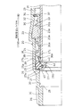
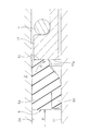
図1は本発明の一実施例の差込式管継手を接続管差込み前の状態で示す半欠截断面図、図2は同差込式管継手を接続管差込み途中の状態で示す半欠截断面図、図3は同差込式管継手を接続管差し込み後の状態で示す半欠截断面図、図4は同差込式管継手の傷付き防止スリーブの斜視図、図5は同差込式管継手のスペーサーの半欠截断面図、図6は同差込式管継手内を流れる水がリップパッキンにまで流れ込んで来た場合の状態を示す半欠截断面図、図7は図6におけるリップパッキンの作用図である。 FIG. 1 is a cross-sectional view of a half-notch showing an insertion-type pipe joint according to an embodiment of the present invention before the connection pipe is inserted, and FIG. Fig. 3 is a cross-sectional view of the plug-in pipe joint after it is inserted into the connecting pipe. Fig. 4 is a perspective view of the damage prevention sleeve of the plug-in pipe fitting. FIG. 6 is a half cutaway cross-sectional view of the plug-in pipe joint spacer, FIG. 6 is a half cutaway cross-sectional view showing a state in which water flowing through the plug-in pipe fitting flows into the lip packing, and FIG. It is an effect | action figure of the lip packing in FIG.
図1〜図3に示すように、本発明の一実施例を示す差込式管継手20は、両端部が開口した筒形状を有する継手本体21と、この継手本体21の内部に収容配置される抜止部材23、弾性部材24、リップパッキン25、および傷付き防止スリーブ27等を備えている。
As shown in FIGS. 1 to 3, a plug-in
継手本体21は、耐食性及び剛性を必要とするので、例えばSCS材や青銅材により精密鋳造の手法等により製造する。そして、図1のように、継手本体21は、軸方向中央付近に第1段部28を設け、この第1段部28をはさんで一側に大径部29を、他側に小径の流路30を形成し、大径部29の開口端部、すなわち継手本体21の軸方向一端部に接続管31の端部が差し込まれる受口部32を形成し、他端部の外周に接続用雄ねじ26を形成している。受口部32の開口端側の内周には接続管差込み方向上流側に向かって窄まり状のテーパー面33と、テーパー面33の受口部外方側端に円周溝34を形成している。受口部32内の第1段部28とテーパー面33との間の中間部内周には第1段部28より径大の第2段部35を設けている。
Since the
図1のように、受口部32の内部には、テーパー面33に内接する抜止部材23と、この抜止部材23を保持するカラー36と、抜止部材23をカラー36ごとテーパー面33に向かって押圧付勢する弾性部材24とが収容配置されている。抜止部材23は、接続管31より硬質の材料、例えば接続管31がオーステナイト系ステンレス鋼(SUS304)の場合は、マルテンサイト系ステンレス鋼(SUS420)で形成すればよい。継手本体21の円周溝34にはストッパーリング37が嵌合されてその内径部でカラー36が受口部外方へ抜け出るのを防止している。ストッパーリング37はオーステナイト系ステンレス鋼(SUS304)等で形成することができる。
As shown in FIG. 1, inside the
弾性部材24は圧縮コイルばね等からなり、この弾性部材24の後端部はカラー36の前端の段部36aに係合し、同弾性部材24の前端部はリップパッキン25に隣接配置する断面L形の環状のスペーサー38に係合している。弾性部材24として圧縮コイルバネを使用する場合は、この部材をオーステナイト系ステンレス鋼(SUS304)等で形成することができる。
The
リップパッキン25は、オレフィン系ゴム製パッキン等で弾性変形自在に形成し、特に耐塩素、耐熱性に優れたエチレンとプロピレン及び架橋用ジエンモノマーとの3元共重合体であるEPDMで形成することが好ましく、また耐熱性とともに耐薬品性にも優れたFKM(フッ素ゴム)などで形成することもできる。そして、図1のように、リップパッキン25はリング状部25aと、このリング状部25aの内周から径方向内方に突設する弾性変形自在な環状のリップ部25bを有する形に形成され、自由状態においてリップ部25bの内径は接続管31の外径よりも小さい寸法に形成している。リップパッキン25は図1のように断面V形状ないしU形状に形成する以外に、断面L形状等に形成することもできる。このリップパッキン25は受口部32内の第2段部35に収容配置する。
The lip packing 25 is formed of an olefin rubber packing or the like so as to be elastically deformable. In particular, the lip packing 25 is formed of EPDM which is a terpolymer of ethylene, propylene and a diene monomer for crosslinking, which is excellent in chlorine resistance and heat resistance. Further, it can be formed of FKM (fluoro rubber) having excellent heat resistance and chemical resistance. As shown in FIG. 1, the lip packing 25 is formed to have a ring-shaped
傷付き防止スリーブ27はPP、PB等プラスチックや金属などで形成し、図1、図4に示すように、内径が接続管31の内径と略同一径もしくは該内径よりも小さく、外径が継手本体21内の第1段部28と第2段部35との間の内周面39の内径よりも小さく形成されたパッキン保持筒部27aと、このパッキン保持筒部27aの後端側に一体に連設され、内径が接続管31の外径よりも大きく形成されて接続管31の末端に外嵌可能な薄肉の管端部受け筒部27bとを有する形に形成されている。パッキン保持筒部27aの内周面と管端部受け筒部27bの内周面との間には、接続管31の末端が当接する段部40を形成している。パッキン保持筒部27aの外周には、自由状態(リップパッキン25が拡径するように変形されておらず圧縮応力又は引張応力が作用していない状態)のリップパッキン25のリップ部25bが嵌まり込む断面略V形状の凹溝41を形成している。管端部受け筒部27bの後端部27cは後方へ漸次拡径するラッパ状に形成し、これにより接続管31の差込み時に該接続管31の末端が管端部受け筒部27bの後端部27cに引っ掛かることなくスムーズに差し込まれるようになしている。管端部受け筒部27bにはスリット42を円周方向に所定間隔置きに設けている。パッキン保持筒部27aの先端部外周にはアール又は先窄まりテーパー43を付けて、継手本体21内の内周面39に差し込み易くしている。
The
カラー36は、架橋ポリエチレンなどの汎用エンジニアリングプラスチックや、優れた耐熱性を有するPPS(ポリフェニレンサルファイド)などの特殊エンジニアリングプラスチックで形成し、図1に示すように、複数個の保持穴36bを円周方向に所定間隔置きに有し、各保持穴36bに抜止部材23が嵌着されている。各抜止部材23の内径側には複数(図示例では2個)の係合歯23aを形成している。
The
上記リップパッキン25のリング状部25aの接続管差込み方向上流側端部に当接するスペーサー38の接続管差込み方向下流側端面38aは、図1、図5に示すように、接続管差込み方向下流側に向かって次第に窄まり状のテーパー面38tに形成している。テーパー面38tは、例えば、スペーサー38の垂直な接続管差込み方向下流側端面38aとの成す角度θを20度とする。
As shown in FIGS. 1 and 5, the
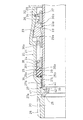
次に、上記差込式管継手20による接続管31の接続施工手順を図1〜図3を参照にして説明する。
Next, the connection construction procedure of the
先ず、接続管31の接続に際しては、図2に示すように、継手本体21の受口部32に接続管31を差し込み、その接続管31の末端を傷付き防止スリーブ27の管端部受け筒部27bに差し込んで傷付き防止スリーブ27内の段部40に当接させる。この接続管31の差込みに伴い抜止部材23は受口部32のテーパー面33に沿って継手本体21の内奥方向に移動し、かつ係合歯23aが接続管31の外周面に近接する。この状態で接続管31を引き抜く方向に外力が加わったとしても、図3のように受口部32のテーパー面33に当接する抜止部材23の係合歯23aが接続管31の外周面に係合するので、接続管31が抜け出ることはない。
また、この接続管31の差込み時にはリップパッキン25と接続管31の末端との間に傷付き防止スリーブ27が介在した状態にあり、この状態で接続管31の末端の端面はリップパッキン25と非接触の状態で継手本体21の奥まで差し込まれるので、接続管31の末端の端面に外側のエッジが生じていてもその外側のエッジでリップパッキン25が傷付けられることはなく、また接続管31が斜めに差込まれてもその末端でリップパッキン25が傷付けられることもなく、リップパッキン25の損傷による水漏れは生じない。
First, when connecting the
Further, when the connecting
接続管31を更に深く差し込むと、図2の差込み途中過程を経て、図3に示すように継手本体21と接続管31とのシール接続状態が得られる。すなわち、図2に示す状態に接続管31が継手本体21内の途中まで差し込まれると、接続管31は傷付き防止スリーブ27を継手本体内奥方向へ押込み、パッキン保持筒部27aはリップパッキン25と同位置に来る。
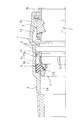
更に、接続管31が差し込まれると、接続管31は、図3に示すように、傷付き防止スリーブ27がパッキン保持筒部27aを継手本体21内の第1段部28に当接するとともに管端部受け筒部27bをリップパッキン25よりも継手本体内奥方向に押込む。この過程において、傷付き防止スリーブ27は、リップパッキン25のリップ部25bを継手本体内奥方向に変向しながら移動しリップパッキン25から外れ、接続管31の差込みが完了した図3の状態では、リップパッキン25のリップ部25bは接続管31の外周面に圧縮状に密着して接続管31の外周面と継手本体21の内周面39との間を密封シールする状態が得られるとともに、抜止部材23の係合歯23aが接続管31の外周面に係合した抜止め状態が得られる。
When the
Further, when the connecting
リップパッキン25のリップ部25bが継手本体21の内奥方向に向いた状態で接続管31の外周面に圧縮状に密着していると、継手本体21内を流れる水が継手本体21の内周と傷付き防止スリーブ27との間あるいは接続管31の末端と傷付き防止スリーブ27との間からリップパッキン25にまで流れ込んできてもその水圧によってリップ部25bを接続管31の外周面に押し付けるというシール圧が発生し、このため単一のリップパッキン25でもってシール機能を効果的に発揮する。
また、リップパッキン25のリップ部25bは、接続管31の小さい差込み荷重で傷付き防止スリーブ27の凹溝41の内面及び管端部受け筒部27bの外周面との摺接作用により容易に変形させることができるので、接続管31を差込み操作し易い。
If the
Further, the
接続管31の差込み完了後、該接続管31を抜き出し方向に引っ張ると、接続管31と同行する抜止部材23の外径部がテーパー面33の窄まり側に当接することにより、抜止部材23が径方向内方へ移動して係合歯23aが接続管31の外周面へ食い込み係合力を増す。これにより接続管31の抜け出しが確実に阻止される。
After the
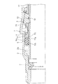
いま、不測にも継手本体21内を流れる水が継手本体21の内周と接続管31の末端外周との間からリップパッキン25にまで流れ込んでくると、図6、図7のように、リップパッキン25は、その水圧Pを受けて、スペーサー38を弾性部材24の弾力に抗しながら接続管差込み方向上流側の方向へ押し動かしながら、リング状部25aの接続管差込み方向上流側端部をスペーサー38のテーパー面38tに当接し、この当接作用によりリング状部25aの接続管差込み方向上流側端部が継手本体21の内周面39に向かって矢印B方向に変位される作用を受けるので(図7中、dは矢印B方向への変形量を示す)、リング状部25aの接続管差込み方向上流側端部の外径部と継手本体21の内周面39との面圧が高まり、リップパッキン25によるシール機能をアップする。したがって、継手本体21内を流れる水がリップパッキン25のリング状部25aの接続管差込み方向上流側端部の外径部と継手本体21の内周面39との間から漏れるのを確実に防止できる。
If water that flows in the
なお、上記実施例では、継手本体21の一方の側に接続用雄ねじ26を形成した雄ねじアダプター差込式管継手について記述したが、本発明はこれに限られず、他の構造、例えば、左右対称のソケット形差込式管継手、エルボ型差込式管継手等にも適用できることは勿論である。また、接続管31としては、ステンレス鋼管等の金属管に限られず、樹脂製の接続管、例えば塩化ビニール製の接続管などにも適用することができる。
In the above-described embodiment, the male thread adapter plug-in type pipe joint in which the male thread for
20 差込式管継手
21 継手本体
23 抜止部材
24 弾性部材
25 リップパッキン
25a リング状部
25b リップ部
31 接続管
32 受口部
33 テーパー面
36 カラー
38 スペーサー
38a 接続管差込み方向下流側端面
38t テーパー面
39 内周面
DESCRIPTION OF
Claims (1)
前記リング状部の接続管差込み方向上流側端部に当接する前記スペーサーの接続管差込み方向下流側端面は、接続管差込み方向下流側に向かって次第に窄まり状のテーパー面に形成していることを特徴とする、差込式管継手。 A joint body having a receiving portion for receiving the end portion of the connecting pipe at least at one end portion and forming a tapered surface gradually narrowing toward the upstream side in the connecting tube insertion direction on the inner periphery of the receiving portion. A retaining member in which the outer diameter portion is inscribed in the tapered surface and the inner diameter portion is engaged with the outer peripheral surface of the connecting pipe in order from the receiving portion toward the inner depth of the joint body, and the retaining member. A collar to hold, an elastic member that presses and urges the retaining member together with the collar toward the tapered surface, an annular spacer that holds the downstream end of the elastic member in the connecting pipe insertion direction, and an outer periphery of the connecting pipe The lip packing is formed in a shape having a ring-shaped portion and a lip portion protruding radially inward from the inner periphery of the ring-shaped portion. For plug-in fittings,
The downstream end surface of the spacer in contact with the upstream side in the connecting pipe insertion direction of the ring-shaped part is formed as a tapered surface gradually narrowing toward the downstream side in the connecting pipe insertion direction. Plug-in type pipe joint characterized by
Priority Applications (1)
| Application Number | Priority Date | Filing Date | Title |
|---|---|---|---|
| JP2008231583A JP5401063B2 (en) | 2008-09-10 | 2008-09-10 | Plug-in fittings |
Applications Claiming Priority (1)
| Application Number | Priority Date | Filing Date | Title |
|---|---|---|---|
| JP2008231583A JP5401063B2 (en) | 2008-09-10 | 2008-09-10 | Plug-in fittings |
Publications (2)
| Publication Number | Publication Date |
|---|---|
| JP2010065745A true JP2010065745A (en) | 2010-03-25 |
| JP5401063B2 JP5401063B2 (en) | 2014-01-29 |
Family
ID=42191492
Family Applications (1)
| Application Number | Title | Priority Date | Filing Date |
|---|---|---|---|
| JP2008231583A Active JP5401063B2 (en) | 2008-09-10 | 2008-09-10 | Plug-in fittings |
Country Status (1)
| Country | Link |
|---|---|
| JP (1) | JP5401063B2 (en) |
Cited By (2)
| Publication number | Priority date | Publication date | Assignee | Title |
|---|---|---|---|---|
| JP2012031947A (en) * | 2010-07-30 | 2012-02-16 | Jfe Pipe Fitting Mfg Co Ltd | Insertion type pipe joint |
| JP2013245744A (en) * | 2012-05-25 | 2013-12-09 | Jfe Pipe Fitting Mfg Co Ltd | Insertion type pipe joint |
Citations (3)
| Publication number | Priority date | Publication date | Assignee | Title |
|---|---|---|---|---|
| JP2002295762A (en) * | 2001-04-02 | 2002-10-09 | Nitta Moore Co | Pipe joint |
| JP2008190676A (en) * | 2007-02-07 | 2008-08-21 | Hitachi Metals Ltd | Pipe joint |
| JP2008190590A (en) * | 2007-02-02 | 2008-08-21 | Hitachi Metals Ltd | Pipe joint |
-
2008
- 2008-09-10 JP JP2008231583A patent/JP5401063B2/en active Active
Patent Citations (3)
| Publication number | Priority date | Publication date | Assignee | Title |
|---|---|---|---|---|
| JP2002295762A (en) * | 2001-04-02 | 2002-10-09 | Nitta Moore Co | Pipe joint |
| JP2008190590A (en) * | 2007-02-02 | 2008-08-21 | Hitachi Metals Ltd | Pipe joint |
| JP2008190676A (en) * | 2007-02-07 | 2008-08-21 | Hitachi Metals Ltd | Pipe joint |
Cited By (2)
| Publication number | Priority date | Publication date | Assignee | Title |
|---|---|---|---|---|
| JP2012031947A (en) * | 2010-07-30 | 2012-02-16 | Jfe Pipe Fitting Mfg Co Ltd | Insertion type pipe joint |
| JP2013245744A (en) * | 2012-05-25 | 2013-12-09 | Jfe Pipe Fitting Mfg Co Ltd | Insertion type pipe joint |
Also Published As
| Publication number | Publication date |
|---|---|
| JP5401063B2 (en) | 2014-01-29 |
Similar Documents
| Publication | Publication Date | Title |
|---|---|---|
| JP5311795B2 (en) | Pipe fitting | |
| EP3249276B1 (en) | Resin pipe joint structure | |
| US20090026762A1 (en) | Assembly of male and female members | |
| JP5551039B2 (en) | Pipe fitting | |
| JP5744111B2 (en) | Seal structure and pipe joint | |
| JP2008298104A (en) | Joint | |
| JP5401063B2 (en) | Plug-in fittings | |
| JP6183992B2 (en) | Pipe joint, seal ring for pipe joint, and pipe connection method of pipe joint | |
| JP4140931B2 (en) | Plug-in fittings | |
| JP3919763B2 (en) | Pipe connection device | |
| JP5033509B2 (en) | Plug-in fittings | |
| JP2013221586A (en) | Pipe joint | |
| JP4972422B2 (en) | Pipe fitting | |
| JP2012031947A (en) | Insertion type pipe joint | |
| JP2011033141A (en) | Joint | |
| JP2021050748A (en) | Pipe joint and pipe removal method | |
| JP4982202B2 (en) | Pipe fitting | |
| JP5033508B2 (en) | Plug-in fittings | |
| JP4982201B2 (en) | Pipe fitting | |
| JP4989408B2 (en) | Reuse identification method for plug-in fittings | |
| JP2011080522A (en) | Pipe joint | |
| JP5538932B2 (en) | Pipe fitting | |
| JP2009270619A (en) | Joint | |
| JP2009085346A (en) | Quick connector | |
| JP2012047270A (en) | Insertion type pipe joint |
Legal Events
| Date | Code | Title | Description |
|---|---|---|---|
| A621 | Written request for application examination |
Free format text: JAPANESE INTERMEDIATE CODE: A621 Effective date: 20110809 |
|
| A977 | Report on retrieval |
Free format text: JAPANESE INTERMEDIATE CODE: A971007 Effective date: 20130110 |
|
| A131 | Notification of reasons for refusal |
Free format text: JAPANESE INTERMEDIATE CODE: A131 Effective date: 20130115 |
|
| A521 | Request for written amendment filed |
Free format text: JAPANESE INTERMEDIATE CODE: A523 Effective date: 20130315 |
|
| TRDD | Decision of grant or rejection written | ||
| A01 | Written decision to grant a patent or to grant a registration (utility model) |
Free format text: JAPANESE INTERMEDIATE CODE: A01 Effective date: 20131001 |
|
| A61 | First payment of annual fees (during grant procedure) |
Free format text: JAPANESE INTERMEDIATE CODE: A61 Effective date: 20131028 |
|
| R150 | Certificate of patent or registration of utility model |
Ref document number: 5401063 Country of ref document: JP Free format text: JAPANESE INTERMEDIATE CODE: R150 Free format text: JAPANESE INTERMEDIATE CODE: R150 |
|
| R250 | Receipt of annual fees |
Free format text: JAPANESE INTERMEDIATE CODE: R250 |
|
| R250 | Receipt of annual fees |
Free format text: JAPANESE INTERMEDIATE CODE: R250 |
|
| R250 | Receipt of annual fees |
Free format text: JAPANESE INTERMEDIATE CODE: R250 |
|
| R250 | Receipt of annual fees |
Free format text: JAPANESE INTERMEDIATE CODE: R250 |
|
| R250 | Receipt of annual fees |
Free format text: JAPANESE INTERMEDIATE CODE: R250 |
|
| S533 | Written request for registration of change of name |
Free format text: JAPANESE INTERMEDIATE CODE: R313533 |
|
| R350 | Written notification of registration of transfer |
Free format text: JAPANESE INTERMEDIATE CODE: R350 |
|
| S531 | Written request for registration of change of domicile |
Free format text: JAPANESE INTERMEDIATE CODE: R313531 |
|
| S533 | Written request for registration of change of name |
Free format text: JAPANESE INTERMEDIATE CODE: R313533 |
|
| R350 | Written notification of registration of transfer |
Free format text: JAPANESE INTERMEDIATE CODE: R350 |
|
| R250 | Receipt of annual fees |
Free format text: JAPANESE INTERMEDIATE CODE: R250 |