JP2010064820A - Paper conveying apparatus and image forming apparatus - Google Patents
Paper conveying apparatus and image forming apparatus Download PDFInfo
- Publication number
- JP2010064820A JP2010064820A JP2008231098A JP2008231098A JP2010064820A JP 2010064820 A JP2010064820 A JP 2010064820A JP 2008231098 A JP2008231098 A JP 2008231098A JP 2008231098 A JP2008231098 A JP 2008231098A JP 2010064820 A JP2010064820 A JP 2010064820A
- Authority
- JP
- Japan
- Prior art keywords
- roller pair
- paper
- sheet
- unit
- detection unit
- Prior art date
- Legal status (The legal status is an assumption and is not a legal conclusion. Google has not performed a legal analysis and makes no representation as to the accuracy of the status listed.)
- Granted
Links
Images


Classifications
-
- B—PERFORMING OPERATIONS; TRANSPORTING
- B65—CONVEYING; PACKING; STORING; HANDLING THIN OR FILAMENTARY MATERIAL
- B65H—HANDLING THIN OR FILAMENTARY MATERIAL, e.g. SHEETS, WEBS, CABLES
- B65H9/00—Registering, e.g. orientating, articles; Devices therefor
- B65H9/002—Registering, e.g. orientating, articles; Devices therefor changing orientation of sheet by only controlling movement of the forwarding means, i.e. without the use of stop or register wall
-
- B—PERFORMING OPERATIONS; TRANSPORTING
- B65—CONVEYING; PACKING; STORING; HANDLING THIN OR FILAMENTARY MATERIAL
- B65H—HANDLING THIN OR FILAMENTARY MATERIAL, e.g. SHEETS, WEBS, CABLES
- B65H2511/00—Dimensions; Position; Numbers; Identification; Occurrences
- B65H2511/20—Location in space
- B65H2511/21—Angle
- B65H2511/216—Orientation, e.g. with respect to direction of movement
-
- B—PERFORMING OPERATIONS; TRANSPORTING
- B65—CONVEYING; PACKING; STORING; HANDLING THIN OR FILAMENTARY MATERIAL
- B65H—HANDLING THIN OR FILAMENTARY MATERIAL, e.g. SHEETS, WEBS, CABLES
- B65H2511/00—Dimensions; Position; Numbers; Identification; Occurrences
- B65H2511/50—Occurence
- B65H2511/51—Presence
- B65H2511/514—Particular portion of element
-
- B—PERFORMING OPERATIONS; TRANSPORTING
- B65—CONVEYING; PACKING; STORING; HANDLING THIN OR FILAMENTARY MATERIAL
- B65H—HANDLING THIN OR FILAMENTARY MATERIAL, e.g. SHEETS, WEBS, CABLES
- B65H2513/00—Dynamic entities; Timing aspects
- B65H2513/10—Speed
-
- B—PERFORMING OPERATIONS; TRANSPORTING
- B65—CONVEYING; PACKING; STORING; HANDLING THIN OR FILAMENTARY MATERIAL
- B65H—HANDLING THIN OR FILAMENTARY MATERIAL, e.g. SHEETS, WEBS, CABLES
- B65H2513/00—Dynamic entities; Timing aspects
- B65H2513/50—Timing
-
- B—PERFORMING OPERATIONS; TRANSPORTING
- B65—CONVEYING; PACKING; STORING; HANDLING THIN OR FILAMENTARY MATERIAL
- B65H—HANDLING THIN OR FILAMENTARY MATERIAL, e.g. SHEETS, WEBS, CABLES
- B65H2701/00—Handled material; Storage means
- B65H2701/10—Handled articles or webs
- B65H2701/13—Parts concerned of the handled material
- B65H2701/131—Edges
- B65H2701/1315—Edges side edges, i.e. regarded in context of transport
Abstract
Description
本発明は、用紙の斜行を補正するレジストレーション機能を備える用紙搬送装置及び画像形成装置に関する。 The present invention relates to a sheet conveying apparatus and an image forming apparatus having a registration function for correcting skew of a sheet.
複写機、プリンタ、ファクシミリなど、転写紙上に画像を形成する装置や原稿に記載された画像を読取る装置においては、画像を形成する直前の転写紙や画像の読取りを行う直前の原稿等の用紙の斜行を補正するレジストレーションが行われる。 In an apparatus for forming an image on a transfer paper such as a copying machine, a printer, or a facsimile, or an apparatus for reading an image described on a manuscript, the transfer paper just before the image is formed or a paper such as a manuscript just before the image is read. Registration for correcting skew is performed.
このレジストレーションの方式として、ループレジストレーション方式や、アクティブレジストレーション方式、これらを組み合わせた方式が知られている。ループレジストレーション方式については、例えば特許文献1に関連する記載がある。アクティブレジストレーション方式については、例えば特許文献2に関連する記載がある。これらを組み合わせた方式については、例えば特許文献3に関連する記載がある。
As the registration method, a loop registration method, an active registration method, and a combination of these methods are known. Regarding the loop registration method, for example, there is a description related to
ループレジストレーション方式では、停止しているローラ対のニップに用紙の先端を突き当てて用紙にループを作り、用紙の弾性によって用紙の先端をローラ対のニップに沿って突き当てることにより斜行を補正する。特許文献1では、ローラ対の上流において用紙サイズを検出し、検出した用紙サイズに応じてループの大きさを規制している。
In the loop registration method, the leading edge of the paper is abutted against the nip of the stopped roller pair to create a loop on the paper, and the skew is performed by abutting the leading edge of the paper along the nip of the roller pair by the elasticity of the paper. to correct. In
アクティブレジストレーション方式では、用紙の搬送方向に垂直な同軸上に独立して駆動可能な2組のレジストローラ対を配置し、レジストローラ対の上流に用紙の先端の傾きを検出するセンサを配置する。センサが検出する用紙の傾きに合わせて2つのレジストローラの搬送速度を制御することにより、転写紙や原稿などの用紙を搬送しながら用紙の斜行を補正する。特許文献2では、レジストローラ対の上流に搬送ローラを設け、搬送ローラ対とシート材との当接部をレジストローラ対の中央部に所定の短い幅で1箇所に設けることで、シート材の回転移動を容易にしている。
In the active registration method, two pairs of registration rollers that can be independently driven are arranged on the same axis perpendicular to the sheet conveyance direction, and a sensor that detects the inclination of the leading edge of the sheet is disposed upstream of the pair of registration rollers. . By controlling the conveyance speed of the two registration rollers in accordance with the inclination of the sheet detected by the sensor, the skew of the sheet is corrected while conveying a sheet such as a transfer sheet or a document. In
特許文献3では、シートの厚みや材質などに応じて、ループレジストレーション方式またはアクティブレジストレーション方式を選択してシートの斜行を補正している。
In
一方、特許文献4では、ローラ対を含むローラユニット全体を回転移動させる駆動機構及びローラ対を搬送方向と直交する方向に平行移動させる駆動機構を備えた転写姿勢矯正部について段落0074〜0087に記載されている。ここでは、上記のループレジストレーション方式によって用紙の斜行を大まかに補正した後に、ローラユニットを回転移動させて斜行を詳細に補正する。更に、ローラユニットを用紙の搬送方向と直交する方向に平行移動させることにより、用紙の片寄りを補正している。
ところが、特許文献1〜3に記載されたレジストレーションは用紙の斜行を補正するものであって、用紙の搬送方向に垂直な方向の用紙の片寄りを補正することはできない。
However, the registrations described in
また、特許文献4に記載された転写姿勢矯正部は、用紙の斜行を補正すると同時に用紙の片寄りも補正可能であるが、回転移動させる駆動機構や平行移動させる駆動機構を備えているので機構が複雑である。
In addition, the transfer posture correction unit described in
本発明は、上記問題点に鑑みて成されたものであり、その目的は、単純な機構によって用紙の斜行と片寄りを補正可能な用紙搬送装置及び画像形成装置を提供することである。 The present invention has been made in view of the above problems, and an object of the present invention is to provide a sheet conveying device and an image forming apparatus capable of correcting skew and deviation of a sheet by a simple mechanism.
本発明の特徴は、一定の方向に垂直な同軸上に配置され、且つ用紙を挟んで回転することにより一定の方向に用紙を搬送する第1のローラ対及び第2のローラ対と、第1のローラ対を駆動する第1の駆動部と、第2のローラ対を駆動する第2の駆動部と、第1のローラ対及び第2のローラ対によって搬送される前の用紙の一定の方向に対する曲がり角度、及び当該用紙の一定の方向に垂直な方向の端部の位置を検出する第1の検出部と、第1の検出部によって検出された曲がり角度に基づいて、第1のローラ対及び第2のローラ対が回転する速度に差を付ける速度制御部と、第1の検出部によって検出された端部の位置に基づいて、速度制御部が速度に差を付け始めるタイミングを制御するタイミング制御部とを備える用紙搬送装置及び画像形成装置であることを要旨とする。 A feature of the present invention is that a first roller pair and a second roller pair, which are arranged on the same axis perpendicular to a certain direction and convey a sheet in a certain direction by rotating with the sheet interposed therebetween, A first driving unit that drives the first roller pair, a second driving unit that drives the second roller pair, and a predetermined direction of the sheet before being conveyed by the first roller pair and the second roller pair A first detection unit that detects a bend angle with respect to the sheet and a position of an end of the sheet in a direction perpendicular to a certain direction, and a first roller pair based on the bend angle detected by the first detection unit. And a speed control unit that makes a difference in the rotation speed of the second roller pair, and a timing at which the speed control unit starts to make a difference in speed based on the position of the end detected by the first detection unit. Sheet transport device and image having timing control unit And summarized in that a deposition apparatus.
ここで、「用紙」には、複写機、プリンタ、ファクシミリなど、転写紙上に画像を形成する装置や原稿に記載された画像を読取る装置における転写紙及び原稿が含まれる。 Here, the “paper” includes a transfer paper and a manuscript in a device such as a copying machine, a printer, a facsimile, or the like that forms an image on a transfer paper or a device that reads an image described in a manuscript.
本発明の特徴によれば、第1の駆動部及び第2の駆動部は第1のローラ対及び第2のローラ対をそれぞれ独立して駆動するので、速度制御部は第1のローラ対及び第2のローラ対が回転する速度を個別に制御することができる。第1のローラ対及び第2のローラ対が用紙を挟んでいる間に回転する速度に差を付けることにより、第1のローラ対及び第2のローラ対は用紙を搬送すると同時に用紙の向きを変化させることができる。そこで、速度制御部は、第1の検出部によって検出された用紙の曲がり角度に基づいて第1のローラ対及び第2のローラ対が回転する速度に差を付けることにより、用紙の向きを所定の基準の向きへ調節することができる。 According to the feature of the present invention, the first driving unit and the second driving unit drive the first roller pair and the second roller pair independently, respectively, so that the speed control unit The speed at which the second roller pair rotates can be individually controlled. The first roller pair and the second roller pair convey the paper and simultaneously change the direction of the paper by making a difference in the rotation speed while the first roller pair and the second roller pair sandwich the paper. Can be changed. Therefore, the speed control unit determines the direction of the sheet by giving a difference in the rotation speed of the first roller pair and the second roller pair based on the bending angle of the sheet detected by the first detection unit. It can be adjusted to the standard orientation.
また、速度制御部が速度に差を付け始めるタイミングが比較的早ければ、用紙の後部が一定の方向に垂直な方向に大きく変位する。一方、速度制御部が速度に差を付け始めるタイミングが比較的遅ければ、用紙の前部が一定の方向に垂直な方向に大きく変位する。そこで、タイミング制御部は、第1の検出部によって検出された用紙の端部の位置に基づいて、速度制御部が速度に差を付け始めるタイミングを制御することにより、用紙の端部の位置を所定の目標位置へ調節することができる。 Further, if the timing at which the speed control unit starts to make a difference in speed is relatively early, the rear part of the sheet is greatly displaced in a direction perpendicular to a certain direction. On the other hand, if the timing at which the speed controller starts to make a difference in speed is relatively late, the front part of the sheet is greatly displaced in a direction perpendicular to a certain direction. Therefore, the timing control unit controls the timing at which the speed control unit starts to make a difference in speed based on the position of the paper edge detected by the first detection unit, thereby determining the position of the paper edge. It can be adjusted to a predetermined target position.
更に、第1の駆動部及び第2の駆動部が第1のローラ対及び第2のローラ対をそれぞれ独立して駆動する機構を備えていればよいので、比較的単純な機構によって用紙の向き及び用紙の端部の位置を調節することができる。 Furthermore, since the first drive unit and the second drive unit only need to have a mechanism for independently driving the first roller pair and the second roller pair, the orientation of the sheet can be controlled by a relatively simple mechanism. And the position of the edge of the paper can be adjusted.
したがって、本発明の特徴によれば、単純な機構によって用紙の斜行と片寄りを補正可能な用紙搬送装置及び画像形成装置を提供することができる。 Therefore, according to the features of the present invention, it is possible to provide a paper transport device and an image forming apparatus that can correct skew and misalignment of paper by a simple mechanism.
本発明の特徴において、用紙搬送装置は、第1の検出部によって曲がり角度及び端部の位置が検出される前の用紙の一定の方向に垂直な方向の端部の位置を検出する第2の検出部を更に備え、タイミング制御部は、第2の検出部によって検出された端部の位置を目標位置にして速度制御部が速度に差を付け始めるタイミングを制御してもよい。これにより、タイミング制御部は、用紙の端部の位置を第2の検出部によって検出された用紙の端部の位置へ調節することができるので、用紙の片寄りを補正する際の目標位置を用紙ごとに設定することが可能となる。 In a feature of the present invention, the sheet conveying device detects a position of an end portion in a direction perpendicular to a certain direction of the sheet before the bending angle and the position of the end portion are detected by the first detection unit. The timing control unit may further include a detection unit, and the timing control unit may control the timing at which the speed control unit starts to make a difference in speed by setting the position of the end detected by the second detection unit as a target position. Accordingly, the timing control unit can adjust the position of the end of the sheet to the position of the end of the sheet detected by the second detection unit, so that the target position for correcting the deviation of the sheet is determined. This can be set for each sheet.
或いは、タイミング制御部は、予め定めた位置を目標位置にして速度制御部が速度に差を付け始めるタイミングを制御しても構わない。これにより、タイミング制御部は、用紙の端部の位置を予め定めた目標位置へ調節することができるので、片寄りを補正した後の用紙の端部の位置を画一化することが可能となる。 Alternatively, the timing control unit may control the timing at which the speed control unit starts to make a difference in speed by setting a predetermined position as the target position. As a result, the timing control unit can adjust the position of the end of the sheet to a predetermined target position, and thus can uniformize the position of the end of the sheet after correcting the deviation. Become.
本発明の用紙搬送装置及び画像形成装置によれば、単純な機構によって用紙の斜行と片寄りを補正することができる。 According to the paper conveyance device and the image forming apparatus of the present invention, it is possible to correct the skew and deviation of the paper by a simple mechanism.
以下図面を参照して、本発明の実施の形態に係わる用紙搬送装置を備える画像形成装置としてカラー複写機を例に取り説明する。図面の記載において同一部分には同一符号を付して説明を省略する。 Referring to the drawings, a color copying machine will be described as an example of an image forming apparatus provided with a sheet conveying device according to an embodiment of the present invention. In the description of the drawings, the same portions are denoted by the same reference numerals, and description thereof is omitted.
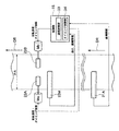
先ず、図1を参照して、本発明の実施の形態に係わるカラー複写機100の内部構成の概略について説明する。カラー複写機100は、原稿30に形成された色画像を読み取って画像情報を取得し、この画像情報に基づいて感光体ドラム上に各色の画像を形成した後、用紙上に色を重ね合わせた画像を形成する装置である。
First, with reference to FIG. 1, an outline of an internal configuration of a
カラー複写機100は、複写機本体101を有している。複写機本体101の上部には、画像入力部11及びADF40が配設されている。ここで、「ADF」は「自動原稿搬送装置」の略称である。ADF40は、ADFモード時に、一又は複数の原稿30を自動給紙するように動作する。ここに、「ADFモード」とは「自動給紙モード」の略称であって、ADF40に載置された原稿30を自動給紙して原稿画像を自動的に読み取る動作をいう。
The
ADF40は、原稿載置部41、ローラ42a、ローラ42b、ローラ43、搬送ローラ44及び排紙皿46を有している。原稿載置部41には一又は複数の原稿30が載置される。原稿載置部41の下流側にはローラ42a及びローラ42bが設けられている。ADFモードが選択されたとき、原稿載置部41から繰り出された原稿30は、下流側のローラ43によってU字回転するように搬送される。なお、ADFモードが選択された場合、原稿30の記録面は原稿載置部41で上に向けて載置される。
The ADF 40 includes a
また、画像入力部11は、原稿30に形成された色画像を読み取るように動作する。画像入力部11には、例えば、カラー用のスリットスキャン型のスキャナが使用される。画像入力部11にはアレイ状に配列されたイメージセンサ58が備えられ、例えば、ADFモード時に、原稿30がローラ43によってU字状に反転するときに、その原稿30の表面を読み取って画像読取信号Soutを出力するようになされる。イメージセンサ58には、例えば3ラインカラーCCDからなる撮像装置が使用される。ここで、「CCD」は「電荷結合素子」の略称である。
Further, the
イメージセンサ58は、複数の受光素子列が主走査方向に配置されて構成される赤色、緑色及び青色光検出用の3つの読み取りセンサを備え、3つの読み取りセンサは、主走査方向と直交する副走査方向の異なる位置で画素を分割して赤色、緑色及び青色の光情報を同時に読み取る。
The
画像入力部11で読み取られた原稿30は、搬送ローラ44により搬送されて排紙皿46へ排紙される。また、イメージセンサ58は、プラテンモード時に、原稿30を読み取って得たRGB色系の画像読取信号を出力するようになされる。ここに「プラテンモード」とは、プラテンガラス上に載置された原稿30に光学駆動系を走査して原稿画像を自動的に読み取る動作をいう。
The document 30 read by the
画像入力部11は、イメージセンサ58の他に、第1のプラテンガラス51、第2のプラテンガラス52、光源53、ミラー54、ミラー55、ミラー56、結像光学部57及び特に図示しない光学駆動部を有している。ここで第2のプラテンガラス52にはADFガラスが含まれる。光源53は、原稿30に光を照射する。光学駆動部は原稿30又はイメージセンサ58を副走査方向に相対的に移動するように動作する。副走査方向とは、イメージセンサ58を構成する複数の受光素子の配置方向を主走査方向としたとき、この主走査方向と直交する方向をいう。ミラー54〜56は、原稿30で反射された光を折り返すように配置され、結像光学部57は、折り返された光をイメージセンサ58上で結像させる。このように、ADF40の原稿載置部41に載置された原稿30は前述したローラ42a、42b、43及び搬送ローラ44により搬送され、光源53、ミラー54、55、56、結像光学部57及び光学駆動部を含む画像入力部11の光学系により原稿30の片面又は両面の画像が走査露光され、原稿30の画像情報を反映する反射光がイメージセンサ58により読み込まれる。
In addition to the
イメージセンサ58は、入射光の光量を電荷量に光電変換する。光電変換されたアナログの画像読取信号は画像入力部11内においてA/D変換されてデジタルの画像読取信号Soutが画像入力部11から出力される。画像入力部11には制御部15を介して画像処理部31が接続されている。画像処理部31はデジタルの画像読取信号Soutに対して画像圧縮処理及び変倍処理等を施して、赤色、緑色、青色成分各々の画像データへ変換する。更に、画像処理部31は、赤色、緑色、青色成分各々の画像データを3次元色情報変換テーブルによって、イエロー、マゼンダ、シアン、ブラック色用の画像データDy、Dm、Dc、Dkに変換する。変換された画像データDy、Dm、Dc、Dkは画像形成部60を構成する露光部3Y、3M、3C、3Kへそれぞれ転送される。
The
複写機本体101は、タンデム型のカラー画像形成装置と称せされるものである。複写機本体101には、画像形成部60が設けられている。画像形成部60は、画像入力部11により読み取って得た画像データDy、Dm、Dc、Dkに基づいて色画像を形成する。画像形成部60は、イエロー、マゼンダ、シアン、ブラックの色毎に感光ドラムを有する複数の画像形成ユニット10Y、10M、10C、10Kと、無終端状の中間転写体6と、中間転写体6から用紙に転写したトナー像を定着するための定着装置17とを備える。
The copying machine
イエロー色の画像を形成する画像形成ユニット10Yは、イエロー色のトナー像を形成する感光体ドラム1Yと、感光体ドラム1Yの周囲に配置されたイエロー色用の帯電部2Yと、露光部3Yと、現像部4Yと、像形成体用のクリーニング部8Yとを有する。マゼンダ色の画像を形成する画像形成ユニット10Mは、マゼンダ色のトナー像を形成する感光体ドラム1Mと、マゼンダ色用の帯電部2Mと、露光部3Mと、現像部4Mと、像形成体用のクリーニング部8Mとを有する。
The image forming unit 10Y that forms a yellow image includes a photosensitive drum 1Y that forms a yellow toner image, a yellow charging unit 2Y disposed around the photosensitive drum 1Y, and an
シアン色の画像を形成する画像形成ユニット10Cは、シアン色のトナー像を形成する感光体ドラム1Cと、シアン色用の帯電部2Cと、露光部3Cと、現像部4Cと、像形成体用のクリーニング部8Cとを有する。ブラック色の画像を形成する画像形成ユニット10Kは、ブラック色のトナー像を形成する感光体ドラム1Kと、ブラック色用の帯電部2Kと、露光部3Kと、現像部4Kと、像形成体用のクリーニング部8Kとを有する。
An
感光体ドラム1Y、1M、1C、1Kは、カラー画像が形成される用紙の搬送方向に垂直な所定の軸を中心にして回転する円柱体である。帯電部2Y、2M、2C及び2Kは、回転する感光体ドラム1Y、1M、1C、1Kの側面に対して連続して電荷を一様に供給することによって感光体ドラム1Y、1M、1C、1Kの側面を帯電させる。
The
露光部3Y、3M、3C、3Kは、上述した所定の軸に平行な主走査方向に沿って線状に配置された複数の光変調素子を備える。例えば、露光部3Y、3M、3C、3Kとして、光変調素子としてLED素子が用いられたLPHを使用することができる。「LPH」はLEDプリントヘッドの略称である。各光変調素子は感光体ドラム1Y、1M、1C、1Kの側面に対して光を照射する。露光部3Y、3M、3C及び3Kは、画像データDy、Dm、Dc、Dkに基づいて、回転する感光体ドラム1Y、1M、1C、1Kの側面に照射される光を変調する。このようにして、回転している感光体ドラム1Y、1M、1C、1Kの側面に対して所定の軸に平行な線状の光を断続的に照射することにより、各々の感光体ドラム1Y、1M、1C、1K上に静電潜像を形成する。これを「露光」という。
The
現像部4Y、4M、4C、4Kは、感光体ドラム1Y、1M、1C、1K上の静電潜像を現像して、イエロー色、マゼンダ色、シアン色、ブラック色のそれぞれのトナー像を形成する。これを「現像」という。現像部4Y、4M、4C、4Kによる現像は、使用するトナー極性と同極性である、例えば負極性の直流電圧に交流電圧を重畳した現像バイアスが印加される反転現像にて行われる。
The developing
中間転写体6は、複数のローラにより回転可能に支持されている。1次転写ローラ7Y、7M、7C、7Kは、中間転写体6を挟んで感光体ドラム1Y、1M、1C、1Kに対向する位置に設置されている。使用するトナーと反対極性である、例えば正極性の1次転写バイアスを1次転写ローラ7Y、7M、7C、7Kに印加することにより、各々の感光体ドラム1Y、1M、1C、1Kに形成されたイエロー色、マゼンダ色、シアン色、ブラック色のそれぞれのトナー像は、回転する中間転写体6上に重ね合わせて逐次転写される。このようにして、イエロー色、マゼンダ色、シアン色、ブラック色のそれぞれのトナー像を重ね合わされたカラートナー像を中間転写体6上に形成する。これを「1次転写」という。
The
また、画像形成部60の下方には、画像形成部60に用紙Pを搬送するように動作する搬送部20が設けられている。本発明の実施の形態に係わる用紙搬送装置は、この搬送部20に対して適用することができる。搬送部20は、用紙Pを収容する給紙トレイ20A、20B、20Cと、用紙Pを挟持して回転することにより一定の方向に用紙を搬送する複数のローラ対21、22A、22B、22C、22D、23、28を有している。給紙トレイ20A等に収容された用紙Pは、給紙トレイ20A等に設けられた送り出しローラ対21及び給紙ローラ対22Aにより給紙され、搬送ローラ対22B、22C、22D、23、レジストローラ対28等を経て、2次転写ローラ対7Aに搬送され、用紙P上の一方の面、例えば表面にカラートナー像が中間転写体6から用紙Pへ一括して転写される。これを「2次転写」という。
Further, below the
定着装置17は、カラートナー像が転写された用紙Pに熱及び圧力を加えてトナーを用紙P上に溶着させる。これを「定着処理」という。定着処理後の用紙Pは、排紙ローラ対24に挟持されて機外の排紙トレイ25上に載置される。転写後の感光体ドラム1Y、1M、1C、1Kの外周面上に残った転写残トナーは、クリーニング部8Y、8M、8C、8Kにより除去されて次のカラー画像を形成するサイクルに入る。
The fixing
用紙Pの両面に画像を形成する時には、表面に画像を形成した後、定着装置17から排出された用紙Pが分岐部26により排紙路から分岐される。次いで、用紙Pは、下方の循環通紙路27Aを経て、再給紙機構である反転搬送路27Bより表裏を反転され、再給紙搬送部27Cを通過して、搬送ローラ対22Dから前述した転写経路に合流する。
When forming images on both sides of the paper P, the paper P discharged from the fixing
反転搬送された用紙Pは、レジストローラ対28を経て、再度2次転写ローラ7Aに搬送され、用紙Pの裏面上にカラートナー像が一括転写される。一方、2次転写ローラ7Aにより用紙Pにカラートナー画像を転写した後、用紙Pを曲率分離した中間転写体6上に残された残留トナーは、中間転写体用のクリーニング部8Aにより除去される。
The reversely conveyed sheet P is conveyed again to the
図1には示さないが、カラー複写機100は、複写機本体101の他に、これに隣接して配置された後処理装置及び大容量給紙装置を備える。後処理装置は、大容量スタック、仕分け、ステイプル、パンチ穴空け、用紙折り、表紙挿入、簡易製本、断裁などを行い、大容量給紙部は、大量の給紙を行う。
Although not shown in FIG. 1, the
上記したように、搬送部20は、給紙トレイ20A、20B、20Cから2次転写ローラ対7Aまでの搬送路や、2次転写ローラ対7Aから分岐部26、循環通紙路27A、反転搬送路27B、再給紙搬送部27Cを通じて再び2次転写ローラ対7Aに戻る搬送路において、用紙Pを一定の方向に搬送する。ここで「一定の方向」は用紙Pの搬送方向に相当する。
As described above, the
搬送部20は、補正ローラ対23よりも上流側の搬送路上に配置された第1の検出部23Mと、第1の検出部23Mよりも上流側の搬送路上に配置された第2の検出部21A、21Bとを更に備える。第1の検出部23Mは、補正ローラ対23へ搬送される時の用紙Pの斜行及び片寄りを検出することを目的としているため、補正ローラ対23の上流に配置する。図1の例では、補正ローラ対23と搬送ローラ対22C、22Dの間に配置されている。
The
第2の検出部21A、21Bは、搬送路上において発生する用紙Pの片寄りを補正する時の目標位置を検出することを目的としているため、第1の検出部23Mより上流側に配置する。図1の例において、第2の検出部21Aは、送り出しローラ対21と給紙ローラ対22Aの間に配置され、第2の検出部21Bは、再給紙搬送部27Cの反転搬送路27B側に配置されている。なお、図1に示す第1の検出部23M及び第2の検出部21A、21Bの配置は一例に過ぎず、その他の場所に配置しても構わない。
Since the
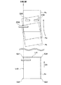
次に、用紙Pの斜行及び片寄りを補正する搬送部20の構成及び動作について説明する。図2に示すように、搬送部20は、図1の補正ローラ対23として、搬送方向DRに垂直な同軸上に配置された第1のローラ対23A及び第2のローラ対23Bを備える。第1のローラ対23Aにはモータなどからなる第1の駆動部Maが回転軸を介して接続され、第2のローラ対23Bにはモータなどからなる第2の駆動部Mbが回転軸を介して接続されている。第1の駆動部Maは、回転軸を介して第1のローラ対23Aに対して回転方向の動力を伝達して第1のローラ対23Aを回転させ、第2の駆動部Mbは回転軸を介して第2のローラ対23Bに対して回転方向の動力を伝達して第2のローラ対23Bを回転させる。このように、第1のローラ対23A及び第2のローラ対23Bは、それぞれ第1の駆動部Ma及び第2の駆動部Mbによって独立して駆動される。
Next, the configuration and operation of the
第1の検出部23M、第2の検出部21Aは、それぞれ、例えば、搬送方向DRに直交する方向に複数のイメージセンサが直線状に並べられたラインセンサを備える。ラインセンサは、用紙が通過する範囲PAの一方の端部を跨いでラインセンサの感度領域が形成されている。図2の例では、搬送方向に向かって左側の端部を跨いでラインセンサの感度領域が形成されている。
Each of the
第1の検出部23Mは、第1のローラ対23A及び第2のローラ対23Bへ到達する前に用紙の搬送方向DRに対する曲がり角度、及び用紙の搬送方向DRに垂直な方向の端部の位置を検出する。第2の検出部21Aは、第1の検出部23Mによって曲がり角度及び端部の位置が検出される以前に用紙の搬送方向DRに垂直な方向の端部の位置を検出する。図2の例において、第1の検出部23M及び第2の検出部21Aは、搬送方向DRに向かって左側の端部の位置を検出する。
The
制御部15は、第1の検出部23Mによって検出された曲がり角度に基づいて、第1のローラ対23A及び第2のローラ対23Bの回転速度を変更すると共に、第1の検出部23Mによって検出された用紙の端部の位置に基づいて、回転速度を変更するタイミングを制御する。制御部15は、第2の検出部21Aによって検出された用紙の端部の位置を目標位置にして速度制御部33が速度に差を付け始めるタイミングを制御する。
The
具体的に、制御部15は、第1の検出部23Mから曲がり角度及び端部の位置を示すデータ信号を受信して、第1の駆動部Ma及び第2の駆動部Mbの回転速度を変更する。これにより、制御部15は、第1の検出部23Mによって検出された用紙の斜行を補正することができる。ここで、「斜行」は、用紙が搬送方向DRに対して斜めに進むことをいう。
Specifically, the
制御部15は、第2の検出部21Aから用紙の端部の位置を示すデータ信号、及び第1の検出部23Mから曲がり角度及び端部の位置を示すデータ信号を受信して、第1の駆動部Ma及び第2の駆動部Mbの回転速度を変更するタイミングを制御する。これにより、制御部15は、第1の検出部23Mによって検出された用紙の片寄りを補正することができる。ここで、「片寄り」とは、用紙の搬送方向DRに垂直な方向の位置が所定の目標位置からずれていることをいう。
The
なお、図2では、第2の検出部21Aについて説明したが、第2の検出部21Bも第2の検出部21Aと同様な構成及び機能を備ええる。
Although the
図3及び図4を参照して、図2に示した搬送部20が搬送路上において発生する用紙の斜行及び片寄りを補正する手順を説明する。
With reference to FIG. 3 and FIG. 4, a description will be given of a procedure in which the
(イ)先ずS01段階において、用紙が第2の検出部21Aに到達することを待機する。用紙が第2の検出部21Aに到達した場合(S01でYES)、S03段階に進み、第2の検出部21Aが、用紙の搬送方向DRに垂直な方向の端部の位置を検出する。具体的に、第2の検出部21Aは、図4に示すように、図示しない給紙トレイ20A、20B、20Cから給紙された用紙PFの搬送方向DRに垂直な方向の角部Ed1の位置を検出し、検出された角部Ed1の位置のデータ信号を制御部15へ送信する。
(A) First, in step S01, the process waits for the sheet to reach the
(ロ)S05段階に進み、この用紙が第1の検出部23Mに到達することを待機する。用紙が第1の検出部23Mに到達した場合(S05でYES)、S07段階に進み、第1の検出部23Mが、用紙の搬送方向DRに対する曲がり角度、及び用紙の搬送方向DRに垂直な方向の端部の位置を検出する。具体的に、第1の検出部23Mは、図4に示すように、第1のローラ対23A及び第2のローラ対23Bによって搬送される前の用紙PBの搬送方向DRに対する曲がり角度、及び用紙PBの搬送方向DRに垂直な方向の角部Ed1の位置を検出し、検出された曲がり角度及び角部Ed1の位置のデータ信号を制御部15へ送信する。
(B) Proceed to step S05 and wait for this sheet to reach the
(ハ)S09段階に進み、制御部15は、第1の検出部23Mによって検出された曲がり角度に基づいて、第1のローラ対23Aと第2のローラ対23Bの回転速度の差を算出する。そして、制御部15は、第2の検出部21Aによって検出された用紙PFの角部Ed1の位置、第1の検出部23Mによって検出された用紙PBの角部Ed1の位置、及び算出された回転速度の差に基づいて、回転速度を変更するタイミングを算出する。
(C) Proceeding to step S09, the
(ニ)S11段階に進み、制御部15は、算出した回転速度の差にしたがって、第1の駆動部Ma及び第2の駆動部Mbの回転速度に差を付ける。同時に、制御部15は、算出した制御開始タイミングにしたがって、前記回転速度を変更するタイミングを制御する。具体的に、制御部15は、図4に示すように、算出した制御開始タイミングが到来した用紙PMに対して、算出した回転速度の差に従って、第1のローラ対23A及び第2のローラ対23Bの回転速度を変更する。
(D) Proceeding to step S11, the
(ホ)図4の例では、用紙PBが半時計回りの方向へ斜行しているため、第1のローラ対23Aの回転速度を第2のローラ対23Bの回転速度よりも速くするか、第2のローラ対23Bの回転速度を第1のローラ対23Aの回転速度よりも遅くする。これにより、用紙PMは時計回りの方向に回転し始める。制御部15は、この速度差の制御を、図4の用紙PAに示す状態、すなわち、第1の検出部23Mによって検出された用紙の斜行及び片寄りを補正された状態まで継続し、補正後は第1のローラ対23A及び第2のローラ対23Bを同じ回転速度に変更して回転させる。このように、この速度差の制御を開始するタイミングを制御することによって、第1の検出部23Mによって検出された用紙の斜行及び片寄りを同時に補正することができる。
Or in the example of (e) 4, since the sheet P B is skewed to the counterclockwise direction, faster than the rotational speed of the rotational speed of the first pair of
(へ)最後に、S13段階に進み、制御部15は、カラー複写機100が受け付けたジョブが終了したか否かを判断する。ジョブが終了していない場合(S13でNO)、S01段階に戻り、上述した手順を繰り返し実施する。そして、ジョブが終了した場合(S13でYES)、図3に示すフローチャートは終了する。
(F) Finally, proceeding to step S13, the
次に、図5(a)及び図5(b)を参照して、第1の検出部23Mによって検出された用紙PMの片寄り量△Aと速度差の制御を開始するタイミングとの関係を説明する。図5(a)に示すように、用紙PMの片寄り量△Aが比較的小さい場合は、用紙PMの前方位置を第1のローラ対23A及び第2のローラ対23Bが挟んでいる時に速度差の制御を開始する。一方、図5(b)に示すように、用紙PMの片寄り量△Aが比較的大きい場合は、用紙PMの後方位置を第1のローラ対23A及び第2のローラ対23Bが挟んでいる時に速度差の制御を開始する。なお、図5(a)及び図5(b)において用紙PMの曲がり角度は同じである。ここで、図5の「目標位置」は第2の検出部21Aによって検出された用紙PFの角部Ed1の位置に相当する。また、用紙PMの「片寄り量△A」とは、目標位置から第1の検出部23Mによって検出された用紙PBの角部Ed1までの搬送方向DRに垂直な方向の距離である。
Next, with reference to FIGS. 5 (a) and 5 (b), the first detector relationship between the timing for starting the control of the amount of the bias △ A and the speed difference between the detected sheet P M by 23M Will be explained. As shown in FIG. 5 (a), the deviation amount △ A of the sheet P M can be relatively small, which sandwich the forward position of the sheet P M is the first pair of
速度差の制御による用紙PMの回転移動は、第1のローラ対23A及び第2のローラ対23Bの軸上或いはその近傍を、回転中心として行われる。よって、用紙PMの回転角度が同じであっても、図5(a)に示すように速度差の制御を開始するタイミングが早ければ用紙PMの角部Ed1の移動距離は短く、図5(b)に示すように速度差の制御を開始するタイミングが遅ければ用紙PMの角部Ed1の移動距離は長くなる。そこで、用紙PMの片寄り量△Aに応じて速度差の制御を開始するタイミングを制御することにより、用紙PMの斜行を補正すると同時に用紙PMの片寄りも補正することが可能となる。
Rotational movement of the sheet P M by the control of the speed difference, the on-axis or near the first pair of
図6(a)〜図6(c)を参照して、第1の検出部23Mによって検出された用紙の片寄り量△Aと曲がり角度θの様々な組み合わせについて説明する。
With reference to FIG. 6A to FIG. 6C, various combinations of the paper deviation amount ΔA detected by the
図6(a)の<基準>は、第1の検出部23Mによって基準片寄り量△Ab及び基準曲がり角度θbが検出された場合を示す。この場合において目標位置にくる用紙の辺Ln2上の点を基準紙端位置Gbとする。
<Reference> in FIG. 6A shows a case where the reference deviation amount ΔAb and the reference bending angle θb are detected by the
図6(a)の<パターン1>は、第1の検出部23Mによって検出された片寄り量△Aが基準片寄り量△Abよりも大きく、且つ曲がり角度θが基準曲がり角度θbと等しい場合を示す。この場合において目標位置にくる用紙の辺Ln2上の点は基準紙端位置Gbよりも後方に位置する。以後、目標位置にくる用紙の辺Ln2上の点を紙端位置Gという。図6(a)の<パターン2>は、第1の検出部23Mによって検出された片寄り量△Aが基準片寄り量△Abよりも小さく、且つ曲がり角度θが基準曲がり角度θbと等しい場合を示す。この場合における紙端位置Gは基準紙端位置Gbよりも前方に位置する。
In <
図6(b)の<パターン3>は、第1の検出部23Mによって検出された片寄り量△Aが基準片寄り量△Abに等しく、且つ曲がり角度θが基準曲がり角度θbよりも大きい場合を示す。この場合における紙端位置Gは基準紙端位置Gbよりも前方に位置する。図6(b)の<パターン4>は、第1の検出部23Mによって検出された片寄り量△Aが基準片寄り量△Abに等しく、且つ曲がり角度θが基準曲がり角度θbよりも小さい場合を示す。この場合における紙端位置Gは基準紙端位置Gbよりも後方に位置する。
<
図6(c)の<パターン5>は、第1の検出部23Mによって検出された片寄り量△Aが基準片寄り量△Abよりも大きく、且つ曲がり角度θが基準曲がり角度θbよりも大きい場合を示す。この場合における紙端位置Gと基準紙端位置Gbの位置関係は一義的に定まらず、検出された片寄り量△Aと曲がり角度θの関係に応じて変化する。図6(c)の<パターン6>は、第1の検出部23Mによって検出された片寄り量△Aが基準片寄り量△Abよりも小さく、且つ曲がり角度θが基準曲がり角度θbよりも小さい場合を示す。この場合における紙端位置Gと基準紙端位置Gbの位置関係も一義的に定まらず、検出された片寄り量△Aと曲がり角度θの関係に応じて変化する。
In <
図6(a)の<パターン2>及び図6(b)の<パターン3>では、紙端位置Gは基準紙端位置Gbよりも前方に位置するので、図5(a)に示したように速度差の制御を開始するタイミングを早くして用紙PMの角部Ed1の移動距離を短くする。また、図6(a)の<パターン3>における速度差は<基準>における速度差よりも大きくする。
In <
図6(c)の<パターン5>及び<パターン6>では、紙端位置Gと基準紙端位置Gbの位置関係が一義的に定まらないので、速度差の制御を開始するタイミングについても、検出された片寄り量△A及び曲がり角度θに応じて変化する。
In <
なお、図6には示さないパターンとして、第1の検出部23Mによって検出された片寄り量△Aが基準片寄り量△Abよりも小さく、且つ曲がり角度θが基準曲がり角度θbよりも大きい場合と、第1の検出部23Mによって検出された片寄り量△Aが基準片寄り量△Abよりも大きく、且つ曲がり角度θが基準曲がり角度θbよりも小さい場合とがある。前者の場合、紙端位置Gは基準紙端位置Gbよりも前方に位置するので、図5(a)に示したように速度差の制御を開始するタイミングを早くして用紙PMの角部Ed1の移動距離を短くする。後者の場合、紙端位置Gは基準紙端位置Gbよりも後方に位置するので、図5(b)に示したように速度差の制御を開始するタイミングを遅くして用紙PMの角部Ed1の移動距離を長くする。
As a pattern not shown in FIG. 6, when the deviation amount ΔA detected by the
このように、紙端位置Gが基準紙端位置Gbよりも前方に位置するか後方に位置するかに応じて、速度差の制御を開始するタイミングを基準のタイミングよりも早くするか或いは遅くするかを決めることができる。 As described above, the timing for starting the control of the speed difference is made earlier or later than the reference timing depending on whether the paper edge position G is located in front of or behind the reference paper edge position Gb. Can decide.
図7の表に、図6に示す様々な片寄り量△Aと曲がり角度θの組み合わせにおける速度差の制御を開始するタイミングとの関係を具体的な数値を用いてまとめた。図7において、「片寄り量(mm)」は、図6の基準位置に対する片寄り量を、目標位置から遠ざかる方向を正として示す。「曲がり角度(度)」は、図6の基準曲がり角度θbに対する曲がり角度を示す。「速度変更タイミング(msec)」は、基準時間に対するローラ23Aとローラ23Bの回転速度を変更するタイミングを示す。「パターン」は、図6のパターン番号を示す。図7の例では、片寄り量△Abを1mmとし、基準曲がり角度θbを5度とし、制御タイミングの基準時間を212msecに設定した場合を示す。ここで、制御タイミングの基準時間とは、用紙の先端から用紙の中央がループローラに到達するまでの時間を示す。
The table of FIG. 7 summarizes the relationship between the timing of starting the control of the speed difference in the combination of the various deviation amounts ΔA and the bending angle θ shown in FIG. 6 using specific numerical values. In FIG. 7, “deviation amount (mm)” indicates the deviation amount with respect to the reference position in FIG. 6 with the direction away from the target position being positive. “Bending angle (degree)” indicates a bending angle with respect to the reference bending angle θb in FIG. 6. “Speed change timing (msec)” indicates a timing for changing the rotation speed of the
図7に示すように、図6(a)の<パターン1>の一例として、片寄り量が+0.5、曲がり角度が0の場合、速度変更タイミングは+7となる。図6(a)の<パターン2>の一例として、片寄り量が−0.5、曲がり角度が0の場合、速度変更タイミングは−8となる。
As shown in FIG. 7, as an example of <
また、図6(b)の<パターン3>の一例として、片寄り量が0、曲がり角度が+1の場合、速度変更タイミングは+9となる。図6(b)の<パターン4>の一例として、片寄り量が0、曲がり角度が−1の場合、速度変更タイミングは−15となる。
Further, as an example of <
また、図6(c)の<パターン5>の一例として、片寄り量が+0.5、曲がり角度が+1の場合、速度変更タイミングは+24となる。図6(c)の<パターン6>の一例として、片寄り量が−0.5、曲がり角度が−1の場合、速度変更タイミングは−10となる。
As an example of <
次に、図8を参照して、制御部15が、第1のローラ対23Aの速度V1及び第2のローラ対23Bの速度V2、及び速度差の制御を開始するタイミングTを算出する方法の一例を説明する。ここでは、用紙が反時計回りの方向に斜行し、第2のローラ対23Bの中心を回転の中心とした場合について説明する。
Next, referring to FIG. 8, the
第1のローラ対23Aと第2のローラ対23Bの速度差△V=V1−V2は、第2のローラ対23Bの中心と第1のローラ対23Aの中心を結ぶ線分を第1のローラ対23A側の一端を中心にして時計方向に角度θだけ回転させたときの線分の他端の移動距離に相当する。角度θは、第1の検出部23Mによって検出された曲がり角度θである。
The speed difference ΔV = V1−V2 between the
回転移動前の用紙PBの角部Ed1の座標を(X,Y)=(A,B)とすると、回転移動後の用紙PAの角部Ed1の座標(A’,B’)は、(1)式及び(2)式で求められる。ここで、距離Rは、用紙の回転中心である第2のローラ対23Bの中心と角部Ed1との距離であって、速度V1、V2及びタイミングTの関数である。
The coordinates of the corner part Ed1 of the sheet P B before the rotation movement (X, Y) = (A , B) and when the coordinates of the corner part Ed1 of the sheet P A after the rotation movement (A ', B') is, It is obtained by the formulas (1) and (2). Here, the distance R is the distance between the center of the
A’=R(Acosθ−Bsinθ) ・・・・・(1)
B’=R(Bcosθ+Asinθ) ・・・・・(2)
R=F(V1、V2、T)
第1の検出部23Mによって検出された片寄り量△Aは(3)式で求められる。
A ′ = R (A cos θ−B sin θ) (1)
B ′ = R (B cos θ + Asin θ) (2)
R = F (V1, V2, T)
The deviation amount ΔA detected by the
△A=A’−A
=F(V1、V2、T)×((Acosθ−1)−Bsinθ) ・・・(3)
F(V1、V2、T)は、テーブル、方程式、実験値のいずれかによって決定することによって、制御部15は、第1のローラ対23Aの速度V1及び第2のローラ対23Bの速度V2、及び速度差の制御を開始するタイミングTを算出する。
ΔA = A'-A
= F (V1, V2, T) × ((A cos θ−1) −B sin θ) (3)
F (V1, V2, T) is determined by any one of a table, an equation, and an experimental value, so that the
以上説明したように、本発明の実施の形態によれば、以下の作用効果が得られる。 As described above, according to the embodiment of the present invention, the following effects can be obtained.
第1の駆動部Ma及び第2の駆動部Mbは第1のローラ対23A及び第2のローラ対23Bをそれぞれ独立して駆動するので、制御部15は第1のローラ対23A及び第2のローラ対23Bの回転速度を個別に制御することができる。第1のローラ対23A及び第2のローラ対23Bが用紙Pを挟持している間に回転速度に差を付けることにより、第1のローラ対23A及び第2のローラ対23Bは用紙Pを搬送すると同時に用紙Pの向きを変化させることができる。そこで、制御部15は、第1の検出部23Mによって検出された用紙Pの曲がり角度に基づいて第1のローラ対23A及び第2のローラ対23Bが回転する速度に差を付けることにより、用紙Pの向きを所定の基準の向きへ調整することができる。
Since the first drive unit Ma and the second drive unit Mb drive the
また、制御部15による回転速度を変更するタイミングが比較的早ければ、用紙Pの後部が搬送方向DRに垂直な方向に大きく変位する。一方、制御部15による回転速度を変更するタイミングが比較的遅ければ、用紙Pの前部が搬送方向DRに垂直な方向に大きく変位する。そこで、制御部15は、第1の検出部23Mによって検出された用紙Pの角部Ed1の位置に基づいて、回転速度を変更するタイミングを制御することにより、用紙Pの角部Ed1の位置を所定の目標位置へ調整することができる。
If the timing for changing the rotation speed by the
更に、第1の駆動部Ma及び第2の駆動部Mbが第1のローラ対23A及び第2のローラ対23Bをそれぞれ独立して駆動する機構を備えていればよいので、比較的単純な機構によって用紙Pの向き及び用紙Pの端部の位置を調整することができる。
Furthermore, since the first drive unit Ma and the second drive unit Mb only need to have a mechanism for independently driving the
したがって、本発明の実施の形態によれば、単純な機構によって用紙Pの斜行と片寄りを補正可能な搬送部20を備えるカラー複写機100を提供することができる。
Therefore, according to the embodiment of the present invention, it is possible to provide the
第2の検出部21Aは、第1の検出部23Mによって曲がり角度及び角部Ed1の位置が検出される前の用紙Pの搬送方向DRに垂直な方向の角部Ed1の位置を検出し、制御部15は、第2の検出部21Aによって検出された角部Ed1の位置を目標位置にして回転速度を変更するタイミングを制御する。これにより、制御部15は、用紙Pの角部Ed1の位置を第2の検出部21Aによって検出された用紙Pの角部Ed1の位置へ調整することができるので、用紙Pの片寄りを補正する際の目標位置を用紙Pごとに設定することが可能となる。
The
上記のように、本発明は、1つの実施形態によって記載したが、この開示の一部をなす論述及び図面はこの発明を限定するものであると理解すべきではない。この開示から当業者には様々な代替実施の形態、実施例及び運用技術が明らかとなろう。 As described above, the present invention has been described by way of one embodiment, but it should not be understood that the discussion and drawings that form part of this disclosure limit the present invention. From this disclosure, various alternative embodiments, examples and operational techniques will be apparent to those skilled in the art.
例えば、実施の形態では、第1の検出部23M及び第2の検出部21Aのそれぞれが検出する用紙Pの搬送方向DRに垂直な方向の端部の位置として、用紙Pの角部Ed1の位置を例示して説明したが、端部はこれに限定されるものではない。その他の角部Ed2〜Ed4や、角部Ed1と角部Ed4を結ぶ用紙Pの辺Ln2や、角部Ed2と角部Ed3を結ぶ用紙Pの辺の位置であっても構わない。
For example, in the embodiment, the position of the corner portion Ed1 of the sheet P as the position of the end in the direction perpendicular to the transport direction DR of the sheet P detected by the
また、第2の検出部21Aとして説明したが本発明はこれに限らない。用紙Pの裏面に画像を形成する際には、第2の検出部21Aの代わりに第2の検出部21Bを用いて用紙Pの片寄りを補正すればよい。
Moreover, although demonstrated as the
実施の形態においては、制御部15が第2の検出部21Aによって検出された用紙Pの端部の位置を目標位置にして回転速度を変更するタイミングを制御する場合について説明したが、本発明はこれに限定されない。例えば、制御部15は、予め定めた位置を目標位置にして回転速度を変更するタイミングを制御しても構わない。この場合、搬送部20の構成としては、第2の検出部21A、21Bが不要となる。これにより、制御部15は、用紙Pの端部の位置を予め定めた目標位置へ調整することができるので、片寄りを補正した後の用紙Pの端部の位置を画一化することが可能となる。
In the embodiment, the case has been described in which the
また、本発明の実施の形態では、給紙トレイから定着装置へ用紙Pを搬送する搬送部20に対して本発明の用紙搬送装置を適用した場合について説明したが、カラー複写機100の原稿30を搬送するADF40に対しても適用することは可能である。本発明の用紙搬送装置は、用紙Pや原稿30などを含む用紙を搬送する機構に対して適用することができる。
In the embodiment of the present invention, the case where the paper transport device of the present invention is applied to the
また、本発明の実施の形態においては、用紙搬送装置を備えるカラー複写機100について説明したが、カラー複写機100のみならず、モノクロ複写機、プリンタ、ファクシミリなど、用紙上に画像を形成する装置や原稿に記載された画像を読取る装置において、本発明の実施の形態に係わる用紙搬送装置を適用することができる。
Further, in the embodiment of the present invention, the
このように、本発明はここでは記載していない様々な実施の形態等を包含するということを理解すべきである。したがって、本発明はこの開示から妥当な特許請求の範囲に係る発明特定事項によってのみ限定されるものである。 Thus, it should be understood that the present invention includes various embodiments and the like not described herein. Therefore, the present invention is limited only by the invention specifying matters according to the scope of claims reasonable from this disclosure.
1C、1K、1M、1Y…感光体ドラム
2C、2K、2M、2Y…帯電部
3C、3K、3M、3Y…露光部
4C、4K、4M、4Y…現像部
6…中間転写体
7A…2次転写ローラ
7C、7K、7M、7Y…1次転写ローラ
8A、8C、8K、8M、8Y…クリーニング部
10C、10K、10M、10Y…画像形成ユニット
11…画像入力部
15…制御部
17…定着装置
20…搬送部
20A…給紙トレイ
21…ローラ対
21A、21B…第2の検出部
22A…給紙ローラ対
22B〜22D…搬送ローラ対
23…レジストローラ対
23A…第1のローラ対
23B…第2のローラ対
23M…第1の検出部
24…排紙ローラ
25…排紙トレイ
26…分岐部
27A…循環通紙路
27B…反転搬送路
27C…再給紙搬送部
30…原稿
31…画像処理部
40…ADF
41…原稿載置部
42a、42b、43…ローラ
44…搬送ローラ
46…排紙皿
51…第1のプラテンガラス
52…第2のプラテンガラス
53…光源
54〜56…ミラー
57…結像光学部
58…イメージセンサ
60…画像形成部
100…カラー複写機
101…複写機本体
Ed1〜Ed4…角部(端部)
DR…搬送方向(一定の方向)
Ma…第1の駆動部
Mb…第2の駆動部
P…用紙
θ…曲がり角度
△A…片寄り量
1C, 1K, 1M, 1Y ...
DESCRIPTION OF
DR: Transport direction (constant direction)
Ma: First driving unit Mb: Second driving unit P: Paper θ: Bending angle ΔA: Deviation amount
Claims (6)
前記第1のローラ対を駆動する第1の駆動部と、
前記第2のローラ対を駆動する第2の駆動部と、
前記第1のローラ対及び前記第2のローラ対へ到着する以前に搬送される前記用紙の前記一定の方向に対する曲がり角度、及び当該用紙の前記一定の方向に垂直な方向の端部の位置を検出する第1の検出部と、
前記第1の検出部によって検出された前記曲がり角度に基づいて、前記第1のローラ対及び前記第2のローラ対の回転速度を変更すると共に
前記第1の検出部によって検出された前記端部の位置に基づいて、前記第1のローラ対及び前記第2のローラ対を異なる回転速度に変更するタイミングを制御する制御部と
を備えることを特徴とする用紙搬送装置。 A first roller pair and a second roller pair that are arranged on the same axis perpendicular to a certain direction and convey the sheet in the certain direction by sandwiching and rotating the sheet;
A first drive unit for driving the first roller pair;
A second drive unit for driving the second roller pair;
A bending angle of the paper transported before arrival at the first roller pair and the second roller pair with respect to the certain direction, and a position of an end of the paper in a direction perpendicular to the certain direction. A first detector for detecting;
Based on the bending angle detected by the first detection unit, the rotational speed of the first roller pair and the second roller pair is changed, and the end portion detected by the first detection unit And a controller that controls the timing of changing the first roller pair and the second roller pair to different rotational speeds based on the positions of the sheet conveying device.
前記制御部は、前記第2の検出部によって検出された前記端部の位置を目標位置にして前記第1のローラ対及び第2のローラ対の回転速度を変更するタイミングを制御する
ことを特徴とする請求項1に記載の用紙搬送装置。 Before detecting the bending angle and the position of the end by the first detection unit, further comprising a second detection unit for detecting the position of the end of the sheet in a direction perpendicular to the certain direction,
The control unit controls the timing of changing the rotation speeds of the first roller pair and the second roller pair with the position of the end detected by the second detection unit as a target position. The sheet conveying apparatus according to claim 1.
用紙を搬送する用紙搬送装置を備える画像形成装置において、
前記用紙搬送装置は、
一定の方向に垂直な同軸上に配置され、且つ用紙を挟んで回転することにより前記一定の方向に前記用紙を搬送する第1のローラ対及び第2のローラ対と、
前記第1のローラ対を駆動する第1の駆動部と、
前記第2のローラ対を駆動する第2の駆動部と、
前記第1のローラ対及び前記第2のローラ対によって搬送される前の前記用紙の前記一定の方向に対する曲がり角度、及び当該用紙の前記一定の方向に垂直な方向の端部の位置を検出する第1の検出部と、
前記第1の検出部によって検出された前記曲がり角度に基づいて、前記第1のローラ対及び前記第2のローラ対の回転速度を変更すると共に
前記第1の検出部によって検出された前記端部の位置に基づいて、前記第1のローラ対及び前記第2のローラ対を異なる回転速度に変更するタイミングを制御する制御部と
を備えることを特徴とする画像形成装置。 An image forming unit for forming an image on paper;
In an image forming apparatus including a paper transport device that transports paper,
The paper conveying device is
A first roller pair and a second roller pair which are arranged on the same axis perpendicular to a certain direction and which convey the sheet in the certain direction by rotating with the sheet interposed therebetween;
A first drive unit for driving the first roller pair;
A second drive unit for driving the second roller pair;
A bending angle of the sheet before being conveyed by the first roller pair and the second roller pair with respect to the certain direction, and a position of an end portion of the sheet in a direction perpendicular to the certain direction are detected. A first detection unit;
Based on the bending angle detected by the first detection unit, the rotational speed of the first roller pair and the second roller pair is changed, and the end portion detected by the first detection unit An image forming apparatus comprising: a control unit that controls timing of changing the first roller pair and the second roller pair to different rotational speeds based on the positions of the first roller pair and the second roller pair.
前記制御部は、前記第2の検出部によって検出された前記端部の位置を目標位置にして前記第1のローラ対及び第2のローラ対の回転速度を変更するタイミングを制御する
ことを特徴とする請求項4に記載の画像形成装置。 Before detecting the bending angle and the position of the end by the first detection unit, further comprising a second detection unit for detecting the position of the end of the sheet in a direction perpendicular to the certain direction,
The control unit controls the timing of changing the rotation speeds of the first roller pair and the second roller pair with the position of the end detected by the second detection unit as a target position. The image forming apparatus according to claim 4.
Priority Applications (4)
| Application Number | Priority Date | Filing Date | Title |
|---|---|---|---|
| JP2008231098A JP5163378B2 (en) | 2008-09-09 | 2008-09-09 | Paper conveying apparatus and image forming apparatus |
| EP09168826A EP2161230A2 (en) | 2008-09-09 | 2009-08-27 | Sheet conveying apparatus and image forming apparatus |
| US12/551,743 US20100061783A1 (en) | 2008-09-09 | 2009-09-01 | Sheet conveying apparatus and image forming apparatus |
| CN2009101720583A CN101670950B (en) | 2008-09-09 | 2009-09-03 | Sheet conveying apparatus and image forming apparatus |
Applications Claiming Priority (1)
| Application Number | Priority Date | Filing Date | Title |
|---|---|---|---|
| JP2008231098A JP5163378B2 (en) | 2008-09-09 | 2008-09-09 | Paper conveying apparatus and image forming apparatus |
Publications (2)
| Publication Number | Publication Date |
|---|---|
| JP2010064820A true JP2010064820A (en) | 2010-03-25 |
| JP5163378B2 JP5163378B2 (en) | 2013-03-13 |
Family
ID=41404041
Family Applications (1)
| Application Number | Title | Priority Date | Filing Date |
|---|---|---|---|
| JP2008231098A Active JP5163378B2 (en) | 2008-09-09 | 2008-09-09 | Paper conveying apparatus and image forming apparatus |
Country Status (4)
| Country | Link |
|---|---|
| US (1) | US20100061783A1 (en) |
| EP (1) | EP2161230A2 (en) |
| JP (1) | JP5163378B2 (en) |
| CN (1) | CN101670950B (en) |
Cited By (4)
| Publication number | Priority date | Publication date | Assignee | Title |
|---|---|---|---|---|
| JP2012171782A (en) * | 2011-02-24 | 2012-09-10 | Konica Minolta Business Technologies Inc | Sheet reversing device, image forming apparatus, and sheet reversing method |
| CN103303649A (en) * | 2013-06-18 | 2013-09-18 | 宁波大鸿盛自动化设备有限公司 | Automatic differential correction device |
| US9731923B2 (en) | 2014-09-04 | 2017-08-15 | Seiko Epson Corporation | Medium transport method, medium transport device, and image recording device |
| JP2018087079A (en) * | 2016-11-30 | 2018-06-07 | コニカミノルタ株式会社 | Image formation device |
Families Citing this family (5)
| Publication number | Priority date | Publication date | Assignee | Title |
|---|---|---|---|---|
| JP5025435B2 (en) * | 2007-11-28 | 2012-09-12 | キヤノン株式会社 | Sheet conveying apparatus, image forming apparatus, and image reading apparatus |
| US9860403B2 (en) * | 2015-06-10 | 2018-01-02 | Canon Kabushiki Kaisha | Sheet feeding apparatus, and reading apparatus and image forming apparatus using the same |
| JP6546475B2 (en) * | 2015-08-12 | 2019-07-17 | キヤノン株式会社 | Image forming device |
| US9834399B1 (en) * | 2017-01-18 | 2017-12-05 | Kabushiki Kaisha Toshiba | Sheet processing system and control method |
| EP3896019B1 (en) * | 2020-04-16 | 2022-11-23 | Canon Production Printing Holding B.V. | Sheet transport system |
Citations (5)
| Publication number | Priority date | Publication date | Assignee | Title |
|---|---|---|---|---|
| JPH0412951A (en) * | 1990-05-02 | 1992-01-17 | Olympus Optical Co Ltd | Image forming device |
| JP2000302293A (en) * | 1999-04-15 | 2000-10-31 | Toshiba Corp | Sheet carrier, printing processor using sheet carrier, sheet carrying method and printing processing method |
| JP2006312512A (en) * | 2005-05-06 | 2006-11-16 | Canon Inc | Sheet skew correcting carrying device and image forming device |
| JP2008037581A (en) * | 2006-08-07 | 2008-02-21 | Canon Inc | Sheet conveying device, sheet conveying method, and image forming device |
| JP2009023830A (en) * | 2007-07-24 | 2009-02-05 | Canon Inc | Image processor |
Family Cites Families (12)
| Publication number | Priority date | Publication date | Assignee | Title |
|---|---|---|---|---|
| US4971304A (en) * | 1986-12-10 | 1990-11-20 | Xerox Corporation | Apparatus and method for combined deskewing and side registering |
| JPH05338859A (en) | 1992-06-11 | 1993-12-21 | Fuji Xerox Co Ltd | Device for correcting skew of paper sheet |
| US5725211A (en) * | 1995-08-28 | 1998-03-10 | Xerox Corporation | Method and apparatus for registering images on the front and the back of a single sheet of paper |
| US5678159A (en) * | 1996-06-26 | 1997-10-14 | Xerox Corporation | Sheet registration and deskewing device |
| US5887996A (en) * | 1998-01-08 | 1999-03-30 | Xerox Corporation | Apparatus and method for sheet registration using a single sensor |
| JP2002060097A (en) * | 2000-08-21 | 2002-02-26 | Fuji Xerox Co Ltd | Sheet conveying equipment |
| JP2002284399A (en) | 2001-03-22 | 2002-10-03 | Canon Inc | Sheet skew correcting and carrying device, and image forming device and image reading device with the same |
| JP4580602B2 (en) * | 2001-09-21 | 2010-11-17 | 株式会社東芝 | Paper sheet processing equipment |
| JP2003146484A (en) * | 2001-11-08 | 2003-05-21 | Canon Electronics Inc | Sheet carrier |
| JP4715578B2 (en) | 2005-06-17 | 2011-07-06 | コニカミノルタビジネステクノロジーズ株式会社 | Image forming apparatus |
| JP4739127B2 (en) * | 2006-06-22 | 2011-08-03 | キヤノン株式会社 | Sheet conveying apparatus, image forming apparatus, and image reading apparatus |
| JP4717900B2 (en) | 2007-02-20 | 2011-07-06 | 株式会社 資生堂 | Hair shape adjustment composition |
-
2008
- 2008-09-09 JP JP2008231098A patent/JP5163378B2/en active Active
-
2009
- 2009-08-27 EP EP09168826A patent/EP2161230A2/en not_active Withdrawn
- 2009-09-01 US US12/551,743 patent/US20100061783A1/en not_active Abandoned
- 2009-09-03 CN CN2009101720583A patent/CN101670950B/en active Active
Patent Citations (5)
| Publication number | Priority date | Publication date | Assignee | Title |
|---|---|---|---|---|
| JPH0412951A (en) * | 1990-05-02 | 1992-01-17 | Olympus Optical Co Ltd | Image forming device |
| JP2000302293A (en) * | 1999-04-15 | 2000-10-31 | Toshiba Corp | Sheet carrier, printing processor using sheet carrier, sheet carrying method and printing processing method |
| JP2006312512A (en) * | 2005-05-06 | 2006-11-16 | Canon Inc | Sheet skew correcting carrying device and image forming device |
| JP2008037581A (en) * | 2006-08-07 | 2008-02-21 | Canon Inc | Sheet conveying device, sheet conveying method, and image forming device |
| JP2009023830A (en) * | 2007-07-24 | 2009-02-05 | Canon Inc | Image processor |
Cited By (5)
| Publication number | Priority date | Publication date | Assignee | Title |
|---|---|---|---|---|
| JP2012171782A (en) * | 2011-02-24 | 2012-09-10 | Konica Minolta Business Technologies Inc | Sheet reversing device, image forming apparatus, and sheet reversing method |
| US8480079B2 (en) | 2011-02-24 | 2013-07-09 | Konica Minolta Business Technologies, Inc. | Sheet reversing apparatus, image forming apparatus and sheet reversing method |
| CN103303649A (en) * | 2013-06-18 | 2013-09-18 | 宁波大鸿盛自动化设备有限公司 | Automatic differential correction device |
| US9731923B2 (en) | 2014-09-04 | 2017-08-15 | Seiko Epson Corporation | Medium transport method, medium transport device, and image recording device |
| JP2018087079A (en) * | 2016-11-30 | 2018-06-07 | コニカミノルタ株式会社 | Image formation device |
Also Published As
| Publication number | Publication date |
|---|---|
| EP2161230A2 (en) | 2010-03-10 |
| CN101670950A (en) | 2010-03-17 |
| JP5163378B2 (en) | 2013-03-13 |
| CN101670950B (en) | 2013-07-24 |
| US20100061783A1 (en) | 2010-03-11 |
Similar Documents
| Publication | Publication Date | Title |
|---|---|---|
| JP5163378B2 (en) | Paper conveying apparatus and image forming apparatus | |
| JP3377779B2 (en) | Image forming apparatus and image forming method | |
| US8459640B2 (en) | Transporting device and image forming apparatus using the same | |
| JP2004279749A (en) | Image forming apparatus | |
| US10114327B2 (en) | Image forming apparatus | |
| JP4140250B2 (en) | Image forming apparatus | |
| US11126124B2 (en) | Image reading device and image forming apparatus incorporating same | |
| US8456712B2 (en) | Image reading apparatus, image forming apparatus, and image processing apparatus | |
| JP2019158920A (en) | Image forming apparatus and image forming method | |
| US8538313B2 (en) | Image forming apparatus | |
| JP6547647B2 (en) | Image reading apparatus, image forming system, and program | |
| JP5929617B2 (en) | Printing device | |
| US11397880B2 (en) | Conveyance device, image reading device, and image forming apparatus | |
| JP2023184547A (en) | image forming system | |
| JP2012189633A (en) | Belt conveyance device and image forming device | |
| JP2010002789A (en) | Sheet color image forming apparatus | |
| JP2005309050A (en) | Image forming apparatus | |
| JP2003035974A (en) | Image forming device | |
| JP2014060557A (en) | Image forming apparatus and image forming method | |
| JP5987601B2 (en) | Image forming apparatus and adjustment method thereof | |
| JPH10228149A (en) | Image forming device | |
| JP2006071922A (en) | Image forming apparatus and misregistration correcting method | |
| JP2004258126A (en) | Image forming apparatus and its image writing start position adjusting method | |
| JP6544278B2 (en) | Image reading apparatus and image forming system | |
| JP2005241669A (en) | Image forming apparatus |
Legal Events
| Date | Code | Title | Description |
|---|---|---|---|
| A621 | Written request for application examination |
Free format text: JAPANESE INTERMEDIATE CODE: A621 Effective date: 20110315 |
|
| A977 | Report on retrieval |
Free format text: JAPANESE INTERMEDIATE CODE: A971007 Effective date: 20120629 |
|
| A131 | Notification of reasons for refusal |
Free format text: JAPANESE INTERMEDIATE CODE: A131 Effective date: 20120717 |
|
| A521 | Request for written amendment filed |
Free format text: JAPANESE INTERMEDIATE CODE: A523 Effective date: 20120821 |
|
| TRDD | Decision of grant or rejection written | ||
| A01 | Written decision to grant a patent or to grant a registration (utility model) |
Free format text: JAPANESE INTERMEDIATE CODE: A01 Effective date: 20121120 |
|
| A61 | First payment of annual fees (during grant procedure) |
Free format text: JAPANESE INTERMEDIATE CODE: A61 Effective date: 20121203 |
|
| FPAY | Renewal fee payment (event date is renewal date of database) |
Free format text: PAYMENT UNTIL: 20151228 Year of fee payment: 3 |
|
| R150 | Certificate of patent or registration of utility model |
Ref document number: 5163378 Country of ref document: JP Free format text: JAPANESE INTERMEDIATE CODE: R150 Free format text: JAPANESE INTERMEDIATE CODE: R150 |
|
| S111 | Request for change of ownership or part of ownership |
Free format text: JAPANESE INTERMEDIATE CODE: R313111 |
|
| R350 | Written notification of registration of transfer |
Free format text: JAPANESE INTERMEDIATE CODE: R350 |