JP2010064758A - Honeycomb structure package - Google Patents
Honeycomb structure package Download PDFInfo
- Publication number
- JP2010064758A JP2010064758A JP2008230882A JP2008230882A JP2010064758A JP 2010064758 A JP2010064758 A JP 2010064758A JP 2008230882 A JP2008230882 A JP 2008230882A JP 2008230882 A JP2008230882 A JP 2008230882A JP 2010064758 A JP2010064758 A JP 2010064758A
- Authority
- JP
- Japan
- Prior art keywords
- honeycomb structure
- base
- box
- package
- cradle
- Prior art date
- Legal status (The legal status is an assumption and is not a legal conclusion. Google has not performed a legal analysis and makes no representation as to the accuracy of the status listed.)
- Pending
Links
Images


Classifications
-
- B—PERFORMING OPERATIONS; TRANSPORTING
- B65—CONVEYING; PACKING; STORING; HANDLING THIN OR FILAMENTARY MATERIAL
- B65D—CONTAINERS FOR STORAGE OR TRANSPORT OF ARTICLES OR MATERIALS, e.g. BAGS, BARRELS, BOTTLES, BOXES, CANS, CARTONS, CRATES, DRUMS, JARS, TANKS, HOPPERS, FORWARDING CONTAINERS; ACCESSORIES, CLOSURES, OR FITTINGS THEREFOR; PACKAGING ELEMENTS; PACKAGES
- B65D81/00—Containers, packaging elements, or packages, for contents presenting particular transport or storage problems, or adapted to be used for non-packaging purposes after removal of contents
- B65D81/02—Containers, packaging elements, or packages, for contents presenting particular transport or storage problems, or adapted to be used for non-packaging purposes after removal of contents specially adapted to protect contents from mechanical damage
- B65D81/05—Containers, packaging elements, or packages, for contents presenting particular transport or storage problems, or adapted to be used for non-packaging purposes after removal of contents specially adapted to protect contents from mechanical damage maintaining contents at spaced relation from package walls, or from other contents
- B65D81/127—Containers, packaging elements, or packages, for contents presenting particular transport or storage problems, or adapted to be used for non-packaging purposes after removal of contents specially adapted to protect contents from mechanical damage maintaining contents at spaced relation from package walls, or from other contents using rigid or semi-rigid sheets of shock-absorbing material
- B65D81/133—Containers, packaging elements, or packages, for contents presenting particular transport or storage problems, or adapted to be used for non-packaging purposes after removal of contents specially adapted to protect contents from mechanical damage maintaining contents at spaced relation from package walls, or from other contents using rigid or semi-rigid sheets of shock-absorbing material of a shape specially adapted to accommodate contents, e.g. trays
-
- B—PERFORMING OPERATIONS; TRANSPORTING
- B65—CONVEYING; PACKING; STORING; HANDLING THIN OR FILAMENTARY MATERIAL
- B65D—CONTAINERS FOR STORAGE OR TRANSPORT OF ARTICLES OR MATERIALS, e.g. BAGS, BARRELS, BOTTLES, BOXES, CANS, CARTONS, CRATES, DRUMS, JARS, TANKS, HOPPERS, FORWARDING CONTAINERS; ACCESSORIES, CLOSURES, OR FITTINGS THEREFOR; PACKAGING ELEMENTS; PACKAGES
- B65D21/00—Nestable, stackable or joinable containers; Containers of variable capacity
- B65D21/02—Containers specially shaped, or provided with fittings or attachments, to facilitate nesting, stacking, or joining together
- B65D21/0209—Containers specially shaped, or provided with fittings or attachments, to facilitate nesting, stacking, or joining together stackable or joined together one-upon-the-other in the upright or upside-down position
- B65D21/0215—Containers with stacking feet or corner elements
-
- B—PERFORMING OPERATIONS; TRANSPORTING
- B65—CONVEYING; PACKING; STORING; HANDLING THIN OR FILAMENTARY MATERIAL
- B65D—CONTAINERS FOR STORAGE OR TRANSPORT OF ARTICLES OR MATERIALS, e.g. BAGS, BARRELS, BOTTLES, BOXES, CANS, CARTONS, CRATES, DRUMS, JARS, TANKS, HOPPERS, FORWARDING CONTAINERS; ACCESSORIES, CLOSURES, OR FITTINGS THEREFOR; PACKAGING ELEMENTS; PACKAGES
- B65D25/00—Details of other kinds or types of rigid or semi-rigid containers
- B65D25/005—Side walls formed with an aperture or a movable portion arranged to allow removal or insertion of contents
Landscapes
- Engineering & Computer Science (AREA)
- Mechanical Engineering (AREA)
- Stackable Containers (AREA)
- Buffer Packaging (AREA)
- Packaging Of Annular Or Rod-Shaped Articles, Wearing Apparel, Cassettes, Or The Like (AREA)
Abstract
Description
本発明は、包装体に係り、更に詳しくは、ハニカム構造体を破損することなく良好に保管及び輸送することができるハニカム構造体包装体に関する。 The present invention relates to a package, and more particularly to a honeycomb structure package that can be favorably stored and transported without damaging the honeycomb structure.
現在、ハニカム構造体を保管、輸送するための包装体(包装箱)は、プラスチック、段ボール等の材料から作製されているが、作製が容易で、軽量且つ低コストである段ボール箱が主に用いられている。 Currently, packaging bodies (packaging boxes) for storing and transporting honeycomb structures are made of materials such as plastic and corrugated cardboard, but corrugated cardboard boxes that are easy to produce, lightweight and low cost are mainly used. It has been.
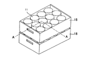
上記包装体(包装箱)は、例えば、図9及び図10に示すように、その保管及び搬送の際、多段積みされる。このとき、上記包装箱18は、包装箱18の高さ方向の中間部に配設された位置決めトレー16の貫通孔(収容予定のハニカム構造体11の横断面形状と同じ大きさ)に、ハニカム構造体11を縦置状態(ハニカム構造体の貫通孔方向を上下とする状態)で収容する形態であり、上段の包装箱18の荷重は、下段の包装箱18に収容されたハニカム構造体11(被包装物)により支持されている(特許文献1)。
For example, as shown in FIGS. 9 and 10, the packaging body (packaging box) is stacked in multiple stages during storage and transportation. At this time, the
しかしながら、近年、ハニカム構造体の大型化が進み、製品高さ(長さ)が大きくなりつつあり、30cm以上に及ぶ場合もある。このような場合、従来のようにハニカム構造体を縦置状態で収容すると、包装箱の高さが高くなる。一方、保管および搬送に使用する船倉および倉庫等の高さには通常制限がある。この制限高さまで、包装箱を積み重ねる場合に、包装箱の高さが高いと、高さの制限により、従来よりも数段少なく積まざるを得なくなる場合がある。このような場合には、デッドスペースが多くなり、船倉および倉庫等に収容できるハニカム構造体数が限定され、輸送効率が下がるという問題がある。
そこで、ハニカム構造体を横置状態(ハニカム構造体の貫通孔方向を水平とする状態)で収納すれば、包装体の高さの増加は防ぐことができる。しかしながら、ハニカム構造体は縦方向(ハニカム構造体の貫通孔に沿った方向)には強度が高いが、横方向(ハニカム構造体の貫通孔に垂直な方向)には強度が低いという特徴をもつ。したがって、ハニカム構造体を横置状態で収納した包装体を、従来のように多段積みする場合において、上段の包装体の荷重を下段の被包装物であるハニカム構造体により支持させようとすれば、下段のハニカム構造体が損傷するおそれがある。このような場合、下段のハニカム構造体の損傷を避けるために、結局、多段積みを避けざるを得ないという問題がある。 Therefore, if the honeycomb structure is stored in a horizontal state (a state in which the through hole direction of the honeycomb structure is horizontal), an increase in the height of the package can be prevented. However, the honeycomb structure is characterized by high strength in the longitudinal direction (direction along the through holes of the honeycomb structure) but low strength in the lateral direction (direction perpendicular to the through holes of the honeycomb structure). . Therefore, in the case where the packaging body in which the honeycomb structure is stored in a horizontal state is stacked in a multistage manner as in the past, if the load of the upper packaging body is to be supported by the honeycomb structure that is the lower packaging object, The lower honeycomb structure may be damaged. In such a case, in order to avoid damage to the lower honeycomb structure, there is a problem that multi-stage stacking must be avoided.
本発明は、このような従来技術の有する課題に鑑みてなされたものであり、その目的とするところは、従来に比して、製品を収納しても包装高さはそれほど高くならず、輸送効率の悪化の防止を図ることが可能でありかつ、ハニカム構造体の損傷を回避しつつ多段積みが可能であるハニカム構造体包装体を提供することにある。 The present invention has been made in view of such problems of the prior art, and the object of the present invention is that the packaging height is not so high even if the product is stored as compared with the prior art. An object of the present invention is to provide a honeycomb structure package that can prevent deterioration in efficiency and can be stacked in multiple stages while avoiding damage to the honeycomb structure.
本発明者らは上記課題を達成すべく鋭意検討した結果、以下に示すハニカム構造体包装体によって、上記課題を達成することが可能であることを見出し、本発明を完成するに至った。すなわち、本発明によれば、以下に示すハニカム構造体包装体が提供される。 As a result of intensive studies to achieve the above-mentioned problems, the present inventors have found that the above-described problems can be achieved by the following honeycomb structure package, and have completed the present invention. That is, according to the present invention, the following honeycomb structure package is provided.
[1] 板状の基台と、前記基台上に配設された、ハニカム構造体の側面部を支持する受台と、前記基台および前記受台の、下面および側面を包囲する5枚の剛性体パネルからなる直方体形状の箱体とを含むハニカム構造体包装体。 [1] A plate-shaped base, a pedestal disposed on the base and supporting a side surface portion of the honeycomb structure, and five sheets surrounding the lower surface and side surfaces of the base and the pedestal A honeycomb structure package including a rectangular parallelepiped box made of a rigid panel.
[2] 前記箱体はその下面に、前記箱体の側面の上端で形成される空間の形状と相補的形状を有する接続体を備え、複数の前記箱体を積み重ね可能である上記[1]に記載のハニカム構造体包装体。 [2] The box body includes a connection body having a shape complementary to a shape of a space formed at an upper end of a side surface of the box body on a lower surface thereof, and the plurality of box bodies can be stacked. The honeycomb structure package according to 1.
[3] 前記箱体は、その上部の開口を閉塞された状態で少なくとも1つの側面を開放可能である上記[2]に記載のハニカム構造体包装体。 [3] The honeycomb structure package according to the above [2], wherein the box body is capable of opening at least one side face in a state where an opening at an upper portion thereof is closed.
[4] 前記受台が、前記ハニカム構造体の側面部と相補形状の受部を有し、前記ハニカム構造体の側面部を下方から均等に支持する、前記[1]〜[3]のいずれかに記載のハニカム構造体包装体。
[4] Any of the above [1] to [3], wherein the cradle has a receiving portion complementary to the side surface portion of the honeycomb structure, and uniformly supports the side surface portion of the honeycomb structure from below. A honeycomb structure package according to
[5] 前記板状の基台の両面に受台が配設されている前記[1]〜[4]のいずれかに記載のハニカム構造体包装体。 [5] The honeycomb structure package according to any one of [1] to [4], wherein cradles are disposed on both surfaces of the plate-like base.
本発明のハニカム構造体包装体によれば、従来の縦置き収納に比して、ハニカム構造体を収納してもハニカム構造体包装体の高さはそれほど高くならず、輸送効率の悪化の防止を図ることが可能である。また、多段積みした際には、上段の荷重は下段の被包装物であるハニカム構造体ではなく、下段の箱体の剛性体パネルからなる側壁が担うので、ハニカム構造体の損傷を回避しつつ多段積みが可能であるという効果を奏する。 According to the honeycomb structure package of the present invention, the height of the honeycomb structure package is not so high even when the honeycomb structure is housed, as compared with the conventional vertical housing, and the deterioration of the transport efficiency is prevented. Can be achieved. In addition, when stacked in multiple stages, the load on the upper stage is not the honeycomb structure that is the lower package, but the side wall made of the rigid panel of the lower box, so that damage to the honeycomb structure is avoided. There is an effect that multi-stage stacking is possible.
以下、本発明を実施するための実施の形態を具体的に説明するが、本発明は以下の実施の形態に限定されるものではなく、本発明の趣旨を逸脱しない範囲で、当業者の通常の知識に基づいて、適宜設計の変更、改良等が加えられることが理解されるべきである。 Hereinafter, embodiments for carrying out the present invention will be specifically described. However, the present invention is not limited to the following embodiments, and is within the scope of the present invention. Based on this knowledge, it should be understood that design changes, improvements, etc. can be made as appropriate.
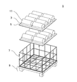
図1は、本発明に係るハニカム構造体包装体の一実施形態を説明する分解斜視図である。本発明のハニカム構造体包装体は、板状の基台5と、前記基台5上に配設された、ハニカム構造体の側面部(下方側)を支持する受台3と、前記基台5および前記受台3の、下面および側面を包囲する5枚の剛性体パネルからなる直方体形状の箱体7とから構成されている。ここで、ハニカム構造体11は、その貫通孔の入口側端面及び出口側端面と、入口側端面及び出口側端面を連結する側面部によりその外形を形成している。
FIG. 1 is an exploded perspective view for explaining an embodiment of a honeycomb structure package according to the present invention. The honeycomb structure package of the present invention includes a plate-
[1.受台]
本発明に係るハニカム構造体包装体1においては、ハニカム構造体11を、長手方向を横向きにした(ハニカム構造体の貫通孔方向が水平になるように横置きにした)状態で受台3上に載置する。受台3自体の形態は、ハニカム構造体の回転・移動を抑制できるものであれば特に限定されず、例えば、直方体の側面(および必要に応じて底面)で構成される四角枠の様なものでよい。簡便には、長手方向の支えまたはガイド(および必要に応じて底面)のみを受台としてハニカム構造体の回転を抑制し、隣り合ったハニカム構造体同士の端面間および/またはハニカム構造体の端面―箱体内側面間は、緩衝材等によって固定・衝突回避することとしてもよい。さらに、図2に示すように、ハニカム構造体11の側面部と相補形状の受部を有し、ハニカム構造体の側面部を下方から均等に支持する実施態様がより好ましい。受台3は基台5に固着されているのが好ましい。
[1. Cradle]
In the
本発明で用いる受台3としては、ポリオレフィン系樹脂のシート又は発泡シートや段ボール紙などの緩衝性を有するものが好ましい。ここで、ポリオレフィン系樹脂の発泡シートは、ポリエチレン、ポリプロピレン及びオレフィンを主体とする共重合体等の発泡シートを指すものである。特に、段ボール紙やポリエチレン樹脂の発泡シートは、弾力性に優れているため、本発明で用いる受台3として好適に用いることができる。
As the
[2.基台]
本実施形態においては、図1に示すように、8個のハニカム構造体11を、基台5に配設された受台3に載置した後、この基台5を二枚重ねて箱体7に格納している。図3は基台5の重ね合わせの様子を示す一部拡大図である。上述のようにハニカム構造体は長手方向に沿った方向に比べて長手方向に垂直な方向には強度が劣るが、ハニカム構造体1〜10個程度の重量には十分耐えうるものである。
[2. Base]
In the present embodiment, as shown in FIG. 1, after eight
本発明で用いる基台5としては、安価で、軽量で、適度な剛性を備えた材質のものが好ましい。好ましい基台5の材質としては、ダンボール、木材、鉄、アルミニウム、銅、ポリオレフィン系樹脂等が挙げられる。基台の形態は、ハニカム構造体や受台を支えることができ、且つ必要な剛性を維持できれば、特に制限はない。基台の形態としては、平板状・波板状・穴あき板状・格子状、等を適宜選択できる。
The
図4は、本発明の他の実施形態を示す図であり、ハニカム構造体を横向きに受台に載置した際の、ハニカム構造体、受台および基台の組みを2組み積み重ねた状態を示しており、側面側から見た一部拡大図である。図4に示すように、下段のハニカム構造体11と上段の基台5との間に弾性シート13を挟むのも、本発明の好適な実施形態の一例である。弾性シート13の材質としては、段ボール、ポリオレフィン系樹脂等を例示することができる。
FIG. 4 is a view showing another embodiment of the present invention, and shows a state in which two sets of the honeycomb structure, the cradle, and the base are stacked when the honeycomb structure is placed on the cradle sideways. It is shown and it is the partially expanded view seen from the side surface side. As shown in FIG. 4, it is also an example of a preferred embodiment of the present invention that an
図5は、本発明のさらに別の実施形態を示す図であり、ハニカム構造体を横向きに受台に載置した際の、ハニカム構造体、受台および基台の組みを2組み積み重ねた状態を示しており、側面側から見た一部拡大図である。図5に示すように、上段の基台5の両面に受台3を配設して、下段のハニカム構造体の保護を図るのも本発明の好適な実施の形態の一例である。なお、この実施形態の変形例として、基台5の両面に受台3を配設する代わりに、片面のみに受台3を配設した基台5を2枚使用して、受台3が配設されていない側を重ねることにより、同様の効果を実現することができる。
FIG. 5 is a view showing still another embodiment of the present invention, in which two sets of the honeycomb structure, the cradle, and the base are stacked when the honeycomb structure is horizontally placed on the cradle. FIG. 4 is a partially enlarged view seen from the side surface side. As shown in FIG. 5, it is also an example of a preferred embodiment of the present invention that the receiving
受台と基台は、別々に作製されたものを組み合わせ、必要に応じて接着して用いてもよいが、例えば、樹脂類等で材質を同じくする場合等には、一体成形して得ることもできる。 The cradle and base may be combined separately, and may be used as necessary. For example, when the material is the same for resins, etc. You can also.
[3.箱体]
本発明における箱体7は、基台5および受台3の、下面および側面を包囲するものである。箱体7は、5枚の剛性体パネルからなり、上面が開放された直方体形状をしている。本実施形態における箱体7は、図6に示すように、接続体9を介して上下に積み重ねることができる。なお、接続体9については、別に詳説する。また、図7に示すように、箱体7は、その上部の開口を閉塞された状態で少なくとも1つの側面を開放可能であるように構成するのが好ましい。図7は、3段積みされた箱体7のうち2段目の箱体7の側面を開放した状態を示す図である。
[3. Box]
The
このような構成は具体的には次のようにして実現することができる。少なくとも1つの側面を形成する剛性体パネルの下端と、底面を形成する剛性体パネルの対応する部位に蝶番を取り付け、当該側面を形成する剛性体パネルを蝶番を中心として回動自在とする。この際、当該側面を形成する剛性体パネルの上端付近および隣接する剛性体パネルの対応する位置に係止手段および被係止手段をそれぞれ配設すれば、必要時にのみ当該側面を開放することができる。 Specifically, such a configuration can be realized as follows. A hinge is attached to the lower end of the rigid body panel forming at least one side surface and a corresponding portion of the rigid body panel forming the bottom surface, and the rigid body panel forming the side surface is rotatable about the hinge. At this time, if the locking means and the locked means are disposed near the upper end of the rigid body panel forming the side surface and the corresponding position of the adjacent rigid body panel, the side surface can be opened only when necessary. it can.
箱体7の他の好適な実施形態としては、ハニカム構造体を収納していないときには、側面を底面に重なる様に折り畳んで、コンパクトにできるものを挙げることができる。このような構成は、例えば、隣り合う側面間に係止手段・被係止手段を配設し、更に各側面―底面間に蝶番を配設することによって、実現することができる。
As another preferred embodiment of the
箱体7の大きさは、特に制限は無い。しかしながら、箱体7の底面は、ハニカム構造体が、ハニカム構造体の長手方向に2〜4個、ハニカム構造体の長手方向に垂直な方向に2〜8個程度並べられる大きさであるのが好ましい。また、箱体7の高さは、貫通孔が水平となるように載置したハニカム構造体を2〜4個程度重ねられる程度の高さが好ましい。
The size of the
箱体7を構成する剛性体パネルの材質には、特に制限はない。鉄、アルミニウム、銅等の金属の網状物が剛性を十分に有しかつ軽量であるので好ましい。剛性体パネルの形態は、箱体7としたとき、内容物が飛び出すことなく収容でき、且つ必要な剛性を維持できれば、特に制限はない。剛性体パネルの形態としては、平板状・波板状・穴あき板状・格子状、等を適宜選択できる。
There is no restriction | limiting in particular in the material of the rigid body panel which comprises the
[4.その他]
箱体7の下方には、接続体9が配設されている。この接続体9は、箱体7の側面の上端で形成される空間の形状と相補的形状を有しており、複数の箱体7を上下に複数重ねた場合に、重ねられた箱体が相互にずれを生じないように作用する。また、この接続体9は、箱体が一個単独の場合には、箱体7の脚部として働く。接続体9の材質には特に制限はない。上記箱体7と同じ材質とすることができる。
[4. Others]
A connecting
また、箱体7にハニカム構造体を縦方向に複数段に重ねて収納する際には、下段のハニカム構造体と上段の基台5との間に段積み用の中間トレイを配設しても良い。
Further, when the honeycomb structure is stored in the
図8は本発明の変形例を示す図である。図8においては、箱体7の側壁を構成する剛性体パネルのうち、少なくとも互いに対向する1組のパネルの対応する部位に係止体15が配設されている。係止体15は、剛性体パネルに基台5を係止可能とするための部材である。基台5は係止体15を介して剛性体パネルに支持される。なお、係止体15は、剛性体パネル側ではなく、基台5側に配設しても良い。このような構成により、箱体7中にハニカム構造体を上下方向に複数段収納する際に、下段のハニカム構造体に上段のハニカム構造体等の荷重がかからないという効果が得られる。また、段積みの不安定さを解消する効果も奏する。さらに、段積み用の中間トレイ等を使用する必要もない。
FIG. 8 is a diagram showing a modification of the present invention. In FIG. 8, among the rigid body panels constituting the side wall of the
箱体7とハニカム構造体11等との間には、緩衝体等を配設してもよい。このように構成すれば、箱体7を構成する剛性体パネルとハニカム構造体とが輸送中等に直接触れ合ってハニカム構造体が損傷することを防止することができる。また、保管時に埃等がハニカム構造体に付着することを防止することもできる。緩衝体の材質には特に制限はない。ポリオレフィン系樹脂等、緩衝物として一般に広く用いられているものを使用することができる。
A buffer or the like may be disposed between the
保管時におけるハニカム構造体への埃等の付着を防止するためには、箱体7の外側からストレッチ包装を行うのも好ましい実施態様の一つである。
In order to prevent dust and the like from adhering to the honeycomb structure during storage, one preferred embodiment is to perform stretch packaging from the outside of the
以上説明した通り、本発明の包装体は、ハニカム構造体という破損し易い製品を破損することなく良好に保管及び効率よく輸送することができ、産業上の利用価値が大なるものである。 As described above, the package of the present invention can be stored and efficiently transported without damaging a fragile product such as a honeycomb structure, and has a great industrial utility value.
1:包装体、3:受台、5:基台、7:箱体、9:接続体、11:ハニカム構造体、13:弾性シート、15:係止体、16:位置決めトレー、18:包装箱。 1: packaging body, 3: receiving base, 5: base, 7: box, 9: connection body, 11: honeycomb structure, 13: elastic sheet, 15: locking body, 16: positioning tray, 18: packaging box.
Claims (5)
前記基台上に配設された、ハニカム構造体の側面部を支持する受台と、
前記基台および前記受台の、下面および側面を包囲する5枚の剛性体パネルからなる直方体形状の箱体とを含むハニカム構造体包装体。 A plate-shaped base;
A pedestal disposed on the base for supporting a side surface portion of the honeycomb structure;
A honeycomb structure package including a rectangular parallelepiped box made of five rigid panels surrounding the lower surface and side surfaces of the base and the cradle.
Priority Applications (4)
| Application Number | Priority Date | Filing Date | Title |
|---|---|---|---|
| JP2008230882A JP2010064758A (en) | 2008-09-09 | 2008-09-09 | Honeycomb structure package |
| US12/549,840 US20100059521A1 (en) | 2008-09-09 | 2009-08-28 | Honeycomb structure package |
| EP09252134A EP2161209A1 (en) | 2008-09-09 | 2009-09-04 | Honeycomb structure package |
| CN200910171136A CN101670908A (en) | 2008-09-09 | 2009-09-08 | Honeycomb structure package |
Applications Claiming Priority (1)
| Application Number | Priority Date | Filing Date | Title |
|---|---|---|---|
| JP2008230882A JP2010064758A (en) | 2008-09-09 | 2008-09-09 | Honeycomb structure package |
Publications (1)
| Publication Number | Publication Date |
|---|---|
| JP2010064758A true JP2010064758A (en) | 2010-03-25 |
Family
ID=41350285
Family Applications (1)
| Application Number | Title | Priority Date | Filing Date |
|---|---|---|---|
| JP2008230882A Pending JP2010064758A (en) | 2008-09-09 | 2008-09-09 | Honeycomb structure package |
Country Status (4)
| Country | Link |
|---|---|
| US (1) | US20100059521A1 (en) |
| EP (1) | EP2161209A1 (en) |
| JP (1) | JP2010064758A (en) |
| CN (1) | CN101670908A (en) |
Cited By (2)
| Publication number | Priority date | Publication date | Assignee | Title |
|---|---|---|---|---|
| JP2011136758A (en) * | 2010-08-20 | 2011-07-14 | Ngk Insulators Ltd | Tray for packing honeycomb structure |
| JP2021142989A (en) * | 2020-03-10 | 2021-09-24 | 日本碍子株式会社 | Tray for prismatic honeycomb structure |
Families Citing this family (2)
| Publication number | Priority date | Publication date | Assignee | Title |
|---|---|---|---|---|
| CN104210994B (en) * | 2014-09-02 | 2017-05-31 | 山东亨圆铜业有限公司 | One kind lifting honeycomb fashion copper pipe transport box |
| CN108789331A (en) * | 2018-06-26 | 2018-11-13 | 安徽中盛罐业股份有限公司 | A kind of packing jar rack |
Citations (7)
| Publication number | Priority date | Publication date | Assignee | Title |
|---|---|---|---|---|
| JPH06115543A (en) * | 1992-09-28 | 1994-04-26 | Suzuki Motor Corp | Plural stage packing box |
| JP3093181U (en) * | 2002-08-02 | 2003-04-18 | 中国国際海運集装箱(集団)股▲ふん▼有限公司 | Lightweight and disassemblable grid-type metal pallet box |
| JP2003267374A (en) * | 2002-03-12 | 2003-09-25 | Panahome Corp | Packaging device for transportation |
| JP2004299686A (en) * | 2003-03-28 | 2004-10-28 | Ohbayashi Corp | Container, and method for discharging content from container |
| JP2005041523A (en) * | 2003-07-22 | 2005-02-17 | Sanko Co Ltd | Holding/transporting implement for rolled material |
| JP2005088999A (en) * | 2003-08-08 | 2005-04-07 | Seiki Juko Kk | Pallet |
| JP2007246167A (en) * | 2006-02-17 | 2007-09-27 | Ngk Insulators Ltd | Package |
Family Cites Families (5)
| Publication number | Priority date | Publication date | Assignee | Title |
|---|---|---|---|---|
| US5704483A (en) * | 1995-10-26 | 1998-01-06 | Shoreline Container Inc. | Folding tray type container |
| JP3005187B2 (en) * | 1996-02-29 | 2000-01-31 | 日本碍子株式会社 | Honeycomb structure packing box |
| US6640975B2 (en) * | 2001-08-21 | 2003-11-04 | Conagra Grocery Products Company | Stackable self-aligning container |
| JP2003112771A (en) | 2001-10-02 | 2003-04-18 | Ngk Insulators Ltd | Package |
| US20070193912A1 (en) * | 2006-02-17 | 2007-08-23 | Ngk Insulators, Ltd. | Package |
-
2008
- 2008-09-09 JP JP2008230882A patent/JP2010064758A/en active Pending
-
2009
- 2009-08-28 US US12/549,840 patent/US20100059521A1/en not_active Abandoned
- 2009-09-04 EP EP09252134A patent/EP2161209A1/en not_active Withdrawn
- 2009-09-08 CN CN200910171136A patent/CN101670908A/en active Pending
Patent Citations (7)
| Publication number | Priority date | Publication date | Assignee | Title |
|---|---|---|---|---|
| JPH06115543A (en) * | 1992-09-28 | 1994-04-26 | Suzuki Motor Corp | Plural stage packing box |
| JP2003267374A (en) * | 2002-03-12 | 2003-09-25 | Panahome Corp | Packaging device for transportation |
| JP3093181U (en) * | 2002-08-02 | 2003-04-18 | 中国国際海運集装箱(集団)股▲ふん▼有限公司 | Lightweight and disassemblable grid-type metal pallet box |
| JP2004299686A (en) * | 2003-03-28 | 2004-10-28 | Ohbayashi Corp | Container, and method for discharging content from container |
| JP2005041523A (en) * | 2003-07-22 | 2005-02-17 | Sanko Co Ltd | Holding/transporting implement for rolled material |
| JP2005088999A (en) * | 2003-08-08 | 2005-04-07 | Seiki Juko Kk | Pallet |
| JP2007246167A (en) * | 2006-02-17 | 2007-09-27 | Ngk Insulators Ltd | Package |
Cited By (3)
| Publication number | Priority date | Publication date | Assignee | Title |
|---|---|---|---|---|
| JP2011136758A (en) * | 2010-08-20 | 2011-07-14 | Ngk Insulators Ltd | Tray for packing honeycomb structure |
| JP2021142989A (en) * | 2020-03-10 | 2021-09-24 | 日本碍子株式会社 | Tray for prismatic honeycomb structure |
| JP7361641B2 (en) | 2020-03-10 | 2023-10-16 | 日本碍子株式会社 | Tray for prismatic honeycomb structure |
Also Published As
| Publication number | Publication date |
|---|---|
| EP2161209A1 (en) | 2010-03-10 |
| US20100059521A1 (en) | 2010-03-11 |
| CN101670908A (en) | 2010-03-17 |
Similar Documents
| Publication | Publication Date | Title |
|---|---|---|
| CA2581849A1 (en) | Packaging system for shipping a plurality of items | |
| JP2011037474A (en) | Solar battery panel packaging material | |
| WO2011114391A1 (en) | Package unit and loading method and loading structure therefor | |
| JP2010064758A (en) | Honeycomb structure package | |
| JP2008037469A (en) | Tray for brittle column | |
| JP2011140339A (en) | Component packaging tray | |
| JP4210693B2 (en) | Tray and container using it | |
| EP1820741B1 (en) | Package | |
| JPH09226837A (en) | Packing box for honeycomb structure | |
| JP5950184B2 (en) | Package of ceramic honeycomb member | |
| JP4636065B2 (en) | Packing box | |
| JP5205178B2 (en) | Connecting container | |
| KR102202860B1 (en) | Packing box | |
| JP2007191168A (en) | Packing box | |
| JP2005313913A (en) | Transportation container | |
| JP2015020747A (en) | Packing box | |
| JP2007246167A (en) | Package | |
| JP4181726B2 (en) | Roll product shipping container | |
| CN201437420U (en) | Heavy-load packaging box and single-deck pallets thereof | |
| JP2003170963A (en) | Bottle body storage box | |
| JP2005053578A (en) | Container for packaging and transporting | |
| JP2005335747A (en) | Rack for roll product | |
| JP2010155624A (en) | Modular container | |
| JP2008094488A (en) | Transporting box for roll product | |
| JP2017178425A (en) | Assembly packaging container and stacked set thereof |
Legal Events
| Date | Code | Title | Description |
|---|---|---|---|
| A621 | Written request for application examination |
Free format text: JAPANESE INTERMEDIATE CODE: A621 Effective date: 20110520 |
|
| A977 | Report on retrieval |
Free format text: JAPANESE INTERMEDIATE CODE: A971007 Effective date: 20121005 |
|
| A131 | Notification of reasons for refusal |
Free format text: JAPANESE INTERMEDIATE CODE: A131 Effective date: 20121113 |
|
| A02 | Decision of refusal |
Free format text: JAPANESE INTERMEDIATE CODE: A02 Effective date: 20130423 |