JP2010064756A - Package made of corrugated fiberboard - Google Patents
Package made of corrugated fiberboard Download PDFInfo
- Publication number
- JP2010064756A JP2010064756A JP2008230424A JP2008230424A JP2010064756A JP 2010064756 A JP2010064756 A JP 2010064756A JP 2008230424 A JP2008230424 A JP 2008230424A JP 2008230424 A JP2008230424 A JP 2008230424A JP 2010064756 A JP2010064756 A JP 2010064756A
- Authority
- JP
- Japan
- Prior art keywords
- side plate
- cut
- unpacking
- height direction
- packaging tool
- Prior art date
- Legal status (The legal status is an assumption and is not a legal conclusion. Google has not performed a legal analysis and makes no representation as to the accuracy of the status listed.)
- Granted
Links
- 239000011096 corrugated fiberboard Substances 0.000 title abstract 2
- 238000004806 packaging method and process Methods 0.000 claims description 54
- 238000005520 cutting process Methods 0.000 claims description 29
- 238000005452 bending Methods 0.000 claims description 3
- 230000002093 peripheral effect Effects 0.000 abstract description 2
- 238000012856 packing Methods 0.000 description 48
- 239000000123 paper Substances 0.000 description 8
- 230000007423 decrease Effects 0.000 description 4
- XLYOFNOQVPJJNP-UHFFFAOYSA-N water Substances O XLYOFNOQVPJJNP-UHFFFAOYSA-N 0.000 description 4
- 238000009434 installation Methods 0.000 description 3
- 230000000694 effects Effects 0.000 description 2
- 230000006698 induction Effects 0.000 description 2
- 230000000903 blocking effect Effects 0.000 description 1
- 230000003247 decreasing effect Effects 0.000 description 1
- 230000007257 malfunction Effects 0.000 description 1
- 238000000034 method Methods 0.000 description 1
- 238000012986 modification Methods 0.000 description 1
- 230000004048 modification Effects 0.000 description 1
- 239000003507 refrigerant Substances 0.000 description 1
- 238000005406 washing Methods 0.000 description 1
- 238000004804 winding Methods 0.000 description 1
Images


Abstract
Description
この発明は、梱包製品をその周囲を覆うように梱包する段ボール製梱包具に関する。 The present invention relates to a corrugated cardboard packing tool for packing a packaged product so as to cover its periphery.
家電製品等は、設置場所に到着するまでは、段ボール製の梱包具によって梱包されており、設置場所周辺において、段ボール製梱包具を開梱するのが通例である。 Home appliances and the like are packed in a cardboard packaging until they arrive at the installation location, and the cardboard packaging is usually unpacked around the installation location.
また下記特許文献1には、冷蔵庫、洗濯機等のような背の高い大型製品を梱包するための段ボール製梱包具が開示されているが、このような大型製品においても、上記と同様に、設置場所周辺で、梱包具を開梱するようにしている。
Moreover, in the following
ところで、このような大型製品の梱包具を開梱する場合には例えば、大型製品に対し梱包具を上方へ抜き取って、梱包具を取り外したり、あるいはカッターナイフ等を用いて、梱包具を切り裂いて、梱包具を取り外すのが一般的である。
しかしながら、梱包具を上方へ抜き取る場合には、製品の背丈が高いと、梱包具を製品の背丈よりも高い位置まで持ち上げる必要があるため、梱包具の持ち上げ量が非常に多くなり、開梱するのが困難になる、という問題があった。そればかりか、屋内の場合には、梱包具を製品上端から抜き取る際に、梱包具が天井に当たって、梱包具を簡単に抜き取ることができないこともある。 However, when pulling out the packing tool upward, if the height of the product is high, it is necessary to lift the packing tool to a position higher than the height of the product. There was a problem that it became difficult. In addition, in the case of indoors, when the packing tool is pulled out from the upper end of the product, the packing tool may hit the ceiling and the packing tool may not be easily pulled out.
またカッターナイフによって梱包具を切り裂く場合には、カッターナイフで梱包製品を傷付けないように、梱包具を慎重にゆっくりと切り裂いていく必要があり、作業者にとって負担が大きく、簡単に開梱することができない、という問題が発生する。 In addition, when cutting a packing tool with a cutter knife, it is necessary to carefully and slowly tear the packing tool so as not to damage the packed product with the cutter knife. The problem of not being able to occur.
この発明は、上記の課題に鑑みてなされたものであり、大型製品を梱包するように構成しても、簡単かつ確実に開梱することができる段ボール製梱包具を提供することを目的とする。 The present invention has been made in view of the above problems, and an object of the present invention is to provide a corrugated cardboard packaging that can be easily and reliably unpacked even when configured to pack large products. .
上記目的を達成するため、本発明は以下の構成を要旨とするものである。 In order to achieve the above object, the present invention has the following structure.
[1] 3枚以上複数の側板部が、梱包製品の周囲を閉塞し得る態様に周方向に連設されるとともに、各側板部が、段目方向を梱包製品の高さ方向に対応させた段ボールによって構成される段ボール製梱包具であって、
前記複数の側板部のうちいずれか1つの側板部が、開梱用側板部として構成され、
前記開梱用側板部に、高さ方向中間部における周方向一方寄りの位置に、切り開き開始部が設けられ、
前記開梱用側板部に、その上端縁の周方向他方寄りの位置から、前記切り開き開始部の上端にかけて斜め方向に沿って上側破断誘導線が設けられるとともに、
前記開梱用側板部に、その下端縁の周方向他方寄りの位置から、前記切り開き開始部の下端にかけて斜め方向に沿って下側破断誘導線が設けられ、
前記上下両側破断誘導線および前記切り開き開始部を境界線にして、前記開梱用側板部が周方向に区分けされて、その他方側の領域が切り開き領域として構成され、
開口された状態の前記切り開き開始部に対応する部分を起点にして、前記切り開き領域が外側に開き操作されることにより、前記開梱用側板部が前記上下両側破断誘導線に沿って破断されて周方向に切り離されるように構成されたことを特徴とする段ボール製梱包具。
[1] Three or more side plate portions are continuously provided in the circumferential direction so that the periphery of the packaged product can be closed, and each side plate portion has the step direction corresponding to the height direction of the packaged product. A corrugated packaging made of corrugated cardboard,
Any one side plate portion of the plurality of side plate portions is configured as an unpacking side plate portion,
In the unpacking side plate part, a slit opening start part is provided at a position closer to one side in the circumferential direction in the intermediate part in the height direction,
On the unpacking side plate part, an upper fracture guide line is provided along an oblique direction from a position near the other end in the circumferential direction of the upper end edge to the upper end of the slit opening start part,
On the unpacking side plate portion, a lower break guide line is provided along a diagonal direction from a position closer to the other end in the circumferential direction of the lower end edge to a lower end of the slit opening start portion,
The unwrapping side plate is divided in the circumferential direction with the upper and lower side breakage guide lines and the cut start part as a boundary line, and the other side area is configured as a cut area,
Starting from a portion corresponding to the opening start portion in the opened state, the opening region is opened outwardly, whereby the unpacking side plate portion is broken along the upper and lower both-side break guide lines. A corrugated cardboard packaging tool configured to be cut off in the circumferential direction.
[2] 前記切り開き開始部は、その一部が予め開口された開口部として構成されるとともに、残りの部分が、切取操作によって開口可能な切取許容部として構成される前項1に記載の段ボール製梱包具。 [2] The cut opening start portion is configured as an opening portion that is partially opened in advance, and the remaining portion is configured as a cutting allowance portion that can be opened by a cutting operation. Packing tool.
[3] 前記上下両側破断誘導線の少なくとも一方の破断誘導線の一部に、高さ方向に対し平行な高さ方向直線部が設けられる前項1または2に記載の段ボール製梱包具。
[3] The cardboard packaging device according to the
[4] 前記上下両側破断誘導線の各一部に、高さ方向に対し平行な高さ方向直線部がそれぞれ設けられるとともに、各高さ方向直線部が、互いに周方向に位置をずらせて配置される前項1〜3のいずれか1項に記載の段ボール製梱包具。
[4] A part in each of the upper and lower both-side break guide lines is provided with a height direction straight line portion parallel to the height direction, and the height direction straight line portions are shifted from each other in the circumferential direction. The cardboard packaging tool according to any one of the preceding
[5] 前記上側破断誘導線の上端が、前記開梱用側板部の上端縁における他方側の端部に配置される前項1〜4のいずれか1項に記載の段ボール製梱包具。
[5] The corrugated cardboard packaging tool according to any one of the preceding
[6] 前記上側破断誘導線の上端を含む上側部に、高さ方向に対し傾斜する斜め方向直線部が設けられる前項5に記載の段ボール製梱包具。 [6] The corrugated cardboard packaging tool described in [5] above, wherein an oblique direction linear portion that is inclined with respect to a height direction is provided on an upper portion including an upper end of the upper fracture guide line.
[7] 前記下側破断誘導線の下端が、前記開梱用側板部の下端縁における他方側の端部に配置される前項1〜6のいずれか1項に記載の段ボール製梱包具。
[7] The cardboard packaging tool according to any one of the preceding
[8] 前記下側破断誘導線の下端を含む下側部に、高さ方向に対し傾斜する斜め方向直線部が設けられる前項7に記載の段ボール製梱包具。 [8] The corrugated cardboard packaging tool described in [7], wherein an oblique straight line portion that is inclined with respect to a height direction is provided on a lower side portion including a lower end of the lower fracture guide line.
[9] 前記切り開き開始部は、その少なくとも一部に、切取操作によって開口可能な切取許容部が設けられ、
前記切取許容部は、高さ方向に延びる縦長帯状に形成されるとともに、その切取許容部の両側縁に沿って中間破断誘導線が設けられ、
前記切取許容部は、その上下両端のいずれか一方を起点にして、外側に引張操作されることにより、切り取られるように構成され、
前記切取許容部に、周方向に延びる折れ曲げ線が、高さ方向に間隔をおいて複数設けられる前項1〜8のいずれか1項に記載の段ボール製梱包具。
[9] The cut opening start portion is provided at least at a part thereof with a cutting allowance portion that can be opened by a cutting operation.
The cut-off permission portion is formed in a vertically long strip shape extending in the height direction, and an intermediate break guide line is provided along both side edges of the cut-off permission portion,
The cutting allowance portion is configured to be cut by being pulled outward from either one of its upper and lower ends,
9. The corrugated cardboard packaging tool according to any one of the preceding
[10] 隣り合う側板部の各間のうち、いずれかの側板部間が継ぎ合わされて連設されるとともに、継ぎ合わされた2つの側板部のいずれか一方が、前記開梱用側板部として構成される前項1〜9のいずれか1項に記載の段ボール製梱包具。
[10] Among each of the adjacent side plate portions, any one of the side plate portions is joined and connected, and either one of the two joined side plate portions is configured as the unpacking side plate portion. The cardboard packaging tool according to any one of the preceding
なお本発明においては、以下の好適な構成も採用することができる。 In the present invention, the following preferred configurations can also be employed.
[11] 梱包製品の外面に、梱包製品に関連した情報が表示された情報表示部が設けられ、その情報表示部に対応して前記開口部が配置される前項2に記載の段ボール製梱包具。
[11] The cardboard packaging device according to
[12] 複数の側板部のうち、前記開梱用側板部を除く側板部が、梱包具の荷積み配送時における接地面に構成される前項1〜11のいずれか1項に記載の段ボール製梱包具。 [12] Among the plurality of side plate portions, the side plate portion excluding the unpacking side plate portion is formed on the ground contact surface during loading and delivery of the packing tool. Packing tool.
[13] 前記側板部が、3枚の平板紙の各間に波板紙がそれぞれ介在された2層構造の強化段ボールによって構成される前項1〜12のいずれか1項に記載の段ボール製梱包具。
[13] The corrugated cardboard packaging tool according to any one of the preceding
発明[1]の段ボール製梱包具によれば、開梱時には、開梱用側板部の切り開き領域を周方向に沿って開き操作するだけで簡単に、開梱用側板部を周方向に切り離すことができて確実に開梱することができる。 According to the cardboard packaging tool of the invention [1], at the time of unpacking, the unpacking side plate can be easily separated in the circumferential direction simply by opening the opening region of the unpacking side plate along the circumferential direction. And can be unpacked reliably.
発明[2]の段ボール製梱包具によれば、開梱時における切り開き開始部の開口寸法を十分大きく確保することができ、開梱作業をより一層簡単に行うことができる。 According to the cardboard packaging tool of the invention [2], it is possible to ensure a sufficiently large opening dimension of the slit opening start portion at the time of unpacking, and the unpacking operation can be performed more easily.
発明[3]の段ボール製梱包具によれば、背の高い大型製品を梱包できるように構成したとしても、上記と同様に簡単かつ確実に開梱することができる。 According to the corrugated cardboard packing tool of the invention [3], even if it is configured to be able to pack a large tall product, it can be unpacked simply and reliably as described above.
発明[4]の段ボール製梱包具によれば、高さ方向に平行な複数の破断誘導線が、直列に配置されることがなく、十分な強度を確保することができる。 According to the cardboard packaging tool of the invention [4], a plurality of break guide wires parallel to the height direction are not arranged in series, and sufficient strength can be ensured.
発明[5]〜[8]の段ボール製梱包具によれば、強度が低下するのを防止することができる。 According to the cardboard packaging tools of the inventions [5] to [8], it is possible to prevent the strength from being lowered.
発明[9]の段ボール製梱包具によれば、切取許容部をスムーズに切り取ることができて、切り開き開始部を確実に開口することができる。 According to the corrugated cardboard packaging tool of the invention [9], it is possible to smoothly cut the cut-permitting portion and to reliably open the cut opening start portion.
発明[10]の段ボール製梱包具によれば、強度が低下するのを、より確実に防止することができる。 According to the cardboard packaging tool of the invention [10], it is possible to more reliably prevent the strength from being lowered.
好適構成[11]の段ボール製梱包具によれば、梱包状態において、開口部を介して製品情報表示部を視認することができ、開梱せずに梱包製品の情報を正確に把握することができる。 According to the cardboard packaging tool of the preferred configuration [11], the product information display unit can be visually recognized through the opening in the packaged state, and the information on the packaged product can be accurately grasped without unpacking. it can.
好適構成[12]の段ボール製梱包具によれば、破損や破裂等の不具合を防止しつつ、トラック荷台等に対する積み卸し作業を支障なく行うことができる。 According to the corrugated cardboard packaging tool having the preferred configuration [12], loading and unloading work on a truck bed can be performed without any trouble while preventing problems such as breakage and rupture.
好適構成[13]の段ボール製梱包具によれば、より一層高い強度を得ることができる。 According to the cardboard packaging tool having the preferred configuration [13], even higher strength can be obtained.
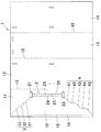
図1〜4はこの発明の第1実施形態である段ボール製梱包具を示す図である。これらの図に示すように、この段ボール製梱包具(1)は、高さが2m以上もある電気式室外給湯機(自然冷媒ヒートポンプ給湯機)の貯湯ユニット(貯湯タンク)を梱包するものである。この梱包具(1)は、梱包製品における前後左右の周囲4面を閉塞するための4枚の縦長の側板部(11)〜(14)を備えている。各側板部(11)〜(14)は、隣り合う側板部間の折り曲げ線(15)に沿って90°折り曲げられることにより、周方向に連設される態様に並んで配置され、全体として縦長の角筒状に形成されている。 1-4 is a figure which shows the cardboard packaging tool which is 1st Embodiment of this invention. As shown in these drawings, this corrugated cardboard packing tool (1) is for packing a hot water storage unit (hot water storage tank) of an electric outdoor water heater (natural refrigerant heat pump water heater) having a height of 2 m or more. . This packing tool (1) is provided with four vertically long side plate portions (11) to (14) for closing four front, rear, left and right peripheral surfaces of the packed product. The side plate portions (11) to (14) are arranged side by side in a circumferentially arranged manner by being bent by 90 ° along a fold line (15) between adjacent side plate portions, and are vertically long as a whole. It is formed in a square tube shape.
なお本第1実施形態において、上下左右等の各方向は、図1の方向を基準としている。すなわち同図の紙面に向かって、左右方向を「左右方向(周方向)」、右側を「右側(一方側)」とし、左側を「左側(他方側)」とし、上下方向は「上下方向(高さ方向)」として説明する。 In the first embodiment, directions such as up, down, left, and right are based on the directions in FIG. In other words, the left and right direction is “left and right direction (circumferential direction)”, the right side is “right side (one side)”, the left side is “left side (the other side)”, and the up and down direction is “up and down direction ( (Height direction) ”.
さらに第1実施形態では、発明の理解を容易にするため、図1において、左端の側板部(11)を「前側板部」、左から2番目の側板部(12)を「右側板部」、左から3番目の側板部(13)を「後側板部」、右端の側板部(14)を「左側板部」として説明する。 Further, in the first embodiment, in order to facilitate understanding of the invention, in FIG. 1, the left side plate (11) is the “front plate” and the second side plate (12) from the left is the “right plate”. The third side plate (13) from the left will be described as a “rear side plate”, and the right side plate (14) will be described as a “left side plate”.
各側板部(11)〜(14)は、3枚の平板紙(ライナー原紙)と、2枚の波板紙(中しん原紙)とが交互に積層された、いわゆる「表紙+中しん+中紙+中しん+裏紙」タイプの2層構造の強化段ボールによって構成されている。さらに各側板部(11)〜(14)は、段目方向を高さ方向に一致させ、流れ方向(波寄せ方向)を周方向(左右方向)に一致させるように構成されている。 Each of the side plate portions (11) to (14) is a so-called “cover + medium shin + inner paper” in which three flat paper sheets (liner base paper) and two corrugated paper sheets (medium base paper) are alternately laminated. It consists of reinforced corrugated cardboard with a two-layer structure of “+ medium shin + back paper” type. Furthermore, each side plate part (11)-(14) is comprised so that a step direction may be made to correspond to a height direction and a flow direction (wave approach direction) may be made to correspond to the circumferential direction (left-right direction).
側板部(11)〜(14)のうち、前側板部(11)と、左側板部(14)とは継ぎ合わされている。すなわち前側板部(1)の左側縁部には、継ぎ代(15)が設けられ、この継ぎ代(16)が左側板部(14)の右側縁部に重ね合わせた状態で貼り付けられている。 Of the side plate portions (11) to (14), the front side plate portion (11) and the left side plate portion (14) are joined together. That is, a joint margin (15) is provided on the left side edge portion of the front side plate portion (1), and the joint margin (16) is attached in a state of being overlapped with the right side edge portion of the left side plate portion (14). Yes.
本実施形態において、前側板部(11)が開梱用側板部として構成されており、この前側板部(11)に、切り開き開始部(2)、上側破断誘導線(3)、下側破断誘導線(4)が設けられている。 In the present embodiment, the front side plate portion (11) is configured as a side plate portion for unpacking, and the front side plate portion (11) is provided with a slit opening start portion (2), an upper breaking guide line (3), and a lower breaking portion. A guide wire (4) is provided.
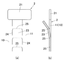
切り開き開始部(2)は、前側板部(11)の高さ方向中間部における右側部に、高さ方向に沿って設けられており、縦長の形状を有している。この切り開き開始部(2)は、上下両端に設けられた横長矩形状の開口部(21)(22)と、両開口部(21)(22)間にその間を結ぶように設けられた縦長帯状の切取許容部(23)とを備えている。 The slit opening start portion (2) is provided along the height direction on the right side portion in the height direction intermediate portion of the front side plate portion (11), and has a vertically long shape. The slit opening start portion (2) has a horizontally-long rectangular opening (21) (22) provided at both upper and lower ends, and a vertically long belt-like shape provided between the openings (21) (22). And a cutting allowance portion (23).
開口部(21)(22)は、その領域に対応する段ボールが切り取られることによって形成されており、前側板部(11)を貫通する貫通孔によって構成されている。 The openings (21) and (22) are formed by cutting out corrugated cardboard corresponding to the region, and are constituted by through holes that penetrate the front plate (11).
切取許容部(23)は、両側縁部に沿ってジッパー状の切れ目線(24)(24)が設けられている。両切れ目線(24)(24)は、その上端が上側開口部(21)に達するとともに、下端が下側開口部(21)に達する位置まで形成されて、高さ方向(段目方向)に沿って配置されている。従って、作業者は例えば上側開口部(21)を介して、切取許容部(23)の上端部を摘んで、手前に引っ張れば(開き操作すれば)、前側板部(11)が、切れ目線(24)(24)に沿って、上端から下端に向けて切り裂かれていき、閉塞部(23)が切り取られて、切り開き開始部(2)の全域が開口されるようになっている。 The cutting allowance portion (23) is provided with zipper-like cut lines (24) and (24) along both side edges. Both cut lines (24) and (24) are formed up to a position where the upper end reaches the upper opening (21) and the lower end reaches the lower opening (21), in the height direction (step direction). Are arranged along. Therefore, for example, if the operator grasps the upper end portion of the cut-off permission portion (23) through the upper opening (21) and pulls it toward the front (opening operation), the front plate portion (11) (24) It is torn along the upper end from the upper end along (24), the blocking portion (23) is cut off, and the entire region of the opening start portion (2) is opened.
なお図6に示すように本実施形態において、切取許容部(23)には左右方向(周方向)に延びる複数のV溝状の折り曲げ線(25)を、高さ方向(上下方向)に沿って等間隔おきに形成しているため、切取許容部(23)をスムーズに切り取ることができる。 As shown in FIG. 6, in this embodiment, a plurality of V-groove fold lines (25) extending in the left-right direction (circumferential direction) are provided along the height direction (vertical direction) in the cutting allowance portion (23). Therefore, the cut-permitting portion (23) can be cut out smoothly.
すなわち縦長帯状切取許容部(23)は、段目方向(高さ方向)に沿って形成されて、段目方向に沿って上方から下方に向けて切り取るよう構成されているため、仮に折り曲げ線(25)が形成されない場合には、切取許容部(23)を切り取っていく際に、折れ曲がり難く、切取許容部(23)をスムーズに切り取ることができなくなってしまう。 That is, the vertically long strip-shaped permissible portion (23) is formed along the step direction (height direction) and is cut from the upper side to the lower side along the step direction. When 25) is not formed, it is difficult to bend when the cutting allowance portion (23) is cut, and the cutting allowance portion (23) cannot be cut smoothly.
そこで本実施形態では、切取許容部(23)に、流れ方向(左右方向)に平行な複数の折り曲げ線(25)を、段目方向に等間隔おきに形成しているため、切取許容部(23)を上から下へ切り取っていく際に、切取許容部(23)が、折り曲げ線(25)の部分において無理なく外側に順次折れ曲がっていく。従って切取許容部(23)を段目方向に沿って簡単かつスムーズに切り取っていくことができる。 Therefore, in the present embodiment, a plurality of fold lines (25) parallel to the flow direction (left and right direction) are formed at equal intervals in the step direction in the cutting allowance portion (23). When cutting 23) from the top to the bottom, the cut-off allowable portion (23) bends to the outside without difficulty at the fold line (25). Therefore, the cutting allowance part (23) can be cut out easily and smoothly along the step direction.
ここで本実施形態においては、切取許容部(23)の両側に設けられたジッパー状の切れ目線(24)(24)が、中間破断誘導線として構成されている。 Here, in the present embodiment, zipper-like cut lines (24) and (24) provided on both sides of the cut-off permission portion (23) are configured as intermediate breakage induction lines.
また本実施形態においては、上側および下側開口部(21)(22)のうち少なくともいずれか一方が、覗き窓として構成されている。すなわち、梱包される製品の外表面には、製品名、種類、製品番号等の製品に関する情報が表示された製品情報表示部が設けられているが、この製品情報表示部に対応する位置に、上下両側開口部(21)(22)のうち少なくともいずれか一方が配置されて、覗き窓として構成されている。従って作業者は、梱包状態において、この覗き窓を介して製品情報表示部を視認することができ、開梱せずに梱包製品の情報を正確に把握することができる。このため例えば、製品の種類を不用意に間違えてしまう等の不具合を確実に防止することができる。 In the present embodiment, at least one of the upper and lower openings (21) and (22) is configured as a viewing window. That is, on the outer surface of the product to be packed, there is provided a product information display section on which information about the product such as product name, type, product number, etc. is displayed, but at a position corresponding to this product information display section, At least one of the upper and lower side openings (21) and (22) is arranged to constitute a viewing window. Therefore, the worker can visually recognize the product information display unit through the viewing window in the packed state, and can accurately grasp the information of the packed product without unpacking. For this reason, for example, it is possible to reliably prevent problems such as inadvertently mistaken product types.
図1〜4に示すように、前側板部(11)には、上側開口部(21)の左上コーナ部から、前側板部(11)の上端左端部、換言すれば前側板部(11)の上端における左側板部(14)とのコーナ部にかけて、斜め方向に延びるジッパー状の上側切れ目線(3)が設けられている。 As shown in FIGS. 1-4, from the upper left corner part of an upper side opening part (21) to the front side board part (11), the upper end left end part of a front side board part (11), in other words, the front side board part (11). A zipper-shaped upper cut line (3) extending in an oblique direction is provided to a corner portion with the left side plate portion (14) at the upper end of the upper portion.
この上側切れ目線(3)は、第1〜第3の3本の直線部(31)〜(33)によって構成されている。 The upper cut line (3) is constituted by first to third three straight portions (31) to (33).
第1直線部(31)は、高さ方向に対しほぼ45°で傾斜する方向に沿う直線上に配置されており、下端が上側開口部(21)に達するように配置されている。 The first straight part (31) is arranged on a straight line along a direction inclined at approximately 45 ° with respect to the height direction, and is arranged such that the lower end reaches the upper opening (21).
第2直線部(32)は、高さ方向に対し平行な方向に沿って直線状に配置されており、下端が第1直線部(31)の上端に接続されている。 The second straight part (32) is arranged linearly along a direction parallel to the height direction, and the lower end is connected to the upper end of the first straight part (31).
第3直線部(33)は、第1直線部(31)と同様、高さ方向に対しほぼ45°で傾斜する方向に沿う直線上に配置されており、下端が第2直線部(32)の上端に接続されるとともに、上端が既述したように前側板部(11)における上端の左端位置に達するように配置されている。 The third straight portion (33) is arranged on a straight line along a direction inclined at approximately 45 ° with respect to the height direction, like the first straight portion (31), and the lower end is the second straight portion (32). And the upper end is arranged so as to reach the left end position of the upper end of the front plate portion (11) as described above.
また前側板部(11)には、下側開口部(22)の左下コーナ部から、前側板部(11)の上端左端部、換言すれば前側板部(11)の下端における左側板部(14)とのコーナ部にかけて、斜め方向に延びるジッパー状の下側切れ目線(4)が設けられている。 Further, the front plate (11) has a left plate (from the lower left corner of the lower opening (22) to the upper left end of the front plate (11), in other words, the left plate (11) at the lower end of the front plate (11). 14) A zipper-shaped lower cut line (4) extending in an oblique direction is provided over a corner portion with 14).
この下側切れ目線(4)は、第1〜第5の5本の直線部(41)〜(45)によって構成されている。 The lower cut line (4) is composed of first to fifth five straight portions (41) to (45).
第1直線部(41)は、高さ方向に対しほぼ45°で傾斜する方向に沿う直線上に配置されており、上端が下側開口部(22)に達するように配置されている。 The first straight part (41) is arranged on a straight line along a direction inclined at approximately 45 ° with respect to the height direction, and is arranged so that the upper end reaches the lower opening (22).
第2直線部(42)は、高さ方向に対し平行な方向に沿って直線状に配置されており、上端が第1直線部(41)の下端に接続されている。 The second straight part (42) is arranged linearly along a direction parallel to the height direction, and the upper end is connected to the lower end of the first straight part (41).
第3直線部(43)は、第1直線部(41)と同様、高さ方向に対し45°で傾斜する方向に沿う直線上に配置されており、上端が第2直線部(42)の下端に接続されている。 The third straight line portion (43) is arranged on a straight line along a direction inclined at 45 ° with respect to the height direction, like the first straight line portion (41), and the upper end of the third straight line portion (42). Connected to the bottom.
第4直線部(44)は、第2直線部(42)と同様、縦方向に対し平行な方向に沿う直線上に配置されており、上端が第3直線部(43)の下端に接続されている。 The fourth straight line portion (44) is arranged on a straight line along a direction parallel to the vertical direction, like the second straight line portion (42), and its upper end is connected to the lower end of the third straight line portion (43). ing.
第5直線部(45)は、第1,3直線部(41)(43)と同様、高さ方向に対し45°で傾斜する方向に沿う直線上に配置されており、上端が第4直線部(44)の下端に接続されるとともに、下端が既述したように前側板部(11)における下端の左端位置に達するように配置されている。 The fifth straight part (45) is arranged on a straight line along a direction inclined at 45 ° with respect to the height direction, like the first and third straight parts (41) and (43), and the upper end is the fourth straight line. It is connected to the lower end of the portion (44) and is arranged so that the lower end reaches the left end position of the lower end of the front side plate portion (11) as described above.
ここで本実施形態においては、上側切れ目線(3)が、上側破断誘導線として構成されるとともに、下側切れ目線(4)が、下側破断誘導線として構成されている。 Here, in the present embodiment, the upper cut line (3) is configured as an upper fracture guide line, and the lower cut line (4) is configured as a lower fracture guide line.
また上側切れ目線(3)における第1,3直線部(31)(33)が、斜め方向直線部として構成されるとともに、第2直線部(32)が、縦方向直線部として構成されている。 Further, the first and third straight portions (31) and (33) in the upper cut line (3) are configured as diagonal straight portions, and the second straight portion (32) is configured as a vertical straight portion. .
さらに下側切れ目線(4)における第1,3,5直線部(41)(43)(45)が、斜め方向直線部として構成されるとともに、第2,4直線部(42)(44)が、縦方向直線部として構成されている。 Further, the first, third, and fifth straight portions (41), (43), and (45) in the lower cut line (4) are configured as diagonal straight portions, and the second and fourth straight portions (42) and (44). Is configured as a longitudinal linear portion.
そして本実施形態においては、上側切れ目線(3)における高さ方向直線部としての第2直線部(32)に対し、下側切れ目線(4)における高さ方向直線部としての第2,4直線部(42)(44)は、同一の直線上に配置されないように、周方向(左右方向)に位置をずらせて形成されている。具体的には、下側の第2直線部(42)は、上側の第2直線部(32)に対し右側(一方側)に位置をずらせて配置されるとともに、下側の第4直線部(44)は、上側の第2直線部(32)に対し左側(他方側)に位置をずらせて配置されている。 And in this embodiment, the 2nd, 4th as a height direction straight part in a lower cut line (4) with respect to the 2nd straight part (32) as a height direction straight part in an upper cut line (3). The straight portions (42) and (44) are formed with their positions shifted in the circumferential direction (left and right direction) so as not to be arranged on the same straight line. Specifically, the lower second straight line portion (42) is arranged with its position shifted to the right (one side) with respect to the upper second straight line portion (32), and the lower fourth straight line portion. (44) is arranged with its position shifted to the left (the other side) with respect to the upper second straight line portion (32).
また本実施形態において、斜め方向直線部としての第1,3直線部(31)(33)および第1,3,5直線部(41)(43)(45)は、縦方向に対し35〜60°、より好ましくは、40〜50°の角度で傾斜されるのが良い。すなわち各直線部(31)(33)(41)(43)(45)の傾斜角度をこの範囲内に設定することにより、後述するように、切り開き領域(10)の切り開き操作をスムーズに行うことができる。 In the present embodiment, the first and third straight portions (31) and (33) and the first and third and fifth straight portions (41), (43), and (45) as the oblique straight portions are 35 to 35 in the vertical direction. It is preferable to incline at an angle of 60 °, more preferably 40 to 50 °. That is, by setting the inclination angle of each straight line portion (31) (33) (41) (43) (45) within this range, the opening operation of the opening region (10) can be smoothly performed as described later. Can do.
ここで本実施形態においては、前側板部(11)を、切り開き開始部(2)および上下両側切れ目線(3)(4)を境界線として、左右の領域に区分けした際に、左側の領域が切り開き領域(10)として構成されている。 Here, in the present embodiment, when the front side plate portion (11) is divided into left and right regions with the slit opening start portion (2) and the upper and lower side cut lines (3) and (4) as boundary lines, the left region Is configured as a slit region (10).
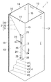
以上のように構成された第1実施形態の梱包具(1)は、縦長で平面視矩形状の大型製品を梱包するものである。すなわち図5に示すように、梱包製品の底面形状に対応した矩形状のパレット(6)上に、梱包製品が載置された状態で、梱包具(1)を梱包製品の上から被せるように配置して、梱包具(1)における前後左右の4側板部(11)〜(14)が、梱包製品における前後左右の4周側面を閉塞するように配置される。さらに梱包具(1)の上端開口部に、その上端開口部の形状に対応した矩形状の段ボール製蓋(5)が嵌合されて、その蓋(5)によって梱包具(1)の上端開口部が閉塞される。 The packaging tool (1) according to the first embodiment configured as described above is for packaging a large product that is vertically long and rectangular in plan view. That is, as shown in FIG. 5, the packaging tool (1) is placed on the packaged product with the packaged product placed on the rectangular pallet (6) corresponding to the bottom shape of the packaged product. It arrange | positions and it arrange | positions so that the 4 side board part (11)-(14) of front and rear, right and left in a packing tool (1) may block | close the front and rear, right and left four surrounding side surfaces in a packed product. Further, a rectangular corrugated cardboard lid (5) corresponding to the shape of the upper end opening is fitted into the upper end opening of the packing tool (1), and the upper end opening of the packing tool (1) is fitted by the lid (5). The part is blocked.
そしてその状態で、蓋(5)、右側板部(12)、パレット(6)および左側板部(13)の位置を通るように、複数のバンド(7)で縛り付け、これにより梱包が完了するものである。 And in that state, it is tied with a plurality of bands (7) so as to pass through the positions of the lid (5), the right side plate part (12), the pallet (6) and the left side plate part (13), thereby completing the packing. Is.
ここで、本実施形態の梱包具(1)においては、後側板部(13)がトラック等に積載する際の接地面(ずり降ろし面)として構成されており、荷揚げや荷卸しする際に、荷台に後側板部(13)を摺接させつつ、梱包具(1)を荷台に対して荷揚げしたり荷卸しするようにしている。 Here, in the packing tool (1) of the present embodiment, the rear plate portion (13) is configured as a ground surface (sliding down surface) when loading on a truck or the like, and when unloading or unloading, The packing tool (1) is unloaded from the loading platform or unloaded while the rear plate (13) is in sliding contact with the loading platform.
一方、上記したように製品を梱包した梱包具(1)を開梱する場合には、バンド(7)を取り除いた後、図2に示すように、作業者は上側開口部(21)を介して、切取許容部(23)の上端部を手で握って、手前に引っ張り込みながら下側に移動させていく。この外側への開き操作により、両側の切れ目線(24)(24)が、その上端を起点として、下方に向かって連続状に順次切り裂かれていき、切取許容部(23)が前側板部(11)から切り取られる。こうして図3に示すように、切取許容部(23)が開口されて、切り開き開始部(2)の全域が開口される。 On the other hand, when unpacking the packing tool (1) packed with the product as described above, after removing the band (7), as shown in FIG. 2, the operator passes through the upper opening (21). Then, grasp the upper end of the cut-off permission portion (23) with your hand and move it downward while pulling it toward you. By this outward opening operation, the cut lines (24) and (24) on both sides are successively torn downward continuously starting from the upper end, and the cut-off permitting portion (23) is moved to the front plate portion ( 11). In this way, as shown in FIG. 3, the cutting allowance portion (23) is opened, and the entire region of the cut opening start portion (2) is opened.
次に開口状態の切り開き開始部(2)を介して、切り開き領域(10)の右側縁部を手で握って、手前に引っ張り込みながら左側に移動させていく。この外側への開き操作により図4に示すように、上下両側切れ目線(3)(4)が、切り開き開始部(2)側の位置を起点にして、左側に向かって連続状に順次切り裂かれていき、前側板部(11)における切り開き領域(10)が残りの領域から切り離されて、前側板部(11)が周方向(左右方向)に分断される。 Next, the right edge of the slit region (10) is grasped with the hand through the slit opening start portion (2) in the open state, and moved to the left while being pulled forward. As shown in FIG. 4, the opening operation to the outside causes the upper and lower cut lines (3) and (4) to be successively cut toward the left starting from the position on the cut opening start portion (2) side. Then, the slit region (10) in the front plate portion (11) is cut off from the remaining region, and the front plate portion (11) is divided in the circumferential direction (left-right direction).
その後、各側板部(11)〜(14)を順次外側に開いていくように、梱包製品から離脱させることにより、梱包具(1)を梱包製品から完全に取り外すことができる。 Then, the packaging tool (1) can be completely removed from the packaged product by detaching it from the packaged product so that the side plate portions (11) to (14) are sequentially opened outward.
なお蓋(5)の取外操作や、梱包製品のパレット(6)からの降ろし操作等は、梱包具(1)を開梱する前に行っても良いし、開梱した後に行っても良い。 The operation for removing the lid (5) and the operation for unloading the packed product from the pallet (6) may be performed before unpacking the packing tool (1) or after unpacking. .
以上のように、第1実施形態の梱包具(1)によれば、梱包製品の周囲4面に配置される4枚の側板部(11)〜(14)のうちの前側板部(11)を、周方向に切り離すことができるように構成さている。このため、開梱時には、前側板部(11)を切り離して、周囲4枚の側板部(11)〜(14)を外側に開いていくだけで取り外すことができため、例えば梱包具を高く持ち上げて梱包製品から抜き取ったり、梱包具をカッターナイフ等で切り開いたりするような面倒な作業が必要なく、簡単かつスムーズに開梱することができる。 As mentioned above, according to the packing tool (1) of 1st Embodiment, the front side board part (11) of the four side board parts (11)-(14) arrange | positioned on the surrounding 4 surfaces of a packed product. Can be separated in the circumferential direction. For this reason, at the time of unpacking, the front side plate part (11) can be detached and the surrounding four side plate parts (11) to (14) can be removed simply by opening them outward. There is no need for the troublesome work of pulling out from the packaged product or opening the packing tool with a cutter knife or the like, and the unpacking can be performed easily and smoothly.
さらに本実施形態においては、前側板部(11)の切り開き領域(10)を横方向(左方向)に開いていくことにより、前側板部(11)を切り離すことができるため、作業者は手を横方向に移動させて、切り開き領域(10)を切り開くという無理のない簡単な操作で確実に開梱することができる。 Furthermore, in this embodiment, since the front side plate part (11) can be separated by opening the cut region (10) of the front side plate part (11) in the lateral direction (left direction), the operator can Can be unpacked reliably by a simple operation without unreasonableness.
また本実施形態においては、上下両側切れ目線(3)(4)に、高さ方向に平行な高さ方向直線部(32)(42)(44)を設けているため、前側板部(11)の高さ寸法が、左右方向(幅方向)寸法よりも極端に大きい場合、つまり前側板部(11)が背の高い大型製品に対応する形状であっても、上側切れ目線(3)を、切り開き開始部(2)から前側板部(11)の上端縁まで確実に形成できるとともに、下側切れ目線(4)を、切り開き開始部(2)から前側板部(11)の下端縁まで確実に形成することができる。従って梱包具(1)が、背の高い大型製品に対応する構成であっても、上下両側切れ目線(3)(4)を確実に形成できて、容易に開梱できるという上記と同様の効果を確実に得ることができる。 Moreover, in this embodiment, since the height direction linear part (32) (42) (44) parallel to a height direction is provided in the up-and-down both sides cut line (3) (4), the front side board part (11 ) Is extremely larger than the left-right direction (width direction) dimension, that is, even if the front plate (11) has a shape corresponding to a tall large product, the upper cut line (3) In addition, it can be reliably formed from the slit opening start portion (2) to the upper edge of the front plate portion (11), and the lower cut line (4) is formed from the slit opening portion (2) to the lower edge of the front plate portion (11). It can be reliably formed. Therefore, even if the packing tool (1) has a configuration corresponding to a tall large product, the same effect as described above that the upper and lower cut lines (3) and (4) can be reliably formed and can be easily unpacked. Can be definitely obtained.
さらに本実施形態においては、上側切れ目線(3)の高さ方向直線部(32)を、下側切れ目線(4)の高さ方向直線部(42)(44)に対し周方向に位置をずらせて配置しているため、強度を十分に確保することができる。すなわち仮に、上側切れ目線(3)の高さ方向直線部と、下側切れ目線(4)の高さ方向直線部とが一致して直線上に配置されていると、その部分は、切れ目線が上下に直列に配置されることとなり、折れ曲がり易くなって強度が低下するおそれがある。このため例えば梱包時にバンド(6)を巻き付けた際に、折れ曲がって外側に膨らんでしまうような不具合が発生する。そこで本実施形態では、高さ方向直線部(32)(42)(44)の位置を左右方向(周方向)にずらせているため、切れ目線が高さ方向に沿って広範囲に配置されるのを防止でき、不用意に折れ曲がるのを防止することができる。 Furthermore, in the present embodiment, the height direction straight line portion (32) of the upper cut line (3) is positioned in the circumferential direction with respect to the height direction straight line portions (42) and (44) of the lower cut line (4). Since the arrangement is shifted, sufficient strength can be ensured. That is, if the straight line in the height direction of the upper cut line (3) and the straight line in the height direction of the lower cut line (4) are arranged on a straight line, the portion is Are arranged in series in the vertical direction, and it is easy to bend and the strength may be lowered. For this reason, when winding a band (6) at the time of packing, for example, the malfunction which bends and bulges outside will generate | occur | produce. Therefore, in the present embodiment, since the positions of the height direction straight portions (32), (42), and (44) are shifted in the left and right direction (circumferential direction), the cut line is arranged in a wide range along the height direction. And can be prevented from being bent carelessly.
また本実施形態においては、切り開き開始部(2)を上下2つの開口部(21)(22)と、その開口部(21)(22)間に設けられた切取可能な切取許容部(23)とで構成しているため、開梱時には、切取許容部(23)を切り取って開口させることにより、開口寸法を縦長に大きく形成することができる。このように切り開き開始部(2)の開口寸法を長くできる分、上側切れ目線(3)および下側切れ目線(4)の長さを短くできて、切り開き量を少なくすることができ、開梱作業をより簡単に行うことができる。さらに切り開き開始部(2)の開口寸法が大きいため、適切な位置で切り開き領域(10)を把持して切り開くことができ、より一層スムーズに、切り開き操作を行うことができる。 In the present embodiment, the opening start portion (2) is divided into two upper and lower openings (21) and (22), and a cut-off allowable section (23) provided between the openings (21) and (22). Therefore, at the time of unpacking, the cut dimension (23) can be cut and opened to make the opening dimension large and long. Thus, the length of the upper cut line (3) and the lower cut line (4) can be shortened by the amount that the opening size of the cut opening start portion (2) can be increased, and the amount of the cut can be reduced, and unpacking can be performed. Work can be done more easily. Furthermore, since the opening dimension of the slit opening start portion (2) is large, the slit region (10) can be gripped and opened at an appropriate position, and the slit opening operation can be performed more smoothly.
また本実施形態においては、切取許容部(23)にその長さ方向に沿って等間隔おきに折り曲げ線(25)を形成しているため、既述したように、切取許容部(23)を段目方向に切り取って行く際に、切取許容部(23)が無理なく外側に折れ曲がっていき、切取許容部(23)を簡単かつスムーズに切り取ることができる。 In the present embodiment, since the folding lines (25) are formed at equal intervals along the length direction of the cutting allowance portion (23), as described above, the cutting allowance portion (23) is provided. When cutting in the step direction, the cutting allowance portion (23) bends outward without difficulty, and the cutting allowance portion (23) can be cut easily and smoothly.
また本実施形態においては、切り開き領域(10)が形成される前側板部(11)を、左側板部(14)に継ぎ合わせて角筒状に形成するようにしているため、強度の高い面を残存できて、全体として強度の低下を防止することができる。すなわち継ぎ合わされた2枚の側板部(11)(14)は、継ぎ合わせ加工によって段ボール構造の一部が破壊されてしまい、継ぎ合わされない側板部(12)(13)に比べて強度が低下してしまうことがあり、さらに前側板部(11)は、切り開き用に多数の切れ目線(24)(3)(4)が形成されるため、強度が低下してしまう。このため仮に、継ぎ合わされていない右側板部(12)または後板部(13)に、切り開き用の多数の切れ目線を形成すると、その側板部まで強度が低下してしまい、4枚の側板部のうち3枚の側板部の強度が低下してまう。換言すれば、高い強度の側板部が1枚のみになってしまい、全体として強度が低下するおそれがある。これに対し、本実施形態では、継ぎ合わされた側板部(11)に切り開き用に多数の切れ目線(24)(3)(4)を形成しているため、4枚の側板部のうち2枚の側板部(11)(14)の強度が低下してしまうだけで、残り2枚の側板部(12)(13)の強度を高く維持することができ、全体として強度低下を防止することができる。 Moreover, in this embodiment, since the front side plate part (11) in which the cut area (10) is formed is joined to the left side plate part (14) to form a rectangular tube, a high strength surface. As a whole, a decrease in strength can be prevented. That is, the two side plate portions (11) and (14) that are joined together have a portion of the corrugated cardboard structure destroyed by the joining process, and the strength is lower than the side plate portions (12) and (13) that are not joined together. Further, the front side plate portion (11) is formed with a large number of cut lines (24), (3), and (4) for slitting, resulting in a decrease in strength. For this reason, if a large number of slit lines are formed in the right side plate portion (12) or the rear plate portion (13) that are not joined, the strength decreases to the side plate portion, and the four side plate portions Among them, the strength of the three side plate portions will decrease. In other words, there is only one high-strength side plate portion, which may reduce the strength as a whole. On the other hand, in this embodiment, since many cut lines (24), (3), and (4) are formed for slitting in the joined side plate portions (11), two of the four side plate portions are formed. The strength of the remaining two side plate portions (12) and (13) can be maintained high only by reducing the strength of the side plate portions (11) and (14), and the strength can be prevented from decreasing as a whole. it can.
その上さらに、本実施形態においては、高い強度の後側板部(13)を、トラック荷台に対し積み卸しする際等のずり降ろし面(接地面)として構成しているため、積み卸し時に、後側板部(13)をトラック荷台に強く摺接させようとも、後側板部(13)が損傷するのを有効に防止できて、積み卸し作業等を効率良くスムーズに行うことができる。 In addition, in the present embodiment, the high-strength rear side plate (13) is configured as a sliding surface (grounding surface) when unloading from the truck bed, so Even if the side plate portion (13) is slidably brought into sliding contact with the truck bed, it is possible to effectively prevent the rear side plate portion (13) from being damaged, and the loading and unloading work can be performed efficiently and smoothly.
特に本実施形態においては、梱包時にバンド(6)を左右側板部(12)(14)に配置しているため、バンド(6)が、ずり降ろし面としての後側板部(13)に配置されることがない。このため、後側板部(13)を荷台に摺接したさせた際に、バンド(6)がすり切れてしまうような不具合を防止することができる。 In particular, in this embodiment, since the band (6) is disposed on the left and right side plate portions (12) and (14) during packaging, the band (6) is disposed on the rear plate portion (13) as a sliding surface. There is nothing to do. For this reason, when the rear side plate portion (13) is brought into sliding contact with the loading platform, it is possible to prevent a problem that the band (6) is worn out.
また、前側板部(11)の上端縁における上側切れ目線(3)の上端位置や、前側板部(11)の下端縁における下側切れ目線(4)の下端位置は、折れ曲がり易くなっているが、本実施形態においては、上側切れ目線(3)の上端位置および下側切れ目線(4)の下端位置を、前側板部(11)および左側板部(14)間のコーナ部、つまり段ボールを折り曲げる位置に配置している。このため、切れ目線(3)(4)の端部位置が折れ曲がり易くとも何ら問題はなく、むしろ側板部間を無理なく折り曲げることができ、梱包具(1)の製作作業を容易に行うことができる。 Further, the upper end position of the upper cut line (3) at the upper end edge of the front plate part (11) and the lower end position of the lower cut line (4) at the lower end edge of the front plate part (11) are easily bent. However, in this embodiment, the upper end position of the upper cut line (3) and the lower end position of the lower cut line (4) are set to a corner portion between the front plate portion (11) and the left plate portion (14), that is, corrugated cardboard. Is placed in a position to bend. For this reason, there is no problem even if the end positions of the cut lines (3) and (4) are easy to bend. Rather, the side plate portions can be bent without difficulty, and the packaging tool (1) can be easily manufactured. it can.
さらに本実施形態においては、前側板部(11)の上端縁に達する上側切れ目線(3)の第3直線部(33)を斜め方向に配置して、上側切れ目線(3)が前側板部(11)の上端縁から斜め方向に切り込まれるようにしているため、十分な強度を確実に得ることができる。すなわち上側切れ目線(3)が前側板部(11)の上端縁から高さ方向(垂直方向)に直線的に切り込まれる場合には、その切込部において折れ曲がり易くなってしまうが、本実施形態では、上側切れ目線(3)が前側板部(11)の上端縁から斜め方向に切り込まれるようにしているため、その切込部が折れ曲がり難く、十分な強度を確実に得ることができる。 Furthermore, in this embodiment, the 3rd straight part (33) of the upper side cut line (3) which reaches the upper end edge of the front side board part (11) is arrange | positioned diagonally, and an upper side cut line (3) is a front side board part. Since it is cut in the oblique direction from the upper edge of (11), sufficient strength can be obtained with certainty. That is, when the upper cut line (3) is linearly cut in the height direction (vertical direction) from the upper end edge of the front plate part (11), it is easy to bend at the cut part. In the embodiment, since the upper cut line (3) is cut obliquely from the upper end edge of the front plate part (11), the cut part is not easily bent and sufficient strength can be obtained with certainty. .
同様に、前側板部(11)の下端縁に達する下側切れ目線(3)の第5直線部(45)を斜め方向に配置して、下側切れ目線(3)が前側板部(11)の下端縁から斜め方向に切り込まれるように配置しているため、下側切れ目線(3)が前側板部(11)の下端縁から縦方向に直線的に切り込まれる場合と比較して、折れ曲がり難く、十分な強度をより確実に得ることができる。 Similarly, the fifth straight portion (45) of the lower cut line (3) reaching the lower end edge of the front plate portion (11) is arranged in an oblique direction, and the lower cut line (3) is moved to the front plate portion (11). The lower cut line (3) is linearly cut in the vertical direction from the lower edge of the front plate portion (11). Therefore, it is difficult to bend and sufficient strength can be obtained more reliably.
また本実施形態の梱包具(1)は、側板部(11)〜(14)が、2層構造の強化段ボールによって構成されているため、側板部(11)〜(14)そのものの強度が向上し、ひいては梱包具全体の強度をより一層向上させることができる。 Moreover, since the side plate part (11)-(14) is comprised by the reinforced corrugated cardboard of 2 layer structure, the intensity | strength of side plate part (11)-(14) itself improves the packing tool (1) of this embodiment. As a result, the strength of the entire packaging tool can be further improved.
<第2実施形態>
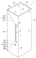
図7はこの発明の第2実施形態である段ボール製梱包具(1a)を示す展開図である。同図に示すようにこの梱包具(1a)は、前側板部(11)における上側切れ目線(3a)が、下側から順に配置される第1および第2の2本の直線部(31a)(32a)によって構成されている。
<Second Embodiment>
FIG. 7 is a developed view showing a corrugated cardboard packaging tool (1a) according to a second embodiment of the present invention. As shown in the figure, the packing device (1a) includes a first straight line portion (31a) and a second straight line portion (31a) in which the upper cut line (3a) in the front plate portion (11) is arranged in order from the lower side. (32a).
第1直線部(31a)は、高さ方向に対し平行な方向に直進する高さ方向直線部として構成されており、下端が上側開口部(21)に達するように配置されている。 The first straight portion (31a) is configured as a height-direction straight portion that goes straight in a direction parallel to the height direction, and is arranged so that the lower end reaches the upper opening (21).
第2直線部(32a)は、高さ方向に対し45°で傾斜する方向に直進する斜め方向直線部として構成されており、下端が第1直線部(31a)の上端に接続されるとともに、上端が、前側板部(11)における上端縁のやや左寄り位置に達するように配置されている。 The second straight portion (32a) is configured as an oblique straight portion that goes straight in a direction inclined at 45 ° with respect to the height direction, the lower end is connected to the upper end of the first straight portion (31a), and The upper end is arranged so as to reach a position slightly to the left of the upper end edge of the front plate part (11).
さらに本第2実施形態の梱包具(1a)では、上記第1実施形態の梱包具(1)に比べて、前側板部(11)における切り開き開始部(2)の上下方向長さが短く設定されている。 Furthermore, in the packing tool (1a) of the second embodiment, the length in the vertical direction of the slit opening start portion (2) in the front plate (11) is set shorter than that of the packing tool (1) of the first embodiment. Has been.
本第2実施形態の梱包具(1a)において他の構成は、上記第1実施形態と実質的に同様であるため、同一または相当部分に、同一または相当符号を付して、重複説明は省略する。 In the packaging device (1a) of the second embodiment, since the other configuration is substantially the same as that of the first embodiment, the same or corresponding parts are denoted by the same or corresponding reference numerals, and redundant description is omitted. To do.
この第2実施形態の梱包具(1a)においても、上記第1実施形態と同様に、同様の作用効果を得ることができる。 Also in the packing tool (1a) of this 2nd Embodiment, the same effect can be obtained similarly to the said 1st Embodiment.
<変形例>
上記実施形態においては、切れ目線(破断誘導線)を、端部が曲成した短寸の切込が多数、線上に並んで配置されたジッパー状に形成しているが、それだけに限られず、本発明においては、切れ目線の形状は特に限定されるものではない。例えば、切れ目線(破断誘導線)を、直線形状の短寸の切込が多数、線上に直列に並んで配置されたミシン目状に形成しても良いし、針孔状の孔が多数、線上に並んで配置された構成に形成するようにしても良い。
<Modification>
In the above-described embodiment, the cut line (breaking guide line) is formed in a zipper shape in which a large number of short cuts with curved ends are arranged side by side on the line. In the invention, the shape of the cut line is not particularly limited. For example, the cut line (breaking induction line) may be formed in the form of perforations arranged in series on the line with a large number of short cuts in a linear shape, or a large number of needle hole-like holes, You may make it form in the structure arrange | positioned along with the line.
また上記実施形態においては、切り開き開始部(2)を開口部(21)(22)と、切取許容部(23)とで構成し、開梱時には切取許容部(23)を切り取って、開口部(21)(22)と共に、全域を開口させるようにしているが、それだけに限られず、本発明において、切り開き開始部は、少なくとも開梱操作開始以降(開梱時)に開口されている部分によって構成されていれば良く、換言すれば開口した部分および開口できる部分の少なくともいずれか一方によって構成すれば良い。ここで、開口した部分とは、梱包操作前に開口している部分であり、上記実施形態の開口部(21)(22)等に相当する。開口できる部分とは、梱包操作前には閉塞されているが、開梱開始時以降には所定の操作を行うことによって開口される部分であって、上記実施形態の切取許容部(23)等に相当する。それ以外に開口できる部分とは、コ字状やL字状に切り込まれた部分であって、開梱時には、押し曲げたり、引き曲げたりして開口できる部分等によって構成することができる。言うまでもなく、切り開き開始部は、開口した部分だけで構成するようにしても良いし、開口できる部分だけで構成するようにしても良いし、開口した部分と、開口できる部分とを組み合わせて構成するようにしても良い。 Further, in the above embodiment, the opening start portion (2) is composed of the openings (21) and (22) and the cutting allowance portion (23), and the uncut opening portion (23) is cut off at the time of unpacking. (21) The whole area is opened together with (22). However, the present invention is not limited to this, and in the present invention, the opening start portion is constituted by a portion opened at least after the opening operation is started (when unpacking). In other words, what is necessary is just to comprise at least any one of the part opened and the part which can be opened. Here, the opened part is a part opened before the packing operation, and corresponds to the openings (21), (22) and the like in the above embodiment. The portion that can be opened is a portion that is closed before the packing operation, but is opened by performing a predetermined operation after the start of unpacking, such as the cut-off permissible portion (23) in the above embodiment. It corresponds to. The portion that can be opened other than that is a portion that is cut into a U-shape or an L-shape, and can be configured by a portion that can be opened by being pushed or bent when unpacking. Needless to say, the slit opening start portion may be configured by only the opened portion, may be configured by only the portion that can be opened, or may be configured by combining the opened portion and the portion that can be opened. You may do it.
また上記実施形態においては、上下両側破断誘導線としての切れ目線(3)(4)を、複数の直線部によって構成するようにしているが、それだけに限られず、本発明においては、各破断誘導線を1本の直線部によって構成しても良いし、破断誘導線に、緩やかに曲成した曲線部を含めるようにしても良い。曲線部を含める場合、破断誘導線を1本の曲線部によって構成しても良いし、曲率の異なる複数の曲線部によって構成するようにしても良いし、1〜複数の曲線部と、1〜複数の直線部とを組み合せて構成するようにしても良い。 Further, in the above embodiment, the cut lines (3) and (4) as the upper and lower both-side break guide lines are configured by a plurality of straight portions, but the present invention is not limited thereto, and in the present invention, each break guide line is May be configured by a single straight line portion, or a gently curved curve portion may be included in the break guide line. When including a curved portion, the breakage guide line may be constituted by a single curved portion, or may be constituted by a plurality of curved portions having different curvatures, or 1 to a plurality of curved portions, and 1 to You may make it comprise combining a some linear part.
また上記実施形態においては、説明の都合上、前側板部(11)を、開梱時に切り裂かれる開梱用側板部として構成するようにしているが、それだけに限られず、本発明において、開梱用側板部が配置される位置は限定されるものではなく、周囲に配置される側板部であればいずれの側板部も、開梱用側板部に構成することができる。 In the above embodiment, for convenience of explanation, the front side plate portion (11) is configured as a side plate portion for unpacking that is torn during unpacking. However, the present invention is not limited to this, and in the present invention, for unpacking. The position where the side plate portion is arranged is not limited, and any side plate portion can be configured as the unpacking side plate portion as long as it is a side plate portion arranged around.
さらに上記実施形態においては、4枚の側板部が周方向に連設されて、周囲4面にそれぞれ側板部が設けられた梱包具に、本発明を適用した場合を例に挙げて説明したが、それだけに限られず、本発明は、3枚、あるいは5枚以上の側板部が周方向に連設された梱包具にも適用することができる。もっとも本発明は、形態安定性等を考慮すると、上記実施形のように、4枚の側板部によって周囲4面が閉塞される形態の梱包具に適用するのが好ましい。
Furthermore, in the said embodiment, although the side plate part of 4 sheets was connected in the circumferential direction, it demonstrated as an example the case where this invention was applied to the packaging tool by which the side plate part was each provided in the surrounding 4 surface. However, the present invention is not limited thereto, and the present invention can also be applied to a packaging tool in which three or five or more side plate portions are continuously provided in the circumferential direction. However, in consideration of form stability and the like, the present invention is preferably applied to a packing tool in a form in which the surrounding four surfaces are closed by four side plate portions as in the above embodiment.
この発明の段ボール製梱包具は、製品の搬送や保管時に製品を梱包するのに利用することができる。 The corrugated cardboard packing tool of the present invention can be used for packing a product when the product is transported or stored.
1,1a…梱包具
11〜14…側板部
2…切り開き開始部
21,22…開口部
23…切取許容部
24…中間切れ目線(中間破断誘導線)
25…折り曲げ線
3…上側破断誘導線
31,32a,45…直線部(斜め方向直線部)
31a,32,42,44…直線部(高さ方向直線部)
DESCRIPTION OF
25 ... bending
31a, 32, 42, 44 ... straight part (height direction straight part)
Claims (10)
前記複数の側板部のうちいずれか1つの側板部が、開梱用側板部として構成され、
前記開梱用側板部に、高さ方向中間部における周方向一方寄りの位置に、開梱時に開口されている切り開き開始部が設けられ、
前記開梱用側板部に、その上端縁の周方向他方寄りの位置から、前記切り開き開始部の上端にかけて斜め方向に沿って上側破断誘導線が設けられるとともに、
前記開梱用側板部に、その下端縁の周方向他方寄りの位置から、前記切り開き開始部の下端にかけて斜め方向に沿って下側破断誘導線が設けられ、
前記上下両側破断誘導線および前記切り開き開始部を境界線にして、前記開梱用側板部が周方向に区分けされて、その他方側の領域が切り開き領域として構成され、
開口された状態の前記切り開き開始部に対応する部分を起点にして、前記切り開き領域が外側に開き操作されることにより、前記開梱用側板部が前記上下両側破断誘導線に沿って破断されて周方向に切り離されるように構成されたことを特徴とする段ボール製梱包具。 Three or more side plate portions are continuously provided in the circumferential direction so that the periphery of the packaged product can be closed, and each side plate portion is configured by corrugated cardboard with the step direction corresponding to the height direction of the packaged product. A cardboard packaging tool,
Any one side plate portion of the plurality of side plate portions is configured as an unpacking side plate portion,
The unpacking side plate is provided with a slit opening start portion opened at the time of unpacking at a position closer to one side in the circumferential direction in the intermediate portion in the height direction,
On the unpacking side plate part, an upper fracture guide line is provided along an oblique direction from a position near the other end in the circumferential direction of the upper end edge to the upper end of the slit opening start part,
On the unpacking side plate portion, a lower break guide line is provided along a diagonal direction from a position closer to the other end in the circumferential direction of the lower end edge to a lower end of the slit opening start portion,
The unwrapping side plate is divided in the circumferential direction with the upper and lower side breakage guide lines and the cut start part as a boundary line, and the other side area is configured as a cut area,
Starting from a portion corresponding to the opening start portion in the opened state, the opening region is opened outwardly, whereby the unpacking side plate portion is broken along the upper and lower both-side break guide lines. A corrugated cardboard packaging tool configured to be cut off in the circumferential direction.
前記切取許容部は、高さ方向に延びる縦長帯状に形成されるとともに、その切取許容部の両側縁に沿って中間破断誘導線が設けられ、
前記切取許容部は、その上下両端のいずれか一方を起点にして、外側に引張操作されることにより、切り取られるように構成され、
前記切取許容部に、周方向に延びる折れ曲げ線が、高さ方向に間隔をおいて複数設けられる請求項1〜8のいずれか1項に記載の段ボール製梱包具。 The cut opening start portion is provided at least in part with a cutting allowance portion that can be opened by a cutting operation,
The cut-off permission portion is formed in a vertically long strip shape extending in the height direction, and an intermediate break guide line is provided along both side edges of the cut-off permission portion,
The cutting allowance portion is configured to be cut by being pulled outward from either one of its upper and lower ends,
The corrugated cardboard packaging tool according to any one of claims 1 to 8, wherein a plurality of bending lines extending in the circumferential direction are provided at intervals in the height direction in the cut-off permission portion.
Priority Applications (1)
| Application Number | Priority Date | Filing Date | Title |
|---|---|---|---|
| JP2008230424A JP5399667B2 (en) | 2008-09-09 | 2008-09-09 | Cardboard packaging |
Applications Claiming Priority (1)
| Application Number | Priority Date | Filing Date | Title |
|---|---|---|---|
| JP2008230424A JP5399667B2 (en) | 2008-09-09 | 2008-09-09 | Cardboard packaging |
Publications (2)
| Publication Number | Publication Date |
|---|---|
| JP2010064756A true JP2010064756A (en) | 2010-03-25 |
| JP5399667B2 JP5399667B2 (en) | 2014-01-29 |
Family
ID=42190694
Family Applications (1)
| Application Number | Title | Priority Date | Filing Date |
|---|---|---|---|
| JP2008230424A Active JP5399667B2 (en) | 2008-09-09 | 2008-09-09 | Cardboard packaging |
Country Status (1)
| Country | Link |
|---|---|
| JP (1) | JP5399667B2 (en) |
Cited By (6)
| Publication number | Priority date | Publication date | Assignee | Title |
|---|---|---|---|---|
| JP2013180801A (en) * | 2012-03-01 | 2013-09-12 | Corona Corp | Packing material |
| JP2013180799A (en) * | 2012-03-01 | 2013-09-12 | Corona Corp | Packaging material |
| JP2014019475A (en) * | 2012-07-19 | 2014-02-03 | Sigma Shigyo Kk | Paper can container |
| JP2014213874A (en) * | 2013-04-24 | 2014-11-17 | 三菱電機株式会社 | Hot water storage water heater packaging member |
| JP5948463B1 (en) * | 2015-05-29 | 2016-07-06 | 大王パッケージ株式会社 | Box sheet |
| JP7283113B2 (en) | 2019-02-21 | 2023-05-30 | 京セラドキュメントソリューションズ株式会社 | Ink container and ink container package |
Citations (7)
| Publication number | Priority date | Publication date | Assignee | Title |
|---|---|---|---|---|
| US3357631A (en) * | 1963-12-03 | 1967-12-12 | Continental Can Co | Recessed ice-cream carton with tuck-in reclosure |
| FR2041659A5 (en) * | 1969-05-19 | 1971-01-29 | Micomat | |
| JPS563822U (en) * | 1979-06-22 | 1981-01-14 | ||
| JPS573660U (en) * | 1980-06-10 | 1982-01-09 | ||
| JPH0922092A (en) * | 1995-07-06 | 1997-01-21 | Fuji Photo Film Co Ltd | Package of film product |
| JP2003502220A (en) * | 1999-06-15 | 2003-01-21 | オトール | Cardboard case and blank with tear wall |
| JP2007284082A (en) * | 2006-04-13 | 2007-11-01 | Konica Minolta Business Technologies Inc | Packing box, packing method, and unpacking method |
-
2008
- 2008-09-09 JP JP2008230424A patent/JP5399667B2/en active Active
Patent Citations (7)
| Publication number | Priority date | Publication date | Assignee | Title |
|---|---|---|---|---|
| US3357631A (en) * | 1963-12-03 | 1967-12-12 | Continental Can Co | Recessed ice-cream carton with tuck-in reclosure |
| FR2041659A5 (en) * | 1969-05-19 | 1971-01-29 | Micomat | |
| JPS563822U (en) * | 1979-06-22 | 1981-01-14 | ||
| JPS573660U (en) * | 1980-06-10 | 1982-01-09 | ||
| JPH0922092A (en) * | 1995-07-06 | 1997-01-21 | Fuji Photo Film Co Ltd | Package of film product |
| JP2003502220A (en) * | 1999-06-15 | 2003-01-21 | オトール | Cardboard case and blank with tear wall |
| JP2007284082A (en) * | 2006-04-13 | 2007-11-01 | Konica Minolta Business Technologies Inc | Packing box, packing method, and unpacking method |
Cited By (6)
| Publication number | Priority date | Publication date | Assignee | Title |
|---|---|---|---|---|
| JP2013180801A (en) * | 2012-03-01 | 2013-09-12 | Corona Corp | Packing material |
| JP2013180799A (en) * | 2012-03-01 | 2013-09-12 | Corona Corp | Packaging material |
| JP2014019475A (en) * | 2012-07-19 | 2014-02-03 | Sigma Shigyo Kk | Paper can container |
| JP2014213874A (en) * | 2013-04-24 | 2014-11-17 | 三菱電機株式会社 | Hot water storage water heater packaging member |
| JP5948463B1 (en) * | 2015-05-29 | 2016-07-06 | 大王パッケージ株式会社 | Box sheet |
| JP7283113B2 (en) | 2019-02-21 | 2023-05-30 | 京セラドキュメントソリューションズ株式会社 | Ink container and ink container package |
Also Published As
| Publication number | Publication date |
|---|---|
| JP5399667B2 (en) | 2014-01-29 |
Similar Documents
| Publication | Publication Date | Title |
|---|---|---|
| JP5399667B2 (en) | Cardboard packaging | |
| JP6276784B2 (en) | Package that can be easily torn | |
| EP3186155B1 (en) | Carton configured with dual opening capabilities | |
| CN108349637B (en) | Bag-type wrapper and associated method for adapting such wrapper | |
| JP6035000B2 (en) | Packing display box | |
| JP2006111342A (en) | Easily openable paper case | |
| WO2012060721A1 (en) | Improvements in and relating to packaging | |
| JP6536342B2 (en) | Box and box blank sheet | |
| JP2008100716A (en) | Food packaging material for sandwich or suchlike | |
| JP2018090292A (en) | Packaging box | |
| JP2008044664A (en) | Preventing corrugated cardboard from wounding hand | |
| JP6581534B2 (en) | Opened cardboard box | |
| JP5311224B2 (en) | Easy-open packaging bag | |
| JP5086168B2 (en) | Packaging display box | |
| JP6524141B2 (en) | Packaging box | |
| JP5220067B2 (en) | Cardboard box opening structure and die cutting with cutting blade forming the opening structure | |
| CN106660659A (en) | Packaging box and packaging box blank sheet | |
| JP6898068B2 (en) | Packaging bag | |
| JP2015003739A (en) | Shrink package | |
| JP2005212868A (en) | Package for flat object | |
| JP2019001474A (en) | Packing box and blank of packing box | |
| JP3230147U (en) | Packaging box and blank | |
| JP4298417B2 (en) | Packing display box | |
| JP7056252B2 (en) | Perforated structure and packaging | |
| JP2008162659A (en) | Packaging box |
Legal Events
| Date | Code | Title | Description |
|---|---|---|---|
| A621 | Written request for application examination |
Free format text: JAPANESE INTERMEDIATE CODE: A621 Effective date: 20110823 |
|
| A977 | Report on retrieval |
Free format text: JAPANESE INTERMEDIATE CODE: A971007 Effective date: 20121228 |
|
| A131 | Notification of reasons for refusal |
Free format text: JAPANESE INTERMEDIATE CODE: A131 Effective date: 20130115 |
|
| A521 | Request for written amendment filed |
Free format text: JAPANESE INTERMEDIATE CODE: A523 Effective date: 20130315 |
|
| TRDD | Decision of grant or rejection written | ||
| A01 | Written decision to grant a patent or to grant a registration (utility model) |
Free format text: JAPANESE INTERMEDIATE CODE: A01 Effective date: 20131001 |
|
| A61 | First payment of annual fees (during grant procedure) |
Free format text: JAPANESE INTERMEDIATE CODE: A61 Effective date: 20131024 |
|
| R150 | Certificate of patent or registration of utility model |
Ref document number: 5399667 Country of ref document: JP Free format text: JAPANESE INTERMEDIATE CODE: R150 Free format text: JAPANESE INTERMEDIATE CODE: R150 |
|
| RD02 | Notification of acceptance of power of attorney |
Free format text: JAPANESE INTERMEDIATE CODE: R3D02 |
|
| R250 | Receipt of annual fees |
Free format text: JAPANESE INTERMEDIATE CODE: R250 |
|
| R250 | Receipt of annual fees |
Free format text: JAPANESE INTERMEDIATE CODE: R250 |
|
| S531 | Written request for registration of change of domicile |
Free format text: JAPANESE INTERMEDIATE CODE: R313531 |
|
| R350 | Written notification of registration of transfer |
Free format text: JAPANESE INTERMEDIATE CODE: R350 |
|
| R250 | Receipt of annual fees |
Free format text: JAPANESE INTERMEDIATE CODE: R250 |