JP2010063644A - Blood purifying apparatus - Google Patents
Blood purifying apparatus Download PDFInfo
- Publication number
- JP2010063644A JP2010063644A JP2008232812A JP2008232812A JP2010063644A JP 2010063644 A JP2010063644 A JP 2010063644A JP 2008232812 A JP2008232812 A JP 2008232812A JP 2008232812 A JP2008232812 A JP 2008232812A JP 2010063644 A JP2010063644 A JP 2010063644A
- Authority
- JP
- Japan
- Prior art keywords
- blood
- index
- time
- detected
- appropriate range
- Prior art date
- Legal status (The legal status is an assumption and is not a legal conclusion. Google has not performed a legal analysis and makes no representation as to the accuracy of the status listed.)
- Granted
Links
- 210000004369 blood Anatomy 0.000 title claims abstract description 225
- 239000008280 blood Substances 0.000 title claims abstract description 225
- 238000012544 monitoring process Methods 0.000 claims abstract description 26
- 230000008859 change Effects 0.000 claims description 50
- 238000000746 purification Methods 0.000 claims description 31
- 238000001514 detection method Methods 0.000 claims description 28
- 230000004087 circulation Effects 0.000 claims description 2
- 230000002123 temporal effect Effects 0.000 abstract description 6
- 238000000502 dialysis Methods 0.000 description 37
- 238000011282 treatment Methods 0.000 description 37
- 238000005534 hematocrit Methods 0.000 description 28
- XLYOFNOQVPJJNP-UHFFFAOYSA-N water Substances O XLYOFNOQVPJJNP-UHFFFAOYSA-N 0.000 description 18
- 238000000034 method Methods 0.000 description 15
- 230000007423 decrease Effects 0.000 description 13
- 239000012510 hollow fiber Substances 0.000 description 10
- 230000007704 transition Effects 0.000 description 7
- 230000002093 peripheral effect Effects 0.000 description 6
- 210000001367 artery Anatomy 0.000 description 4
- 238000001631 haemodialysis Methods 0.000 description 4
- 230000000322 hemodialysis Effects 0.000 description 4
- 238000005259 measurement Methods 0.000 description 4
- 230000008569 process Effects 0.000 description 4
- 230000000630 rising effect Effects 0.000 description 4
- 206010040560 shock Diseases 0.000 description 4
- 239000000385 dialysis solution Substances 0.000 description 3
- 230000006870 function Effects 0.000 description 3
- 239000012528 membrane Substances 0.000 description 3
- 238000002560 therapeutic procedure Methods 0.000 description 3
- 239000002699 waste material Substances 0.000 description 3
- 206010021036 Hyponatraemia Diseases 0.000 description 2
- 208000034767 Hypoproteinaemia Diseases 0.000 description 2
- 208000001953 Hypotension Diseases 0.000 description 2
- 150000001875 compounds Chemical class 0.000 description 2
- 210000003743 erythrocyte Anatomy 0.000 description 2
- 230000036543 hypotension Effects 0.000 description 2
- 230000031700 light absorption Effects 0.000 description 2
- 230000007246 mechanism Effects 0.000 description 2
- 239000011148 porous material Substances 0.000 description 2
- 239000000047 product Substances 0.000 description 2
- 230000036962 time dependent Effects 0.000 description 2
- 210000003462 vein Anatomy 0.000 description 2
- 241001227124 Dialytes Species 0.000 description 1
- 102000001554 Hemoglobins Human genes 0.000 description 1
- 108010054147 Hemoglobins Proteins 0.000 description 1
- 238000010521 absorption reaction Methods 0.000 description 1
- 238000013459 approach Methods 0.000 description 1
- 210000000601 blood cell Anatomy 0.000 description 1
- 230000017531 blood circulation Effects 0.000 description 1
- 230000036772 blood pressure Effects 0.000 description 1
- 230000037396 body weight Effects 0.000 description 1
- 238000010586 diagram Methods 0.000 description 1
- 230000009977 dual effect Effects 0.000 description 1
- 238000001914 filtration Methods 0.000 description 1
- 238000002637 fluid replacement therapy Methods 0.000 description 1
- 230000012447 hatching Effects 0.000 description 1
- 230000036541 health Effects 0.000 description 1
- 238000002615 hemofiltration Methods 0.000 description 1
- 239000007788 liquid Substances 0.000 description 1
- 238000012423 maintenance Methods 0.000 description 1
- 238000012806 monitoring device Methods 0.000 description 1
- 230000003287 optical effect Effects 0.000 description 1
- 230000000149 penetrating effect Effects 0.000 description 1
- 239000012466 permeate Substances 0.000 description 1
- 210000002381 plasma Anatomy 0.000 description 1
- 102000004169 proteins and genes Human genes 0.000 description 1
- 108090000623 proteins and genes Proteins 0.000 description 1
- 210000002966 serum Anatomy 0.000 description 1
- 230000002792 vascular Effects 0.000 description 1
Images


Abstract
Description
本発明は、患者の血液を体外循環させつつ浄化する血液浄化装置に関するものである。 The present invention relates to a blood purification apparatus for purifying a patient's blood while circulating it outside the body.
一般に、血液浄化療法、例えば透析治療においては、患者の血液を体外循環させるべく可撓性チューブから成る血液回路が使用されている。この血液回路は、患者から血液を採取する動脈側穿刺針が先端に取り付けられた動脈側血液回路と、患者に血液を戻す静脈側穿刺針が先端に取り付けられた静脈側血液回路とから主に成り、これら動脈側血液回路と静脈側血液回路との間に血液浄化手段(ダイアライザ)を介在させ、体外循環する血液の浄化を行っている。 In general, in blood purification therapy such as dialysis treatment, a blood circuit composed of a flexible tube is used to circulate a patient's blood extracorporeally. This blood circuit is mainly composed of an arterial blood circuit in which an arterial puncture needle for collecting blood from a patient is attached to the tip, and a venous blood circuit in which a venous puncture needle for returning blood to the patient is attached to the tip. The blood purification means (dialyzer) is interposed between the arterial blood circuit and the venous blood circuit to purify blood circulating outside the body.
かかるダイアライザは、内部に複数の中空糸が配設されており、それぞれの中空糸の内部を血液が通過するとともに、その外側(中空糸の外周面と筐体の内周面との間)に透析液を流し得る構成とされている。中空糸は、その壁面に微小な孔(ポア)が形成されて血液浄化膜を成しており、中空糸内部を通過する血液の老廃物等が血液浄化膜を透過して透析液内に排出されるとともに、老廃物が排出されて浄化された血液が患者の体内に戻るようになっている。また、透析装置内には、患者の血液から水分を取り除くための除水ポンプが配設されており、透析治療時に除水が行われるように構成されている。 In such a dialyzer, a plurality of hollow fibers are arranged inside, and blood passes through the inside of each hollow fiber, and on the outside thereof (between the outer peripheral surface of the hollow fiber and the inner peripheral surface of the housing). It is set as the structure which can flow a dialysate. The hollow fiber has a blood purification membrane with micropores (pores) formed in the wall surface, and waste products of blood passing through the hollow fiber permeate the blood purification membrane and are discharged into the dialysate. At the same time, waste blood is discharged and purified blood returns to the patient's body. In the dialysis machine, a water removal pump for removing water from the patient's blood is disposed, and water removal is performed during dialysis treatment.
然るに、除水すべき量(水分除去量)が多い場合、除水速度を高くする必要があるため、患者の健康状態によっては、しばしば低血圧などのショック症状を引き起こす可能性がある。かかるショック症状の前兆を把握すべく、従来、透析治療中における患者の血液のヘマトクリット値(血液中の血球成分の体積分率)を検出し、このヘマトクリット値から患者の循環血液量の変化率(ΔBV%)を算出して監視する装置が提案されている。 However, when the amount of water to be removed (water removal amount) is large, it is necessary to increase the rate of water removal. Therefore, depending on the health condition of the patient, shock symptoms such as hypotension can often be caused. Conventionally, in order to grasp the signs of such shock symptoms, the hematocrit value of the patient's blood during dialysis treatment (volume fraction of blood cell components in the blood) is detected, and the change rate of the patient's circulating blood volume from this hematocrit value ( An apparatus for calculating and monitoring (ΔBV%) has been proposed.
即ち、通常、除水によって患者の循環血液量の変化率(ΔBV%)は治療時間の経過に伴い低下するのであるが、急激なΔBV%の低下が生じた場合には低血圧などのショック症状が生じる前兆であると予想され、当該急激なΔBV%の低下時に何らかの処置(補液処置や透析治療の停止等)を施せばショック症状を未然に防止することが可能と考えられるのである。而して、透析治療中において、患者のヘマトクリット値を逐次測定し、そのヘマトクリット値から患者の循環血液量の変化率(ΔBV%)を検出し得る透析治療装置が例えば特許文献1にて開示されている。
然るに、比較的長期に亘って透析治療を行っている安定維持透析患者においては、通常、循環血液量変化率ΔBV%の如き透析治療過程で体外循環する血液の濃度に係るパラメータを時系列的に複数時点で測定することにより得られた時系列データ(特に標準化したもの)については、再現性があることが分かっている。しかして、本出願人は、時系列データの再現性を利用することにより、透析治療過程における透析治療の適否をリアルタイムに把握することができる血液透析装置を検討するに至った。 However, in stable maintenance dialysis patients who have been undergoing dialysis treatment for a relatively long period of time, parameters such as the blood volume change rate ΔBV%, which are related to the concentration of blood circulating extracorporeally in the course of dialysis treatment, are usually measured in time series. It has been found that time series data (particularly standardized) obtained by measuring at a plurality of time points has reproducibility. Thus, the present applicant has studied a hemodialysis apparatus that can grasp in real time whether or not dialysis treatment is appropriate in the dialysis treatment process by using the reproducibility of time series data.
しかしながら、その場合、治療開始直後(これを「立上がり時間」と呼ぶ)においては、バスキュラーアクセス再循環や低ナトリウム血症、低蛋白血症など患者固有の事情、或いは立位から臥位への体位変更に伴う水分の移動など治療状態の事情により、ヘマトクリット値などの検出される血液指標が不安定な場合があり、その場合、再現性がなくなってしまうという不具合があった。このように、検出される血液指標が不安定である場合は、適切な適正範囲を設定することが困難となってしまう。 However, in that case, immediately after the start of treatment (this is called “rise time”), patient-specific circumstances such as vascular access recirculation, hyponatremia, hypoproteinemia, or from standing to supine position. The blood index to be detected such as the hematocrit value may be unstable due to the treatment state such as the movement of water accompanying the change of body position. In this case, the reproducibility is lost. Thus, when the detected blood index is unstable, it becomes difficult to set an appropriate appropriate range.
本発明は、このような事情に鑑みてなされたもので、立上がり時間を考慮して適切に適正範囲を設定することにより、血液指標の経時的変化の監視を精度よく行わせることができる血液浄化装置を提供することにある。 The present invention has been made in view of such circumstances, and by setting an appropriate range appropriately in consideration of the rise time, blood purification capable of accurately monitoring a change in blood index over time. To provide an apparatus.
請求項1記載の発明は、患者の血液を体外循環させるべく動脈側血液回路及び静脈側血液回路から成る血液回路と、前記動脈側血液回路と静脈側血液回路との間に接続され、当該血液回路を流れる血液を浄化する血液浄化手段と、前記血液回路で体外循環する患者の血液における血液指標を経時的に検出する検出手段と、適正であれば前記検出手段で検出されると予測される血液指標の経時的な適正範囲を記憶する記憶手段と、該記憶手段で記憶された血液指標の適正範囲と、前記検出手段で実際に検出された実血液指標とを比較し、当該実血液指標が当該適正範囲内にあるか否かを経時的に監視し得る監視手段とを具備した血液浄化装置であって、前記検出手段で検出される血液指標の経時的変化が安定するまでの立上がり時間経過後、前記記憶手段で記憶された血液指標の経時的な適正範囲を設定し、前記監視手段による監視を行わせることを特徴とする。 According to the first aspect of the present invention, there is provided a blood circuit comprising an arterial blood circuit and a venous blood circuit for circulating the patient's blood extracorporeally, and the blood connected between the arterial blood circuit and the venous blood circuit. Blood purification means for purifying blood flowing through the circuit, detection means for detecting blood indicators in the blood of a patient extracorporeally circulating in the blood circuit over time, and detection by the detection means if appropriate A storage means for storing an appropriate range of the blood index over time; an appropriate range of the blood index stored in the storage means; and an actual blood index actually detected by the detecting means; And a blood purification device that can monitor over time whether or not the blood pressure is within the proper range, and the rise time until the change over time of the blood index detected by the detection means becomes stable After, before Set temporal proper range of the stored blood indication in the storage means, characterized in that to perform monitoring by said monitoring means.
請求項2記載の発明は、請求項1記載の血液浄化装置において、前記立上がり時間は、予め操作者により設定された時間であることを特徴とする。 According to a second aspect of the present invention, in the blood purification apparatus according to the first aspect, the rising time is a time set in advance by an operator.
請求項3記載の発明は、請求項1記載の血液浄化装置において、前記立上がり時間は、前記検出手段により検出された実血液指標に基づき、所定の演算式にて求められることを特徴とする。 According to a third aspect of the present invention, in the blood purification apparatus according to the first aspect, the rise time is obtained by a predetermined arithmetic expression based on the actual blood index detected by the detecting means.
請求項4記載の発明は、請求項3記載の血液浄化装置において、前記立上がり時間は、前記検出手段で検出した実血液指標値の所定時間あたりの変化率又は変化量が予め定められた許容範囲内であると判定されるまでの時間とされたことを特徴とする。 According to a fourth aspect of the present invention, in the blood purification apparatus according to the third aspect, the rising time is an allowable range in which the rate of change or amount of change per predetermined time of the actual blood index value detected by the detecting means is predetermined. It is a time until it is determined to be within.
請求項1の発明によれば、検出手段で検出される血液指標の経時的変化が安定するまでの立上がり時間経過後、記憶手段で記憶された血液指標の経時的な適正範囲を設定し、監視手段による監視を行わせるので、立上がり時間を考慮して適切に適正範囲を設定することにより、血液指標の経時的変化の監視を精度よく行わせることができる。 According to the first aspect of the present invention, after the rise time until the change over time of the blood index detected by the detecting means becomes stable, the appropriate time range of the blood index stored in the storage means is set and monitored. Since the monitoring by means is performed, the change over time of the blood index can be accurately monitored by appropriately setting an appropriate range in consideration of the rise time.
請求項2の発明によれば、立上がり時間は、予め操作者により設定された時間とされるので、特定の患者における過去の傾向を加味しつつその患者固有の立上がり時間を容易且つスムーズに設定することができる。
According to the invention of
請求項3の発明によれば、立上がり時間は、検出手段により検出された実血液指標に基づき、所定の演算式にて求められるので、立上がり時間経過後の血液指標の経時的な適正範囲の設定を自動化することができる。 According to the invention of claim 3, since the rise time is obtained by a predetermined arithmetic expression based on the actual blood index detected by the detecting means, the appropriate range of the blood index after the rise time is set over time. Can be automated.
請求項4の発明によれば、立上がり時間は、検出手段で検出した実血液指標値の所定時間あたりの変化率又は変化量が予め定められた許容範囲内であると判定されるまでの時間とされるので、立上がり時間経過後の血液指標の経時的な適正範囲の設定をより確実且つスムーズに行わせつつ自動化を図ることができる。 According to the invention of claim 4, the rise time is the time until the rate of change or amount of change of the actual blood index value detected by the detecting means per predetermined time is determined to be within a predetermined allowable range. Therefore, the automation can be achieved while setting the proper range of the blood index over time after the rise time has elapsed more reliably and smoothly.
以下、本発明の実施形態について図面を参照しながら具体的に説明する。
本実施形態に係る血液浄化装置は、患者の血液を体外循環させつつ浄化するためのもので、血液透析治療で使用される血液透析装置に適用されたものである。かかる血液透析装置は、図1に示すように、血液浄化手段としてのダイアライザ2が接続された血液回路1と、ダイアライザ2に透析液を供給しつつ除水する透析装置本体6とから主に構成されている。
Hereinafter, embodiments of the present invention will be specifically described with reference to the drawings.
The blood purification apparatus according to the present embodiment is for purifying a patient's blood while circulating it extracorporeally, and is applied to a hemodialysis apparatus used in hemodialysis treatment. As shown in FIG. 1, the hemodialysis apparatus mainly includes a blood circuit 1 to which a
血液回路1は、同図に示すように、可撓性チューブから成る動脈側血液回路1a及び静脈側血液回路1bから主に構成されており、これら動脈側血液回路1aと静脈側血液回路1bの間にダイアライザ2が接続されている。動脈側血液回路1aには、その先端に動脈側穿刺針aが接続されているとともに、途中にしごき型の血液ポンプ3、除泡用のドリップチャンバ4a及び検出手段5が配設されている。一方、静脈側血液回路1bには、その先端に静脈側穿刺針bが接続されているとともに、途中に除泡用のドリップチャンバ4bが接続されている。尚、検出手段5は、本発明の検出手段を構成するものである。
As shown in the figure, the blood circuit 1 is mainly composed of an arterial blood circuit 1a and a venous blood circuit 1b made of a flexible tube. The arterial blood circuit 1a and the venous blood circuit
そして、動脈側穿刺針a及び静脈側穿刺針bを患者に穿刺した状態で、血液ポンプ3を駆動させると、患者の血液は、ドリップチャンバ4aで除泡がなされつつ動脈側血液回路1aを通ってダイアライザ2に至り、該ダイアライザ2によって血液浄化が施され、ドリップチャンバ4bで除泡がなされつつ静脈側血液回路1bを通って患者の体内に戻る。即ち、患者の血液を血液回路1にて体外循環させつつダイアライザ2にて浄化するのである。
When the blood pump 3 is driven with the patient punctured with the artery side puncture needle a and the vein side puncture needle b, the patient's blood passes through the artery side blood circuit 1a while being defoamed in the
ダイアライザ2は、その筐体部に、血液導入ポート2a、血液導出ポート2b、透析液導入ポート2c及び透析液導出ポート2dが形成されており、このうち血液導入ポート2aには動脈側血液回路1aの基端が、血液導出ポート2bには静脈側血液回路1bの基端がそれぞれ接続されている。また、透析液導入ポート2c及び透析液導出ポート2dは、透析装置本体6から延設された透析液導入ライン7及び透析液排出ライン8とそれぞれ接続されている。
The
ダイアライザ2内には、複数の中空糸が収容されており、該中空糸内部が血液の流路とされるとともに、中空糸外周面と筐体部の内周面との間が透析液の流路とされている。中空糸には、その外周面と内周面とを貫通した微少な孔(ポア)が多数形成されて中空糸膜を形成しており、該膜を介して血液中の老廃物等が透析液内に透過し得るよう構成されている。
A plurality of hollow fibers are accommodated in the
一方、透析装置本体6は、複式ポンプPと、透析液排出ライン8において複式ポンプPを迂回して接続されたバイパスライン9と、該バイパスライン9に接続された除水ポンプ10とから主に構成されている。複式ポンプPは、供給側と排液側とが略等量とされた定量型のポンプから成るものである。
On the other hand, the dialysis machine main body 6 mainly includes a duplex pump P, a
複式ポンプPは、透析液導入ライン7及び透析液排出ライン8に跨って配設され、当該透析液導入ライン7からダイアライザ2(血液浄化手段)に対して透析液を導入させるとともに、当該ダイアライザ2に導入された透析液を透析液排出ライン8から排出させるためのものである。そして、透析液導入ライン7の一端がダイアライザ2(透析液導入ポート2c)に接続されるとともに、他端が所定濃度の透析液を調製する透析液供給装置(不図示)に接続されている。また、透析液排出ライン8の一端は、ダイアライザ2(透析液導出ポート2d)に接続されるとともに、他端が排液手段(不図示)と接続されており、透析液供給装置から供給された透析液が透析液導入ライン7を通ってダイアライザ2に至った後、透析液排出ライン8及びバイパスライン9を通って排液手段に送られるようになっている。
The compound pump P is disposed across the dialysate introduction line 7 and the dialysate discharge line 8 and introduces dialysate from the dialysate introduction line 7 to the dialyzer 2 (blood purification means). The dialysis fluid introduced into the dialysis fluid is discharged from the dialysis fluid discharge line 8. One end of the dialysate introduction line 7 is connected to the dialyzer 2 (
除水ポンプ10は、ダイアライザ2中を流れる患者の血液から水分を除去するためのものである。即ち、かかる除水ポンプ10を駆動させると、既述のように複式ポンプPが定量型であるため、透析液導入ライン7から導入される透析液量よりも透析液排出ライン8から排出される液体の容量が多くなり、その多い容量分だけ血液中から水分が除去されるのである。尚、かかる除水ポンプ10以外の手段(例えば所謂バランシングチャンバ等を利用するもの)にて患者の血液から水分を除去するようにしてもよい。
The
検出手段5は、血液回路1で体外循環する患者の血液における血液指標を経時的(リアルタイム)に検出するものであり、具体的には、動脈側血液回路1aに配設されて、当該動脈側血液回路1aを流れる患者の血液における血液指標(具体的にはヘマトクリット値)を検出するのである。即ち、検出手段5は、ヘマトクリットセンサから成るもので、かかるヘマトクリットセンサは、例えばLED等の発光素子及びフォトダイオード等の受光素子を備え、発光素子から血液に光を照射するとともに、その透過した光或いは反射した光を受光素子にて受光することにより、患者の血液濃度を示すヘマトクリット値を検出するものである。 The detection means 5 detects a blood index in the blood of the patient circulating extracorporeally in the blood circuit 1 over time (real time). Specifically, the detection means 5 is disposed in the artery side blood circuit 1a and is connected to the artery side. The blood index (specifically, hematocrit value) in the blood of the patient flowing through the blood circuit 1a is detected. That is, the detection means 5 is composed of a hematocrit sensor, and the hematocrit sensor includes a light emitting element such as an LED and a light receiving element such as a photodiode, and irradiates light to the blood from the light emitting element and transmits the transmitted light. Alternatively, the hematocrit value indicating the blood concentration of the patient is detected by receiving the reflected light with a light receiving element.
より具体的には、受光素子から出力された電気信号に基づき、血液の濃度を示すヘマトクリット値を求める。即ち、血液を構成する赤血球や血漿などの各成分は、それぞれ固有の吸光特性を持っており、この性質を利用してヘマトクリット値を測定するのに必要な赤血球を光学的に定量化することにより当該ヘマトクリット値を求めることができるのである。より具体的には、発光素子から照射された近赤外線は、血液に入射して吸収と散乱の影響を受け、受光素子にて受光される。その受光した光の強弱から光の吸収散乱率を解析し、ヘマトクリット値を算出するのである。 More specifically, a hematocrit value indicating the blood concentration is obtained based on the electrical signal output from the light receiving element. That is, each component such as red blood cell and plasma that constitutes blood has a specific light absorption characteristic, and by using this property, red blood cells necessary for measuring a hematocrit value are optically quantified. The hematocrit value can be obtained. More specifically, near infrared rays irradiated from the light emitting element are incident on blood, are affected by absorption and scattering, and are received by the light receiving element. The light absorption / scattering rate is analyzed from the intensity of the received light, and the hematocrit value is calculated.
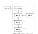
一方、透析装置本体6には、図2に示すように、ΔBV%演算手段11と、記憶手段12と、監視手段13と、透析装置本体6が具備するディスプレイ等から成る表示手段14と、音声出力可能なスピーカ等から成る報知手段15とが配設されている。このうちΔBV%演算手段11は、前述した検出手段5と電気的に接続されており、当該検出手段5から送信されたヘマトクリット値に基づき循環血液量変化率(ΔBV%)を演算して求めるためのものである。
On the other hand, as shown in FIG. 2, the dialyzer body 6 includes ΔBV% calculation means 11, storage means 12, monitoring means 13, display means 14 including a display provided in the dialyzer body 6, and voice. An informing means 15 comprising a speaker capable of outputting is disposed. Of these, the ΔBV% calculating means 11 is electrically connected to the detecting
即ち、透析治療過程で体外循環する血液の濃度に係るパラメータ(血液指標)であるヘマトクリット値を検出手段5(ヘマトクリットセンサ)にて逐次測定するとともに、そのヘマトクリット値に基づいてΔBV%演算手段11が循環血液量変化率(ΔBV%)を演算することにより、時系列的に複数時点で測定した時系列データ(透析治療時における循環血液量変化率の経時的変化傾向を示すデータ)を得ることができるのである。 That is, the hematocrit value, which is a parameter (blood index) related to the concentration of blood circulating extracorporeally in the dialysis treatment process, is sequentially measured by the detecting means 5 (hematocrit sensor), and the ΔBV% calculating means 11 is based on the hematocrit value. By calculating the circulatory blood volume change rate (ΔBV%), it is possible to obtain time-series data (data indicating a change tendency with time of the circulatory blood volume change rate during dialysis treatment) measured at a plurality of time points in time series. It can be done.
因みに、検出手段5(ヘマトクリットセンサ)にて得られるヘマトクリット値をHtとおくと、循環血液量の変化率ΔBV%は、(透析開始時のHt−測定時のHt)/測定時のHt×100なる演算式から求めることができる。これにより、透析治療時間経過に伴って患者の循環血液量の変化率(ΔBV%)を逐次検出することができ、当該透析治療における時系列データを得ることができる。 Incidentally, if the hematocrit value obtained by the detection means 5 (hematocrit sensor) is set to Ht, the change rate ΔBV% of the circulating blood volume is (Ht at the start of dialysis−Ht at the time of measurement) / Ht × 100 at the time of measurement. It can obtain | require from the computing equation which becomes. Thereby, the change rate (ΔBV%) of the circulating blood volume of the patient can be sequentially detected as the dialysis treatment time elapses, and time series data in the dialysis treatment can be obtained.
然るに、上記ΔBV%演算手段11は、測定されたヘマトクリット値に基づいて循環血液量変化率(ΔBV%)を求めているが、これに代えて例えばヘモグロビン濃度や血清総蛋白濃度などに基づいて循環血液量変化率(ΔBV%)を用いてもよい。更に、循環血液量変化率(ΔBV%)を求めるためのパラメータ(血液指標)を測定するにあたり、光学的或いは超音波等種々形態のものを使用することができる。 However, the ΔBV% calculating means 11 obtains the circulating blood volume change rate (ΔBV%) based on the measured hematocrit value, but instead circulates based on, for example, hemoglobin concentration or serum total protein concentration. The blood volume change rate (ΔBV%) may be used. Furthermore, in measuring a parameter (blood index) for determining the rate of change in circulating blood volume (ΔBV%), various forms such as optical or ultrasonic can be used.
記憶手段12は、適正であれば検出手段5で検出されると予測される血液指標(本実施形態においてはヘマトクリット値から求められる循環血液量変化率(ΔBV%))の経時的な適正範囲を記憶可能な例えばメモリ等から成る。この記憶手段12は、複数又は同一の患者に対して過去の透析治療において適正な透析治療であったと判定された時系列データのみを複数取得し、その累積的に蓄積された時系列データから循環血液量変化率(ΔBV%))の経時的な適正範囲を求め、記憶するよう構成されている。
The
例えば、記憶手段12にて取得した時系列データに所定の演算を行って標準化し、患者の体重又は除水量など特定患者固有の条件に関わらない普遍的な時系列データとした後、適正推移(経時的変化)を算出する。時系列データの標準化は、例えば透析治療で得られたΔBV%値(変数)を、その透析治療前後の体重変化率(ΔBW%)で除する演算(ΔBV%/最終ΔBW%)にて行うことができ、当該体重変化率(ΔBW%)は、次に示す式1にて算出することができる。
For example, the time series data acquired by the
ΔBW%=(BW1−BW2)/BW1×100(%)
=(UFV)/BW1×100(%)…(式1)
ΔBW% = (BW1-BW2) / BW1 × 100 (%)
= (UFV) / BW1 × 100 (%) (Formula 1)
具体的には、当該式1における除水積算値(UFV)の項にその透析治療(適正な透析治療)における目標除水量を、前体重(BW1)の項に患者の前体重(透析治療前の体重)をそれぞれ代入することにより、標準化されて特定患者固有の条件に関わらない普遍的な時系列データを得ることができる。尚、かかる時系列データの標準化のための算出を、記憶手段12とは別個の外部手段にて行わせるよう構成してもよい。
Specifically, the target water removal amount in the dialysis treatment (appropriate dialysis treatment) is indicated in the term of integrated water removal value (UFV) in Equation 1, and the patient's previous weight (before dialysis treatment) is indicated in the previous weight (BW1) term. By substituting each of the weights, it is possible to obtain universal time-series data that is standardized and not related to conditions specific to a specific patient. The calculation for standardization of the time series data may be performed by an external unit that is separate from the
而して、標準化された時系列データに対して例えば回帰計算を施して曲線回帰を図り(即ち相関性を見いだす)、適正な透析治療過程において予想される時系列データの適正推移を算出することができる。更に、標準化された時系列データの分布から、測定時点毎(体外循環する血液の濃度(血液指標)に係るパラメータ(本実施形態においてはΔBV%)の測定時点毎)における下限値から上限値までの所定幅を持った適正範囲(血液指標の経時的な適正範囲)を算出することができる。このように求められた適正範囲は記憶手段12にて記憶され、その適正範囲をグラフ化すると、図3で示すように、透析治療時間経過に伴う上限の関数(α)と下限値の関数(β)との間のハッチングで示された部位とされる。 Thus, for example, a regression calculation is performed on the standardized time series data to perform a curve regression (that is, find a correlation), and an appropriate transition of the time series data expected in an appropriate dialysis treatment process is calculated. Can do. Furthermore, from the distribution of the standardized time-series data, from the lower limit value to the upper limit value at each measurement time point (each measurement time point of the parameter (ΔBV% in this embodiment) related to the concentration of blood circulating outside the body (blood index)) It is possible to calculate an appropriate range having a predetermined width (appropriate range over time of the blood index). The appropriate range obtained in this way is stored in the storage means 12, and when the appropriate range is graphed, as shown in FIG. 3, an upper limit function (α) and a lower limit function ( It is set as the site | part shown by hatching between (beta).
監視手段13は、例えば透析装置本体6内に配設されたマイコン等から成り、記憶手段12で記憶された血液指標(ΔBV%)の適正範囲と、検出手段5で実際に検出された実血液指標(実際に検出されたヘマトクリット値Htから求められるΔBV%)とを比較し、当該実血液指標が当該適正範囲内(上限αと下限βとの間)にあるか否かを経時的に(リアルタイムに)監視し得るものである。 The monitoring means 13 is composed of, for example, a microcomputer or the like disposed in the dialyzer body 6, and the appropriate range of the blood index (ΔBV%) stored in the storage means 12 and the actual blood actually detected by the detection means 5. An index (ΔBV% obtained from the actually detected hematocrit value Ht) is compared, and whether or not the actual blood index is within the appropriate range (between the upper limit α and the lower limit β) over time ( It can be monitored (in real time).
表示手段14は、本血液透析装置にて透析治療を行う際、記憶手段12で記憶された適正推移範囲をグラフとして表示しつつΔBV%演算手段11にて求められた循環血液量変化率(ΔBV%)を当該グラフに重ね合わせて経時的に(リアルタイムに)表示するものである。これにより、透析治療の過程において、実血液指標が適正範囲内(上限αと下限βとの間)にあるか否かの判別を視覚的に行わせることができるとともに、循環血液量変化率(ΔBV%)が上限値又は下限値を超える兆候を察知することができる。
When the dialysis treatment is performed by the hemodialyzer, the
報知手段15は、透析治療を行う際、測定された循環血液量変化率(ΔBV%)が記憶手段12で記憶された適正推移範囲から逸脱したことを条件として、所定の報知を行うものであり、例えば音声等を出力し得るスピーカや光を照射し得る光源(LEDなど)から成るものである。例えば、透析治療過程において、求められた循環血液量変化率(ΔBV%)が適正推移範囲の上限値又は下限値を超えた場合は、これらを踏まえたガイダンスを行うことができる。
The
このように、透析治療を行う際、求められたパラメータ(血液指標)が記憶手段12にて記憶された適正推移範囲から逸脱したことを条件として、所定の報知を行うので、医療従事者の注意を促すことができる。尚、報知手段15による報知やガイダンス内容を記録に残し、その後の透析治療に活用すようにしてもよい。 Thus, when performing dialysis treatment, a predetermined notification is performed on the condition that the obtained parameter (blood index) has deviated from the appropriate transition range stored in the storage means 12, so that the medical worker's attention Can be encouraged. Note that the notification by the notification means 15 and the contents of the guidance may be recorded and used for subsequent dialysis treatment.
ここで、本実施形態においては、検出手段5で検出される血液指標の経時的変化が安定するまでの立上がり時間経過後、記憶手段12で記憶された血液指標(ΔBV%)の経時的な適正範囲を設定し、監視手段13による監視を行わせるようになっている。かかる立上がり時間は、シャント再循環や低ナトリウム血症、低蛋白血症、或いは立位から臥位への体位変更に伴う水分の移動などにより、ヘマトクリット値などの検出される血液指標が不安定となってしまう時間を言う。
Here, in this embodiment, after the rise time until the time-dependent change of the blood index detected by the detection means 5 becomes stable, the blood index (ΔBV%) stored in the storage means 12 is appropriate over time. A range is set and monitoring by the
そして、立上がり時間は、検出手段5により検出された実血液指標に基づき、所定の演算式にて求められるよう構成されている。例えば、立上がり時間は、検出手段5で検出した実血液指標値の所定時間あたりの変化率又は変化量が予め定められた許容範囲内であると判定されるまでの時間とされており、図5〜8に示す治療開始から「T1」で示される時間までを指す。 The rise time is configured to be obtained by a predetermined arithmetic expression based on the actual blood index detected by the detection means 5. For example, the rise time is a time until it is determined that the rate of change or amount of change of the actual blood index value detected by the detection means 5 per predetermined time is within a predetermined allowable range. It refers to the time indicated by “T1” from the start of treatment shown in FIG.
以下、本実施形態における血液指標値(ΔBV%)の経時的変化が安定したか否かの具体的手法としては、図4の如く血液指標値(ΔBV%)が経時的に検出された場合、一定区間の面積(積算値)(同図中V1〜Vn)を用いるもの、一定区間の平均値(同図中X0〜X1、X1〜X2…の平均値)を用いるもの、或いは一定区間の一次関数的な傾き(同図中X0〜X1、X1〜X2…の近似直線の傾き)を用いるもの、が挙げられる。 Hereinafter, as a specific method for determining whether or not the change over time of the blood index value (ΔBV%) in the present embodiment is stable, when the blood index value (ΔBV%) is detected over time as shown in FIG. One using an area (integrated value) in a certain section (V1 to Vn in the figure), one using an average value in a certain section (an average value of X0 to X1, X1 to X2 in the figure), or primary of a certain section Those using functional gradients (inclinations of approximate straight lines of X0 to X1, X1 to X2.
上記一定区間の面積(積算値)(同図中V1〜Vn)を用いるものを例として挙げる場合、血液指標値(ΔBV%)の経時的変化が安定したか否かの判定は、以下の2つの手法が考えられる。
即ち、最初に検出される面積V1を基準として、当該面積V1と次に検出される面積V2とを比較して、例えば、(V2−V1)/V1×100(%)なる演算式にて増減値を求め、その増減値(この場合は「所定時間あたりの変化率」に相当する)が予め定められた許容範囲内か否かを判定する。判定の結果、許容範囲であれば1カウントするとともに、次に面積V1と面積V3とを比較して増減値を求め、その増減値が許容範囲内か否かを判定するとともに、カウントを1増加させる。以下、同様に、面積V1を基準とした比較が順次行われることとなる。
In the case of using an example using the above-described constant section area (integrated value) (V1 to Vn in the figure), it is determined whether or not the change over time of the blood index value (ΔBV%) is stable as follows. There are two approaches.
That is, using the area V1 detected first as a reference, the area V1 is compared with the area V2 detected next, for example, (V2−V1) / V1 × 100 (%). A value is obtained, and it is determined whether the increase / decrease value (corresponding to “change rate per predetermined time” in this case) is within a predetermined allowable range. If the result of the determination is an allowable range, the count is incremented by 1 and the area V1 is compared with the area V3 to determine an increase / decrease value. Let Hereinafter, similarly, the comparison based on the area V1 is sequentially performed.
一方、面積V1と次に検出される面積V2とを比較して、その増減値が予め定められた許容範囲外である場合、カウントは行わず、次に面積V2と面積V3との比較され、その増減値が予め定められた許容範囲内であるか否かが判定される。当該許容判定内であれば、上記の如く1カウントする一方、当該許容範囲外であればカウントしない。尚、当該許容範囲外となった場合、カウントはクリアされる(即ち「0」となる)。 On the other hand, when the area V1 is compared with the area V2 to be detected next, and the increase / decrease value is outside the predetermined allowable range, the area V2 is compared with the area V3 without counting. It is determined whether the increase / decrease value is within a predetermined allowable range. If it is within the permissible determination, 1 is counted as described above, while if it is out of the permissible range, it is not counted. Note that the count is cleared (ie, becomes “0”) when it falls outside the permissible range.
こうして、順次判定を行い、カウントが所定数(例えば「3」)となったことを条件として、血液指標値(ΔBV%)の経時的推移が安定したと判定するようになっている。即ち、経時的な検出値を複数区間に区切り、隣接する区間の増減値が所定回数連続して許容範囲内となった時点で監視手段13により経時的推移が安定したと判定されるのである。 In this way, the determination is sequentially performed, and it is determined that the temporal transition of the blood index value (ΔBV%) is stable on the condition that the count reaches a predetermined number (for example, “3”). That is, the temporally detected values are divided into a plurality of sections, and when the increase / decrease value of the adjacent sections is continuously within the allowable range a predetermined number of times, the monitoring means 13 determines that the temporal transition is stable.
上記手法に代えて、例えば面積V1と次に検出される面積V2とを比較して増減値を求め、その増減値が予め定められた許容範囲内である場合、1カウントするとともに、次に面積V2と面積V3とを比較(以下、面積V3と面積V4…)して増減値を求め、その増減値が許容範囲内か否かを順次判定してカウントするものとしてもよい。また、上記のものにおいては、増減値が所定時間あたりの変化率とされているが、所定時間あたりの変化量を用いて許容範囲内か否かを判定するよう構成してもよい。 Instead of the above method, for example, the area V1 is compared with the area V2 to be detected next to obtain an increase / decrease value, and when the increase / decrease value is within a predetermined allowable range, one count is performed and the next area An increase / decrease value may be obtained by comparing V2 and area V3 (hereinafter, area V3 and area V4...), And whether or not the increase / decrease value is within an allowable range may be sequentially determined and counted. Further, in the above, the increase / decrease value is the rate of change per predetermined time, but it may be configured to determine whether it is within the allowable range using the amount of change per predetermined time.
上記実施形態によれば、検出手段5で検出した血液指標値(ヘマトクリット値)から求められた血液指標(ΔBV%)の経時的変化(経時的推移)が安定したか否かを自動的に判定することができる。而して、立上がり時間経過後、記憶手段12で記憶された血液指標(ΔBV%)の経時的な適正範囲を設定し、監視手段13による監視を行わせるよう構成されている。そのときの経時的な適正範囲の設定方法について以下に説明する。
According to the above-described embodiment, it is automatically determined whether or not the change over time (change over time) of the blood index (ΔBV%) obtained from the blood index value (hematocrit value) detected by the detection means 5 is stable. can do. Thus, after the rise time has elapsed, an appropriate range over time of the blood index (ΔBV%) stored in the
例えば、図5に示すように、立上がり時間T1における実血液指標値(実際に検出されたヘマトクリット値から求められたΔBV%値:以下、同様)が適正範囲の上限(α)と下限(β)との中間の位置となるよう、当該適正範囲をグラフ中上下方向(ΔBV%軸方向)のみに平行移動させる方法、或いは図6に示すように、立上がり時間T1における実血液指標値の位置をゼロ点(治療開始時と擬制)として適正範囲を設定し直す方法が挙げられる。 For example, as shown in FIG. 5, the actual blood index value at the rise time T1 (ΔBV% value obtained from the actually detected hematocrit value: the same applies hereinafter) is the upper limit (α) and lower limit (β) of the appropriate range. A method of translating the appropriate range only in the vertical direction (ΔBV% axis direction) in the graph so as to be in the middle of the position, or as shown in FIG. 6, the position of the actual blood index value at the rise time T1 is zero. As a point (at the start of treatment and imitation), there is a method of resetting the appropriate range.
また、図7に示すように、立上がり時間T1における実血液指標値を初期化してゼロ点(当該実血液指標値をゼロまで移動)とし、そのゼロ点が適正範囲の上限(α)と下限(β)との中間の位置となるよう当該適正範囲をグラフ中上下方向(ΔBV%軸方向)のみに平行移動させる方法、或いは図8に示すように、立上がり時間T1における実血液指標値を初期化してゼロ点(当該実血液指標値をゼロまで移動)とし、そのゼロ点から適正範囲を設定し直す方法等が挙げられる。尚、図5〜8のグラフにおいては、横軸が時間(治療時間)とされているが、これを透析達成率や除水達成率等、他のパラメータとしてもよい。 Further, as shown in FIG. 7, the actual blood index value at the rising time T1 is initialized to a zero point (the actual blood index value is moved to zero), and the zero point is the upper limit (α) and lower limit ( A method in which the appropriate range is translated only in the vertical direction (ΔBV% axis direction) in the graph so as to be in the middle position with respect to β), or the actual blood index value at the rise time T1 is initialized as shown in FIG. A zero point (moving the actual blood index value to zero), and setting an appropriate range from the zero point. In the graphs of FIGS. 5 to 8, the horizontal axis is time (treatment time), but this may be used as another parameter such as a dialysis achievement rate or a water removal achievement rate.
上記実施形態によれば、検出手段5で検出される血液指標(ヘマトクリット値)から求められた血液指標(ΔBV%)の経時的変化が安定するまでの立上がり時間T1経過後、記憶手段12で記憶された血液指標(ΔBV%)の経時的な適正範囲を設定し、監視手段13による監視を行わせるので、立上がり時間T1を考慮して適切に適正範囲を設定することにより、血液指標(ΔBV%)の経時的変化の監視を精度よく行わせることができる。 According to the above embodiment, the storage means 12 stores the rise time T1 until the change over time of the blood index (ΔBV%) obtained from the blood index (hematocrit value) detected by the detection means 5 becomes stable. Since an appropriate range over time of the blood index (ΔBV%) is set and monitoring is performed by the monitoring means 13, the blood index (ΔBV%) is set by appropriately setting the appropriate range in consideration of the rise time T1. ) Over time can be accurately monitored.
また、立上がり時間T1は、検出手段5により検出された実血液指標に基づき、所定の演算式にて求められるので、立上がり時間T1経過後の血液指標の経時的な適正範囲の設定を自動化することができる。更に、立上がり時間T1は、検出手段5で検出した実血液指標値の所定時間あたりの変化率又は変化量が予め定められた許容範囲内であると判定されるまでの時間とされるので、立上がり時間T1経過後の血液指標の経時的な適正範囲の設定をより確実且つスムーズに行わせつつ自動化を図ることができる。
Further, since the rise time T1 is obtained by a predetermined arithmetic expression based on the actual blood index detected by the detecting
以上、本実施形態について説明したが、本発明はこれに限定されるものではなく、例えば入力手段を具備させ、その入力手段により立上がり時間T1を入力するよう構成してもよい。このように、立上がり時間T1が予め操作者により設定された時間であれば、特定の患者における過去の傾向を加味しつつその患者固有の立上がり時間を容易且つスムーズに設定することができる。かかる立上がり時間T1における監視手段13による監視対象は、本実施形態の如くΔBV%の他、ヘマトクリット値であってもよく、或いは他の血液指標値であってもよい。 Although the present embodiment has been described above, the present invention is not limited to this. For example, an input unit may be provided and the rise time T1 may be input by the input unit. Thus, if the rise time T1 is a time set in advance by the operator, the rise time unique to the patient can be set easily and smoothly while taking into account past trends in a specific patient. The monitoring target by the monitoring means 13 at the rising time T1 may be a hematocrit value or other blood index value in addition to ΔBV% as in the present embodiment.
また、検出手段5は、動脈側血液回路1a及び静脈側血液回路1bであれば何れの部位に配設するようにしてもよく、或いは動脈側血液回路1a及び静脈側血液回路1bの双方に配設するよう構成してもよい。更に、本実施形態においては、検出手段はヘマトクリット値を検知するものであるが、他の血液指標(血液に関するパラメータ)を検知するものであってもよい。尚、本実施形態においては、透析装置本体6が透析液供給機構が内蔵されない透析監視装置から成るものであるが、透析液供給機構が内蔵された個人用透析装置に適用するようにしてもよい。 Further, the detection means 5 may be disposed in any part as long as it is the arterial blood circuit 1a and the venous blood circuit 1b, or may be disposed in both the arterial blood circuit 1a and the venous blood circuit 1b. You may comprise so that it may provide. Furthermore, in the present embodiment, the detection means detects the hematocrit value, but may detect other blood indices (parameters related to blood). In the present embodiment, the dialysis device body 6 is composed of a dialysis monitoring device that does not incorporate a dialysate supply mechanism, but may be applied to a personal dialysis device that incorporates a dialysate supply mechanism. .
検出手段で検出される血液指標の経時的変化が安定するまでの立上がり時間経過後、記憶手段で記憶された血液指標の経時的な適正範囲を設定し、監視手段による監視を行わせる血液浄化装置であれば、体外循環させつつ血液浄化を行う他の治療(血液濾過療法や血液濾過透析療法など)で使用されるもの或いは他の機能が付加されたものにも適用することができる。 A blood purification device that sets an appropriate range over time of the blood index stored in the storage means and monitors by the monitoring means after the rise time until the change in the blood index detected by the detection means becomes stable If so, it can be applied to those used in other treatments (blood filtration therapy, hemofiltration dialysis therapy, etc.) that purify blood while circulating extracorporeally, or those to which other functions are added.
1…血液回路
1a…動脈側血液回路
1b…静脈側血液回路
2…ダイアライザ(血液浄化手段)
3…血液ポンプ
4a、4b…ドリップチャンバ
5…検出手段
6…透析装置本体
7…透析液導入ライン
8…透析系排出ライン
9…バイパスライン
10…除水ポンプ
11…ΔBV%演算手段
12…記憶手段
13…監視手段
14…表示手段
15…報知手段
P …複式ポンプ
T1…立上がり時間
DESCRIPTION OF SYMBOLS 1 ... Blood circuit 1a ... Arterial side blood circuit 1b ... Vein
DESCRIPTION OF SYMBOLS 3 ...
Claims (4)
前記動脈側血液回路と静脈側血液回路との間に接続され、当該血液回路を流れる血液を浄化する血液浄化手段と、
前記血液回路で体外循環する患者の血液における血液指標を経時的に検出する検出手段と、
適正であれば前記検出手段で検出されると予測される血液指標の経時的な適正範囲を記憶する記憶手段と、
該記憶手段で記憶された血液指標の適正範囲と、前記検出手段で実際に検出された実血液指標とを比較し、当該実血液指標が当該適正範囲内にあるか否かを経時的に監視し得る監視手段と、
を具備した血液浄化装置であって、
前記検出手段で検出される血液指標の経時的変化が安定するまでの立上がり時間経過後、前記記憶手段で記憶された血液指標の経時的な適正範囲を設定し、前記監視手段による監視を行わせることを特徴とする血液浄化装置。 A blood circuit comprising an arterial blood circuit and a venous blood circuit for extracorporeal circulation of the patient's blood;
Blood purification means connected between the arterial blood circuit and the venous blood circuit and purifying blood flowing through the blood circuit;
A detecting means for detecting a blood index in the blood of a patient circulating extracorporeally in the blood circuit over time;
Storage means for storing an appropriate range over time of a blood index that is predicted to be detected by the detection means if appropriate;
The appropriate range of the blood index stored in the storage means is compared with the actual blood index actually detected by the detection means, and it is monitored over time whether the actual blood index is within the appropriate range. Possible monitoring means;
A blood purification apparatus comprising:
After the rise time until the change over time of the blood index detected by the detection means becomes stable, an appropriate range over time of the blood index stored in the storage means is set, and monitoring by the monitoring means is performed. The blood purification apparatus characterized by the above-mentioned.
Priority Applications (1)
| Application Number | Priority Date | Filing Date | Title |
|---|---|---|---|
| JP2008232812A JP5438939B2 (en) | 2008-09-11 | 2008-09-11 | Blood purification equipment |
Applications Claiming Priority (1)
| Application Number | Priority Date | Filing Date | Title |
|---|---|---|---|
| JP2008232812A JP5438939B2 (en) | 2008-09-11 | 2008-09-11 | Blood purification equipment |
Publications (2)
| Publication Number | Publication Date |
|---|---|
| JP2010063644A true JP2010063644A (en) | 2010-03-25 |
| JP5438939B2 JP5438939B2 (en) | 2014-03-12 |
Family
ID=42189776
Family Applications (1)
| Application Number | Title | Priority Date | Filing Date |
|---|---|---|---|
| JP2008232812A Active JP5438939B2 (en) | 2008-09-11 | 2008-09-11 | Blood purification equipment |
Country Status (1)
| Country | Link |
|---|---|
| JP (1) | JP5438939B2 (en) |
Cited By (4)
| Publication number | Priority date | Publication date | Assignee | Title |
|---|---|---|---|---|
| WO2014162330A1 (en) * | 2013-04-01 | 2014-10-09 | テルモ株式会社 | Circulation device and method for controlling same |
| JP2019083892A (en) * | 2017-11-02 | 2019-06-06 | 日東電工株式会社 | Management system of drain drainage |
| JP2020142107A (en) * | 2014-08-20 | 2020-09-10 | フレゼニウス メディカル ケア ドイッチェランド ゲゼルシャフト ミット ベシュレンクテル ハフツング | Dialysis machine having capability of determining predialytic property in blood of dialysis patient |
| JP2022500182A (en) * | 2018-09-19 | 2022-01-04 | フレセニウス メディカル ケア ホールディングス インコーポレーテッド | Techniques for dialysis based on relative blood volume |
Citations (4)
| Publication number | Priority date | Publication date | Assignee | Title |
|---|---|---|---|---|
| JPH11221275A (en) * | 1997-12-03 | 1999-08-17 | Jms Co Ltd | Blood treating device |
| JP2004097781A (en) * | 2002-07-18 | 2004-04-02 | Nikkiso Co Ltd | Blood treatment apparatus and blood treatment method |
| JP2007000238A (en) * | 2005-06-22 | 2007-01-11 | Nikkiso Co Ltd | Dialysis treatment device |
| JP2007167109A (en) * | 2005-12-19 | 2007-07-05 | Jms Co Ltd | Alarm monitoring system of venous pressure and dialysing fluid pressure in hemodialysis apparatus |
-
2008
- 2008-09-11 JP JP2008232812A patent/JP5438939B2/en active Active
Patent Citations (4)
| Publication number | Priority date | Publication date | Assignee | Title |
|---|---|---|---|---|
| JPH11221275A (en) * | 1997-12-03 | 1999-08-17 | Jms Co Ltd | Blood treating device |
| JP2004097781A (en) * | 2002-07-18 | 2004-04-02 | Nikkiso Co Ltd | Blood treatment apparatus and blood treatment method |
| JP2007000238A (en) * | 2005-06-22 | 2007-01-11 | Nikkiso Co Ltd | Dialysis treatment device |
| JP2007167109A (en) * | 2005-12-19 | 2007-07-05 | Jms Co Ltd | Alarm monitoring system of venous pressure and dialysing fluid pressure in hemodialysis apparatus |
Cited By (7)
| Publication number | Priority date | Publication date | Assignee | Title |
|---|---|---|---|---|
| WO2014162330A1 (en) * | 2013-04-01 | 2014-10-09 | テルモ株式会社 | Circulation device and method for controlling same |
| JP5997368B2 (en) * | 2013-04-01 | 2016-09-28 | テルモ株式会社 | Circulation device and control method thereof |
| US9889245B2 (en) | 2013-04-01 | 2018-02-13 | Terumo Kabushiki Kaisha | Circulation apparatus and method for controlling same |
| JP2020142107A (en) * | 2014-08-20 | 2020-09-10 | フレゼニウス メディカル ケア ドイッチェランド ゲゼルシャフト ミット ベシュレンクテル ハフツング | Dialysis machine having capability of determining predialytic property in blood of dialysis patient |
| JP2019083892A (en) * | 2017-11-02 | 2019-06-06 | 日東電工株式会社 | Management system of drain drainage |
| JP2022500182A (en) * | 2018-09-19 | 2022-01-04 | フレセニウス メディカル ケア ホールディングス インコーポレーテッド | Techniques for dialysis based on relative blood volume |
| JP7297876B2 (en) | 2018-09-19 | 2023-06-26 | フレセニウス メディカル ケア ホールディングス インコーポレーテッド | Techniques for dialysis based on relative blood volume |
Also Published As
| Publication number | Publication date |
|---|---|
| JP5438939B2 (en) | 2014-03-12 |
Similar Documents
| Publication | Publication Date | Title |
|---|---|---|
| JP4822258B2 (en) | Hemodialysis machine | |
| JP4868772B2 (en) | Blood purification equipment | |
| JP4726045B2 (en) | Hemodialysis machine | |
| JP4573860B2 (en) | Blood purification equipment | |
| TWI450738B (en) | Blood-purifying device | |
| JP4925159B2 (en) | Blood purification equipment | |
| EP3042672B1 (en) | Blood purification apparatus | |
| JP4290106B2 (en) | Blood purification equipment | |
| JP4573231B2 (en) | Blood purification equipment | |
| JP5438939B2 (en) | Blood purification equipment | |
| JP4905475B2 (en) | Dialysis machine | |
| JP5222706B2 (en) | Blood purification apparatus and blood flow calculation method thereof | |
| CN111225694B (en) | Blood purification device | |
| JP4442825B2 (en) | Blood purification equipment | |
| JP5415038B2 (en) | Blood purification equipment | |
| US20200237988A1 (en) | Blood Purification Apparatus | |
| JP2010068927A (en) | Blood purifying apparatus | |
| JP5237007B2 (en) | Blood purification equipment |
Legal Events
| Date | Code | Title | Description |
|---|---|---|---|
| A621 | Written request for application examination |
Free format text: JAPANESE INTERMEDIATE CODE: A621 Effective date: 20110530 |
|
| A977 | Report on retrieval |
Free format text: JAPANESE INTERMEDIATE CODE: A971007 Effective date: 20121212 |
|
| A131 | Notification of reasons for refusal |
Free format text: JAPANESE INTERMEDIATE CODE: A131 Effective date: 20121219 |
|
| A521 | Request for written amendment filed |
Free format text: JAPANESE INTERMEDIATE CODE: A523 Effective date: 20130215 |
|
| A131 | Notification of reasons for refusal |
Free format text: JAPANESE INTERMEDIATE CODE: A131 Effective date: 20130904 |
|
| A521 | Request for written amendment filed |
Free format text: JAPANESE INTERMEDIATE CODE: A523 Effective date: 20131101 |
|
| TRDD | Decision of grant or rejection written | ||
| A01 | Written decision to grant a patent or to grant a registration (utility model) |
Free format text: JAPANESE INTERMEDIATE CODE: A01 Effective date: 20131206 |
|
| A61 | First payment of annual fees (during grant procedure) |
Free format text: JAPANESE INTERMEDIATE CODE: A61 Effective date: 20131216 |
|
| R150 | Certificate of patent or registration of utility model |
Ref document number: 5438939 Country of ref document: JP Free format text: JAPANESE INTERMEDIATE CODE: R150 Free format text: JAPANESE INTERMEDIATE CODE: R150 |
|
| R250 | Receipt of annual fees |
Free format text: JAPANESE INTERMEDIATE CODE: R250 |
|
| R250 | Receipt of annual fees |
Free format text: JAPANESE INTERMEDIATE CODE: R250 |
|
| R250 | Receipt of annual fees |
Free format text: JAPANESE INTERMEDIATE CODE: R250 |
|
| R250 | Receipt of annual fees |
Free format text: JAPANESE INTERMEDIATE CODE: R250 |
|
| R250 | Receipt of annual fees |
Free format text: JAPANESE INTERMEDIATE CODE: R250 |
|
| R250 | Receipt of annual fees |
Free format text: JAPANESE INTERMEDIATE CODE: R250 |