JP2010063633A - Female member of hook and loop fastener - Google Patents
Female member of hook and loop fastener Download PDFInfo
- Publication number
- JP2010063633A JP2010063633A JP2008232543A JP2008232543A JP2010063633A JP 2010063633 A JP2010063633 A JP 2010063633A JP 2008232543 A JP2008232543 A JP 2008232543A JP 2008232543 A JP2008232543 A JP 2008232543A JP 2010063633 A JP2010063633 A JP 2010063633A
- Authority
- JP
- Japan
- Prior art keywords
- knitted fabric
- loop
- warp
- yarn
- hook
- Prior art date
- Legal status (The legal status is an assumption and is not a legal conclusion. Google has not performed a legal analysis and makes no representation as to the accuracy of the status listed.)
- Granted
Links
Images


Classifications
-
- A—HUMAN NECESSITIES
- A44—HABERDASHERY; JEWELLERY
- A44B—BUTTONS, PINS, BUCKLES, SLIDE FASTENERS, OR THE LIKE
- A44B18/00—Fasteners of the touch-and-close type; Making such fasteners
- A44B18/0023—Woven or knitted fasteners
- A44B18/0034—Female or loop elements
-
- A—HUMAN NECESSITIES
- A44—HABERDASHERY; JEWELLERY
- A44B—BUTTONS, PINS, BUCKLES, SLIDE FASTENERS, OR THE LIKE
- A44B18/00—Fasteners of the touch-and-close type; Making such fasteners
-
- A—HUMAN NECESSITIES
- A61—MEDICAL OR VETERINARY SCIENCE; HYGIENE
- A61F—FILTERS IMPLANTABLE INTO BLOOD VESSELS; PROSTHESES; DEVICES PROVIDING PATENCY TO, OR PREVENTING COLLAPSING OF, TUBULAR STRUCTURES OF THE BODY, e.g. STENTS; ORTHOPAEDIC, NURSING OR CONTRACEPTIVE DEVICES; FOMENTATION; TREATMENT OR PROTECTION OF EYES OR EARS; BANDAGES, DRESSINGS OR ABSORBENT PADS; FIRST-AID KITS
- A61F13/00—Bandages or dressings; Absorbent pads
- A61F13/15—Absorbent pads, e.g. sanitary towels, swabs or tampons for external or internal application to the body; Supporting or fastening means therefor; Tampon applicators
- A61F13/56—Supporting or fastening means
- A61F13/62—Mechanical fastening means, ; Fabric strip fastener elements, e.g. hook and loop
- A61F13/622—Fabric strip fastener elements, e.g. hook and loop
- A61F13/627—Fabric strip fastener elements, e.g. hook and loop characterised by the loop
-
- D—TEXTILES; PAPER
- D04—BRAIDING; LACE-MAKING; KNITTING; TRIMMINGS; NON-WOVEN FABRICS
- D04B—KNITTING
- D04B21/00—Warp knitting processes for the production of fabrics or articles not dependent on the use of particular machines; Fabrics or articles defined by such processes
- D04B21/02—Pile fabrics or articles having similar surface features
-
- D—TEXTILES; PAPER
- D10—INDEXING SCHEME ASSOCIATED WITH SUBLASSES OF SECTION D, RELATING TO TEXTILES
- D10B—INDEXING SCHEME ASSOCIATED WITH SUBLASSES OF SECTION D, RELATING TO TEXTILES
- D10B2403/00—Details of fabric structure established in the fabric forming process
- D10B2403/01—Surface features
- D10B2403/011—Dissimilar front and back faces
- D10B2403/0112—One smooth surface, e.g. laminated or coated
-
- D—TEXTILES; PAPER
- D10—INDEXING SCHEME ASSOCIATED WITH SUBLASSES OF SECTION D, RELATING TO TEXTILES
- D10B—INDEXING SCHEME ASSOCIATED WITH SUBLASSES OF SECTION D, RELATING TO TEXTILES
- D10B2501/00—Wearing apparel
- D10B2501/06—Details of garments
- D10B2501/063—Fasteners
- D10B2501/0632—Fasteners of the touch-and-close type
-
- Y—GENERAL TAGGING OF NEW TECHNOLOGICAL DEVELOPMENTS; GENERAL TAGGING OF CROSS-SECTIONAL TECHNOLOGIES SPANNING OVER SEVERAL SECTIONS OF THE IPC; TECHNICAL SUBJECTS COVERED BY FORMER USPC CROSS-REFERENCE ART COLLECTIONS [XRACs] AND DIGESTS
- Y10—TECHNICAL SUBJECTS COVERED BY FORMER USPC
- Y10T—TECHNICAL SUBJECTS COVERED BY FORMER US CLASSIFICATION
- Y10T24/00—Buckles, buttons, clasps, etc.
- Y10T24/27—Buckles, buttons, clasps, etc. including readily dissociable fastener having numerous, protruding, unitary filaments randomly interlocking with, and simultaneously moving towards, mating structure [e.g., hook-loop type fastener]
- Y10T24/2775—Buckles, buttons, clasps, etc. including readily dissociable fastener having numerous, protruding, unitary filaments randomly interlocking with, and simultaneously moving towards, mating structure [e.g., hook-loop type fastener] having opposed structure formed from distinct filaments of diverse shape to those mating therewith
Abstract
Description
本発明は、面ファスナ雌材、該面ファスナ雌材を有する面ファスナ、及び該面ファスナを有する吸収性物品に関する。 The present invention relates to a hook-and-loop fastener female material, a hook-and-loop fastener having the hook-and-loop fastener female material, and an absorbent article having the hook-and-loop fastener.
面ファスナは、フローリング床材の固定、衣類の開閉用途などに広く用いられており、また、着脱が簡便なことから、オムツ等の吸収性物品の係合にも使用されている。面ファスナは、雄材、及びそれと係合する雌材で構成されており、具体的には、雌材のループが雄材のフックと係合することによって係止される。従来から、雄材と充分な係合力を有する雌材の開発が行われている。 The hook-and-loop fastener is widely used for fixing flooring flooring, opening and closing clothes, and is also used for engaging absorbent articles such as diapers because it is easy to attach and detach. The hook-and-loop fastener is composed of a male member and a female member engaged therewith. Specifically, the loop of the female member is locked by engaging the hook of the male member. Conventionally, a female material having sufficient engagement force with a male material has been developed.
特許文献1には、長さの異なる立毛によって形成された柄、特に立毛リブを有する経編地の製法であって、立毛を形成する糸を地編地の編目にからみ込み、次いでからみ込み個所の間で切り離す形式の経編地の製法が記載されている。
特許文献2には、互いに平行なウェールの網目をステッチにより形成する経糸ウェールと前記経糸ウェールとの結合により下地を形成する横糸とで構成される下地と、前記下地に編付けられた2つの脚を備えた編みループ付織物が記載されており、前記織物において、前記横糸と前記ウェールとの前記結合が、第二ウェールと第四ウェールはウェールの網目において第一ウェールと第三ウェールの間に配され、かつ、ループの2つの脚はそれぞれ、第二及び第四ステッチに編付けられることが記載されている。 In Patent Document 2, a base composed of warp wales formed by stitching a mesh of parallel wales and a weft forming a base by combining the warp wales, and two legs knitted on the base A knitted looped woven fabric comprising a knitted loop, wherein the weft and the wales are joined together, and the second wales and the fourth wales are between the first wales and the third wales in the mesh of wales. It is described that the two legs of the loop are knitted into the second and fourth stitches, respectively.
特許文献3には、フックを受け入れるループを形成した経編地を介して基材面に接合した構造を有し、経編地が後筬に筬通しした糸で振り組織、中筬に筬通しした糸で振り組織と係合しかつ編み方向に隣接するループパイルの向きが左右互い違いで形成されるループパイル編組織、及び前筬に筬通しした糸で振り組織乃至ループパイル形成組織と係合する地組織でそれぞれ編まれている経編地で構成されることを特徴とするフック・アンド・ループタイプの面ファスナ雌材片が記載されている。
雄材との係合力に優れ、またその係合力の左右差が少なく、更に、簡便に生産可能な面ファスナ雌材が求められている。 There is a demand for a hook-and-loop female material that is excellent in engagement force with a male material, has little difference in right and left engagement force, and can be easily produced.
本発明は、経糸、緯糸及びループ糸から構成される編地、並びに基材を含む面ファスナ雌材であって、経糸は、開き目と閉じ目を交互に繰り返す鎖編糸からなり、ループ糸は、ループ糸の開き目のみに経糸の閉じ目のみが係合して、経糸と固定されており、ループ糸は編地の一方の表面からのみ、経糸に対して左右交互に突出している。 The present invention relates to a knitted fabric composed of a warp, a weft and a loop yarn, and a hook-and-loop fastener female material including a base material, wherein the warp is composed of a chain knitting yarn that alternately repeats an opening and a closing, In this case, only the opening of the loop yarn is engaged with only the closing of the warp and is fixed to the warp. The loop yarn protrudes alternately from the left and right of the warp yarn only from one surface of the knitted fabric.
本発明の面ファスナ雌材は、雄材との係合力に優れ、またその係合力の左右差が少ない。また、本発明の面ファスナ雌材は、簡便に生産することができ、紙おむつ等の吸収性物品における面ファスナ用雌材として好適に使用される。 The surface fastener female material of the present invention is excellent in the engaging force with the male material, and there is little difference in the right and left of the engaging force. Moreover, the surface fastener female material of this invention can be produced simply and is suitably used as a female material for surface fasteners in absorbent articles such as disposable diapers.
以下、本発明の一実施形態について、図面を参照しながら、より詳細な説明を行う。なお、本発明の面ファスナ雌材は、以下の実施形態に限定されるものではない。 Hereinafter, an embodiment of the present invention will be described in more detail with reference to the drawings. In addition, the surface fastener female material of this invention is not limited to the following embodiment.
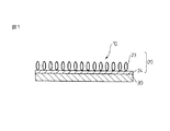
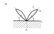
本発明の面ファスナ雌材10は、図1に模式的に示されるように、経糸21(図示せず)、緯糸22(図示せず)、及びループ糸23から構成される編地20、並びに基材30を含む。編地20において、ループ糸23が編地20のパイルを形成し、経糸21と緯糸22が編地20の地組織24を形成しており、ループ糸23は、編地20の一方の表面からのみ、経糸21に対して左右交互に突出している。
As schematically shown in FIG. 1, the surface fastener
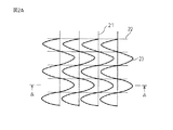
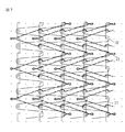
図2Aは、図1の構造を有する編地20の編組織を模式的に示す図であり、図3Aはこの編組織のパターンを模式的に示した図、図3Bは、図3Aの編組織のパターンを、経糸21、緯糸22及びループ糸23に分解して示した図である。図3A及び図3Bに示されるように、編地20において、経糸21は、開き目21aと閉じ目21bを交互に繰り返す鎖編糸からなっており、また、ループ糸23は、ループ糸23の開き目23aのみに経糸21の閉じ目21bのみが係合して、経糸21と固定されている。緯糸22は、経糸21の開き目21a及び閉じ目21bで経糸21に固定されている。このような編み組織を有することにより、ループ糸23は、編地20の一方の表面からのみ、経糸21に対して左右交互に突出する構造となる。
2A is a diagram schematically showing a knitting structure of the knitted
以下、図3A及び図3Bを参照しながら、編地20の編組織を説明する。
Hereinafter, the knitting structure of the knitted
経糸21は、1−0/0−1/0−1/1−0のパターンが繰り返された鎖編みにより形成され、このパターンの繰り返しにより、上述の通り、開き目21aと閉じ目21bとが交互に繰り返される鎖編糸を構成している。経糸21は、編地20の地組織24(中筬)となる。
The
ループ糸23は、経糸21に対して、左右に繰り出されることで編地20のパイル(前筬)となる。すなわち、ループ糸23は、まず、編地20の所定の針位置において左から右へ閉じ目又は開き目(図3A及び図3Bにおいては閉じ目)によりラップされ右方向に繰り出される。そして、右に繰り出されたループ糸23は開き目23aの状態で経糸21の閉じ目21bに係合され、更に編地20の右方向に繰り出される。次いで、編地20の所定の針位置で右から左へ閉じ目又は開き目(図3A及び図3Bにおいては閉じ目)によりラップされ左方向に繰り出される。そして、左に繰り出されたループ糸23は開き目23aの状態で経糸21の閉じ目21bに係合され、更に編地20の左方向に繰り出される。この繰り返しにより、ループ糸23は、編地20の一方の表面からのみ、経糸21に対して左右交互に突出するようになり、パイルを形成する。
The
ここで、「ループ糸が編地の一方の表面からのみ、経糸に対して左右交互に突出している」とは、編地20において、経糸21方向と垂直方向の断面を見た際に、ループ糸23が地組織24表面に対し、経糸部との係合部を起点として一定の角度を保って左右方向に交互に形成されていることを意味する。したがって、ループ糸が経糸に対して左右に形成されているものの、ループ糸が地組織表面に対してほぼ平行方向に形成されている(ループ糸が寝ている状態)ものは含まれない。
Here, “the loop yarn protrudes alternately from the left and right sides of the warp yarn only from one surface of the knitted fabric” means that when the cross section of the knitted
ループ糸23のパターンとしては、例えば、1−0/3−4/6−7/4−3(図3Aに示される態様、左右端が閉じ目の場合)、0−1/3−4/7−6/4−3(左右端が開き目の場合)、1−0/4−5/8−9/5−4(左右端が閉じ目の場合)、0−1/4−5/9−8/5−4(左右端が開き目の場合)の繰り返しで表すことができる。
As a pattern of the
緯糸22は、経糸21と共に、編地21の地組織24(後筬)を形成している。緯糸22は、経糸21の鎖編に、例えばパターンが0−0/3−3(図3Aに示される態様)又は0−0/4−4のステッチで、挿入されており、緯糸22の左右方向が変わる部分で、経糸21の開き目21a及び閉じ目21bと係合している。
The
面ファスナ雌材10において、ループ糸23は、上述のように、編地20の一方の表面からのみ、経糸21に対して左右交互に突出している。係合力及び係合力の左右差を少なくするという点から、編地20に対するループ糸23の突出角度は、編地表面に対して30度以上であることが好ましく、ある態様においては45度以上とすることができる。なお、突出角度の上限は特に制限はなく、編地20に対するループ糸23の突出角度は80度、更には90度であってもよい。また、編地20に対するループ糸23の突出角度は左右で異なる角度であってもよいが、係合力の左右差をより少なくするとの観点から、編地20に対するループ糸23の突出角度は、左右ともほぼ同じ角度であることが好ましい。
In the hook-and-loop fastener
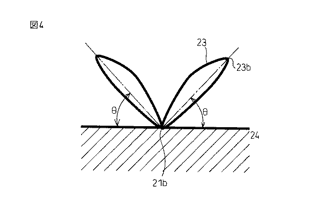
編地表面に対するループ糸の突出角度θの測定は、以下の方法による。なお、図4に示すように、地組織24表面の接線と、ループ糸23の経糸21との係合部(つまり、経糸の閉じ目21b)とループ糸先端部23bとを結んだ線分とのなす角度を「編地表面に対するループ糸の突出角度θ」と定義する。まず、編地20を、経糸21方向に対して垂直方向に切断し、地組織24面を平面に固定する。次いで、電子顕微鏡を用いて編地20の切断面の写真を撮影し、得られた写真から編地表面に対するループ糸の突出角度θを求める。
The loop thread protrusion angle θ with respect to the knitted fabric surface is measured by the following method. As shown in FIG. 4, the tangent line on the surface of the
編地20の編成に使用される編機としては、特に制限はなく、例えば、従来から広く用いられている3本筬や4本筬の編機をそのまま使用できる。したがって、本発明の面ファスナ雌材は、簡便且つ安価に生産することができる。
The knitting machine used for knitting the knitted
編地20を構成する経糸21、緯糸22、及びループ糸23の材質についても、特に制限はなく、ポリプロピレン、ポリエステル、ポリエチレン、ポリアミド、ポリウレタン、レーヨン、これらのコポリマー若しくは混合物、又は天然繊維等が挙げられる。ある態様においては、雄材との係合による雌材破壊を防ぐという観点から、高強度であるポリアミドが使用される。また、材料コストや環境安定性を考慮すれば、ポリエステルを使用することもできる。なお、ループ糸は、雄材との係合確率を高めるという点から、モノフィラメントよりマルチフィラメントのものを使用することが好ましい。この場合、ループ糸のフィラメントが細いと雄材との係合中に切れたりする場合があるので、面ファスナの形状等に基づき、適度な太さのものが選択される。経糸及び緯糸に関しては、モノフィラメントであっても、マルチフィラメントであってもよい。一般的には、フィラメント糸の繊度は、20〜220dtex、好ましくは20〜100dtexである。
The material of the
ある態様において、編地20は、1平方メートル当たり10〜100gの坪量を有することができる。坪量が10g/m2以下では編み立て時に編地としての形態保持が難しい場合があり、また100g/m2以上では剛性が増すことで、吸収性物品に取り付けられた時にその部分の柔軟性が損なわれる場合がある。また、編地が密となるため、基材上にデザインを施す場合には、その視認性が損なわれる場合がある。本発明の面ファスナ雌材10は、雄材との係合力に優れ、またその係合力の左右差が少ないため、従来品に比べて、坪量を小さくすることができる。そのため、視認性に優れた面ファスナ雌材を、安価に製造することが可能となる。
In some embodiments, the knitted
面ファスナ雌材10には、適宜、起毛、エンボス、印刷、染色、着色等の付加的加工を適用することができる。また、編地20は全体又は部分的に染められていてもよい。特に、おむつ等の吸収性物品の部材として使用する場合、艶、テカリといった光沢を無くすことができ、審美性に優れた外観を得ることができる。
Additional processing such as raising, embossing, printing, dyeing, and coloring can be applied to the surface fastener
基材30については、特に制限はなく、樹脂フィルム、不織布、紙、又はこれらの積層体等が使用できる。樹脂フィルムとしては、例えば、ポリプロピレン、ポリエチレン、ポリスチレン、ポリエチレンテレフタレートなどのポリエステル樹脂、ポリアミド樹脂、ポリウレタン樹脂などの合成樹脂フィルム、又はこれらの合成樹脂フィルムの積層フィルム等が挙げられる。また、ある態様においては、基材面に、雄材との係合面の位置指標や各種記号又はデザイン等を設けてもよい。
There is no restriction | limiting in particular about the
基材30は、表面からループ糸23が左右交互に突出している面と反対側の面で、編地20と接合している。基材30と編地20との接合方法については、特に制限はない。ドライラミネート、押し出しラミネート、ウェットラミネート、熱ラミネート、超音波等従来公知の方法を使用できる。中でも、生産性、柔軟性、基材層に設けられた位置指標等の視認性を考慮すると、ドライラミネート法が好適である。ドライラミネート用接着剤にはウレタン系、EVA系、アクリル系、酢酸ビニル系等、ウェットラミネート用接着剤には澱粉、カゼイン、酢酸ビニル、ポリアクリル酸エステル等の接着剤を使用でき、また押し出しラミネートにはポリエチレン、ポリプロピレン、あるいは変性ポリオレフィン等の樹脂を適宜使用することができる。ただし、これらの接着剤及び樹脂に限定されるものではない。
The
ドライラミネートの場合、接着剤層は、基材における一方の表面の全面に設けられてもよいし、また、部分的に設けられてもよい。接着剤層を部分的に設ける場合、その方法については特に制限はない。一般的には、接着剤のパターン塗布が用いられる。塗布のパターン、形状、サイズ等は、特に限定されず、円、楕円、四辺形、多角形など任意のパターン、形状、サイズを採用することができる。接着剤層を基材表面に部分的に設ける場合、編地を通して滲み出した接着剤によりループ糸の倒れる本数を少なくすることができ、それにより、雄材のフックとの係合力の低下を防止できる。さらに、パターンの形状や接着剤量を適切に設定することによって、係合力を変化させることが可能である。 In the case of dry lamination, the adhesive layer may be provided on the entire surface of one surface of the substrate, or may be provided partially. When the adhesive layer is partially provided, the method is not particularly limited. Generally, pattern application of an adhesive is used. The pattern, shape, size, etc. of application are not particularly limited, and any pattern, shape, size, such as a circle, ellipse, quadrilateral, or polygon can be employed. When the adhesive layer is partially provided on the surface of the base material, the number of loop yarns that fall due to the adhesive that has oozed through the knitted fabric can be reduced, thereby preventing a decrease in the engagement force with the hook of the male material. . Furthermore, the engagement force can be changed by appropriately setting the shape of the pattern and the amount of adhesive.
本発明の面ファスナ雌材10は、図5に示すように、雄材40と組み合わせることで面ファスナ50として使用される、ここで、面ファスナ雌材10の編地20に設けられたループ糸23(パイル)が、雄材40のフック41を受け入れることで、面ファスナ雌材10と雄材40とが係合し、固着される。本発明の面ファスナ雌材10を有する面ファスナ50においては、ループ糸23が編地20の一方の表面からのみ経糸21に対して左右交互に突出している構造を雌材が有しているため、雄材と係合した際、雄材との係合力の左右差が少ない。
As shown in FIG. 5, the surface fastener
ここで、係合力の左右差は、面ファスナ雌材を雄材に係合させ、幅方向(すなわち、CD方向、経糸方向に対して垂直方向)に対して、両者を右から左に剥離した際の係合力(右係合力)と左から右に剥離した際の係合力(左係合力)を複数点測定し、
{(測定された右係合力の平均値)−(測定された左係合力の平均値)}/(右係合力及び左係合力の全測定値の平均値)
を絶対値で表した数値を求めることで評価することができる。得られる数値が0に近いほど係合力の左右差が少ないことになる。
Here, the left-right difference in the engaging force is obtained when the surface fastener female material is engaged with the male material, and both are peeled from the right to the left in the width direction (that is, the direction perpendicular to the CD direction and the warp direction). Measure the engagement force (right engagement force) and the engagement force (left engagement force) when peeling from the left to the right.
{(Average value of measured right engagement force) − (average value of measured left engagement force)} / (average value of all measured values of right engagement force and left engagement force)
Can be evaluated by obtaining a numerical value representing the absolute value of. The closer the obtained value is to 0, the smaller the left-right difference in engagement force.
雄材としては、係合力を満足できるものであれば種類を問わないが、例えば、キノコ状、鍵状、J字状のフックを有する雄材を使用できる。雄材におけるピン密度は、特に指定はないが、1平方インチあたり500本から5000本程度が一般的であり、ある態様においては、1平方インチあたり1600本のピン密度のものが使用される。雄材の材料についても、雌材を構成する糸同様、ポリプロピレン、ポリエステル、ポリエチレン、ポリアミド、これらのコポリマー又は混合物等から選択できる。雄材の基材部分の厚さについても適宜設定可能である。具体的には、住友スリーエム社で市販されるフックテープ(CS−600)等が挙げられる。 The male material may be of any type as long as the engagement force can be satisfied. For example, a male material having a mushroom-shaped, key-shaped, or J-shaped hook can be used. The pin density in the male material is not particularly specified, but is generally about 500 to 5000 pins per square inch. In one aspect, a pin density of 1600 pins per square inch is used. The material of the male material can be selected from polypropylene, polyester, polyethylene, polyamide, copolymers or mixtures thereof as well as the yarn constituting the female material. The thickness of the base material portion of the male material can also be set as appropriate. Specifically, the hook tape (CS-600) etc. which are marketed by Sumitomo 3M are mentioned.
本発明の面ファスナは、床材や壁材の固定具、衣料の固定具、清掃用部材固定具、自動車内装材固定具等に使用できる。また、紙おむつ、生理用ナプキン、母乳パッド等の吸収性物品の固定具としても使用可能である。ここで、吸収性物品、特に紙おむつに面ファスナが用いられる場合、雌材と雄材との係合特性、特に雌材の性能に配慮する必要がある。通常の紙おむつにおいては、着用者の背側両側部に左右一対の雄材が設けられ、また、左右一対の雌材が前身ごろ腹部に設けられる。したがって、紙おむつの左右2箇所において雄材と雌材とがそれぞれ係合することになるが、この場合の係合力の左右差、すなわち左方向に剥離する力と右方向に剥離する力との差が大きくなると、着用者が面ファスナよる紙おむつの確実な固定機能に不安を感ずる場合がある。上述のとおり、本発明の雌材は、ループ糸が経糸に対して左右交互に突出している構造となっているため、雄材との係合力の左右差が少なく、好適である。 The hook-and-loop fastener of the present invention can be used for a flooring material or a wall material fixture, a clothing fixture, a cleaning member fixture, an automobile interior material fixture, or the like. It can also be used as a fixture for absorbent articles such as paper diapers, sanitary napkins, and breast milk pads. Here, when a surface fastener is used for an absorbent article, particularly a paper diaper, it is necessary to consider the engagement characteristics between the female material and the male material, particularly the performance of the female material. In a normal paper diaper, a pair of left and right male materials are provided on both sides of the wearer's back, and a pair of left and right female materials are provided on the front abdomen. Therefore, the male material and the female material are respectively engaged in the left and right two locations of the paper diaper. In this case, the difference between the left and right engagement forces, that is, the difference between the force that peels in the left direction and the force that peels in the right direction is the difference. When it becomes large, the wearer may feel anxious about the reliable fixing function of the disposable diaper by the hook-and-loop fastener. As described above, the female material of the present invention has a structure in which the loop yarn protrudes alternately to the left and right with respect to the warp yarn.
なお、本発明の面ファスナ雌材を吸収性物品の面ファスナに使用する場合、かかる吸収性物品への固定手段としては、例えばグルー、熱融着、超音波加工等による接着、一体成形、縫製、ステープラーによる機械的固定などを挙げることができる。グルーによる固定においてはSIS、SBS等のゴム系、アクリル系、シリコン系、EVA系等の公知の粘着剤が必要に応じて適宜選択されるが、これらの樹脂に限定されるものではない。 In addition, when using the surface fastener female material of the present invention for the surface fastener of an absorbent article, examples of fixing means to the absorbent article include adhesion by glue, heat fusion, ultrasonic processing, integral molding, and sewing. And mechanical fixing with a stapler. For fixing with glue, known adhesives such as SIS, SBS and other rubber-based, acrylic-based, silicon-based, and EVA-based adhesives are appropriately selected as necessary, but are not limited to these resins.
以下、本発明の実施例について更に詳細に説明するが、本発明はこれらの実施例に限定されるものではない。 Examples of the present invention will be described in detail below, but the present invention is not limited to these examples.
(実施例1)
3本筬編機(カールマイヤー社製)を用いて、トリコットパイル編みで、ループ糸1-0/3-4/6-7/4-3、縦糸1-0/0-1/0-1/1-0、緯糸0-0/3-3の編組織を有する編地を編成した。また、ループ糸、経糸、緯糸の材料としては、ループ糸:ポリアミド(78 Dtex、24本(東レ社製))、縦糸及び緯糸:ポリエステル(22 Dtex、1本(帝人社製))を使用した。編み条件としては、1 in 1 out(2針位置がWalesに対応)、Course 9.6/cm、Wales 5.5/cmとし、編地の坪量は21.8g/m2であった。
Example 1
Using a three-ply knitting machine (made by KARL MAYER), loop yarn 1-0 / 3-4 / 6-7 / 4-3, warp yarn 1-0 / 0-1 / 0-1 A knitted fabric having a knitting structure of / 1-0 and weft 0-0 / 3-3 was knitted. As materials for loop yarn, warp and weft, loop yarn: polyamide (78 Dtex, 24 (Toray Industries)), warp and weft: polyester (22 Dtex, 1 (Teijin)) were used. . The knitting conditions were 1 in 1 out (2 needle positions corresponding to Wales), Course 9.6 / cm, Wales 5.5 / cm, and the basis weight of the knitted fabric was 21.8 g / m 2 .
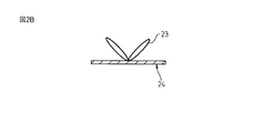
得られた編地を、12μm厚の二軸延伸ポリプロピレン基材(商品名:FOR2、フタムラ化学製(両面コロナ処理))に、ポリウレタン接着剤によりドライラミネートし、面ファスナ雌材を得た。得られた面ファスナ雌材の編地における編組織の模式図を図2Aに示す。また、図2Bは、図2AのA−A線に沿って(経糸方向に対して垂直方向)編地を切断した際に観察される、編地に形成されたループ糸の状態(左右1ループずつ)を示す模式図である。なお、接着剤の配合は、ポリウレタン主剤(商品名:タケラックA969v、三井化学ポリウレタン社製)、及びイソシアネート硬化剤(商品名:タケネートA5、三井化学ポリウレタン社製)に、シリカ(商品名:トクシールUSA、トクヤマ社製)を混合したものであり、シリカの量は、固形分比で、接着剤全量に対して8質量%である。具体的には、シリカを攪拌した溶剤に、ポリウレタン主剤及びイソシアネート硬化剤を加えて、更に攪拌した後、FUJISEIKI社製のドライラミネーターで150m/分でラミネートした。接着剤の塗布量は約5g/m2とした。 The obtained knitted fabric was dry laminated with a polyurethane adhesive on a 12 μm-thick biaxially stretched polypropylene base material (trade name: FOR2, manufactured by Futamura Chemical Co., Ltd. (double-sided corona treatment)) to obtain a face fastener female material. The schematic diagram of the knitting structure in the knitted fabric of the surface fastener female material obtained is shown in FIG. 2A. 2B shows the state of the loop yarn formed in the knitted fabric (one loop on the left and right sides) observed when the knitted fabric is cut along the line AA in FIG. 2A (perpendicular to the warp direction). FIG. The adhesive was blended into a polyurethane base (trade name: Takelac A969v, manufactured by Mitsui Chemicals Polyurethanes), an isocyanate curing agent (trade name: Takenate A5, manufactured by Mitsui Chemicals Polyurethanes), and silica (trade name: Toxeal USA). , Manufactured by Tokuyama Corporation), and the amount of silica is 8% by mass with respect to the total amount of the adhesive in terms of solid content ratio. Specifically, a polyurethane main agent and an isocyanate curing agent were added to a solvent in which silica was stirred, and the mixture was further stirred, and then laminated at 150 m / min with a dry laminator manufactured by FUJISEIKI. The amount of adhesive applied was about 5 g / m 2 .
(実施例2)
実施例1同様、3本筬編機(カールマイヤー社製)を用いて、トリコットパイル編みで、ループ糸1-0/3-4/6-7/4-3、縦糸1-0/0-1/0-1/1-0、緯糸0-0/3-3の編組織を有する編地を編成した。なお、ループ糸、経糸、緯糸の材料としては、ループ糸:ポリエステル(84 Dtex、36本(東レ社製))、縦糸及び緯糸:ポリエステル(22 Dtex、1本(帝人社製))を使用した。編み条件としては、1 in 1 out(2針位置がWalesに対応)、Course 10.4/cm、Wales 5.5/cmとし、編地の坪量は24.2g/m2であった。得られた編地を用い、実施例1と同様にして、面ファスナ雌材を得た。得られた面ファスナ雌材の編地における編組織の構造、及び編地に形成されたループ糸の状態は、実施例1と同様であった。
(Example 2)
As in Example 1, using a three-ply knitting machine (manufactured by KARL MAYER), tricot pile knitting, loop yarn 1-0 / 3-4 / 6-7 / 4-3, warp yarn 1-0 / 0- A knitted fabric having a knitting structure of 1 / 0-1 / 1-0 and weft 0-0 / 3-3 was knitted. As materials for loop yarn, warp and weft, loop yarn: polyester (84 Dtex, 36 (Toray Industries)), warp and weft: polyester (22 Dtex, 1 (Teijin)) were used. . The knitting conditions were 1 in 1 out (2 needle positions corresponding to Wales), Course 10.4 / cm, Wales 5.5 / cm, and the basis weight of the knitted fabric was 24.2 g / m 2 . Using the obtained knitted fabric, a surface fastener female material was obtained in the same manner as in Example 1. The structure of the knitted structure in the knitted fabric of the obtained surface fastener female material and the state of the loop yarn formed on the knitted fabric were the same as in Example 1.
(実施例3)
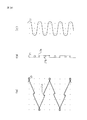
3本筬編機(カールマイヤー社製)を用いて、トリコットパイル編みで、ループ糸1-0/4-5/8-9/5-4、縦糸1-0/0-1/0-1/1-0、緯糸0-0/4-4の編組織を有する編地を編成した。また、ループ糸、経糸、緯糸の材料としては、ループ糸:ポリエステル(84 Dtex、36本(東レ社製))、縦糸及び緯糸:ポリエステル(22 Dtex、1本(帝人社製))を使用した。編み条件としては、1 in 2 out(3針位置がWalesに対応)、Course 10.4/cm、Wales 3.7/cmとし、編地の坪量は17.9g/m2であった。得られた編地を用い、実施例1と同様にして、面ファスナ雌材を得た。得られた面ファスナ雌材の編地における編組織の模式図を図6Aに、この編組織のパターンの模式図を図7に、それぞれ示す。また、図6Bは、図6AのB−B線に沿って(経糸方向に対して垂直方向)編地を切断した際に観察される、編地に形成されたループ糸の状態(左右1ループずつ)を示す模式図である。
(Example 3)
Using a three-ply knitting machine (made by KARL MAYER), loop yarn 1-0 / 4-5 / 8-9 / 5-4, warp 1-0 / 0-1 / 0-1 A knitted fabric having a knitting structure of / 1-0 and weft 0-0 / 4-4 was knitted. In addition, as a material for loop yarn, warp and weft, loop yarn: polyester (84 Dtex, 36 (Toray Industries)), warp and weft: polyester (22 Dtex, 1 (Teijin)) was used. . The knitting conditions were 1 in 2 out (3 needle positions corresponding to Wales), Course 10.4 / cm, Wales 3.7 / cm, and the basis weight of the knitted fabric was 17.9 g / m 2 . Using the obtained knitted fabric, a surface fastener female material was obtained in the same manner as in Example 1. A schematic diagram of the knitting structure in the knitted fabric of the obtained surface fastener female material is shown in FIG. 6A, and a schematic diagram of the pattern of the knitting structure is shown in FIG. 6B shows the state of the loop yarn formed in the knitted fabric (one loop on the left and right sides) observed when the knitted fabric is cut along the line BB in FIG. 6A (perpendicular to the warp direction). FIG.
(比較例1)
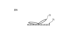
ポリアミド製で、編地の坪量が22g/m2である編地を用い、実施例1と同様にして、面ファスナ雌材を得た。図8は、得られた面ファスナにおいて、編地の経糸方向に対して垂直方向に編地を切断した際に観察される、編地に形成されたループ糸の状態(左右1ループずつ)を示す模式図である。
(Comparative Example 1)
A face fastener female material was obtained in the same manner as in Example 1 using a knitted fabric made of polyamide and having a basis weight of 22 g / m 2 . FIG. 8 shows the state of the loop yarn formed on the knitted fabric (one loop on each side) observed when the knitted fabric is cut in a direction perpendicular to the warp direction of the knitted fabric in the obtained surface fastener. It is a schematic diagram shown.
(比較例2)
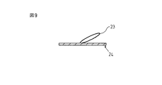
ポリエステル製で、編地の坪量が26.5g/m2である編地を用い、実施例1と同様にして、面ファスナ雌材を得た。図9は、得られた面ファスナにおいて、編地の経糸方向に対して垂直方向に編地を切断した際に観察される、編地に形成されたループ糸の状態を示す模式図である。図9から理解されるように、比較例2の面ファスナにおいては、ループ糸は左右両方向ではなく片方向にのみ形成されている。
(Comparative Example 2)
A face fastener female material was obtained in the same manner as in Example 1 using a knitted fabric made of polyester and having a basis weight of 26.5 g / m 2 . FIG. 9 is a schematic diagram showing a state of the loop yarn formed on the knitted fabric observed when the knitted fabric is cut in a direction perpendicular to the warp direction of the knitted fabric in the obtained surface fastener. As understood from FIG. 9, in the surface fastener of the comparative example 2, the loop yarn is formed only in one direction, not in both the left and right directions.
(面ファスナ雌材の評価)
(係合力)
上記実施例及び比較例で得られた面ファスナ雌材の上に、25mm幅の雄材(CS−600、住友スリーエム社製)を乗せて、2kgのローラで圧着した。次いで、雌材と雄材とを水平に1kgの力で引っ張り、両者を係合させた。係合した面ファスナ雌材と雄材とを、垂直方向に引張り速度300mm/分で引っ張って、剥離するときの剥離力を測定して、係合力(N/25mm)を求めた。なお、係合力は、係合した雌材及び雄材を、幅方向(すなわち、CD方向、経糸方向に対して垂直方向)に対して、右から左に剥離した際の係合力(右係合力)、及び左から右に剥離した際の係合力(左係合力)を各6点ずつ測定し、この全12点の平均値として求めた。結果を表1に示す。
(Evaluation of female surface fastener)
(Engagement force)
A 25 mm wide male material (CS-600, manufactured by Sumitomo 3M Limited) was placed on the surface fastener female material obtained in the above-described Examples and Comparative Examples, and pressure-bonded with a 2 kg roller. Next, the female material and the male material were pulled horizontally with a force of 1 kg to engage them. The engaged surface fastener female material and male material were pulled in the vertical direction at a pulling speed of 300 mm / min, and the peeling force when peeling was measured to determine the engaging force (N / 25 mm). The engagement force is the engagement force (right engagement force) when the engaged female material and male material are peeled from the right to the left in the width direction (that is, the direction perpendicular to the CD direction and the warp direction). And, the engaging force (left engaging force) at the time of peeling from the left to the right was measured 6 points each, and the average value of all 12 points was obtained. The results are shown in Table 1.
(係合力方向性)
上記のように測定された右係合力及び左係合力の各測定値から、下記式に従い、
{(6点測定された右係合力の平均値)−(6点測定された左係合力の平均値)}/(右係合力と左係合力との全測定値(12点)の平均値)
を絶対値で表した数値を求め、係合力方向性とした。得られた数値が0に近いほど係合力の左右差が少ないことになる。結果を表1に示す。
(Direction of engagement force)
From each measurement value of the right engagement force and the left engagement force measured as described above, according to the following formula:
{(Average value of right engagement force measured at 6 points) − (Average value of left engagement force measured at 6 points)} / (Average value of all measured values (12 points) of right engagement force and left engagement force) )
Was obtained as an absolute value and used as the engaging force directionality. The closer the obtained value is to 0, the smaller the left-right difference in engagement force. The results are shown in Table 1.
(ループ糸突出角度)
図4に示すように、地組織表面の接線と、ループ糸の経糸との係合部とループ糸先端部とを結んだ線分とのなす角度を「編地表面に対するループ糸の突出角度θ」と定義した。まず、編地を、経糸方向に対して垂直方向に切断し、地組織24面を平面に固定した。次いで、電子顕微鏡を用いて編地切断面の写真を撮影し、得られた写真から編地表面に対するループ糸の突出角度を左右各5点ずつ(合わせて10点)(比較例2は片方向のみ5点)測定した。実施例1〜3においては、ループ糸の突出角度における左右差がなかったため、全測定値(10点)の平均値を求めた。比較例1についてはループ糸突出角度の左右それぞれの測定値の平均値を、比較例2は片方向のみのループ糸突出角度の平均値を、それぞれ求めた。結果を表1に示す。
(Loop thread protrusion angle)
As shown in FIG. 4, the angle formed by the tangent line on the surface of the ground structure and the line segment connecting the engaging portion of the loop yarn warp and the tip of the loop yarn is expressed by “the projection angle θ of the loop yarn with respect to the surface of the knitted fabric”. Defined. First, the knitted fabric was cut in a direction perpendicular to the warp direction, and the
(層間強度)
接着剤で接着された面ファスナ雌材の編地と基材を、チャック間25mmにセットし、垂直方向に引張り速度300mm/分で引っ張って、編地と基材とが剥離するときの力を、テンシロン引張試験機を用いて測定し、層間強度(N/25mm)とした。結果を表1に示す。
(Interlayer strength)
Set the surface knitted fabric knitted fabric and base material bonded with adhesive to 25 mm between the chucks, and pull the knitted fabric from the base material at a pulling speed of 300 mm / min. The tensile strength was measured using a Tensilon tensile tester to obtain the interlayer strength (N / 25 mm). The results are shown in Table 1.
10 面ファスナ雌材
20 編地
21 経糸
21a 経糸における開き目
21b 経糸における閉じ目
22 緯糸
23 ループ糸
23a ループ糸における開き目
23b ループ糸先端部
24 地組織
30 基材
40 雄材
41 フック
50 面ファスナ
DESCRIPTION OF
Claims (4)
経糸は、開き目と閉じ目を交互に繰り返す鎖編糸からなり、
ループ糸は、ループ糸の開き目のみに経糸の閉じ目のみが係合して、経糸と固定されており、
ループ糸は編地の一方の表面からのみ、経糸に対して左右交互に突出している、
面ファスナ雌材。 A knitted fabric composed of warp, weft, and loop yarn, and a surface fastener female material including a base material,
The warp consists of chain knitting yarn that repeats the opening and closing alternately,
The loop yarn is fixed to the warp with only the opening of the loop yarn engaging only the closing of the warp,
The loop yarn protrudes alternately from the left and right with respect to the warp yarn only from one surface of the knitted fabric.
Face fastener female material.
Priority Applications (7)
| Application Number | Priority Date | Filing Date | Title |
|---|---|---|---|
| JP2008232543A JP5384888B2 (en) | 2008-09-10 | 2008-09-10 | Face fastener female material |
| PCT/US2009/055817 WO2010030548A2 (en) | 2008-09-10 | 2009-09-03 | Female part of hook and loop fastener |
| CN2009801355041A CN102149297B (en) | 2008-09-10 | 2009-09-03 | Female part of hook and loop fastener |
| BRPI0913527A BRPI0913527A2 (en) | 2008-09-10 | 2009-09-03 | "female part of a hook and loop fastener" |
| EP09813464.6A EP2334213A4 (en) | 2008-09-10 | 2009-09-03 | Female part of hook and loop fastener |
| KR1020117007815A KR20110059868A (en) | 2008-09-10 | 2009-09-03 | Female part of hook and loop fastener |
| US13/061,407 US20120010588A1 (en) | 2008-09-10 | 2009-09-03 | Female part of hook and loop fastener |
Applications Claiming Priority (1)
| Application Number | Priority Date | Filing Date | Title |
|---|---|---|---|
| JP2008232543A JP5384888B2 (en) | 2008-09-10 | 2008-09-10 | Face fastener female material |
Publications (2)
| Publication Number | Publication Date |
|---|---|
| JP2010063633A true JP2010063633A (en) | 2010-03-25 |
| JP5384888B2 JP5384888B2 (en) | 2014-01-08 |
Family
ID=42005706
Family Applications (1)
| Application Number | Title | Priority Date | Filing Date |
|---|---|---|---|
| JP2008232543A Expired - Fee Related JP5384888B2 (en) | 2008-09-10 | 2008-09-10 | Face fastener female material |
Country Status (7)
| Country | Link |
|---|---|
| US (1) | US20120010588A1 (en) |
| EP (1) | EP2334213A4 (en) |
| JP (1) | JP5384888B2 (en) |
| KR (1) | KR20110059868A (en) |
| CN (1) | CN102149297B (en) |
| BR (1) | BRPI0913527A2 (en) |
| WO (1) | WO2010030548A2 (en) |
Cited By (5)
| Publication number | Priority date | Publication date | Assignee | Title |
|---|---|---|---|---|
| WO2012017830A1 (en) * | 2010-08-06 | 2012-02-09 | 丸紅インテックス株式会社 | Knitted fabric for hook-and-loop fastener |
| JP2012034802A (en) * | 2010-08-06 | 2012-02-23 | Three M Innovative Properties Co | Female part of hook and loop fastener |
| CN102560831A (en) * | 2010-12-14 | 2012-07-11 | 无锡百和织造股份有限公司 | Transparent rough-surface magic tape |
| JP2016087065A (en) * | 2014-11-04 | 2016-05-23 | スリーエム イノベイティブ プロパティズ カンパニー | Touch fastener female material, touch fastener, and absorbent article |
| JP2020006021A (en) * | 2018-07-11 | 2020-01-16 | スリーエム イノベイティブ プロパティズ カンパニー | Manufacturing method of knitted fabric for hook-and-loop fastener female material, knitted fabric for hook-and-loop fastener female material, and hook-and-loop fastener female material |
Families Citing this family (15)
| Publication number | Priority date | Publication date | Assignee | Title |
|---|---|---|---|---|
| EP2439323B1 (en) * | 2010-10-08 | 2018-07-04 | Mondi Gronau GmbH | Compound material element for a hook-and-loop fastener |
| US8833829B2 (en) * | 2011-07-08 | 2014-09-16 | Inteva Products Llc | Method for stitching vehicle interior components and components formed from the method |
| US9809176B2 (en) | 2011-07-08 | 2017-11-07 | Inteva Products, Llc | Method for stitching vehicle interior components and components formed from the method |
| US9340912B2 (en) | 2011-07-08 | 2016-05-17 | Inteva Products, Llc | Method for stitching vehicle interior components and components formed from the method |
| CN103649397B (en) | 2011-07-08 | 2016-05-25 | 因特瓦产品有限责任公司 | For making the device of vehicle interior part |
| ITBO20110484A1 (en) * | 2011-08-03 | 2013-02-04 | Magis S P A | MULTILAYERED MATERIAL AND PROCEDURE FOR THE CONSTRUCTION OF A MULTILAYERED MATERIAL |
| US9119443B2 (en) * | 2011-08-25 | 2015-09-01 | Velcro Industries B.V. | Loop-engageable fasteners and related systems and methods |
| JP6006731B2 (en) * | 2011-12-14 | 2016-10-12 | クラレファスニング株式会社 | Loop hook-and-loop fastener with excellent alignment function |
| WO2014113811A1 (en) * | 2013-01-21 | 2014-07-24 | Kleen Maid, Inc. | Wipe pad for mop heads |
| DE102013010085A1 (en) * | 2013-06-10 | 2014-12-11 | Gottlieb Binder Gmbh & Co. Kg | Flat adhesive closure part and cleaning system with such a sheet-like adhesive closure part |
| JP2015119782A (en) * | 2013-12-20 | 2015-07-02 | スリーエム イノベイティブ プロパティズ カンパニー | Fixing member for hook-and-loop fastener, manufacturing method thereof, and sanitary article |
| JP6509506B2 (en) * | 2014-07-09 | 2019-05-08 | スリーエム イノベイティブ プロパティズ カンパニー | Loop members for surface fasteners and sanitary products |
| JP6774738B2 (en) | 2015-04-15 | 2020-10-28 | スリーエム イノベイティブ プロパティズ カンパニー | Hook-and-loop female material, hook-and-loop fastener, and absorbent articles |
| JP2017169616A (en) * | 2016-03-18 | 2017-09-28 | スリーエム イノベイティブ プロパティズ カンパニー | Surface fastener member and method for manufacturing the same |
| US10582743B2 (en) | 2016-03-21 | 2020-03-10 | Delphini, Llc | System and method for activated interlocking fasteners and seals |
Citations (4)
| Publication number | Priority date | Publication date | Assignee | Title |
|---|---|---|---|---|
| JPH0860503A (en) * | 1994-07-25 | 1996-03-05 | Milliken Res Corp | Knitted fabric |
| JPH09291452A (en) * | 1996-04-22 | 1997-11-11 | New Nitto:Kk | Warp knit fabric containing lame |
| JP2002253305A (en) * | 2001-03-05 | 2002-09-10 | Kurashiki Seni Kako Kk | Loop material for surface fastener and its knitting method |
| JP2005118360A (en) * | 2003-10-17 | 2005-05-12 | Ykk Corp | Female member of hook and loop fastener |
Family Cites Families (11)
| Publication number | Priority date | Publication date | Assignee | Title |
|---|---|---|---|---|
| JPH0437453Y2 (en) * | 1987-03-24 | 1992-09-03 | ||
| JP2563369Y2 (en) * | 1992-09-21 | 1998-02-18 | ワイケイケイ株式会社 | Warp knit base fabric for hook-and-loop fastener |
| JPH0652521U (en) * | 1992-12-28 | 1994-07-19 | 吉田工業株式会社 | Male fastening material for hook-and-loop fasteners with high-density hook pieces |
| CN1149033C (en) * | 1995-07-26 | 2004-05-12 | 可乐丽股份有限公司 | Hook-and-loop fastener female material |
| JP3425501B2 (en) * | 1995-12-22 | 2003-07-14 | ワイケイケイ株式会社 | Hook-and-loop fastener |
| US5996189A (en) * | 1998-03-30 | 1999-12-07 | Velcro Industries B.V. | Woven fastener product |
| FR2791707B1 (en) * | 1999-03-30 | 2001-05-25 | Aplix Sa | KNITTED FABRIC WITH LOW GRAMMING LOOPS |
| US6855220B2 (en) * | 2002-08-05 | 2005-02-15 | Tietex International, Ltd. | Fastener fabric and related method |
| JP3895272B2 (en) * | 2002-12-24 | 2007-03-22 | Ykk株式会社 | Fiber hook and loop fastener |
| JP4480333B2 (en) * | 2003-02-07 | 2010-06-16 | スリーエム イノベイティブ プロパティズ カンパニー | Face fastener female material |
| TWI358285B (en) * | 2004-07-02 | 2012-02-21 | 3M Innovative Properties Co | Knitted loop tape, hook and loop fastening system, |
-
2008
- 2008-09-10 JP JP2008232543A patent/JP5384888B2/en not_active Expired - Fee Related
-
2009
- 2009-09-03 EP EP09813464.6A patent/EP2334213A4/en not_active Withdrawn
- 2009-09-03 KR KR1020117007815A patent/KR20110059868A/en not_active Application Discontinuation
- 2009-09-03 US US13/061,407 patent/US20120010588A1/en not_active Abandoned
- 2009-09-03 CN CN2009801355041A patent/CN102149297B/en not_active Expired - Fee Related
- 2009-09-03 WO PCT/US2009/055817 patent/WO2010030548A2/en active Application Filing
- 2009-09-03 BR BRPI0913527A patent/BRPI0913527A2/en not_active IP Right Cessation
Patent Citations (4)
| Publication number | Priority date | Publication date | Assignee | Title |
|---|---|---|---|---|
| JPH0860503A (en) * | 1994-07-25 | 1996-03-05 | Milliken Res Corp | Knitted fabric |
| JPH09291452A (en) * | 1996-04-22 | 1997-11-11 | New Nitto:Kk | Warp knit fabric containing lame |
| JP2002253305A (en) * | 2001-03-05 | 2002-09-10 | Kurashiki Seni Kako Kk | Loop material for surface fastener and its knitting method |
| JP2005118360A (en) * | 2003-10-17 | 2005-05-12 | Ykk Corp | Female member of hook and loop fastener |
Cited By (10)
| Publication number | Priority date | Publication date | Assignee | Title |
|---|---|---|---|---|
| WO2012017830A1 (en) * | 2010-08-06 | 2012-02-09 | 丸紅インテックス株式会社 | Knitted fabric for hook-and-loop fastener |
| JP2012034832A (en) * | 2010-08-06 | 2012-02-23 | Marubeni Intex Co Ltd | Knitted fabric for hook-and-loop fastener |
| JP2012034802A (en) * | 2010-08-06 | 2012-02-23 | Three M Innovative Properties Co | Female part of hook and loop fastener |
| KR101189688B1 (en) | 2010-08-06 | 2012-10-10 | 마루하 타테아미 가부시키가이샤 | Knitted Fabric for Hook-and-Loop fastener |
| US8713974B2 (en) | 2010-08-06 | 2014-05-06 | Marubeni Intex Co., Ltd. | Knitted fabric for hook-and-loop fastener |
| CN102560831A (en) * | 2010-12-14 | 2012-07-11 | 无锡百和织造股份有限公司 | Transparent rough-surface magic tape |
| JP2016087065A (en) * | 2014-11-04 | 2016-05-23 | スリーエム イノベイティブ プロパティズ カンパニー | Touch fastener female material, touch fastener, and absorbent article |
| US10709620B2 (en) | 2014-11-04 | 2020-07-14 | 3M Innovative Properties Company | Touch fastener female material, touch fastener, and absorbent article |
| JP2020006021A (en) * | 2018-07-11 | 2020-01-16 | スリーエム イノベイティブ プロパティズ カンパニー | Manufacturing method of knitted fabric for hook-and-loop fastener female material, knitted fabric for hook-and-loop fastener female material, and hook-and-loop fastener female material |
| JP7126394B2 (en) | 2018-07-11 | 2022-08-26 | スリーエム イノベイティブ プロパティズ カンパニー | Method for manufacturing knitted fabric for female material of hook-and-loop fastener, knitted fabric for female material of hook-and-loop fastener, and female material of hook-and-loop fastener |
Also Published As
| Publication number | Publication date |
|---|---|
| CN102149297A (en) | 2011-08-10 |
| JP5384888B2 (en) | 2014-01-08 |
| KR20110059868A (en) | 2011-06-07 |
| WO2010030548A2 (en) | 2010-03-18 |
| CN102149297B (en) | 2013-09-18 |
| WO2010030548A3 (en) | 2010-07-01 |
| US20120010588A1 (en) | 2012-01-12 |
| BRPI0913527A2 (en) | 2015-11-24 |
| EP2334213A2 (en) | 2011-06-22 |
| EP2334213A4 (en) | 2013-08-07 |
Similar Documents
| Publication | Publication Date | Title |
|---|---|---|
| JP5384888B2 (en) | Face fastener female material | |
| JP5841318B2 (en) | Hook fastener | |
| JP6033540B2 (en) | Composite elements for hook and loop fasteners | |
| WO2015095525A1 (en) | Fastening member for hook-and-loop fastener and method for manufacturing the same, and sanitary product | |
| JP6563636B2 (en) | Female hook-and-loop fastener, hook-and-loop fastener, and absorbent article | |
| TWM320855U (en) | Silence-type plane buckle | |
| JP2005253667A (en) | Female member of hook-and-loop fastener | |
| JP6774738B2 (en) | Hook-and-loop female material, hook-and-loop fastener, and absorbent articles | |
| JP4480333B2 (en) | Face fastener female material | |
| JP2008088602A (en) | Engaging female member of hook-and-loop fastener | |
| WO2020012333A2 (en) | Knitted fabric for hook and loop fastener and method for manufacturing | |
| CN103343421B (en) | Fabric and the goods comprising fabric | |
| JP3098436B2 (en) | Velcro fastener female material |
Legal Events
| Date | Code | Title | Description |
|---|---|---|---|
| A621 | Written request for application examination |
Free format text: JAPANESE INTERMEDIATE CODE: A621 Effective date: 20110811 |
|
| A977 | Report on retrieval |
Free format text: JAPANESE INTERMEDIATE CODE: A971007 Effective date: 20121011 |
|
| A131 | Notification of reasons for refusal |
Free format text: JAPANESE INTERMEDIATE CODE: A131 Effective date: 20121023 |
|
| A601 | Written request for extension of time |
Free format text: JAPANESE INTERMEDIATE CODE: A601 Effective date: 20130123 |
|
| A602 | Written permission of extension of time |
Free format text: JAPANESE INTERMEDIATE CODE: A602 Effective date: 20130128 |
|
| TRDD | Decision of grant or rejection written | ||
| A01 | Written decision to grant a patent or to grant a registration (utility model) |
Free format text: JAPANESE INTERMEDIATE CODE: A01 Effective date: 20130903 |
|
| A61 | First payment of annual fees (during grant procedure) |
Free format text: JAPANESE INTERMEDIATE CODE: A61 Effective date: 20131003 |
|
| R150 | Certificate of patent or registration of utility model |
Free format text: JAPANESE INTERMEDIATE CODE: R150 |
|
| LAPS | Cancellation because of no payment of annual fees |