JP2010062933A - Relay server, and relayed communication system - Google Patents
Relay server, and relayed communication system Download PDFInfo
- Publication number
- JP2010062933A JP2010062933A JP2008227231A JP2008227231A JP2010062933A JP 2010062933 A JP2010062933 A JP 2010062933A JP 2008227231 A JP2008227231 A JP 2008227231A JP 2008227231 A JP2008227231 A JP 2008227231A JP 2010062933 A JP2010062933 A JP 2010062933A
- Authority
- JP
- Japan
- Prior art keywords
- relay server
- information
- relay
- client terminal
- communication
- Prior art date
- Legal status (The legal status is an assumption and is not a legal conclusion. Google has not performed a legal analysis and makes no representation as to the accuracy of the status listed.)
- Granted
Links
Images


Abstract
Description
本発明は、遠隔のLAN(Local Area Network)に接続されるクライアント端末が、WAN(Wide Area Network)を超えて通信することを可能にする中継サーバおよび中継通信システムに関する。 The present invention relates to a relay server and a relay communication system that enable a client terminal connected to a remote LAN (Local Area Network) to communicate over a WAN (Wide Area Network).
遠隔のLANに接続されるクライアント端末が、WANを超えて通信することがある。VPN(Virtual Private Network)は、遠隔のLANが直接に接続されているかのようなネットワークを構築できる。しかし、VPNは、拡張性および柔軟性のあるネットワークを構築することが困難である。 A client terminal connected to a remote LAN may communicate over a WAN. A VPN (Virtual Private Network) can construct a network as if a remote LAN is directly connected. However, it is difficult for VPN to build a scalable and flexible network.
特許文献1が開示する中継通信システムは、VPNと同様に、遠隔のLANが直接に接続されているかのようなネットワークを構築できる。そして、中継通信システムは、VPNと異なり、拡張性および柔軟性のあるネットワークを構築することが容易である。
The relay communication system disclosed in
中継通信システムは、WAN、複数のLANを備える。各LANは、中継サーバを備える。各中継サーバは、中継通信システムが備える中継サーバについての中継グループ情報、中継通信システムが共有するリソースについての共有リソース情報を格納する。 The relay communication system includes a WAN and a plurality of LANs. Each LAN includes a relay server. Each relay server stores relay group information about a relay server included in the relay communication system and shared resource information about a resource shared by the relay communication system.
一のLANに接続されるクライアント端末が、他のLANに接続されるクライアント端末が格納するリソースを操作するときには、これらのLANに接続される中継サーバは、中継グループ情報および共有リソース情報に基づいて、リソースの操作を中継する。 When a client terminal connected to one LAN operates a resource stored in a client terminal connected to another LAN, the relay server connected to these LANs is based on the relay group information and the shared resource information. , Relay resource operations.
中継通信システムが備えるLANが増減することがある。中継通信システムが共有するリソースが更新されることがある。しかし、中継通信システムは、これらの変化に対応して、中継グループ情報および共有リソース情報を更新できる。そして、中継通信システムは、これらの変化に対応して、拡張性および柔軟性のあるネットワークを構築できる。 The number of LANs included in the relay communication system may increase or decrease. Resources shared by the relay communication system may be updated. However, the relay communication system can update the relay group information and the shared resource information in response to these changes. And the relay communication system can construct | assemble a network with an expandability and flexibility corresponding to these changes.
特許文献1が開示する中継通信システムにおいて、一のLANに接続されるクライアント端末は、他のLANに接続されるクライアント端末と以下のように通信を実行する。
In the relay communication system disclosed in
最初の区間として、一のLANに接続されるクライアント端末および中継サーバの相互間において、通信が開始する。中間の区間として、一のLANおよび他のLANに接続される中継サーバの相互間において、通信が中継される。最後の区間として、他のLANに接続される中継サーバおよびクライアント端末の相互間において、通信が終了する。 As the first section, communication starts between the client terminal connected to one LAN and the relay server. As an intermediate section, communication is relayed between relay servers connected to one LAN and another LAN. As the last section, communication ends between the relay server and the client terminal connected to another LAN.
最初および最後の区間における通信は、LAN内における通信である。そのため、プライベートIP(Internet Protocol)アドレスが利用されるIPv4(Internet Protocol version 4)通信が採用されることが多い。また、非暗号通信が採用されることが多い。 Communication in the first and last section is communication within the LAN. For this reason, IPv4 (Internet Protocol version 4) communication using a private IP (Internet Protocol) address is often adopted. Non-encrypted communication is often employed.
中間の区間における通信は、WAN内における通信である。そのため、IPアドレスが枯渇化しないIPv6(Internet Protocol version 6)通信が採用されることがある。また、暗号通信が採用されることがある。 Communication in the middle section is communication within the WAN. Therefore, IPv6 (Internet Protocol version 6) communication that does not deplete IP addresses may be employed. In addition, encryption communication may be employed.
各区間における通信方式を統一方式にするときには、以上のように柔軟性のある運用を図れない。各区間における通信方式を独立方式にするときには、以上のように柔軟性のある運用を図れるが、柔軟性のある運用を容易にする手段は開示されていない。 When the communication method in each section is unified, flexible operation as described above cannot be achieved. When the communication method in each section is an independent method, flexible operation can be achieved as described above, but means for facilitating flexible operation is not disclosed.
そこで、本発明は前記問題点に鑑み、遠隔のLANに接続されるクライアント端末がWANを超えて通信することを可能にする中継通信システムにおいて、各区間における通信方式を独立方式にする柔軟性のある運用を容易にする手段を提供することを目的とする。 In view of the above problems, the present invention is a relay communication system that enables a client terminal connected to a remote LAN to communicate over a WAN. The purpose is to provide a means for facilitating certain operations.
上記課題を解決するため、請求項1記載の発明は、第1ネットワークに接続される第1中継サーバと通信可能であり、第2ネットワークに接続される第2中継サーバとして機能する中継サーバであって、前記第1中継サーバと前記第2中継サーバが中継グループを構成することを示す中継グループ情報を作成する中継グループ情報作成部と、前記第1中継サーバの起動状態を示す第1中継サーバ起動情報と、前記第1中継サーバと前記第1ネットワークに接続される第1クライアント端末との間の接続状態を含め前記第1中継サーバに登録されている前記第1クライアント端末に関する第1クライアント端末登録情報と、を含み、前記第1中継サーバが作成する第1中継サーバ情報と、前記第2中継サーバの起動状態を示す第2中継サーバ起動情報と、前記第2中継サーバと前記第2ネットワークに接続される第2クライアント端末との間の接続状態を含め前記第2中継サーバに登録されている前記第2クライアント端末に関する第2クライアント端末登録情報と、を含み、前記第2中継サーバが作成する第2中継サーバ情報と、を含む中継サーバ情報と、前記中継グループ情報とを、前記第1中継サーバと前記第2中継サーバとの間で共有する中継サーバ間共有部と、前記中継グループ情報と前記中継サーバ情報とを前記第2中継サーバと前記第2クライアント端末との間で共有するクライアント端末間共有部と、前記中継グループ情報と前記中継サーバ情報に基づいて選択された宛先に対する、前記第2中継サーバが中継する通信を実行する通信実行部と、を備え、前記通信実行部は、前記第2ネットワーク内の端末を宛先とする通信と、前記第1ネットワーク内の端末を宛先とする通信とでは、異なる通信方式を設定可能であり、前記通信実行部は、前記宛先として指定された識別情報と、前記中継グループ情報と前記中継サーバ情報に記載された識別情報と、を照合することにより、転送先を決定する転送先決定部と、前記転送先に基づいて前記転送先に対する通信方式を決定する通信方式決定部と、を含むことを特徴とする。
In order to solve the above problem, the invention according to
請求項2記載の発明は、請求項1に記載の中継サーバにおいて、前記通信方式決定部は、前記転送先と前記転送先に対するアドレス設定方式とを対応付けるアドレス設定情報を作成するアドレス設定情報作成部と、前記転送先と前記アドレス設定情報とに基づいて、前記転送先に対するアドレス設定方式を決定するアドレス設定方式決定部と、を含むことを特徴とする。 According to a second aspect of the present invention, in the relay server according to the first aspect, the communication method determining unit generates an address setting information for associating the transfer destination with an address setting method for the transfer destination. And an address setting method determining unit that determines an address setting method for the transfer destination based on the transfer destination and the address setting information.
請求項3記載の発明は、請求項1または請求項2に記載の中継サーバにおいて、前記通信方式決定部は、前記転送先と前記転送先に対する暗号通信方式とを対応付ける暗号通信設定情報を作成する暗号通信設定情報作成部と、前記転送先と前記暗号通信設定情報とに基づいて、前記転送先に対する暗号通信設定方式を決定する暗号通信設定方式決定部と、を含むことを特徴とする。 According to a third aspect of the present invention, in the relay server according to the first or second aspect, the communication method determining unit creates encrypted communication setting information that associates the transfer destination with an encrypted communication method for the transfer destination. An encryption communication setting information generation unit; and an encryption communication setting method determination unit that determines an encryption communication setting method for the transfer destination based on the transfer destination and the encryption communication setting information.
請求項4記載の発明は、第1ネットワークと、第2ネットワークと、前記第1ネットワークに接続される第1中継サーバと、前記第2ネットワークに接続される第2中継サーバと、を備える中継通信システムであって、前記第1中継サーバと前記第2中継サーバとは、前記第1中継サーバと前記第2中継サーバとが中継グループを構成することを示す中継グループ情報を作成する中継グループ情報作成部、を含み、前記第1中継サーバは、前記第1中継サーバの起動状態を示す第1中継サーバ起動情報と、前記第1中継サーバと前記第1ネットワークに接続される第1クライアント端末との間の接続状態を含め前記第1中継サーバに登録されている前記第1クライアント端末に関する第1クライアント端末登録情報と、を含む第1中継サーバ情報を作成する第1中継サーバ情報作成部、を含み、前記第2中継サーバは、前記第2中継サーバの起動状態を示す第2中継サーバ起動情報と、前記第2中継サーバと前記第2ネットワークに接続される第2クライアント端末との間の接続状態を含め前記第2中継サーバに登録されている前記第2クライアント端末に関する第2クライアント端末登録情報と、を含む第2中継サーバ情報を作成する第2中継サーバ情報作成部、を含み、前記第1中継サーバと前記第2中継サーバとは、前記第1中継サーバ情報と前記第2中継サーバ情報と、を含む中継サーバ情報と、前記中継グループ情報とを、前記第1中継サーバと前記第2中継サーバとの間で共有する中継サーバ間共有部、を含み、前記第1中継サーバは、前記中継グループ情報と前記中継サーバ情報とを前記第1中継サーバと前記第1クライアント端末との間で共有する第1クライアント端末間共有部、を含み、前記第2中継サーバは、前記中継グループ情報と前記中継サーバ情報とを前記第2中継サーバと前記第2クライアント端末との間で共有する第2クライアント端末間共有部、を含み、前記第1中継サーバは、前記中継グループ情報と前記中継サーバ情報とに基づいて選択された宛先に対する、前記第1中継サーバが中継する通信を実行する通信実行部、を含み、前記通信実行部は、前記第2ネットワーク内の端末を宛先とする通信と、前記第1ネットワーク内の端末を宛先とする通信とでは、異なる通信方式を設定可能であり、前記通信実行部は、前記宛先として指定された識別情報と、前記中継グループ情報と前記中継サーバ情報とに記載された識別情報と、を照合することにより、転送先を決定する転送先決定部と、前記転送先に基づいて前記転送先に対する通信方式を決定する通信方式決定部と、を含むことを特徴とする。 The invention according to claim 4 is a relay communication comprising a first network, a second network, a first relay server connected to the first network, and a second relay server connected to the second network. The first relay server and the second relay server are relay systems that create relay group information indicating that the first relay server and the second relay server constitute a relay group. The first relay server includes: first relay server activation information indicating an activation state of the first relay server; and a first client terminal connected to the first relay server and the first network. First client terminal registration information relating to the first client terminal registered in the first relay server including a connection state between the first relay server and the first relay server A first relay server information creating unit for creating a report, wherein the second relay server includes second relay server activation information indicating an activation state of the second relay server, the second relay server, and the second network. Second relay server information including second client terminal registration information related to the second client terminal registered in the second relay server, including a connection state with the second client terminal connected to A second relay server information creating unit, wherein the first relay server and the second relay server include the relay server information including the first relay server information and the second relay server information, and the relay group An inter-relay server sharing unit that shares information between the first relay server and the second relay server, the first relay server including the relay group information and the medium A first inter-client-terminal sharing unit that shares server information between the first relay server and the first client terminal, wherein the second relay server includes the relay group information and the relay server information. A second inter-client-terminal sharing unit that is shared between the second relay server and the second client terminal, wherein the first relay server is selected based on the relay group information and the relay server information A communication execution unit that executes communication relayed by the first relay server to the destination, the communication execution unit configured to communicate with a terminal in the second network and a terminal in the first network. Different communication methods can be set, and the communication execution unit can identify the identification information designated as the destination, the relay group information, and the A transfer destination determination unit that determines a transfer destination by collating the identification information described in the relay server information; a communication method determination unit that determines a communication method for the transfer destination based on the transfer destination; It is characterized by including.
請求項5記載の発明は、請求項4に記載の中継通信システムにおいて、前記通信方式決定部は、前記転送先と前記転送先に対するアドレス設定方式とを対応付けるアドレス設定情報を作成するアドレス設定情報作成部と、前記転送先と前記アドレス設定情報とに基づいて、前記転送先に対するアドレス設定方式を決定するアドレス設定方式決定部と、を含むことを特徴とする。 According to a fifth aspect of the present invention, in the relay communication system according to the fourth aspect, the communication method determination unit generates address setting information for associating the transfer destination with an address setting method for the transfer destination. And an address setting method determination unit that determines an address setting method for the transfer destination based on the transfer destination and the address setting information.
請求項6記載の発明は、請求項4または請求項5に記載の中継通信システムにおいて、前記通信方式決定部は、前記転送先と前記転送先に対する暗号通信方式とを対応付ける暗号通信設定情報を作成する暗号通信設定情報作成部と、前記転送先と前記暗号通信設定情報とに基づいて、前記転送先に対する暗号通信設定方式を決定する暗号通信設定方式決定部と、を含むことを特徴とする。 According to a sixth aspect of the present invention, in the relay communication system according to the fourth or fifth aspect, the communication method determination unit creates encrypted communication setting information that associates the transfer destination with an encrypted communication method for the transfer destination. And an encryption communication setting information determination unit that determines an encryption communication setting method for the transfer destination based on the transfer destination and the encryption communication setting information.
中継通信システムは、第1ネットワークおよび第2ネットワークを備える。第1ネットワークは、第1中継サーバおよび第1クライアント端末を備える。第2ネットワークは、第2中継サーバおよび第2クライアント端末を備える。第1中継サーバおよび第2中継サーバは、第1クライアント端末および第2クライアント端末の相互間の通信を中継する。 The relay communication system includes a first network and a second network. The first network includes a first relay server and a first client terminal. The second network includes a second relay server and a second client terminal. The first relay server and the second relay server relay communication between the first client terminal and the second client terminal.
第1(第2)中継サーバは、中継グループ情報、第1(第2)中継サーバ情報、クライアント端末情報を作成する。中継グループ情報は、第1中継サーバおよび第2中継サーバが中継グループを構成することを示す情報である。第1(第2)中継サーバ情報は、第1(第2)中継サーバと通信可能である第1(第2)クライアント端末を示す情報である。クライアント端末情報は、第1(第2)クライアント端末の第1(第2)ネットワークにおける接続環境を示す情報である。 The first (second) relay server creates relay group information, first (second) relay server information, and client terminal information. The relay group information is information indicating that the first relay server and the second relay server constitute a relay group. The first (second) relay server information is information indicating a first (second) client terminal that can communicate with the first (second) relay server. The client terminal information is information indicating a connection environment of the first (second) client terminal in the first (second) network.
第1(第2)中継サーバは、中継グループ情報を参照することにより、第1中継サーバ情報および第2中継サーバ情報を、第1中継サーバおよび第2中継サーバの相互間において共有できる。第1(第2)中継サーバは、各々のクライアント端末情報を参照することにより、中継グループ情報および中継サーバ情報を、第1(第2)中継サーバおよび第1(第2)クライアント端末の相互間において共有できる。 The first (second) relay server can share the first relay server information and the second relay server information between the first relay server and the second relay server by referring to the relay group information. The first (second) relay server refers to each client terminal information so that the relay group information and the relay server information can be obtained between the first (second) relay server and the first (second) client terminal. Can share.
第1(第2)中継サーバは、中継グループ情報および中継サーバ情報に基づいて選択された宛先に対する、第1(第2)中継サーバが中継する通信を実行する。第1(第2)中継サーバは、宛先として指定された識別情報を、中継グループ情報および中継サーバ情報に記載された識別情報と照合することにより、転送先を決定する。第1(第2)中継サーバは、転送先に基づいて、アドレス設定方式および暗号通信設定方式など、転送先に対する通信方式を決定する。中継通信システムは、各区間における通信方式を独立方式にする、柔軟性のある運用を容易に図ることができる。 The first (second) relay server executes communication relayed by the first (second) relay server to the destination selected based on the relay group information and the relay server information. The first (second) relay server determines the transfer destination by comparing the identification information designated as the destination with the identification information described in the relay group information and the relay server information. The first (second) relay server determines a communication method for the transfer destination, such as an address setting method and an encryption communication setting method, based on the transfer destination. The relay communication system can easily achieve flexible operation in which the communication method in each section is an independent method.
{中継通信システムの全体構成}
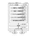
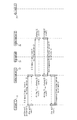
以下、図面を参照しつつ、本発明の実施の形態について説明する。図1は、中継通信システムの全体構成を示す図である。中継通信システムは、LAN1、2、WAN3から構成される。LAN1、2は、遠隔に構築される小規模なネットワークである。WAN3は、インターネットなどの大規模なネットワークである。
{Overall configuration of relay communication system}
Hereinafter, embodiments of the present invention will be described with reference to the drawings. FIG. 1 is a diagram illustrating an overall configuration of a relay communication system. The relay communication system includes
LAN1は、クライアント端末11、中継サーバ12から構成される。LAN2は、クライアント端末21、中継サーバ22から構成される。WAN3は、SIP(Session Initiation Protocol)サーバ31から構成される。
The
クライアント端末11、21は、パーソナルコンピュータなどである。中継サーバ12、22は、クライアント端末11、21の相互間の通信を中継する。SIPサーバ31は、中継サーバ12、22の相互間の通信を中継する。
The
本実施の形態においては、中継サーバ12、22の相互間の通信プロトコルとして、SIPを利用するが、SIP以外のプロトコルを利用してもよい。SIP以外のプロトコルを利用するときには、中継サーバ12、22の相互間の通信が直接に実行されればよい。
In the present embodiment, SIP is used as a communication protocol between the
クライアント端末11および中継サーバ12の相互間の通信として、IPv4通信および非暗号通信が採用される。中継サーバ12および中継サーバ22の相互間の通信として、IPv6通信および暗号通信が採用される。クライアント端末21および中継サーバ22の相互間の通信として、IPv4通信および非暗号通信が採用される。
As communication between the
{中継サーバの構成要素}
図2は、中継サーバ12(22)の構成要素を示す図である。中継サーバ12(22)は、インターフェース部121(221)、制御部122(222)、データベース格納部123(223)から構成される。括弧が付されていない符号は、中継サーバ12における符号を示す。括弧が付されている符号は、中継サーバ22における符号を示す。
{Components of relay server}
FIG. 2 is a diagram showing components of the relay server 12 (22). The relay server 12 (22) includes an interface unit 121 (221), a control unit 122 (222), and a database storage unit 123 (223). A code without parentheses indicates a code in the
インターフェース部121(221)は、IPv4通信におけるプライベートIPアドレスを利用して、LAN1(2)に接続されるクライアント端末11(21)に対して通信を実行する。インターフェース部121(221)は、IPv6通信におけるIPアドレスを利用して、WAN3に接続されるSIPサーバ31に対して通信を実行する。
The interface unit 121 (221) performs communication with the client terminal 11 (21) connected to the LAN 1 (2) using a private IP address in IPv4 communication. The interface unit 121 (221) performs communication with the
制御部122(222)は、クライアント端末11、21の相互間の通信を中継するための制御を実行する。制御部122(222)は、データベース格納部123(223)に格納される中継グループ情報、中継サーバ情報、クライアント端末情報を作成または更新する。制御部122(222)は、データベース格納部123(223)に格納されるネットワーク設定情報、暗号通信設定情報を作成する。
The control unit 122 (222) executes control for relaying communication between the
データベース格納部123(223)は、中継グループ情報格納部124(224)、中継サーバ情報格納部125(225)、クライアント端末情報格納部126(226)、ネットワーク設定情報格納部127(227)、暗号通信設定情報格納部128(228)から構成される。以上の情報について以下に説明する。 The database storage unit 123 (223) includes a relay group information storage unit 124 (224), a relay server information storage unit 125 (225), a client terminal information storage unit 126 (226), a network setting information storage unit 127 (227), an encryption It is comprised from the communication setting information storage part 128 (228). The above information will be described below.
{中継グループ情報の具体例}
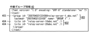
図3は、中継グループ情報の具体例として、中継グループ情報40を示す図である。中継グループ情報は、中継通信システムを構成する中継サーバの概要を示す情報である。
{Specific example of relay group information}
FIG. 3 is a diagram illustrating the relay group information 40 as a specific example of the relay group information. The relay group information is information indicating an outline of the relay server that constitutes the relay communication system.
中継グループ情報40は、上位情報401、下位情報402から構成される。上位情報401は、中継グループ識別情報403を含む。下位情報402は、中継サーバ識別情報404を含む。
The relay group information 40 includes
上位情報401は、上位にある中継グループについての情報である。中継グループ識別情報403は、図1に示した中継グループを識別する情報である。「lastmod」は、中継グループ情報の最新更新時刻を示す。「name」は、中継グループの名称を示す。
The
下位情報402は、下位にある中継サーバについての情報である。中継サーバ識別情報404は、中継サーバを識別する情報である。
The
中継グループ情報40は、中継グループ情報格納部124、224において格納される。すなわち、中継グループ情報40は、中継サーバ12、22により共有される。さらに、中継グループ情報40は、中継サーバ12、22およびクライアント端末11、21により共有される。
The relay group information 40 is stored in the relay group
{中継サーバ情報の具体例}
図4は、中継サーバ情報の具体例として、中継サーバ情報50を示す図である。中継サーバ情報は、中継通信システムを構成する中継サーバの詳細を示す情報であり、中継通信システムを構成するクライアント端末の概要を示す情報である。
{Specific example of relay server information}
FIG. 4 is a diagram illustrating the relay server information 50 as a specific example of the relay server information. The relay server information is information that indicates details of the relay server that constitutes the relay communication system, and is an information that indicates an outline of the client terminal that constitutes the relay communication system.
中継サーバ情報50は、上位情報501−1、501−2、下位情報502−1、502−2から構成される。上位情報501−1、501−2は、各々、中継サーバ識別情報503−1、503−2、中継サーバ起動情報504−1、504−2を含む。下位情報502−1、502−2は、各々、中継グループ識別情報505−1、505−2、クライアント端末識別情報506−1、506−2、クライアント端末が中継サーバにログインしているかどうかを示すクライアント端末サイト情報507−1、507−2を含む。 The relay server information 50 includes upper information 501-1 and 501-2 and lower information 502-1 and 502-2. The upper information 501-1 and 501-2 include relay server identification information 503-1 and 503-2, and relay server activation information 504-1 and 504-2, respectively. The lower information 502-1 and 502-2 indicate relay group identification information 505-1 and 505-2, client terminal identification information 506-1 and 506-2, and whether the client terminal is logged in to the relay server, respectively. Client terminal site information 507-1 and 507-2 are included.
上位情報501−1、501−2は、上位にある中継サーバについての情報である。中継サーバ識別情報503−1、503−2は、中継サーバを識別する情報である。「name」は、中継サーバの名称を示す。中継サーバ起動情報504−1、504−2は、中継サーバが起動しているかどうかについての情報である。 The upper information 501-1 and 501-2 are information on the relay server at the upper level. The relay server identification information 503-1 and 503-2 are information for identifying the relay server. “Name” indicates the name of the relay server. The relay server activation information 504-1 and 504-2 are information about whether the relay server is activated.
下位情報502−1、502−2は、下位にあるクライアント端末についての情報である。「div」は、クライアント端末の部署名を示す。中継グループ識別情報505−1、505−2は、図1に示した中継グループを識別する情報である。クライアント端末識別情報506−1、506−2は、クライアント端末を識別する情報である。「name」は、クライアント端末の名称を示す。クライアント端末サイト情報507−1、507−2は、クライアント端末がログオンしている中継サーバの識別情報を示す。 The lower information 502-1 and 502-2 are information about the lower client terminals. “Div” indicates a department name of the client terminal. The relay group identification information 505-1 and 505-2 are information for identifying the relay group shown in FIG. The client terminal identification information 506-1 and 506-2 are information for identifying the client terminal. “Name” indicates the name of the client terminal. Client terminal site information 507-1 and 507-2 indicate identification information of the relay server to which the client terminal is logged on.
中継サーバ情報50は、中継サーバ情報格納部125、225において格納される。すなわち、中継サーバ情報50は、中継サーバ12、22により共有される。さらに、中継サーバ情報50は、中継サーバ12、22およびクライアント端末11、21により共有される。
The relay server information 50 is stored in the relay server
中継サーバが起動しているときには、中継サーバ起動情報504−1、504−2が「active」になっている。中継サーバが起動していないときには、中継サーバ起動情報504−1、504−2が空欄になっている。これにより、中継サーバが起動しているかどうかについての情報が、中継通信システム全体として共有される。 When the relay server is activated, the relay server activation information 504-1 and 504-2 are “active”. When the relay server is not activated, the relay server activation information 504-1 and 504-2 are blank. Thereby, information about whether the relay server is activated is shared as the whole relay communication system.
クライアント端末が中継サーバにログオンしているときには、クライアント端末サイト情報507−1、507−2が記載されている。クライアント端末が中継サーバにログオンしていないときには、クライアント端末サイト情報507−1、507−2が記載されていない。これにより、クライアント端末が中継サーバにログオンしているかどうかについての情報が、中継通信システム全体として共有される。 When the client terminal is logged on to the relay server, client terminal site information 507-1 and 507-2 are described. When the client terminal is not logged on to the relay server, the client terminal site information 507-1 and 507-2 are not described. As a result, information about whether the client terminal is logged on to the relay server is shared as the entire relay communication system.
{クライアント端末情報の具体例}
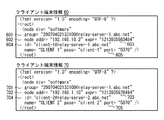
図5は、クライアント端末情報の具体例として、クライアント端末情報60、70を示す図である。クライアント端末情報は、中継通信システムを構成するクライアント端末の詳細を示す情報である。
{Specific examples of client terminal information}
FIG. 5 is a diagram showing client terminal information 60 and 70 as specific examples of the client terminal information. The client terminal information is information indicating details of the client terminals that constitute the relay communication system.
クライアント端末情報60、70は、各々、中継グループ識別情報601、701、クライアント端末アドレス情報602、702、クライアント端末有効期限情報603、703、クライアント端末識別情報604、704、クライアント端末ポート情報605、705を含む。
The client terminal information 60 and 70 are relay
「div」は、クライアント端末の部署名を示す。中継グループ識別情報601、701は、図1に示した中継グループを識別する情報である。クライアント端末アドレス情報602、702は、クライアント端末のIPアドレスを示す。クライアント端末有効期限情報603、703は、クライアント端末のレジスト有効期限を示す。クライアント端末識別情報604、704は、クライアント端末を識別する情報である。「name」は、クライアント端末の名称を示す。「pass」は、クライアント端末のパスワードを示す。クライアント端末ポート情報605、705は、クライアント端末のポート番号を示す。
“Div” indicates a department name of the client terminal. The relay
クライアント端末情報60は、クライアント端末情報格納部126のみにおいて格納されて、クライアント端末情報70は、クライアント端末情報格納部226のみにおいて格納される。すなわち、クライアント端末情報60は、中継サーバ12のみにより保有されて、クライアント端末情報70は、中継サーバ22のみにより保有される。
The client terminal information 60 is stored only in the client terminal
{ネットワーク設定情報}
図6は、中継サーバ12がネットワーク設定情報格納部127において格納する、ネットワーク設定情報81を示す図である。WAN側設定情報811は、図1に示したように、中継サーバ12および中継サーバ22の相互間において、IPv6通信が採用されることを示す。LAN側設定情報812は、図1に示したように、クライアント端末11および中継サーバ12の相互間において、IPv4通信が採用されることを示す。
{Network setting information}
FIG. 6 is a diagram showing the network setting information 81 stored in the network setting
WAN側設定情報811について説明する。中継サーバ12のIPv6通信におけるIPアドレスとして、「2001:222:1002:2000::5」が設定されている。シグナリングポートとして「5060」が、セキュアシグナリングポートとして「5062」が、セッションポートとして「5070」が設定されている。
The WAN side setting information 811 will be described. As an IP address in the IPv6 communication of the
LAN側設定情報812について説明する。中継サーバ12のIPv4通信におけるプライベートIPアドレスとして、「192.168.10.1」が設定されている。IPv4通信が採用されることに伴って、サブネットマスクとして「255.255.255.0」が、DNS(Domain Name Server)アドレスとして「192.168.10.3」が、ゲートウェイアドレスとして「192.168.10.3」が設定されている。シグナリングポートとして「5060」が、セキュアシグナリングポートとして「5062」が、セッションポートとして「5070」が設定されている。
The LAN side setting information 812 will be described. As the private IP address in the IPv4 communication of the
図7は、中継サーバ22がネットワーク設定情報格納部227において格納する、ネットワーク設定情報82を示す図である。WAN側設定情報821は、図1に示したように、中継サーバ12および中継サーバ22の相互間において、IPv6通信が採用されることを示す。LAN側設定情報822は、図1に示したように、クライアント端末21および中継サーバ22の相互間において、IPv4通信が採用されることを示す。
FIG. 7 is a diagram showing the network setting information 82 stored in the network setting
WAN側設定情報821について説明する。中継サーバ22のIPv6通信におけるIPアドレスとして、「2001:222:1002:2000::6」が設定されている。シグナリングポートとして「5060」が、セキュアシグナリングポートとして「5062」が、セッションポートとして「5070」が設定されている。
The WAN side setting information 821 will be described. As the IP address in the IPv6 communication of the
LAN側設定情報822について説明する。中継サーバ22のIPv4通信におけるプライベートIPアドレスとして、「192.168.1.1」が設定されている。IPv4通信が採用されることに伴って、サブネットマスクとして「255.255.255.0」が、DNS(Domain Name Server)アドレスとして「192.168.1.2」が、ゲートウェイアドレスとして「192.168.1.2」が設定されている。シグナリングポートとして「5060」が、セキュアシグナリングポートとして「5062」が、セッションポートとして「5070」が設定されている。
The LAN side setting information 822 will be described. “192.168.1.1” is set as a private IP address in the IPv4 communication of the
送信側が受信側にWAN3を超えてデータを送信するときには、受信側のIPアドレスを宛先として指定することなく、受信側の識別情報を宛先として指定する。
When the transmission side transmits data to the reception side over
中継サーバ12、22は、宛先として指定された受信側の識別情報を確認する。そして、中継サーバ12、22は、中継グループ情報、中継サーバ情報、クライアント端末情報を参照することにより、データを転送する中継サーバを決定する。そして、中継サーバ12、22は、ネットワーク設定情報を参照することにより、データを転送する中継サーバに対応する通信方式として、IPv4通信またはIPv6通信を採用する。
The
{暗号通信設定情報}
図8は、中継サーバ12が暗号通信設定情報格納部128において格納する、暗号通信設定情報91を示す図である。WAN側設定情報911は、図1に示したように、中継サーバ12および中継サーバ22の相互間において、暗号通信が採用されることを示す。LAN側設定情報912は、図1に示したように、クライアント端末11および中継サーバ12の相互間において、非暗号通信が採用されることを示す。
{Encryption communication setting information}
FIG. 8 is a diagram showing the encrypted communication setting information 91 stored in the encrypted communication setting
WAN側設定情報911について説明する。暗号通信が採用されることを示す情報として、「ON」が設定されている。暗号通信が採用されることに伴って、認証サーバとして「1001:118:0f02:1000::165」が、認証IDとして「4347834957YHD」が、認証パスワードとして「orKgHD5e3344A」が、ユーザ名として「relay−server−1@abc.net」が、認証サーバシグナリングポートとして「5060」が、認証サーバセキュアシグナリングポートとして「5062」が設定されている。 The WAN side setting information 911 will be described. “ON” is set as information indicating that encrypted communication is employed. With the adoption of encryption communication, “1001: 118: 0f02: 1000 :: 165” as the authentication server, “4347384957YHD” as the authentication ID, “orKgHD5e3344A” as the authentication password, and “relay−” as the user name “server-1@abc.net” is set with “5060” as the authentication server signaling port and “5062” as the authentication server secure signaling port.
LAN側設定情報912について説明する。非暗号通信が採用されることを示す情報として、「OFF」が設定されている。非暗号通信が採用されることに伴って、認証サーバ、認証ID、認証パスワード、ユーザ名、認証サーバシグナリングポート、認証サーバセキュアシグナリングポートについての設定項目は空欄になっている。 The LAN side setting information 912 will be described. “OFF” is set as information indicating that non-encrypted communication is employed. Along with the adoption of non-encrypted communication, setting items for the authentication server, authentication ID, authentication password, user name, authentication server signaling port, and authentication server secure signaling port are blank.
図9は、中継サーバ22が暗号通信設定情報格納部228において格納する、暗号通信設定情報92を示す図である。WAN側設定情報921は、図1に示したように、中継サーバ12および中継サーバ22の相互間において、暗号通信が採用されることを示す。LAN側設定情報922は、図1に示したように、クライアント端末21および中継サーバ22の相互間において、非暗号通信が採用されることを示す。
FIG. 9 is a diagram showing encrypted communication setting information 92 stored in the encrypted communication setting
WAN側設定情報921について説明する。暗号通信が採用されることを示す情報として、「ON」が設定されている。暗号通信が採用されることに伴って、認証サーバとして「1001:118:0f02:1000::165」が、認証IDとして「4347834957XYZ」が、認証パスワードとして「orKgHD5e1234B」が、ユーザ名として「relay−server−2@abc.net」が、TCP通信における認証サーバシグナリングポートとして「5060」が、認証サーバセキュアシグナリングポートとして「5062」が設定されている。 The WAN side setting information 921 will be described. “ON” is set as information indicating that encrypted communication is employed. With the adoption of encryption communication, “1001: 118: 0f02: 1000 :: 165” as the authentication server, “43474834957XYZ” as the authentication ID, “orKgHD5e1234B” as the authentication password, and “relay−” as the user name In “server-2@abc.net”, “5060” is set as the authentication server signaling port in TCP communication, and “5062” is set as the authentication server secure signaling port.
LAN側設定情報922について説明する。非暗号通信が採用されることを示す情報として、「OFF」が設定されている。非暗号通信が採用されることに伴って、認証サーバ、認証ID、認証パスワード、ユーザ名、認証サーバシグナリングポート、認証サーバセキュアシグナリングポートについての設定項目は空欄になっている。 The LAN side setting information 922 will be described. “OFF” is set as information indicating that non-encrypted communication is employed. Along with the adoption of non-encrypted communication, setting items for the authentication server, authentication ID, authentication password, user name, authentication server signaling port, and authentication server secure signaling port are blank.
送信側が受信側にWAN3を超えてデータを送信するときには、受信側のIPアドレスを宛先として指定することなく、受信側の識別情報を宛先として指定する。
When the transmission side transmits data to the reception side over
中継サーバ12、22は、宛先として指定された受信側の識別情報を確認する。そして、中継サーバ12、22は、中継グループ情報、中継サーバ情報、クライアント端末情報を参照することにより、データを転送する相手方を決定する。さらに、中継サーバ12、22は、暗号通信設定情報を参照することにより、データを転送する相手方に対する通信方式として、暗号通信または非暗号通信を採用する。
The
{情報共有の流れ}
図10は、中継グループ情報、中継サーバ情報が共有される処理の流れを示す図である。中継サーバ12、22が、中継通信システムに参加する。クライアント端末11のユーザが、中継サーバ12にログオンして、クライアント端末21のユーザが、中継サーバ22にログオンする。
{Information sharing flow}
FIG. 10 is a diagram illustrating a flow of processing in which relay group information and relay server information are shared. The
[ステップS1からステップS2までの処理の流れ]
中継サーバ12の管理者および中継サーバ22の管理者は、LAN1、2の相互間において中継通信システムのグループを構築する契約を結ぶ。
[Processing flow from step S1 to step S2]
The administrator of the
中継サーバ12の管理者および中継サーバ22の管理者は、各々、WAN側設定情報811およびWAN側設定情報821の記載内容を決定する。制御部122および制御部222は、各々、WAN側設定情報811およびWAN側設定情報821を作成して、ネットワーク設定情報格納部127およびネットワーク設定情報格納部227に格納する。
The administrator of the
中継サーバ12の管理者および中継サーバ22の管理者は、各々、WAN側設定情報911およびWAN側設定情報921の記載内容を決定する。制御部122および制御部222は、各々、WAN側設定情報911およびWAN側設定情報921を作成して、暗号通信設定情報格納部128および暗号通信設定情報格納部228に格納する。
The administrator of the
中継サーバ12の管理者は、クライアント端末11のユーザに対して、アカウントを作成する(ステップS1:CreateAccount())。制御部122は、中継サーバ情報51−1を作成して、中継サーバ情報格納部125に格納する。
The administrator of the
中継サーバ12の管理者は、LAN側設定情報812およびLAN側設定情報912の記載内容を決定する。制御部122は、LAN側設定情報812およびLAN側設定情報912を作成して、各々、ネットワーク設定情報格納部127および暗号通信設定情報格納部128に格納する。
The administrator of the
中継サーバ22の管理者は、クライアント端末21のユーザに対して、アカウントを作成する(ステップS2:CreateAccount())。制御部222は、中継サーバ情報51−2を作成して、中継サーバ情報格納部225に格納する。
The administrator of the
中継サーバ22の管理者は、LAN側設定情報822およびLAN側設定情報922の記載内容を決定する。制御部222は、LAN側設定情報822およびLAN側設定情報922を作成して、各々、ネットワーク設定情報格納部227および暗号通信設定情報格納部228に格納する。
The administrator of the
以上の処理の流れにより、中継サーバ12は、中継サーバ情報51−1、ネットワーク設定情報81、暗号通信設定情報91を保有する。中継サーバ22は、中継サーバ情報51−2、ネットワーク設定情報82、暗号通信設定情報92を保有する。
Through the above processing flow, the
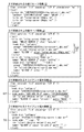
図11の1番目の枠内は、中継サーバ情報51−1を示す。上位情報511−1は、上位にある中継サーバ12についての情報である。中継サーバ識別情報513−1として、「relay−server−1@abc.net」が設定されている。「name」として、「RELAY SERVER 1」が設定されている。中継サーバ起動情報514−1として、「active」が設定されている。すなわち、中継サーバ12は、起動している。
The first frame in FIG. 11 shows the relay server information 51-1. The upper information 511-1 is information about the
下位情報512−1は、下位にあるクライアント端末11についての情報である。「div」として、「software」が設定されている。中継グループ識別情報515−1として、「20070402133100@relay−server−1.abc.net」が設定されている。クライアント端末識別情報516−1として、「client−1@relay−server−1.abc.net」が設定されている。「name」として、「CLIENT 1」が設定されている。クライアント端末サイト情報517−1は、空欄になっている。すなわち、クライアント端末11のユーザは、中継サーバ12にログオンしていない。
The lower information 512-1 is information about the
図11の2番目の枠内は、中継サーバ情報51−2を示す。上位情報511−2は、上位にある中継サーバ22についての情報である。中継サーバ識別情報513−2として、「relay−server−2@abc.net」が設定されている。「name」として、「RELAY SERVER 2」が設定されている。中継サーバ起動情報514−2として、「active」が設定されている。すなわち、中継サーバ22は、起動している。
The second frame in FIG. 11 shows the relay server information 51-2. The upper information 511-2 is information about the
下位情報512−2は、下位にあるクライアント端末21についての情報である。「div」として、「software」が設定されている。中継グループ識別情報515−2として、「20070402133100@relay−server−1.abc.net」が設定されている。クライアント端末識別情報516−2として、「client−2@relay−server−2.abc.net」が設定されている。「name」として、「CLIENT 2」が設定されている。クライアント端末サイト情報517−2は、空欄になっている。すなわち、クライアント端末21のユーザは、中継サーバ22にログオンしていない。
The lower information 512-2 is information about the
[ステップS3からステップS4までの処理の流れ]
以下の説明においては、中継サーバ12、22の相互間の通信は、SIPサーバ31により中継される。中継サーバ12(22)が中継サーバ22(12)に対してSIPサーバ31を介して通信を実行する方法について説明する。
[Processing flow from step S3 to step S4]
In the following description, communication between the
中継サーバ12(22)は、SIPサーバ31に対して、中継サーバ22(12)のアカウントが通信先として指定されたデータなどを送信する。SIPサーバ31は、中継サーバ12、22のアカウントを、各々、中継サーバ12、22のIPv6通信におけるIPアドレスに対応付けている。SIPサーバ31は、中継サーバ22(12)のアカウントに基づいて、中継サーバ22(12)のIPv6通信におけるIPアドレスを取得する。SIPサーバ31は、中継サーバ22(12)に対して、中継サーバ22(12)のIPv6通信におけるIPアドレスが通信先として指定されたデータなどを送信する。
The relay server 12 (22) transmits, for example, data in which the account of the relay server 22 (12) is designated as a communication destination to the
中継サーバ12は、中継サーバ22に対して、中継通信システムのグループ構築を要求する(ステップS3:SetGroup())。制御部122は、中継グループ情報42を作成して、中継グループ情報格納部124に格納する。制御部222は、中継グループ情報42を作成して、中継グループ情報格納部224に格納する。
The
中継サーバ12は、中継サーバ22に対して、中継サーバ情報の交換を要求する(ステップS4:exchange(db))。中継サーバ12は、中継サーバ22に対して、中継サーバ情報51−1の複製を送信する。中継サーバ22は、中継サーバ12に対して、中継サーバ情報51−2の複製を送信する。
The
制御部122は、中継サーバ情報51−2の複製、中継サーバ情報51−1を合成することにより、中継サーバ情報52を作成して、中継サーバ情報格納部125に格納する。制御部222は、中継サーバ情報51−1の複製、中継サーバ情報51−2を合成することにより、中継サーバ情報52を作成して、中継サーバ情報格納部225に格納する。
The
制御部122は、クライアント端末情報62を作成して、クライアント端末情報格納部126に格納する。制御部222は、クライアント端末情報72を作成して、クライアント端末情報格納部226に格納する。クライアント端末情報62の作成処理および格納処理は、ステップS1において実行され、クライアント端末情報72の作成処理および格納処理は、ステップS2において実行され。
The
以上の処理の流れにより、中継サーバ12は、中継グループ情報42、中継サーバ情報52、クライアント端末情報62を保有する。中継サーバ22は、中継グループ情報42、中継サーバ情報52、クライアント端末情報72を保有する。中継グループ情報42、中継サーバ情報52は、中継サーバ12、22により共有されている。
Through the above processing flow, the
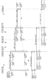
図12の1番目の枠内は、中継グループ情報42を示す。上位情報421は、上位にある中継グループについての情報である。中継グループ識別情報423として、「20070402133100@relay−server−1.abc.net」が設定されている。「lastmod」として、「20070402133100」が設定されている。「name」として、「GROUP 1」が設定されている。
The first frame in FIG. 12 shows the relay group information 42. The
下位情報422は、下位にある中継サーバ12、22についての情報である。中継サーバ識別情報424として、「relay−server−1@abc.net」、「relay−server−2@abc.net」が設定されている。
The
図12の2番目の枠内は、中継サーバ情報52を示す。上位情報521−1、521−2は、各々、図11の上位情報511−1、511−2と同様である。下位情報522−1、522−2は、各々、図11の下位情報512−1、512−2と同様である。
The second frame in FIG. 12 shows the
図12の3番目の枠内は、クライアント端末情報62を示す。「div」として、「software」が設定されている。中継グループ識別情報621として、「20070402133100@relay−server−1.abc.net」が設定されている。クライアント端末識別情報624として、「client−1@relay−server−1.abc.net」が設定されている。「name」として、「CLIENT 1」が設定されている。「pass」として、「client−1」が設定されている。
The third frame in FIG. 12 shows
クライアント端末アドレス情報622は、空欄になっている。クライアント端末有効期限情報623として、「0」が設定されている。クライアント端末ポート情報625は、空欄になっている。すなわち、クライアント端末11のユーザは、中継サーバ12にログオンしていない。
The client
図12の4番目の枠内は、クライアント端末情報72を示す。「div」として、「software」が設定されている。中継グループ識別情報721として、「20070402133100@relay−server−1.abc.net」が設定されている。クライアント端末識別情報724として、「client−2@relay−server−2.abc.net」が設定されている。「name」として、「CLIENT 2」が設定されている。「pass」として、「client−2」が設定されている。
The fourth frame in FIG. 12 shows
クライアント端末アドレス情報722は、空欄になっている。クライアント端末有効期限情報723として、「0」が設定されている。クライアント端末ポート情報725は、空欄になっている。すなわち、クライアント端末21のユーザは、中継サーバ22にログオンしていない。
The client
[ステップS5からステップS7までの処理の流れ]
クライアント端末11のユーザは、クライアント端末11の識別情報として、「client−1@relay−server−1.abc.net」を入力して、クライアント端末11のパスワードとして、「client−1」を入力する。クライアント端末11のユーザは、中継サーバ12にログオンする(ステップS5:REGISTER(ID,PASS))。制御部122は、クライアント端末情報62を参照することにより、クライアント端末11のユーザの認証を実行する。
[Processing flow from step S5 to step S7]
The user of the
制御部122は、クライアント端末11のユーザのログオンを受け付ける。制御部122は、中継サーバ情報52を更新することにより、中継サーバ情報53を作成して、中継サーバ情報格納部125に格納する。制御部122は、クライアント端末情報62を更新することにより、クライアント端末情報63を作成して、クライアント端末情報格納部126に格納する。制御部122は、中継グループ情報42を更新することはない。
The
クライアント端末11は、中継サーバ12に対して、中継グループ情報および中継サーバ情報の提供を要求する(ステップS6:get())。中継サーバ12は、クライアント端末11に対して、中継グループ情報42および中継サーバ情報53の複製を送信する。クライアント端末11は、中継グループ情報42、中継サーバ情報53を格納する。
The
制御部122は、中継グループ情報42、中継サーバ情報53を参照することにより、中継サーバ情報52が中継サーバ情報53に更新されたことを通知すべき中継サーバを決定する。制御部122は、中継サーバ情報53の中継サーバ起動情報534−2が「active」である中継サーバ22を、通知すべき中継サーバとして決定する。
The
中継サーバ12は、中継サーバ22に対して、中継サーバ情報52が中継サーバ情報53に更新されたことを通知する(ステップ7:NOTIFY())。制御部222は、中継サーバ情報52を更新することにより、中継サーバ情報53を作成して、中継サーバ情報格納部225に格納する。
The
制御部222は、クライアント端末情報72を参照することにより、中継サーバ情報52が中継サーバ情報53に更新されたことを通知すべきクライアント端末を決定する。制御部222は、クライアント端末情報72のクライアント端末アドレス情報722が空欄であり、クライアント端末情報72のクライアント端末ポート情報725が空欄であるクライアント端末21を、通知すべきクライアント端末として決定することはない。
The
以上の処理の流れにより、中継サーバ12は、中継グループ情報42、中継サーバ情報53、クライアント端末情報63を保有する。中継サーバ22は、中継グループ情報42、中継サーバ情報53、クライアント端末情報72を保有する。クライアント端末11は、中継グループ情報42、中継サーバ情報53を保有する。中継グループ情報42、中継サーバ情報53は、中継サーバ12、22、クライアント端末11により共有されている。
Through the above processing flow, the
図13の1番目の枠内は、中継グループ情報42を示す。ステップS5からステップS7までの処理の流れにおいては、新たな中継サーバが中継通信システムに参加していないため、中継グループ情報42が更新されることはない。 The first frame in FIG. 13 shows the relay group information 42. In the process flow from step S5 to step S7, the relay group information 42 is not updated because a new relay server has not participated in the relay communication system.
図13の2番目の枠内は、中継サーバ情報53を示す。更新部分を下線部により示す。クライアント端末11のユーザは、中継サーバ12にログオンしている。そのため、下位情報532−1のクライアント端末サイト情報537−1は、「relay−server−1@abc.net」に確定されている。
The second frame in FIG. 13 shows relay
図13の3番目の枠内は、クライアント端末情報63を示す。更新部分を下線部により示す。クライアント端末11のユーザは、中継サーバ12にログオンしている。そのため、クライアント端末アドレス情報632は、「192.168.10.2」に確定されている。また、クライアント端末有効期限情報633は、「1213935960484」に確定されている。さらに、クライアント端末ポート情報635は、「5070」に確定されている。
The third frame in FIG. 13 shows
図13の4番目の枠内は、クライアント端末情報72を示す。ステップS5からステップS7までの処理の流れにおいては、クライアント端末21のユーザが中継サーバ22にログオンしていないため、クライアント端末情報72が更新されることはない。
The fourth frame in FIG. 13 shows
[ステップS8からステップS11までの処理の流れ]
クライアント端末21のユーザは、クライアント端末21の識別情報として、「client−2@relay−server−2.abc.net」を入力して、クライアント端末21のパスワードとして、「client−2」を入力する。クライアント端末21のユーザは、中継サーバ22にログオンする(ステップS8:REGISTER(ID,PASS))。制御部222は、クライアント端末情報72を参照することにより、クライアント端末21のユーザの認証を実行する。
[Flow of processing from step S8 to step S11]
The user of the
制御部222は、クライアント端末21のユーザのログオンを受け付ける。制御部222は、中継サーバ情報53を更新することにより、中継サーバ情報54を作成して、中継サーバ情報格納部225に格納する。制御部222は、クライアント端末情報72を更新することにより、クライアント端末情報74を作成して、クライアント端末情報格納部226に格納する。制御部222は、中継グループ情報42を更新することはない。
The
クライアント端末21は、中継サーバ22に対して、中継グループ情報および中継サーバ情報の提供を要求する(ステップS9:get())。中継サーバ22は、クライアント端末21に対して、中継グループ情報42および中継サーバ情報54の複製を送信する。クライアント端末21は、中継グループ情報42、中継サーバ情報54を格納する。
The
制御部222は、中継グループ情報42、中継サーバ情報54を参照することにより、中継サーバ情報53が中継サーバ情報54に更新されたことを通知すべき中継サーバを決定する。制御部222は、中継サーバ情報54の中継サーバ起動情報544−1が「active」である中継サーバ12を、通知すべき中継サーバとして決定する。
The
中継サーバ22は、中継サーバ12に対して、中継サーバ情報53が中継サーバ情報54に更新されたことを通知する(ステップ10:NOTIFY())。制御部122は、中継サーバ情報53を更新することにより、中継サーバ情報54を作成して、中継サーバ情報格納部125に格納する。
The
制御部122は、クライアント端末情報63を参照することにより、中継サーバ情報53が中継サーバ情報54に更新されたことを通知すべきクライアント端末を決定する。制御部122は、クライアント端末情報63のクライアント端末アドレス情報632が確定されていて、クライアント端末情報63のクライアント端末ポート情報635が確定されているクライアント端末11を、通知すべきクライアント端末として決定する。
The
中継サーバ12は、クライアント端末11に対して、中継サーバ情報53が中継サーバ情報54に更新されたことを通知する(ステップ11:NOTIFY())。クライアント端末11は、中継サーバ情報53を更新することにより、中継サーバ情報54を作成して、中継サーバ情報54を格納する。
The
以上の処理の流れにより、中継サーバ12は、中継グループ情報42、中継サーバ情報54、クライアント端末情報63を保有する。中継サーバ22は、中継グループ情報42、中継サーバ情報54、クライアント端末情報74を保有する。クライアント端末11は、中継グループ情報42、中継サーバ情報54を保有する。クライアント端末21は、中継グループ情報42、中継サーバ情報54を保有する。中継グループ情報42、中継サーバ情報54は、中継サーバ12、22、クライアント端末11、21により共有されている。
Through the above processing flow, the
図14の1番目の枠内は、中継グループ情報42を示す。ステップS8からステップS11までの処理の流れにおいては、新たな中継サーバが中継通信システムに参加していないため、中継グループ情報42が更新されることはない。 The first frame in FIG. 14 shows the relay group information 42. In the processing flow from step S8 to step S11, the relay group information 42 is not updated because a new relay server does not participate in the relay communication system.
図14の2番目の枠内は、中継サーバ情報54を示す。更新部分を下線部により示す。クライアント端末21のユーザは、中継サーバ22にログオンしている。そのため、下位情報542−2のクライアント端末サイト情報547−2は、「relay−server−2@abc.net」に確定されている。
The second frame in FIG. 14 shows relay
図14の3番目の枠内は、クライアント端末情報63を示す。ステップS8からステップS11までの処理の流れにおいては、クライアント端末11のユーザが中継サーバ12からログオフしていないため、クライアント端末情報63が更新されることはない。
The third frame in FIG. 14 shows
図14の4番目の枠内は、クライアント端末情報74を示す。更新部分を下線部により示す。クライアント端末21のユーザは、中継サーバ22にログオンしている。そのため、クライアント端末アドレス情報742は、「192.168.1.10」に確定されている。また、クライアント端末有効期限情報743は、「1213935978484」に確定されている。さらに、クライアント端末ポート情報745は、「5070」に確定されている。
The fourth frame in FIG. 14 shows
{情報共有のまとめ}
中継通信システムにおいて、LANおよびクライアント端末の増減状態および接続状態が変化することがある。そこで、一の中継サーバは、状態変化を認識したときには、中継グループ情報、中継サーバ情報、クライアント端末情報を直ちに更新する。
{Summary of information sharing}
In a relay communication system, the increase / decrease state and connection state of LANs and client terminals may change. Therefore, when one relay server recognizes the state change, it immediately updates the relay group information, the relay server information, and the client terminal information.
そして、一の中継サーバは、中継グループ情報および中継サーバ情報に記載されている他の中継サーバに、中継グループ情報および中継サーバ情報が更新されたことを直ちに通知する。さらに、一の中継サーバは、クライアント端末情報に記載されているクライアント端末に、中継グループ情報および中継サーバ情報が更新されたことを直ちに通知する。 Then, the one relay server immediately notifies the other relay servers described in the relay group information and the relay server information that the relay group information and the relay server information are updated. Further, the one relay server immediately notifies the client terminal described in the client terminal information that the relay group information and the relay server information are updated.
しかし、一の中継サーバは、他の中継サーバが中継グループ情報および中継サーバ情報に記載されているとしても、他の中継サーバが未接続状態にあると判断したときには、他の中継サーバに直ちに通知することはない。さらに、一の中継サーバは、クライアント端末がクライアント端末情報に記載されているとしても、クライアント端末が未接続状態にあると判断したときには、クライアント端末に直ちに通知することはない。 However, if one relay server determines that another relay server is not connected even if the other relay server is described in the relay group information and relay server information, it immediately notifies the other relay server. Never do. Furthermore, even if the client terminal is described in the client terminal information, the one relay server does not immediately notify the client terminal when it is determined that the client terminal is not connected.
これにより、LANおよびクライアント端末の増減状態および接続状態についての情報は、中継通信システム全体としてリアルタイムに共有される。 Thereby, the information about the increase / decrease state and connection state of the LAN and the client terminal is shared in real time as the entire relay communication system.
{データ送受信の流れ}
図15から図17までは、情報共有後におけるデータ送受信の流れを示す図である。情報共有後においては、図14に示した中継グループ情報42、中継サーバ情報54、クライアント端末情報63、74が格納されている。クライアント端末11のユーザは、中継サーバ12にログオンしている。クライアント端末21のユーザは、中継サーバ22にログオンしている。
{Flow of data transmission / reception}
15 to 17 are diagrams showing a flow of data transmission / reception after information sharing. After the information sharing, the relay group information 42, the
以下の説明においては、「宛先」および「転送先」を次のように定義する。「宛先」は、データ送信の最終的な送信先を示す。「転送先」は、LAN1、2、WAN3のうち複数の区間にわたるデータ送信が実行されるときにおいて、LAN1、2、WAN3のうち単一の区間におけるデータ送信の送信先を示す。
In the following description, “destination” and “transfer destination” are defined as follows. “Destination” indicates a final transmission destination of data transmission. The “transfer destination” indicates a transmission destination of data transmission in a single section of the
[ステップS12からステップS15までの処理の流れ]
図15は、ブロック単位でデータを送受信する処理の流れを示す。クライアント端末11のユーザは、クライアント端末11が所属する中継グループを確認する。具体的には、クライアント端末11のユーザは、中継グループ情報42をクライアント端末11の表示画面に表示させる(getGroup())。中継グループ情報42には、中継サーバ12、22の識別情報「relay−server−1@abc.net」、「relay−server−2@abc.net」が設定されている。クライアント端末11のユーザは、クライアント端末11が中継サーバ12、22により構成される中継グループに所属していることを確認する。
[Processing flow from step S12 to step S15]
FIG. 15 shows the flow of processing for transmitting and receiving data in units of blocks. The user of the
クライアント端末11のユーザは、中継グループ情報42に対応する中継サーバ情報54を、クライアント端末11の表示画面に表示させる(getServer())。クライアント端末11のユーザは、中継サーバ情報54を参照して、中継グループを構成する中継サーバ、中継サーバの下位に位置するクライアント端末を確認する。
The user of the
クライアント端末11のユーザは、中継サーバ情報54を参照して、中継サーバ22とのデータの送受信が可能であることを確認する。クライアント端末11のユーザは、中継サーバ12について、中継サーバ情報54の中継サーバ起動情報544−1が「active」に設定されていることを確認する。すなわち、中継サーバ12が起動していることを確認する。
The user of the
クライアント端末11のユーザは、中継サーバ22について、中継サーバ情報54の中継サーバ起動情報544−2が「active」に設定されていることを確認する。すなわち、中継サーバ22が起動していることを確認する。
The user of the
クライアント端末11のユーザは、中継サーバ12を介して、中継サーバ22に対して、データを送信できることを確認する。クライアント端末11のユーザは、中継サーバ22に対して、ブロック単位のデータを送信することを決定する。
The user of the
クライアント端末11は、クライアント端末11および中継サーバ12の相互間の通信(dialog(1))において、中継サーバ12に対して、中継サーバ22を宛先とするブロック単位のデータを送信する(ステップS12:data(from:client−1,to:relay−server−2))。中継サーバ12は、dialog(1)において、クライアント端末11から、ブロック単位のデータを受信する。
In communication between the
クライアント端末11は、中継サーバ22のIPv6通信におけるIPアドレスを宛先として指定しない。クライアント端末11は、中継グループ情報42の中継サーバ識別情報424を参照することにより、または、中継サーバ情報54の中継サーバ識別情報543−2を参照することにより、中継サーバ22の識別情報を宛先として指定する。
The
クライアント端末11は、クライアント端末11のユーザおよび中継サーバ12の管理者の相互間において決定されたように、dialog(1)においてIPv4通信および非暗号通信を採用する。クライアント端末11は、中継サーバ12のIPv4通信におけるプライベートIPアドレスを、dialog(1)の転送先として指定する。
As determined between the user of the
中継サーバ12は、中継サーバ12および中継サーバ22の相互間の通信(dialog(2))において、中継サーバ22に対して、中継サーバ22を宛先とするブロック単位のデータを送信する(ステップS13:data(from:client−1,to:relay−server−2))。中継サーバ22は、dialog(2)において、中継サーバ12から、ブロック単位のデータを受信する。
In the communication (dialog (2)) between the
中継サーバ12は、中継サーバ22の識別情報を宛先として確認する。中継サーバ12は、中継グループ情報42の中継サーバ識別情報424を参照することにより、または、中継サーバ情報54の中継サーバ識別情報543−2を参照することにより、宛先がLAN1側になくWAN3を隔てたLAN2側にあることを確認する。
The
中継サーバ12は、ネットワーク設定情報81のうちWAN側設定情報811を参照することにより、dialog(2)においてIPv6通信を採用する。中継サーバ12は、暗号通信設定情報91のうちWAN側設定情報911を参照することにより、dialog(2)において暗号通信(たとえばIPsec(Security Architecture for Internet Protocol)などのプロトコルを用いた通信)を採用する。中継サーバ12は、ステップS3、S4において説明されたように、SIPサーバ31を介して通信を実行する。
The
中継サーバ22は、dialog(2)において、中継サーバ12に対して、ブロック単位のデータが受信されたことを示す応答を送信する(ステップS14:response(from:relay−server−2,to:client−1))。中継サーバ12は、dialog(2)において、中継サーバ22から、ブロック単位のデータが受信されたことを示す応答を受信する。
In the dialog (2), the
中継サーバ22は、クライアント端末11のIPv4通信におけるプライベートIPアドレスを返信先として指定しない。中継サーバ22は、送信元として指定されたクライアント端末11の識別情報を返信先として指定する。中継サーバ22は、中継サーバ情報54のクライアント端末識別情報546−1を参照することにより、返信先がLAN2側になくWAN3を隔てたLAN1側にあることを確認する。
The
中継サーバ22は、ネットワーク設定情報82のうちWAN側設定情報821を参照することにより、dialog(2)においてIPv6通信を採用する。中継サーバ22は、暗号通信設定情報92のうちWAN側設定情報921を参照することにより、dialog(2)において暗号通信を採用する。中継サーバ22は、ステップS3、S4において説明されたように、SIPサーバ31を介して通信を実行する。
The
中継サーバ12は、dialog(1)において、クライアント端末11に対して、ブロック単位のデータが受信されたことを示す応答を送信する(ステップS15:response(from:relay−server−2,to:client−1))。クライアント端末11は、dialog(1)において、中継サーバ12から、ブロック単位のデータが受信されたことを示す応答を受信する。
In the dialog (1), the
中継サーバ12は、クライアント端末11の識別情報を返信先として確認する。中継サーバ12は、中継サーバ情報54のクライアント端末識別情報546−1を参照することにより、または、クライアント端末情報63のクライアント端末識別情報634を参照することにより、返信先がWAN3を隔てたLAN2側になくLAN1側にあることを確認する。
The
中継サーバ12は、ネットワーク設定情報81のうちLAN側設定情報812を参照することにより、dialog(1)においてIPv4通信を採用する。中継サーバ12は、暗号通信設定情報91のうちLAN側設定情報912を参照することにより、dialog(1)において非暗号通信を採用する。中継サーバ12は、クライアント端末11のIPv4通信におけるプライベートIPアドレスを、dialog(1)の転送先として指定する。
The
dialog(1)は、クライアント端末11および中継サーバ12の相互間の通信である。dialog(2)は、中継サーバ12および中継サーバ22の相互間の通信である。中継サーバ12は、相互に隣接する異なる区間におけるdialog(1)およびdialog(2)を相互に関連付ける。
The dialog (1) is communication between the
中継サーバ12は、dialog(1)においてデータを受信したときには、dialog(1)およびdialog(2)を相互に関連付けたことを示す情報を作成したうえで、dialog(2)においてデータを送信する。データの送受信において、dialog(1)およびdialog(2)が相互に関連付けられたことが、「dialog(1):recv()==dialog(2):send()」により示されている。
When the
中継サーバ12は、dialog(2)において応答を受信したときには、dialog(1)およびdialog(2)を相互に関連付けたことを示す情報を参照したうえで、dialog(1)において応答を送信する。応答の送受信において、dialog(1)およびdialog(2)が相互に関連付けられたことが、「dialog(1):send()==dialog(2):recv()」により示されている。
When the
[ステップS16からステップS19までの処理の流れ]
図16は、連続的にデータを送受信する前に、コネクションを確立する処理の流れを示す。クライアント端末11のユーザは、クライアント端末11が所属する中継グループを確認する。具体的には、クライアント端末11のユーザは、中継グループ情報42をクライアント端末11の表示画面に表示させる(getGroup())。中継グループ情報42には、中継サーバ12、22の識別情報「relay−server−1@abc.net」、「relay−server−2@abc.net」が設定されている。クライアント端末11のユーザは、クライアント端末11が中継サーバ12、22により構成される中継グループに所属していることを確認する。
[Flow of processing from step S16 to step S19]
FIG. 16 shows a flow of processing for establishing a connection before continuously transmitting / receiving data. The user of the
クライアント端末11のユーザは、中継グループ情報42に対応する中継サーバ情報54を、クライアント端末11の表示画面に表示させる(getServer())。クライアント端末11のユーザは、中継サーバ情報54を参照して、中継グループを構成する中継サーバ、中継サーバの下位に位置するクライアント端末を確認する。
The user of the
クライアント端末11のユーザは、中継サーバ情報54を参照して、クライアント端末21とデータの送受信が可能であることを確認する。クライアント端末11のユーザは、ステップS12からステップS15までの処理の流れと同様に、中継サーバ12、22が起動していることを確認する。
The user of the
クライアント端末11のユーザは、クライアント端末21について、中継サーバ情報54のクライアント端末サイト情報547−2が「relay−server−2@abc.net」に設定されていることを確認する。すなわち、クライアント端末21が中継サーバ22にログオンしていることを確認する。
The user of the
クライアント端末11のユーザは、中継サーバ12、22を介して、クライアント端末21に対して、データを送信できることを確認する。クライアント端末11のユーザは、クライアント端末21に対して、連続的にデータを送信することを決定する。
The user of the
クライアント端末11は、クライアント端末11および中継サーバ12の相互間の通信(stream(1))において、中継サーバ12に対して、コネクション確立の要求情報を送信する(ステップS16:open(client−2,client−1))。
In the communication (stream (1)) between the
クライアント端末11は、クライアント端末21のIPv4通信におけるプライベートIPアドレスを宛先として指定しない。クライアント端末11は、中継サーバ情報54のクライアント端末識別情報546−2を参照することにより、クライアント端末21の識別情報を宛先として指定する。
The
クライアント端末11は、クライアント端末11のユーザおよび中継サーバ12の管理者の相互間において決定されたように、stream(1)においてIPv4通信および非暗号通信を採用する。クライアント端末11は、中継サーバ12のIPv4通信におけるプライベートIPアドレスを、stream(1)の転送先として指定する。
As determined between the user of the
中継サーバ12は、stream(1)、中継サーバ12および中継サーバ22の相互間の通信(stream(2))を関連付ける(stream(1):open()==stream(2):open())。中継サーバ12は、stream(2)において、中継サーバ22に対して、コネクション確立の要求情報を送信する(ステップS16.1:open(client−2,client−1))。
The
中継サーバ12は、クライアント端末21の識別情報を宛先として確認する。中継サーバ12は、中継サーバ情報54のクライアント端末識別情報546−2を参照することにより、宛先がLAN1側になくWAN3を隔てたLAN2側にあることを確認する。
The
中継サーバ12は、ネットワーク設定情報81のうちWAN側設定情報811を参照することにより、stream(2)においてIPv6通信を採用する。中継サーバ12は、暗号通信設定情報91のうちWAN側設定情報911を参照することにより、stream(2)において暗号通信を採用する。中継サーバ12は、ステップS3、S4において説明されたように、SIPサーバ31を介して通信を実行する。
The
中継サーバ22は、stream(2)、中継サーバ22およびクライアント端末21の相互間の通信(stream(3))を関連付ける(stream(2):open()==stream(3):open())。中継サーバ22は、stream(3)において、クライアント端末21に対して、クライアント端末情報74を用いてコネクション確立の要求情報を送信する(ステップS16.1.1:open(client−2,client−1))。すなわち、コネクション確立の要求情報は、クライアント端末21に対応するクライアント端末アドレス情報742「192.168.1.10」、クライアント端末ポート情報745「5070」などに基づいて、クライアント端末21に送信される。
The
中継サーバ22は、クライアント端末21の識別情報を宛先として確認する。中継サーバ22は、中継サーバ情報54のクライアント端末識別情報546−2を参照することにより、または、クライアント端末情報74のクライアント端末識別情報744を参照することにより、宛先がWAN3を隔てたLAN1側になくLAN2側にあることを確認する。
The
中継サーバ22は、ネットワーク設定情報82のうちLAN側設定情報822を参照することにより、stream(3)においてIPv4通信を採用する。中継サーバ22は、暗号通信設定情報92のうちLAN側設定情報922を参照することにより、stream(3)において非暗号通信を採用する。中継サーバ22は、クライアント端末21のIPv4通信におけるプライベートIPアドレスを、stream(3)の転送先として指定する。
The
クライアント端末21は、stream(3)において、中継サーバ22に対して、コネクション確立の許可情報を送信する(ステップS16.1.1に対するack)。
In stream (3), the
クライアント端末21は、クライアント端末11のIPv4通信におけるプライベートIPアドレスを返信先として指定しない。クライアント端末21は、送信元として指定されたクライアント端末11の識別情報を返信先として指定する。
The
クライアント端末21は、クライアント端末21のユーザおよび中継サーバ22の管理者の相互間において決定されたように、stream(3)においてIPv4通信および非暗号通信を採用する。クライアント端末21は、中継サーバ22のIPv4通信におけるプライベートIPアドレスを、stream(3)の転送先として指定する。
As determined between the user of the
中継サーバ22は、stream(2)およびstream(3)の関連付けを参照する(stream(2):ack()==stream(3):ack())。中継サーバ22は、stream(2)において、中継サーバ12に対して、コネクション確立の許可情報を送信する(ステップS16.1に対するack)。
The
中継サーバ22は、クライアント端末11の識別情報を返信先として確認する。中継サーバ22は、中継サーバ情報54のクライアント端末識別情報546−1を参照することにより、返信先がLAN2側になくWAN3を隔てたLAN1側にあることを確認する。
The
中継サーバ22は、ネットワーク設定情報82のうちWAN側設定情報821を参照することにより、stream(2)においてIPv6通信を採用する。中継サーバ22は、暗号通信設定情報92のうちWAN側設定情報921を参照することにより、stream(2)において暗号通信を採用する。中継サーバ22は、ステップS3、S4において説明されたように、SIPサーバ31を介して通信を実行する。
The
中継サーバ12は、stream(1)およびstream(2)の関連付けを参照する(stream(1):ack()==stream(2):ack())。中継サーバ12は、stream(1)において、クライアント端末11に対して、コネクション確立の許可情報を送信する(ステップS16に対するack)。
The
中継サーバ12は、クライアント端末11の識別情報を返信先として確認する。中継サーバ12は、中継サーバ情報54のクライアント端末識別情報546−1を参照することにより、または、クライアント端末情報63のクライアント端末識別情報634を参照することにより、返信先がWAN3を隔てたLAN2側になくLAN1側にあることを確認する。
The
中継サーバ12は、ネットワーク設定情報81のうちLAN側設定情報812を参照することにより、stream(1)においてIPv4通信を採用する。中継サーバ12は、暗号通信設定情報91のうちLAN側設定情報912を参照することにより、stream(1)において非暗号通信を採用する。中継サーバ12は、クライアント端末11のIPv4通信におけるプライベートIPアドレスを、stream(1)の転送先として指定する。
The
クライアント端末11は、中継サーバ12に対して、クライアント端末11および中継サーバ12の相互間のコネクション(connection(1))を確立する(ステップS17:connection(1))。connection(1)の確立において、IPv4通信および非暗号通信が採用される処理の流れは、ステップS16およびステップS16に対するackと同様である。
The
中継サーバ12は、中継サーバ22に対して、中継サーバ12および中継サーバ22の相互間のコネクション(connection(2))を確立する(ステップS18:connection(2))。中継サーバ12は、connection(1)およびconnection(2)を関連付ける。connection(2)の確立において、IPv6通信および暗号通信が採用される処理の流れは、ステップS16.1およびステップS16.1に対するackと同様である。
The
中継サーバ22は、クライアント端末21に対して、クライアント端末情報74を用いて中継サーバ22およびクライアント端末21の相互間のコネクション(connection(3))を確立する(ステップS19:connection(3))。中継サーバ22は、connection(2)およびconnection(3)を関連付ける。connection(3)の確立において、IPv4通信および非暗号通信が採用される処理の流れは、ステップS16.1.1およびステップS16.1.1に対するackと同様である。
The
以上の処理の流れにより、以下に説明するように、クライアント端末11およびクライアント端末21は、双方向に連続的にデータを送受信できる。データの送受信において、通信方式が選択される処理の流れは、ステップS16、ステップS16.1、ステップS16.1.1およびこれらのステップに対するackと同様である。
With the above processing flow, as will be described below, the
クライアント端末11がクライアント端末21に対して連続的にデータを送信するときについて説明する。クライアント端末11は、connection(1)においてデータを送信する(connection(1):send())。中継サーバ12は、connection(1)においてデータを受信したときには、connection(1)およびconnection(2)の関連付けを参照することにより、connection(2)においてデータを送信する(connection(1):recv()==connection(2):send())。中継サーバ22は、connection(2)においてデータを受信したときには、connection(2)およびconnection(3)の関連付けを参照することにより、connection(3)においてデータを送信する(connection(2):recv()==connection(3):send())。クライアント端末21は、connection(3)においてデータを受信する(connection(3):recv())。
A case where the
クライアント端末21がクライアント端末11に対して連続的にデータを送信するときについて説明する。クライアント端末21は、connection(3)においてデータを送信する(connection(3):send())。中継サーバ22は、connection(3)においてデータを受信したときには、connection(2)およびconnection(3)の関連付けを参照することにより、connection(2)においてデータを送信する(connection(2):send()==connection(3):recv())。中継サーバ12は、connection(2)においてデータを受信したときには、connection(1)およびconnection(2)の関連付けを参照することにより、connection(1)においてデータを送信する(connection(1):send()==connection(2):recv())。クライアント端末11は、connection(1)においてデータを受信する(connection(1):recv())。
A case where the
[ステップS20からステップS23までの処理の流れ]
図17は、連続的にデータを送受信した後に、コネクションを切断する処理の流れを示す。図16においては、クライアント端末11が、クライアント端末21に対して、コネクション確立の要求情報を送信している。図17においては、クライアント端末21が、クライアント端末11に対して、コネクション切断の要求情報を送信している。
[Processing flow from step S20 to step S23]
FIG. 17 shows a flow of processing for disconnecting a connection after continuously transmitting and receiving data. In FIG. 16, the
クライアント端末21は、stream(3)において、中継サーバ22に対して、コネクション切断の要求情報を送信する(ステップS20:close())。コネクション切断の要求において、IPv4通信および非暗号通信が採用される処理の流れは、ステップS16およびステップS16に対するackと同様である。
The
中継サーバ22は、stream(2)およびstream(3)の関連付けを参照する(stream(2):close()==stream(3):close())。中継サーバ22は、stream(2)において、中継サーバ12に対して、コネクション切断の要求情報を送信する(ステップS20.1:close())。コネクション切断の要求において、IPv6通信および暗号通信が採用される処理の流れは、ステップS16.1およびステップS16.1に対するackと同様である。
The
中継サーバ12は、stream(1)およびstream(2)の関連付けを参照する(stream(1):close()==stream(2):close())。中継サーバ12は、stream(1)において、クライアント端末11に対して、コネクション切断の要求情報を送信する(ステップS20.1.1:close())。コネクション切断の要求において、IPv4通信および非暗号通信が採用される処理の流れは、ステップS16.1.1およびステップS16.1.1に対するackと同様である。
The
クライアント端末21は、中継サーバ22に対して、connection(3)を切断する(ステップS21:disconnect(3))。connection(3)の切断において、IPv4通信および非暗号通信が採用される処理の流れは、ステップS16およびステップS16に対するackと同様である。
The
中継サーバ22は、connection(2)およびconnection(3)の関連付けを参照する(connection(2):disconnect==connection(3):disconnect)。中継サーバ22は、中継サーバ12に対して、connection(2)を切断する(ステップS22:disconnect(2))。connection(2)の切断において、IPv6通信および暗号通信が採用される処理の流れは、ステップS16.1およびステップS16.1に対するackと同様である。
The
中継サーバ12は、connection(1)およびconnection(2)の関連付けを参照する(connection(1):disconnect==connection(2):disconnect)。中継サーバ12は、クライアント端末11に対して、connection(1)を切断する(ステップS23:disconnect(1))。connection(1)の切断において、IPv4通信および非暗号通信が採用される処理の流れは、ステップS16.1.1およびステップS16.1.1に対するackと同様である。
The
{データ送受信のまとめ}
中継通信システムにおいて、遠隔のLANがWANを超えて通信することがある。ここで、LAN内およびWAN内の通信方式として異なる通信方式を採用することがある。
{Summary of data transmission and reception}
In a relay communication system, a remote LAN may communicate over a WAN. Here, different communication methods may be employed as communication methods within the LAN and WAN.
送信側は、受信側にWANを超えてデータを送信するときには、受信側のIPアドレスをデータ宛先として指定しない。そして、中継サーバは、データ宛先として受信側のIPアドレスを参照することにより、データ転送先を決定しない。すなわち、中継通信システム全体において同様の体系で設定されないIPアドレスは、WANを超えるデータ送受信において利用されない。 When transmitting data over the WAN to the receiving side, the transmitting side does not specify the IP address of the receiving side as a data destination. Then, the relay server does not determine the data transfer destination by referring to the receiving side IP address as the data destination. That is, an IP address that is not set in the same system in the entire relay communication system is not used in data transmission / reception over the WAN.
送信側は、受信側にWANを超えてデータを送信するときには、受信側の識別情報をデータ宛先として指定する。そして、中継サーバは、データ宛先として受信側の識別情報を参照することにより、データ転送先を決定する。すなわち、中継通信システム全体において統一管理されている識別情報が、WANを超えるデータ送受信において利用される。 When transmitting data across the WAN to the receiving side, the transmitting side specifies identification information on the receiving side as a data destination. Then, the relay server determines the data transfer destination by referring to the reception side identification information as the data destination. That is, the identification information that is uniformly managed in the entire relay communication system is used in data transmission / reception over the WAN.
中継サーバは、中継グループ情報、中継サーバ情報、クライアント端末情報、ネットワーク設定情報、暗号通信設定情報を保有する。そして、中継サーバは、受信側の識別情報を、中継グループ情報、中継サーバ情報、クライアント端末情報と照合することにより、データ転送先を決定する。さらに、中継サーバは、データ転送先を、ネットワーク設定情報、暗号通信設定情報と照合することにより、データ転送の通信方式を決定する。 The relay server has relay group information, relay server information, client terminal information, network setting information, and encrypted communication setting information. Then, the relay server determines the data transfer destination by comparing the receiving side identification information with the relay group information, the relay server information, and the client terminal information. Further, the relay server determines the data transfer communication method by comparing the data transfer destination with the network setting information and the encryption communication setting information.
中継サーバは、受信側の識別情報に基づいてデータ転送先を決定するため、通常のルータとは一線を画する。中継サーバは、データ転送先に基づいてデータ転送の通信方式を決定するため、通常の暗号/復号ゲートウェイとは一線を画する。データ宛先として受信側の識別情報を指定しさえすれば、一の区間におけるデータ送受信においては、他の区間における通信方式まで考慮しないで、一の区間における通信方式のみ考慮すればよい。中継通信システムは、各区間における通信方式を独立方式にする、柔軟性のある運用を容易に図ることができる。 Since the relay server determines the data transfer destination based on the identification information on the receiving side, it differs from a normal router. Since the relay server determines the data transfer communication method based on the data transfer destination, it differs from the normal encryption / decryption gateway. As long as the receiving side identification information is designated as the data destination, in the data transmission / reception in one section, it is only necessary to consider the communication scheme in one section without considering the communication scheme in another section. The relay communication system can easily achieve flexible operation in which the communication method in each section is an independent method.
本実施の形態においては、LAN内の通信方式として、IPv4通信および非暗号通信を採用して、WAN内の通信方式として、IPv6通信および暗号通信を採用する。しかし、LAN内およびWAN内の通信方式は、以上の通信方式に限定されない。 In the present embodiment, IPv4 communication and non-encrypted communication are adopted as the communication method in the LAN, and IPv6 communication and encrypted communication are adopted as the communication method in the WAN. However, the communication system in the LAN and WAN is not limited to the above communication system.
本実施の形態においては、IPv4通信およびIPv6通信のうち、いずれかの通信方式を採用して、暗号通信または非暗号通信のうち、いずれかの通信方式を採用する。しかし、通信オプションは、以上の通信オプションに限定されない。 In the present embodiment, any one of IPv4 communication and IPv6 communication is adopted, and any one of encrypted communication and non-encrypted communication is adopted. However, the communication option is not limited to the above communication options.
1、2 LAN
3 WAN
11、21 クライアント端末
12、22 中継サーバ
31 SIPサーバ
121、221 インターフェース部
122、222 制御部
123、223 データベース格納部
124、224 中継グループ情報格納部
125、225 中継サーバ情報格納部
126、226 クライアント端末情報格納部
127、227 ネットワーク設定情報格納部
128、228 暗号通信設定情報格納部
1, 2 LAN
3 WAN
11, 21
Claims (6)
前記第1中継サーバと前記第2中継サーバが中継グループを構成することを示す中継グループ情報を作成する中継グループ情報作成部と、
前記第1中継サーバの起動状態を示す第1中継サーバ起動情報と、前記第1中継サーバと前記第1ネットワークに接続される第1クライアント端末との間の接続状態を含め前記第1中継サーバに登録されている前記第1クライアント端末に関する第1クライアント端末登録情報と、を含み、前記第1中継サーバが作成する第1中継サーバ情報と、
前記第2中継サーバの起動状態を示す第2中継サーバ起動情報と、前記第2中継サーバと前記第2ネットワークに接続される第2クライアント端末との間の接続状態を含め前記第2中継サーバに登録されている前記第2クライアント端末に関する第2クライアント端末登録情報と、を含み、前記第2中継サーバが作成する第2中継サーバ情報と、
を含む中継サーバ情報と、前記中継グループ情報とを、前記第1中継サーバと前記第2中継サーバとの間で共有する中継サーバ間共有部と、
前記中継グループ情報と前記中継サーバ情報とを前記第2中継サーバと前記第2クライアント端末との間で共有するクライアント端末間共有部と、
前記中継グループ情報と前記中継サーバ情報に基づいて選択された宛先に対する、前記第2中継サーバが中継する通信を実行する通信実行部と、
を備え、
前記通信実行部は、前記第2ネットワーク内の端末を宛先とする通信と、前記第1ネットワーク内の端末を宛先とする通信とでは、異なる通信方式を設定可能であり、
前記通信実行部は、
前記宛先として指定された識別情報と、前記中継グループ情報と前記中継サーバ情報に記載された識別情報と、を照合することにより、転送先を決定する転送先決定部と、
前記転送先に基づいて前記転送先に対する通信方式を決定する通信方式決定部と、
を含むことを特徴とする中継サーバ。 A relay server capable of communicating with a first relay server connected to a first network and functioning as a second relay server connected to a second network;
A relay group information creating unit that creates relay group information indicating that the first relay server and the second relay server constitute a relay group;
The first relay server includes first relay server activation information indicating an activation state of the first relay server, and a connection state between the first relay server and a first client terminal connected to the first network. First relay terminal information created by the first relay server, including first client terminal registration information related to the registered first client terminal,
The second relay server includes the second relay server activation information indicating the activation state of the second relay server and the connection state between the second relay server and the second client terminal connected to the second network. Second relay terminal information created by the second relay server, and second client terminal registration information related to the registered second client terminal,
Relay server information including the relay group information, and the relay group sharing unit that shares the relay group information between the first relay server and the second relay server,
An inter-client-terminal sharing unit that shares the relay group information and the relay server information between the second relay server and the second client terminal;
A communication execution unit that executes communication relayed by the second relay server for a destination selected based on the relay group information and the relay server information;
With
The communication execution unit can set different communication methods for communication destined for a terminal in the second network and communication destined for a terminal in the first network,
The communication execution unit
A transfer destination determination unit that determines a transfer destination by comparing the identification information specified as the destination with the identification information described in the relay group information and the relay server information;
A communication method determination unit that determines a communication method for the transfer destination based on the transfer destination;
Including a relay server.
前記通信方式決定部は、
前記転送先と前記転送先に対するアドレス設定方式とを対応付けるアドレス設定情報を作成するアドレス設定情報作成部と、
前記転送先と前記アドレス設定情報とに基づいて、前記転送先に対するアドレス設定方式を決定するアドレス設定方式決定部と、
を含むことを特徴とする中継サーバ。 The relay server according to claim 1,
The communication method determining unit
An address setting information creating unit that creates address setting information that associates the transfer destination with an address setting method for the transfer destination;
An address setting method determination unit for determining an address setting method for the transfer destination based on the transfer destination and the address setting information;
Including a relay server.
前記通信方式決定部は、
前記転送先と前記転送先に対する暗号通信方式とを対応付ける暗号通信設定情報を作成する暗号通信設定情報作成部と、
前記転送先と前記暗号通信設定情報とに基づいて、前記転送先に対する暗号通信設定方式を決定する暗号通信設定方式決定部と、
を含むことを特徴とする中継サーバ。 In the relay server according to claim 1 or 2,
The communication method determining unit
An encryption communication setting information creating unit for creating encryption communication setting information for associating the transfer destination with the encryption communication method for the transfer destination;
An encryption communication setting method determining unit for determining an encryption communication setting method for the transfer destination based on the transfer destination and the encryption communication setting information;
Including a relay server.
前記第1ネットワークに接続される第1中継サーバと、
前記第2ネットワークに接続される第2中継サーバと、
を備える中継通信システムであって、
前記第1中継サーバと前記第2中継サーバとは、
前記第1中継サーバと前記第2中継サーバとが中継グループを構成することを示す中継グループ情報を作成する中継グループ情報作成部、
を含み、
前記第1中継サーバは、
前記第1中継サーバの起動状態を示す第1中継サーバ起動情報と、前記第1中継サーバと前記第1ネットワークに接続される第1クライアント端末との間の接続状態を含め前記第1中継サーバに登録されている前記第1クライアント端末に関する第1クライアント端末登録情報と、を含む第1中継サーバ情報を作成する第1中継サーバ情報作成部、
を含み、
前記第2中継サーバは、
前記第2中継サーバの起動状態を示す第2中継サーバ起動情報と、前記第2中継サーバと前記第2ネットワークに接続される第2クライアント端末との間の接続状態を含め前記第2中継サーバに登録されている前記第2クライアント端末に関する第2クライアント端末登録情報と、を含む第2中継サーバ情報を作成する第2中継サーバ情報作成部、
を含み、
前記第1中継サーバと前記第2中継サーバとは、
前記第1中継サーバ情報と前記第2中継サーバ情報と、を含む中継サーバ情報と、前記中継グループ情報とを、前記第1中継サーバと前記第2中継サーバとの間で共有する中継サーバ間共有部、
を含み、
前記第1中継サーバは、
前記中継グループ情報と前記中継サーバ情報とを前記第1中継サーバと前記第1クライアント端末との間で共有する第1クライアント端末間共有部、
を含み、
前記第2中継サーバは、
前記中継グループ情報と前記中継サーバ情報とを前記第2中継サーバと前記第2クライアント端末との間で共有する第2クライアント端末間共有部、
を含み、
前記第1中継サーバは、
前記中継グループ情報と前記中継サーバ情報とに基づいて選択された宛先に対する、前記第1中継サーバが中継する通信を実行する通信実行部、
を含み、
前記通信実行部は、前記第2ネットワーク内の端末を宛先とする通信と、前記第1ネットワーク内の端末を宛先とする通信とでは、異なる通信方式を設定可能であり、
前記通信実行部は、
前記宛先として指定された識別情報と、前記中継グループ情報と前記中継サーバ情報とに記載された識別情報と、を照合することにより、転送先を決定する転送先決定部と、
前記転送先に基づいて前記転送先に対する通信方式を決定する通信方式決定部と、
を含むことを特徴とする中継通信システム。 A first network, a second network,
A first relay server connected to the first network;
A second relay server connected to the second network;
A relay communication system comprising:
The first relay server and the second relay server are:
A relay group information creating unit that creates relay group information indicating that the first relay server and the second relay server constitute a relay group;
Including
The first relay server is
The first relay server includes first relay server activation information indicating an activation state of the first relay server, and a connection state between the first relay server and a first client terminal connected to the first network. A first relay server information creating unit that creates first relay server information including first client terminal registration information relating to the registered first client terminal;
Including
The second relay server is
The second relay server includes the second relay server activation information indicating the activation state of the second relay server and the connection state between the second relay server and the second client terminal connected to the second network. A second relay server information creating unit that creates second relay server information including second client terminal registration information related to the registered second client terminal;
Including
The first relay server and the second relay server are:
Inter-relay server sharing in which the relay server information including the first relay server information and the second relay server information and the relay group information are shared between the first relay server and the second relay server. Part,
Including
The first relay server is
A first inter-client-terminal sharing unit that shares the relay group information and the relay server information between the first relay server and the first client terminal;
Including
The second relay server is
A second inter-client-terminal sharing unit that shares the relay group information and the relay server information between the second relay server and the second client terminal;
Including
The first relay server is
A communication execution unit for performing communication relayed by the first relay server for a destination selected based on the relay group information and the relay server information;
Including
The communication execution unit can set different communication methods for communication destined for a terminal in the second network and communication destined for a terminal in the first network,
The communication execution unit
A transfer destination determination unit that determines a transfer destination by comparing the identification information designated as the destination with the identification information described in the relay group information and the relay server information;
A communication method determination unit that determines a communication method for the transfer destination based on the transfer destination;
A relay communication system comprising:
前記通信方式決定部は、
前記転送先と前記転送先に対するアドレス設定方式とを対応付けるアドレス設定情報を作成するアドレス設定情報作成部と、
前記転送先と前記アドレス設定情報とに基づいて、前記転送先に対するアドレス設定方式を決定するアドレス設定方式決定部と、
を含むことを特徴とする中継通信システム。 The relay communication system according to claim 4,
The communication method determining unit
An address setting information creating unit that creates address setting information that associates the transfer destination with an address setting method for the transfer destination;
An address setting method determination unit for determining an address setting method for the transfer destination based on the transfer destination and the address setting information;
A relay communication system comprising:
前記通信方式決定部は、
前記転送先と前記転送先に対する暗号通信方式とを対応付ける暗号通信設定情報を作成する暗号通信設定情報作成部と、
前記転送先と前記暗号通信設定情報とに基づいて、前記転送先に対する暗号通信設定方式を決定する暗号通信設定方式決定部と、
を含むことを特徴とする中継通信システム。 In the relay communication system according to claim 4 or 5,
The communication method determining unit
An encryption communication setting information creating unit for creating encryption communication setting information for associating the transfer destination with the encryption communication method for the transfer destination;
An encryption communication setting method determining unit for determining an encryption communication setting method for the transfer destination based on the transfer destination and the encryption communication setting information;
A relay communication system comprising:
Priority Applications (1)
| Application Number | Priority Date | Filing Date | Title |
|---|---|---|---|
| JP2008227231A JP5012738B2 (en) | 2008-09-04 | 2008-09-04 | Relay server, relay communication system |
Applications Claiming Priority (1)
| Application Number | Priority Date | Filing Date | Title |
|---|---|---|---|
| JP2008227231A JP5012738B2 (en) | 2008-09-04 | 2008-09-04 | Relay server, relay communication system |
Publications (2)
| Publication Number | Publication Date |
|---|---|
| JP2010062933A true JP2010062933A (en) | 2010-03-18 |
| JP5012738B2 JP5012738B2 (en) | 2012-08-29 |
Family
ID=42189233
Family Applications (1)
| Application Number | Title | Priority Date | Filing Date |
|---|---|---|---|
| JP2008227231A Active JP5012738B2 (en) | 2008-09-04 | 2008-09-04 | Relay server, relay communication system |
Country Status (1)
| Country | Link |
|---|---|
| JP (1) | JP5012738B2 (en) |
Cited By (1)
| Publication number | Priority date | Publication date | Assignee | Title |
|---|---|---|---|---|
| JP2010062950A (en) * | 2008-09-04 | 2010-03-18 | Murata Machinery Ltd | Relay server, and relayed communication system |
Citations (6)
| Publication number | Priority date | Publication date | Assignee | Title |
|---|---|---|---|---|
| JPH11355358A (en) * | 1998-06-11 | 1999-12-24 | Fujitsu Ltd | Gateway device, method for specifying terminal for the gateway device, and recording medium recording terminal specific program and readable by computer |
| JP2003289318A (en) * | 2002-03-28 | 2003-10-10 | Fujitsu Ltd | Address access system and method |
| JP2004088768A (en) * | 2002-08-06 | 2004-03-18 | Matsushita Electric Ind Co Ltd | Packet data repeating device and its method |
| WO2005027438A1 (en) * | 2003-09-11 | 2005-03-24 | Fujitsu Limited | Packet relay device |
| JP2007267137A (en) * | 2006-03-29 | 2007-10-11 | Murata Mach Ltd | Relay apparatus and communication system |
| JP2008148046A (en) * | 2006-12-11 | 2008-06-26 | Murata Mach Ltd | Relay server, and relay communication system |
-
2008
- 2008-09-04 JP JP2008227231A patent/JP5012738B2/en active Active
Patent Citations (6)
| Publication number | Priority date | Publication date | Assignee | Title |
|---|---|---|---|---|
| JPH11355358A (en) * | 1998-06-11 | 1999-12-24 | Fujitsu Ltd | Gateway device, method for specifying terminal for the gateway device, and recording medium recording terminal specific program and readable by computer |
| JP2003289318A (en) * | 2002-03-28 | 2003-10-10 | Fujitsu Ltd | Address access system and method |
| JP2004088768A (en) * | 2002-08-06 | 2004-03-18 | Matsushita Electric Ind Co Ltd | Packet data repeating device and its method |
| WO2005027438A1 (en) * | 2003-09-11 | 2005-03-24 | Fujitsu Limited | Packet relay device |
| JP2007267137A (en) * | 2006-03-29 | 2007-10-11 | Murata Mach Ltd | Relay apparatus and communication system |
| JP2008148046A (en) * | 2006-12-11 | 2008-06-26 | Murata Mach Ltd | Relay server, and relay communication system |
Cited By (1)
| Publication number | Priority date | Publication date | Assignee | Title |
|---|---|---|---|---|
| JP2010062950A (en) * | 2008-09-04 | 2010-03-18 | Murata Machinery Ltd | Relay server, and relayed communication system |
Also Published As
| Publication number | Publication date |
|---|---|
| JP5012738B2 (en) | 2012-08-29 |
Similar Documents
| Publication | Publication Date | Title |
|---|---|---|
| JP6770132B2 (en) | VPN construction program | |
| EP2323315B1 (en) | Relay communication system | |
| US11323288B2 (en) | Systems and methods for server cluster network communication across the public internet | |
| US9021573B2 (en) | Control of security application in a LAN from outside the LAN | |
| US20050066035A1 (en) | Method and apparatus for connecting privately addressed networks | |
| JP2008072203A (en) | Relay server | |
| EP2408153B1 (en) | First relay server and second relay server | |
| US8554935B2 (en) | Relay server and relay communication system | |
| JP6525261B2 (en) | Communication system, communication device, and method of constructing VPN | |
| JP4831148B2 (en) | Relay server, relay communication system | |
| JP5012738B2 (en) | Relay server, relay communication system | |
| JP4615435B2 (en) | Network relay device | |
| Zhang | A retrospective view of network address translation | |
| JP4831145B2 (en) | Relay server and relay communication system | |
| JP4803229B2 (en) | Relay server, relay communication system | |
| JP5458610B2 (en) | Relay communication system | |
| JP4798197B2 (en) | Relay server, relay communication system | |
| JP4222402B2 (en) | Relay server | |
| JP3743502B2 (en) | COMMUNICATION SYSTEM, COMMUNICATION METHOD, AND NETWORK DEVICE | |
| JP5875507B2 (en) | Relay device, program, information processing method, and information processing device | |
| JP5402181B2 (en) | Relay communication system | |
| Shah et al. | Address Resolution Protocol (ARP) Mediation for IP Interworking of Layer 2 VPNs |
Legal Events
| Date | Code | Title | Description |
|---|---|---|---|
| A621 | Written request for application examination |
Free format text: JAPANESE INTERMEDIATE CODE: A621 Effective date: 20110124 |
|
| A977 | Report on retrieval |
Free format text: JAPANESE INTERMEDIATE CODE: A971007 Effective date: 20120424 |
|
| TRDD | Decision of grant or rejection written | ||
| A01 | Written decision to grant a patent or to grant a registration (utility model) |
Free format text: JAPANESE INTERMEDIATE CODE: A01 Effective date: 20120508 |
|
| A01 | Written decision to grant a patent or to grant a registration (utility model) |
Free format text: JAPANESE INTERMEDIATE CODE: A01 |
|
| A61 | First payment of annual fees (during grant procedure) |
Free format text: JAPANESE INTERMEDIATE CODE: A61 Effective date: 20120521 |
|
| FPAY | Renewal fee payment (event date is renewal date of database) |
Free format text: PAYMENT UNTIL: 20150615 Year of fee payment: 3 |
|
| R150 | Certificate of patent or registration of utility model |
Free format text: JAPANESE INTERMEDIATE CODE: R150 Ref document number: 5012738 Country of ref document: JP Free format text: JAPANESE INTERMEDIATE CODE: R150 |
|
| R250 | Receipt of annual fees |
Free format text: JAPANESE INTERMEDIATE CODE: R250 |
|
| R250 | Receipt of annual fees |
Free format text: JAPANESE INTERMEDIATE CODE: R250 |
|
| R250 | Receipt of annual fees |
Free format text: JAPANESE INTERMEDIATE CODE: R250 |
|
| R250 | Receipt of annual fees |
Free format text: JAPANESE INTERMEDIATE CODE: R250 |
|
| R250 | Receipt of annual fees |
Free format text: JAPANESE INTERMEDIATE CODE: R250 |
|
| R250 | Receipt of annual fees |
Free format text: JAPANESE INTERMEDIATE CODE: R250 |
|
| R250 | Receipt of annual fees |
Free format text: JAPANESE INTERMEDIATE CODE: R250 |
|
| R250 | Receipt of annual fees |
Free format text: JAPANESE INTERMEDIATE CODE: R250 |
|
| R250 | Receipt of annual fees |
Free format text: JAPANESE INTERMEDIATE CODE: R250 |