JP2010062827A - Spring holding structure - Google Patents
Spring holding structure Download PDFInfo
- Publication number
- JP2010062827A JP2010062827A JP2008226012A JP2008226012A JP2010062827A JP 2010062827 A JP2010062827 A JP 2010062827A JP 2008226012 A JP2008226012 A JP 2008226012A JP 2008226012 A JP2008226012 A JP 2008226012A JP 2010062827 A JP2010062827 A JP 2010062827A
- Authority
- JP
- Japan
- Prior art keywords
- lever
- spring
- torsion coil
- main body
- vehicle information
- Prior art date
- Legal status (The legal status is an assumption and is not a legal conclusion. Google has not performed a legal analysis and makes no representation as to the accuracy of the status listed.)
- Granted
Links
Images


Landscapes
- Devices For Indicating Variable Information By Combining Individual Elements (AREA)
Abstract
Description
この発明は、車載情報機器のスクリーン部を保持する機構におけるばねの保持構造に関するものである。 The present invention relates to a spring holding structure in a mechanism for holding a screen portion of an in-vehicle information device.
近年の乗用車では、車室内に、テレビ、DVD、ゲームなどの車載情報機器が設置されるものがある。例えば3列シートや対面シートなどを備えている車両などにおいては、車載情報機器は車室内の天井面などに設けられる。このような車載情報機器は、車載情報機器本体とこの車載情報機器本体に対し回動可能なスクリーン部(ディスプレイ)とからなる。スクリーン部は、車載情報機器本体に対し回動可能でかつ所定の角度に保持して使われる。 Some passenger cars in recent years have in-vehicle information devices such as televisions, DVDs, and games installed in the passenger compartment. For example, in a vehicle equipped with a three-row seat, a facing seat, and the like, the in-vehicle information device is provided on the ceiling surface of the vehicle interior. Such an in-vehicle information device includes an in-vehicle information device main body and a screen portion (display) that is rotatable with respect to the in-vehicle information device main body. The screen unit is rotatable with respect to the in-vehicle information device main body and is used while being held at a predetermined angle.
スクリーン部は、スクリーン部の端部両側面に設けられたシャフトを、車載情報機器本体側に固定されるブラケットで支持するヒンジ機構により回動可能に支持される。スクリーン部は、所定の開角度で位置決め機構により位置決め保持される。スクリーン部は、車載機器情報本体側に収納されるが、ロック機構によりその収納状態で保持される。 The screen portion is rotatably supported by a hinge mechanism that supports shafts provided on both side surfaces of the end portion of the screen portion with brackets fixed to the in-vehicle information device main body. The screen portion is positioned and held by a positioning mechanism at a predetermined opening angle. The screen unit is stored on the in-vehicle device information main body side, but is held in the stored state by the lock mechanism.
このロック機構は、スクリーン部の回動端面に係合穴を設ける一方、車載情報機器本体側にレバーを回動可能に支持すると共に、このレバーにそのフック部が係合穴に入るようにばね力を付与した構造となっており、レバーのフック部が係合穴に係合することによりスクリーン部は収納された状態で保持(ロック)される。スクリーン部を開く場合には、車載情報機器本体側に設けたボタンにより、レバーをばね力に抗して回動させ、フック部を係合穴から離脱させる。 This lock mechanism is provided with an engagement hole in the rotation end surface of the screen portion, while supporting the lever on the in-vehicle information device main body so as to be rotatable, and a spring so that the hook portion enters the engagement hole in the lever. The structure is such that a force is applied, and the screen hook is held (locked) in a retracted state by engaging the hook portion of the lever with the engagement hole. When opening the screen part, the lever is rotated against the spring force by a button provided on the in-vehicle information device main body side, and the hook part is detached from the engagement hole.
レバーにばね力を付与する構造としては、レバーと一体の回転軸を車載情報機器本体側に回動可能に支持し、この回転軸にねじりコイルばねの巻部を嵌め込み、ねじりコイルばねの一方の腕部を車載情報機器本体側のばね受け部に係合させると共に、ねじりコイルばねの他方の腕部をレバーに設けたばね受け部に係合させる構造が採用されている。類似の構成のものとしては、コネクタの操作レバーに係るものであるが特許文献1に記載のものがある。
As a structure for applying a spring force to the lever, a rotating shaft integral with the lever is rotatably supported on the in-vehicle information device main body side, and a winding portion of a torsion coil spring is fitted on this rotating shaft, and one of the torsion coil springs is fitted. A structure is employed in which the arm portion is engaged with the spring receiving portion on the in-vehicle information device main body side, and the other arm portion of the torsion coil spring is engaged with the spring receiving portion provided on the lever. A similar configuration relates to an operation lever of a connector, but is disclosed in
しかし、上述のような構造のばねの保持機構では、レバーの回転軸にばねを取り付ける構造であるため、ばねの反力が常にレバーの回転軸に作用してしまい、組立後にレバーの回転中心軸が変形し、組立後のレバーの先端の寸法精度がでないおそれがあった。また、常にばねの反力が加わっているため、回転軸が経時変形するおそれもあった。 However, in the spring holding mechanism having the above-described structure, the spring is attached to the rotating shaft of the lever. Therefore, the reaction force of the spring always acts on the rotating shaft of the lever. May be deformed and the dimensional accuracy of the end of the lever after assembly may not be achieved. In addition, since the reaction force of the spring is always applied, the rotating shaft may be deformed with time.
この発明は、このような技術的状況にかんがみ、組立時にレバーの回転中心軸に変形を来たすことがなく、回転中心を維持することができ、しかも回転軸がばね力により経年変形することもないばね保持構造を提供することを目的してなされたものである。 In view of such a technical situation, the present invention does not cause deformation of the rotation center axis of the lever at the time of assembly, can maintain the rotation center, and the rotation axis does not deform over time due to the spring force. The object is to provide a spring holding structure.
この発明は、機器本体と、この機器本体に対し回動可能に支持されたスクリーン部とを備え、前記スクリーン部を前記機器本体に収納したときに、前記スクリーン部の回動端の端面に設けられた係合穴に、前記機器本体側に回動可能に支持させたレバーの先端を係合させるばね力を付与するねじりコイルばねを保持する構造であって、前記機器本体側に、前記レバーの回転軸と回転中心が一致するように別にばね保持軸を設け、このばね保持軸にねじりコイルばねの巻部を嵌め込み、前記ねじりコイルばねの一方の腕部を前記機器本体側に係合させると共に、前記ねじりコイルばねのもう一方の腕部を前記レバーに係合させた構成である。 The present invention includes a device main body and a screen portion that is rotatably supported with respect to the device main body, and is provided on an end surface of the rotation end of the screen portion when the screen portion is stored in the device main body. A torsion coil spring that applies a spring force to engage a tip of a lever that is rotatably supported on the device body side in the formed engagement hole, and the lever on the device body side. A spring holding shaft is separately provided so that the rotation axis of the coil and the rotation center coincide with each other, and a winding portion of the torsion coil spring is fitted into the spring holding shaft, and one arm portion of the torsion coil spring is engaged with the device main body side. In addition, the other arm portion of the torsion coil spring is engaged with the lever.
この発明に係るばね保持構造によれば、レバーの回転軸とばね保持軸とが別部材であるので、ねじりコイルばねの力がレバーの回転軸にかかることがなくなり、組立時にレバーの回転中心軸に変形を来たすことがなく、回転中心を維持することができ、しかも回転軸がねじりコイルばね力により経年変形することもない。レバーの回転軸とばね保持軸とが同軸であるので、レバーのスムーズな回転が確保できる。 According to the spring holding structure according to the present invention, since the rotating shaft of the lever and the spring holding shaft are separate members, the force of the torsion coil spring is not applied to the rotating shaft of the lever. Therefore, the center of rotation can be maintained, and the rotating shaft does not deform over time due to the torsion coil spring force. Since the rotation shaft of the lever and the spring holding shaft are coaxial, smooth rotation of the lever can be ensured.
実施の形態1.
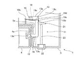
以下、この発明の実施の形態1に係るばね保持構造を、図面を参照しながら説明する。この実施の形態1は、この発明に係るばね保持構造を、車両の天井面に設置される車載情報機器に適用したものである。図1は車載情報機器の斜視図、図2は、そのII−II線に沿う断面図であり、図3はばね保持構造部分の斜視図である。
Hereinafter, a spring holding structure according to
図1は、車載情報機器1を車室内のルーフ2に取り付けた状態を示す。車載情報機器1は、車載情報機器本体3と、車載情報機器本体3に対し開閉可能に組み付けられたスクリーン部(ディスプレイ)4とからなる。車載情報機器本体3は、基板(図示せず)とロック解除ボタン22で押し動かされるレバー13などの機器が収納された機器収納部5と凹状となったスクリーン収納部6とからなり、スクリーン収納部6にスクリーン部4が収められる。スクリーン部4は、ヒンジ機構7により車載情報機器本体3に対し回動可能に支持されている。ヒンジ機構7は、スクリーン部4の基端部側の軸8と、それを回動可能に支持する、車載情報機器本体3側に固定されたブラケット9とからなる。従って、スクリーン部4は、軸8を中心に回転可能であり、車載情報機器本体3に対し回動させて開くことにより、使用できる状態、つまり使用者がスクリーン部4の画面を見ることができる状態となる。車載情報機器本体3には、スクリーン部4を所定の角度で位置決め保持する機構が備わっている。なお、車載情報機器1としては、例えばTVユニットなどがあげられる。
FIG. 1 shows a state in which an in-
車載情報機器1におけるスクリーン部4は、使用しないときには図1に示すようにスクリーン収納部6に収められるのであるが、その状態で保持するために、図2、3に示すロック装置11が設けられている。ロック装置11の構成要素としてスクリーン部4の回動端側の端面4aには係合穴12が設けられている。一方、車載情報機器本体3の内部には、ロック装置11の構成要素としてレバー13が回動可能に支持されている。レバー13は、基端部13aと、基端部13aに対し直角をなす連結部13bと、連結部13bに対し直角をなすフック部13cとからなる。フック部13cは、その車載情報機器1外側の面が斜面13dとなっている。レバー13の基端部13aにはその両側に突出するレバー軸14が設けられており、レバー軸14の両端部は、車載情報機器本体3側に設けられたレバー軸受15a、15bにより支持され、レバー13は回動可能となっている。
The screen unit 4 in the in-
車載情報機器本体3の機器収納部5のスクリーン収納部6側の壁部5aにおける、スクリーン部4の係合穴12に対応する箇所に開口16が設けられており、この開口16より、レバー13のフック部13cがスクリーン部4の係合穴12に向けて突出可能となっている。
An
一方のレバー軸受15aの側方において、車載情報機器本体3にはばね保持軸受け部17が設けられ、このばね保持軸受け部17に、前記レバー軸14と同軸をなすばね保持軸18が設けられている。このばね保持軸18にねじりコイルばね19の巻部(コイル部)19aが装着される。ねじりコイルばね19の一方の腕部19bはストレートになっており、車載情報機器本体3に形成されたばね受け部20に当接される。ねじりコイルばね19の他方の腕部19cは、ストレート部19dとストレート部19dに対しほぼ直角に曲げられた係合部19eとからなり、この係合部19eがレバー13の連結部13bの背面に当接される。よって、レバー13には、フック部13cを係合穴12に挿入させる方向に回転させるばね力が付与される。フック部13cが係合穴12に差し込まれることによりスクリーン部4は、閉状態、つまりスクリーン収納部6に収納された状態で保持される。
On the side of the one lever bearing 15a, the in-vehicle information device body 3 is provided with a spring
レバー13の連結部13bの背面には一体に受け部21が設けられている。一方、車載情報機器本体3の機器収納部5には、その外面に突出させてロック解除ボタン22が設けられている。ロック解除ボタン22には作動軸23が一体となっており、その先端は、受け部21に当接する。ロック解除ボタン22を押すことにより、その作動軸23の先端によりレバー13の受け部21が押されてレバー13がレバー軸14を中心に回動し、レバー13のフック部13cが係合穴12から外れ、スクリーン部4が回動可能な状態となる。なお、レバー13を回動させる機構として、レバー13側の受け部21、ロック解除ボタン22及び作動軸23からなる構成は一例であり、ロック解除ボタン22の直線運動をレバー13の回転運動に変換できるものであれば、どのような構造のものでも採用できる。
A receiving
スクリーン部4を開いた状態から収納する場合には、スクリーン部4を回動し、車載情報機器本体3のスクリーン部収納部6に収納して行くと、スクリーン部4が、スクリーン部4の角とフック部13cの斜面13dとの当接を介して、レバー13のフック部13cをねじりコイルばね19のばね力に抗して押し戻し、スクリーン部4がスクリーン収納部6に収納されると、係合穴12にレバー13のフック部13cが入り込み、フック部13cが係合穴12に係合し、スクリーン部4は回転しないように保持される。
When the screen unit 4 is stored from the opened state, the screen unit 4 is rotated and stored in the screen
この実施の形態1に係るばね保持構造によれば、ねじりコイルばね19が、レバー13の回転中心軸であるレバー軸14とは別に設けられたばね保持軸18に取り付けられているので、レバー軸14にはねじりコイルばね19のばね力の反力が作用することはなく、組立時にレバー軸14に変形を来たすことがなく、回転中心を維持することができ、組み付け後の寸法精度を維持することができる。しかも、レバー軸14にはねじりコイルばね19のばね力の反力が作用していないので、レバー軸14が経年変形することもない。更に、ねじりコイルばね19を支持しているばね保持軸18が、レバー13の回転軸であるレバー軸14の回転中心と一致するように配置し、ねじりコイルばね19の回転力が働く方向とレバー13の回転方向が一致するようにしてあるので、レバー13には、常に回転方向の力のみが加えられることになり、レバー13のスムーズな回転が確保できる。
According to the spring holding structure according to the first embodiment, the
実施の形態2.
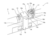
図4は、実施の形態2に係るばね保持構造を適用した車載情報機器のロック装置31の斜視図である。
レバー軸14を支持するレバー軸受15a、15bのそれぞれ側方において車載情報機器本体3にはばね保持軸受け部32a、32bが設けられ、これらのばね保持軸受け部32a、32bに、前記レバー軸14と同軸をなすばね保持軸33a、33bが設けられている。これらのばね保持軸33a、33bにねじりコイルばね34、35の巻部(コイル部)34a、35aが装着される。ねじりコイルばね34、35の一方の腕部34b、35bはストレートになっており、車載情報機器本体3に形成されたばね受け部20a、20bに当接される。ねじりコイルばね34、35の他方の腕部34c、35cは、ストレート部34d、35dとストレート部34d、35dに対しほぼ直角に曲げられた係合部34e、35eとからなり、この係合部34e、35eがレバー13の連結部13bの背面に当接される。このように、実施の形態2では、レバー13に対し、ばね保持軸33a、33b、ねじりコイルばね34、35が左右対称に配置される。レバー13には、2つのねじりコイルばね33、34により、フック部13cを係合穴12に挿入させる方向に回転させるばね力が付与される。このばね保持構造のその他の構成は、図2、3に基づいて説明した実施の形態1に係るばね保持構造と同じである。
Embodiment 2. FIG.
FIG. 4 is a perspective view of the
On the side of each of the
この実施の形態2に係るばね保持構造によれば、実施の形態1と同様の作用効果を奏するだけでなく、レバー13の両側からねじりコイルばね34、35の腕部34c、35cが当接するので、レバー13には左右両側から均等に力が作用し、レバー13にねじれ力が作用することがなく、レバーの更なるスムーズな回転が確保できる。
According to the spring holding structure according to the second embodiment, not only the effects similar to those of the first embodiment are exhibited, but also the
1 車載情報機器、3 車載情報機器本体、4 スクリーン部、11 ロック装置、12 係合穴、13 レバー、13c フック部、14 レバー軸、15a,15b レバー軸受、16 開口、18 ばね保持軸、19 ねじりコイルばね、19a 巻部、19b 腕部、19c 腕部、22 ロック解除ボタン、23 作動軸、33a,33b ばね保持軸、34,35 ねじりコイルばね。
DESCRIPTION OF
Claims (2)
Priority Applications (1)
| Application Number | Priority Date | Filing Date | Title |
|---|---|---|---|
| JP2008226012A JP5025602B2 (en) | 2008-09-03 | 2008-09-03 | Spring holding structure |
Applications Claiming Priority (1)
| Application Number | Priority Date | Filing Date | Title |
|---|---|---|---|
| JP2008226012A JP5025602B2 (en) | 2008-09-03 | 2008-09-03 | Spring holding structure |
Publications (2)
| Publication Number | Publication Date |
|---|---|
| JP2010062827A true JP2010062827A (en) | 2010-03-18 |
| JP5025602B2 JP5025602B2 (en) | 2012-09-12 |
Family
ID=42189149
Family Applications (1)
| Application Number | Title | Priority Date | Filing Date |
|---|---|---|---|
| JP2008226012A Expired - Fee Related JP5025602B2 (en) | 2008-09-03 | 2008-09-03 | Spring holding structure |
Country Status (1)
| Country | Link |
|---|---|
| JP (1) | JP5025602B2 (en) |
Citations (4)
| Publication number | Priority date | Publication date | Assignee | Title |
|---|---|---|---|---|
| JPH0774478A (en) * | 1993-09-03 | 1995-03-17 | Matsushita Electric Ind Co Ltd | Latch device |
| JPH0878089A (en) * | 1994-09-06 | 1996-03-22 | Yazaki Corp | Operation lever installation method for connector and operation lever installation mechanism |
| JP2002070400A (en) * | 2000-08-29 | 2002-03-08 | Seiko Epson Corp | Electronic equipment and grease damper |
| JP2006515710A (en) * | 2003-01-27 | 2006-06-01 | ドルミナ ユーケー リミテッド | Safety cover for electrical sockets and improvements |
-
2008
- 2008-09-03 JP JP2008226012A patent/JP5025602B2/en not_active Expired - Fee Related
Patent Citations (4)
| Publication number | Priority date | Publication date | Assignee | Title |
|---|---|---|---|---|
| JPH0774478A (en) * | 1993-09-03 | 1995-03-17 | Matsushita Electric Ind Co Ltd | Latch device |
| JPH0878089A (en) * | 1994-09-06 | 1996-03-22 | Yazaki Corp | Operation lever installation method for connector and operation lever installation mechanism |
| JP2002070400A (en) * | 2000-08-29 | 2002-03-08 | Seiko Epson Corp | Electronic equipment and grease damper |
| JP2006515710A (en) * | 2003-01-27 | 2006-06-01 | ドルミナ ユーケー リミテッド | Safety cover for electrical sockets and improvements |
Also Published As
| Publication number | Publication date |
|---|---|
| JP5025602B2 (en) | 2012-09-12 |
Similar Documents
| Publication | Publication Date | Title |
|---|---|---|
| JP4136367B2 (en) | Display device whose display unit is supported by the case body so that the posture can be controlled | |
| JP4985276B2 (en) | Outside mirror device for vehicle | |
| US7399033B2 (en) | Vehicle video display device on armrest | |
| WO2010026684A1 (en) | Biaxial hinge mechanism | |
| JP2002274261A (en) | Mirror device for vehicle | |
| JPWO2011016093A1 (en) | In-vehicle display device | |
| JP2010052723A (en) | Vehicle sun-visor | |
| JP2006218884A (en) | Sun visor for vehicle | |
| JP2006282100A (en) | Hinge mechanism of on-vehicle display | |
| JP5727671B2 (en) | Locking device | |
| JP5025602B2 (en) | Spring holding structure | |
| JPWO2016203526A1 (en) | Video display device | |
| JP4459870B2 (en) | Rotating body opening / closing angle detection device | |
| JP2008048784A (en) | Armrest device of vehicle | |
| JP4999445B2 (en) | Console hinge structure | |
| JP2007326480A (en) | Indoor ceiling arrangement device | |
| JP3178909U (en) | Seat back unlock lever | |
| JP2013237373A (en) | Door mirror for vehicle | |
| JP4179408B2 (en) | HINGE DEVICE AND ELECTRONIC DEVICE USING HINGE DEVICE | |
| JP2006070604A (en) | Rotary lock | |
| JP4323999B2 (en) | Automotive sun visor | |
| WO2010001510A1 (en) | Display device | |
| JP2011026794A (en) | Handle device | |
| JP5950846B2 (en) | Remote control storage structure and electronic device including the same | |
| JP5704748B2 (en) | Auxiliary bracket fixing structure with connector |
Legal Events
| Date | Code | Title | Description |
|---|---|---|---|
| A621 | Written request for application examination |
Free format text: JAPANESE INTERMEDIATE CODE: A621 Effective date: 20101007 |
|
| A977 | Report on retrieval |
Free format text: JAPANESE INTERMEDIATE CODE: A971007 Effective date: 20120514 |
|
| TRDD | Decision of grant or rejection written | ||
| A01 | Written decision to grant a patent or to grant a registration (utility model) |
Free format text: JAPANESE INTERMEDIATE CODE: A01 Effective date: 20120522 |
|
| A01 | Written decision to grant a patent or to grant a registration (utility model) |
Free format text: JAPANESE INTERMEDIATE CODE: A01 |
|
| A61 | First payment of annual fees (during grant procedure) |
Free format text: JAPANESE INTERMEDIATE CODE: A61 Effective date: 20120619 |
|
| FPAY | Renewal fee payment (event date is renewal date of database) |
Free format text: PAYMENT UNTIL: 20150629 Year of fee payment: 3 |
|
| R150 | Certificate of patent or registration of utility model |
Ref document number: 5025602 Country of ref document: JP Free format text: JAPANESE INTERMEDIATE CODE: R150 Free format text: JAPANESE INTERMEDIATE CODE: R150 |
|
| R250 | Receipt of annual fees |
Free format text: JAPANESE INTERMEDIATE CODE: R250 |
|
| R250 | Receipt of annual fees |
Free format text: JAPANESE INTERMEDIATE CODE: R250 |
|
| R250 | Receipt of annual fees |
Free format text: JAPANESE INTERMEDIATE CODE: R250 |
|
| R250 | Receipt of annual fees |
Free format text: JAPANESE INTERMEDIATE CODE: R250 |
|
| R250 | Receipt of annual fees |
Free format text: JAPANESE INTERMEDIATE CODE: R250 |
|
| R250 | Receipt of annual fees |
Free format text: JAPANESE INTERMEDIATE CODE: R250 |
|
| LAPS | Cancellation because of no payment of annual fees |