JP2010062600A - Method of managing radio communication system, program and device for executing the same, and system including the same - Google Patents
Method of managing radio communication system, program and device for executing the same, and system including the same Download PDFInfo
- Publication number
- JP2010062600A JP2010062600A JP2008223037A JP2008223037A JP2010062600A JP 2010062600 A JP2010062600 A JP 2010062600A JP 2008223037 A JP2008223037 A JP 2008223037A JP 2008223037 A JP2008223037 A JP 2008223037A JP 2010062600 A JP2010062600 A JP 2010062600A
- Authority
- JP
- Japan
- Prior art keywords
- radio base
- communication
- base station
- relay device
- relay
- Prior art date
- Legal status (The legal status is an assumption and is not a legal conclusion. Google has not performed a legal analysis and makes no representation as to the accuracy of the status listed.)
- Granted
Links
Images


Abstract
Description
本発明は、無線通信端末と無線通信する複数の無線基地局と、少なくとも1つの無線基地局を収容する中継装置と、を備えている無線通信システムの管理技術に関し、特に、中継装置の台数変更時の管理技術に関する。 The present invention relates to a management technique for a wireless communication system including a plurality of wireless base stations that wirelessly communicate with a wireless communication terminal and a relay device that accommodates at least one wireless base station, and in particular, to change the number of relay devices. Time management technology.
近年、移動体通信サービスの発展に伴い、この移動体通信サービスを利用するユーザが増加している。移動体通信事業者は、移動体通信ユーザの増加に伴い、移動体通信システムのカバーエリア拡大および移動体通信ユーザ収容能力を増強させる必要がある。 In recent years, with the development of mobile communication services, the number of users who use this mobile communication service is increasing. With the increase in mobile communication users, mobile communication operators need to expand the coverage area of mobile communication systems and increase the capacity of mobile communication users.
このカバーエリア拡大および移動体通信ユーザ収容能力の増強には、基地局の増設と、この基地局を収容する中継装置の増設が必要である。中継装置は、単に、増設されてだけでは、基地局が収容されていないため、中継装置として機能しない。このため、移動体通信事業者は、中継装置を増設した後、まず、既設の中継装置に収容されている基地局のうち、いずれの基地局を新に増設した中継装置に収容させるかを定める、すなわち、収容設計を行う。そして、この収容設計結果に基づいて、新に増設した中継装置に対して、既設の中継装置に収容されている幾つかの基地局の収容変更の設定作業を行い、さらに、この収容変更に伴い、既設の中継装置に対しても基地局の収容変更の設定作業を行う。 In order to expand the cover area and increase the mobile communication user capacity, it is necessary to add a base station and a relay device that accommodates the base station. The relay device simply does not function as a relay device because the base station is not accommodated only by being added. For this reason, after adding a relay device, the mobile communication carrier first determines which of the base stations accommodated in the existing relay device is accommodated in the newly added relay device. That is, the accommodation design is performed. And based on this accommodation design result, setting work for the accommodation change of several base stations accommodated in the existing relay device is performed for the newly added relay device, and further, along with this accommodation change The base station accommodation change setting operation is also performed for the existing relay apparatus.
以上のように、中継装置の増設では、収容設計作業及び収容変更の設定作業が必要であり、この作業工数は多大である。このため、これらの作業の効率化が望まれているのが現状である。 As described above, expansion of the relay device requires accommodation design work and accommodation change setting work, and this work man-hour is enormous. For this reason, the present situation is that the efficiency of these operations is desired.
そこで、以下の特許文献1では、各中継装置等へ収容変更コマンドを入力することで、収容変更の設定が行われるようにして、収容変更の設定作業の効率化を図る技術が開示されている。
Therefore,
上記特許文献1に記載の技術は、中継装置の増設に伴う作業の効率化を図ることができるものの、移動体通信事業者は更なる効率化を望んでいる。
Although the technology described in
そこで、本発明では、中継装置の台数変更に伴う作業をより効率化することを目的とする。 Therefore, an object of the present invention is to make the work associated with changing the number of relay devices more efficient.
前記目的を達成するため、本発明では、
コンピュータの通信手段により、複数の無線基地局から又は1以上の中継装置から該複数の無線基地局のそれぞれの通信負荷を取得して、コンピュータの記憶手段に格納する。さらに、予め定められた条件を満たす毎に、前記通信手段により、問合せ可能な全ての中継装置に対して、呼制御可能な稼動中であるかの状態問合せを行い、該状態問合わせの返答により、該全ての中継装置の状態を把握し、該全ての中継装置のうち稼動中の中継装置の識別子のみを、又は、非稼動の中継装置の識別子に対して稼働中の中継装置の識別子を区別できるよう、前記コンピュータの記憶手段に記憶する。
In order to achieve the above object, in the present invention,
The communication load of each of the plurality of radio base stations is obtained from the plurality of radio base stations or from one or more relay devices by the computer communication means, and stored in the storage means of the computer. Further, every time a predetermined condition is satisfied, the communication means inquires about all the relay devices that can be inquired about whether or not the call control is in operation, and returns the state inquiry response. , Grasp the status of all the relay devices, and distinguish only the identifier of the active relay device among all the relay devices, or distinguish the identifier of the active relay device from the identifier of the non-operating relay device Store in the storage means of the computer so that it can.
この記憶手段に記憶されている前記稼動中の中継装置の識別子の数が変化すると、該稼動中の各中継装置毎の全収容無線基地局の通信負荷に応じた該中継装置の通信負荷が、各中継装置相互間で均等に近づくよう、該稼動中の各中継装置の識別子に対して、収容する無線基地局の識別子を割り付け、割付結果をコンピュータの記憶手段に格納する。そして、稼動中である各中継装置に対して、収容する無線基地局が割り付けられると、前記記憶手段に格納されている前記割付結果を参照して、該各中継装置に対して収容する一以上の無線基地局の識別子を通知すると共に、各無線基地局に対して収容される中継装置の識別子を通知する。 When the number of identifiers of the active relay device stored in the storage means changes, the communication load of the relay device according to the communication load of all accommodated radio base stations for each active relay device, The identifiers of the radio base stations to be accommodated are allocated to the identifiers of the relay devices in operation so that the relay devices are equally approached, and the allocation result is stored in the storage means of the computer. Then, when a radio base station to be accommodated is allocated to each active relay device, one or more to be accommodated to each relay device with reference to the allocation result stored in the storage means And the identifier of the relay apparatus accommodated in each radio base station.
本発明によれば、収容設計作業及び収容変更の設定作業の自動化が図られるため、中継装置の増設に伴う作業の効率化を図ることができる。 According to the present invention, since the accommodation design work and the accommodation change setting work are automated, the work efficiency associated with the addition of the relay device can be improved.
以下、本発明に係る無線通信システムの一実施形態について、図面を用いて説明する。 Hereinafter, an embodiment of a wireless communication system according to the present invention will be described with reference to the drawings.
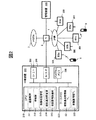
本実施形態の無線通信システムは、図1に示すように、例えば、携帯電話等の無線通信端末5と無線通信する複数の無線基地局300,300,…と、無線基地局300に帰属した無線通信端末5の呼制御を行う複数の中継装置200,200,…と、これらを管理する管理装置100と、を備えている。
As shown in FIG. 1, the wireless communication system according to the present embodiment includes, for example, a plurality of
複数の無線基地局300,300,…と複数の中継装置200,200,…と管理装置100とは、ルータ2を介して、互いに通信可能にIP(Internet Protocol)網1により接続されている。このIP網1には、ルータ2を介して、公衆網3も接続されている。
The plurality of
管理装置100は、各種演算処理を実行するCPU110と、このCPU110のワークエリアとなるメモリ120と、各種データが格納されているハードディスクドライブ装置等の記憶装置130と、IP網1を介して他の装置200,300等と通信するためのネットワークインタフェース140と、入出力インタフェース150と、キーボード等の入力装置151と、表示装置152と、を備えている。
The
CPU110は、機能的に、他の装置との通信制御を行う通信制御部111と、各中継装置200や各基地局300がそれぞれの機能を発揮できる稼動状態であるか否かを把握する稼動状態把握部112と、各基地局300の通信負荷を各基地局300から取得する通信負荷取得部113と、いずれの中継装置200にいずれの基地局300を収容させるかの収容設計を行う収容設計部114と、収容設計部114による収容設計の結果を各中継装置200や各基地局300に通知する収容変更指示部115と、を有している。
The
記憶装置130には、当該無線通信システムを構成する各中継装置200や各基地局300の情報が格納されているシステム構成情報テーブル131と、通信負荷取得部113で取得された各基地局300の通信負荷が格納される通信負荷情報テーブル132と、が設けられている。さらに、この記憶装置130には、他の装置との通信を行うための通信プログラム133と、当該無線通信システムを管理するためのシステム管理プログラム134と、自装置100の通信アドレス等が予め格納されている。なお、前述の通信制御部111は、CPU110がこの記憶装置130に格納されている通信プログラム133を実行することで機能する。また、前述の稼動状態把握部112、通信負荷取得部113、収容設計部114、収容変更指示部115は、いずれも、CPU110がシステム管理プログラム134を実行することで機能する。
In the
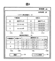
記憶装置130に設けられているシステム構成情報テーブル131は、図4に示すように、当該管理装置100の管理下にある中継装置200の識別子が格納されるID領域131aと、該当中継装置200の通信アドレスが格納される通信アドレス領域131bと、該当中継装置200に収容されている基地局300の識別子が格納されるID領域131cと、該当基地局300の通信アドレスが格納される通信アドレス領域131dと、を有している。
As shown in FIG. 4, the system configuration information table 131 provided in the
また、記憶装置130に設けられている通信負荷情報テーブル132は、当該管理装置100の管理下にある中継装置200の識別子が格納されるID領域132aと、該当中継装置200に収容されている基地局300の識別子が格納されるID領域132bと、該当基地局300での各時点での通信負荷が格納される通信負荷領域132cと、該当基地局30での過去の通信負荷の平均値が格納される平均通信負荷領域132dと、を有している。なお、基地局300の通信負荷とは、ここでは、当該基地局300に帰属している無線通信端末5の台数のことである。
Further, the communication load information table 132 provided in the
中継装置200は、図2に示すように、各種演算処理を実行するCPU210と、このCPU210のワークエリア等になるワークメモリ220と、各種データやプログラムが格納されているプログラムメモリ230と、IP網1を介して他の装置100,300等と通信するためのネットワークインタフェース240と、キーボード等の入力装置等が接続される入出力インタフェース250と、を備えている。
As shown in FIG. 2, the
CPU210は、機能的に、他の装置との通信制御を行う通信制御部211と、収容している基地局300に帰属中の無線通信端末5の呼制御(回線制御)を行う呼制御部212と、自装置200が呼制御可能な稼動状態であるか否かを管理する稼動状態管理部213と、ワークメモリ220に格納されている収容基地局300のID等を変更する収容基地局変更部214と、自装置200の情報を管理装置100へ通知する自装置情報通知部215と、を有している。なお、以上の各機能部211〜215は、いずれも、CPU210がプログラムメモリ230に格納されているプログラムを実行することで機能する。
The
ワークメモリ220には、自装置200が収容している基地局300の情報が格納される収容基地局情報テーブル221と、自装置200の情報が格納されている自装置情報テーブル222と、が設けられている。
The
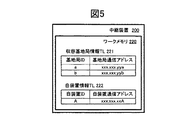
ワークメモリ220に設けられている収容基地局情報テーブル221は、図5に示すように、自装置200が収容している基地局300の識別子が格納されるID領域と、該当基地局300の通信アドレスが格納される通信アドレス領域と、を有している。
As shown in FIG. 5, the accommodated base station information table 221 provided in the
また、ワークメモリ220に設けられている自装置情報テーブル222は、自装置200の識別子が格納されているID領域と、自装置200の通信アドレスが格納されている通信アドレス領域と、を有している。この自装置情報テーブル222のデータは、この中継装置200が設置された段階又はそれ以前に格納される。
The own device information table 222 provided in the
基地局300は、図3に示すように、各種演算処理を実行するCPU310と、このCPU310のワークエリア等になるワークメモリ320と、各種データやプログラムが格納されているプログラムメモリ330と、IP網1を介して他の装置100,200等と通信するためのネットワークインタフェース340と、無線通信端末5との間で無線通信するためのアンテナ351と、このアンテナ351が接続されている無線インタフェース350と、無線インタフェース350とネットワークインタフェース340との間の信号変換処理を行う変換部360と、を備えている。
As shown in FIG. 3, the
CPU310は、機能的に、他の装置との通信制御を行う通信制御部311と、自装置300の通信負荷を監視する通信負荷監視部312と、自装置300が無線通信端末5と中継装置200との間の中継処理が可能な稼動状態であるか否かを管理する稼動状態管理部313と、ワークメモリ320に格納されている収容先中継装置200のID等を変更する収容先中継装置変更部314と、を有している。なお、以上の各機能部311〜314は、いずれも、CPU310がプログラムメモリ330に格納されているプログラムを実行することで機能する。
The
ワークメモリ320には、帰属した又は帰属処理中の無線通信端末5の情報が格納される接続端末情報テーブル321と、自装置300の通信負荷が格納される通信負荷記憶部322と、収容先の中継装置200の情報が格納される中継装置情報テーブル323と、が設けられている。さらに、このワークメモリ320には、自装置300の通信アドレスや識別子等が予め格納されている。
The
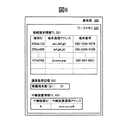
ワークメモリ320に設けられている接続端末情報テーブル321は、図6に示すように、帰属した又は帰属処理中の無線通信端末5の識別子が格納されるID領域と、この端末の通信アドレスが格納される通信アドレス領域と、この端末の電話番号が格納される端末番号領域と、を有している。なお、ここでは、省略しているが、このテーブル321には、さらに、接続先端末の電話番号等の領域がある。
As shown in FIG. 6, the connection terminal information table 321 provided in the
また、ワークメモリ320に設けられている通信負荷記憶部322には、接続端末情報テーブル321のレコード数、つまりこのテーブル321に格納されている端末ID数、が通信負荷として格納される。また、ワークメモリ320に設けられている中継装置情報テーブル323は、収容先の中継装置200の識別子が格納されるID領域と、この中継装置200の通信アドレスが格納される通信アドレス領域と、を有している。
Further, the communication load storage unit 322 provided in the
次に、図8に示すシーケンス図に従って、本実施形態における無線通信システムの動作について説明する。なお、ここでは、図1に示すように、基地局a〜e、中継装置A,Bが既に稼動している状態で、ここに新に中継装置Cを増設する場合について説明する。 Next, the operation of the wireless communication system in the present embodiment will be described according to the sequence diagram shown in FIG. Here, as shown in FIG. 1, a case will be described in which a base station a to e and relay apparatuses A and B are already in operation and a relay apparatus C is newly added here.
管理装置100の通信負荷取得部113は、図1及び図7に示すように、通信制御部111を介して、全ての基地局a〜eに対して、後述するように、定期的に、通信負荷の通知を要求する(S101)。このとき、通信制御部111は、図4及び図7に示すシステム構成情報テーブル131から各基地局a〜eの通信アドレスを取得し、通信負荷の通知要求を各基地局a〜eへ送信する。なお、図7では、システム構成情報テーブル131の構成を簡略化していると共に、中継装置や収容基地局の通信アドレスも簡略化している。さらに、図7では、通信負荷情報テーブル132の構成も簡略化している。
As shown in FIGS. 1 and 7, the communication
各基地局a〜eの通信負荷監視部312は、通信制御部311を介して、管理装置100からの通信負荷の通知要求を受け取ると、通信負荷記憶部322(図6)に記憶されている帰属端末数を通信負荷として、管理装置100へ送信する(S301)。各基地局a〜eの呼制御部312は、無線通信端末5と他の端末との通信接続処理の過程で、この無線通信端末5の情報を接続端末情報テーブル321に格納し、この無線通信端末5と他の端末との通信が終了すると、先に格納した情報を削除する。通信負荷監視部312は、この接続端末情報テーブル321を監視し、この接続情報テーブル321のレコード数、つまり帰属した又は帰属処理中の無線通信端末5の数を通信負荷記憶部322に格納する。この通信負荷監視部312は、管理装置100からの要求に応じて、前述したように、この通信負荷記憶部322に格納されている無線通信端末5の数を通信負荷として、管理装置100へ送信する。
When the communication
ここで、中継装置Cが設置されたとする。この中継装置Cの電源がONになり(S201)、この中継装置Cが通信可能になり、呼制御が可能な稼動状態になると、自装置情報通知部215が、この中継装置Cの設置時又はそれ以前にワークメモリ220に格納された自装置情報テーブル222を参照して、自装置CのID及び通信アドレスを、通信制御部211を介して管理装置100へ通知する(S202)。
Here, it is assumed that the relay apparatus C is installed. When the power of the relay device C is turned on (S201), the relay device C becomes communicable and is in an operation state in which call control is possible, the own device
管理装置100の収容設計部114は、通信制御部111を介して、この通知を受け取ると、図7に示すように、システム構成情報テーブル131に新たなレコードを追加して、このレコード中に、新に設置された中継装置CのID及び通信アドレスを格納する。なお、本実施形態では、新に設置された中継装置Cの情報として、この中継装置Cから送られてきたものをシステム構成情報テーブル131に格納しているが、この替わりに、入力装置151(図1)から入力された中継装置CのID等をシステム構成情報テーブル131に格納するようにしてもよい。
Upon receipt of this notification via the
管理装置100の稼動状態把握部112は、図1及び図7に示すように、通信制御部111を介して、システム構成情報テーブル131に通信アドレスが格納されている全ての中継装置A〜C及び基地局a〜eに対して、後述するように、定期的に、状態情報の通知を要求する(S102)。
As shown in FIGS. 1 and 7, the operation
全ての中継装置A〜C及び基地局a〜eの稼動状態管理部213,313は、通信制御部211,311を介して、この通知を受け取ると、自装置が稼動状態であるか否かを、通信制御部211,311を介して管理装置100へ通知する(S204,S304)。中継装置及び基地局の稼動状態管理部213,313は、自装置が自装置に求められている機能を実行可能な稼動状態であるか否かを常に把握しており、この把握している状態を管理装置100に通知する。
When the operation
管理装置100の稼動状態把握部112は、図1及び図7に示すように、通信制御部111を介して、全ての中継装置A〜C及び基地局a〜eから状態情報通知を受け取ると、この通知に基づき、通信負荷情報テーブル132を更新する。この場合、稼動状態把握部111は、新に中継装置Cから稼動状態である旨の状態情報通知を受けているので、通信負荷情報テーブル132に新たなレコードを設けて、このレコードに、この中継装置CのID「C」を格納する。続いて、稼動状態把握部112は、通信負荷情報テーブル132中のレコード数、言い換えると、中継装置の稼動台数に変化があったか否かを判断する(S104)。稼動状態把握部112は、中継装置の稼動台数に変化があったと判断すると、収容設計部114に対して、収容設計の実行を指示する。
As shown in FIGS. 1 and 7, the operation
収容設計部114は、この指示を受けて起動すると、後述するように、収容設計を実行し(S105)、この収容設計結果に基づいて、システム構成情報テーブル131及び通信負荷情報テーブル132を変更する(S106)。具体的には、各テーブル131,132中の、中継装置とこの中継装置に収容される基地局との関係を変更する。そして、収容設計部114は、収容変更指示部115に対して、収容変更指示の実行を指示する。
When the
収容変更指示部115は、この指示を受けて起動すると、後述するように、変更されたシステム構成情報テーブル131を参照して、各中継装置A〜Cに対しては、収容する基地局のID及び通信アドレスを含む変更指示を送信し、各基地局a〜eに対しては、収容先の中継装置のID及び通信アドレスを含む変更指示を送信する(S107)。
When the accommodation
各中継装置A〜Cの収容基地局変更部214は、通信制御部211を介して、この変更指示を受け取ると、この変更指示に含まれている収容基地局のID等に従って、収容基地局情報テーブル221を変更する(S208)。なお、新に設置された中継装置Cの収容基地局変更部214は、収容基地局のID等を収容基地局情報テーブル221に新規登録する(S208a)。収容基地局変更部214は、収容基地局情報テーブル221を変更すると、通信制御部211を介して、管理装置100へ変更完了通知を送信する(S209)。
When the accommodation base
また、各基地局a〜eの収容先中継装置変更部314は、通信制御部311を介して、この変更指示を受け取ると、この変更指示に含まれている収容先の中継装置のID等に従って、中継装置情報テーブル323を変更する(S308)。収容先中継装置変更部314は、中継装置情報テーブル232を変更すると、管理装置100へ変更完了通知を送信する(S309)。
Further, when the accommodation destination relay
以上のように、本実施形態では、中継装置200の台数変更に伴う収容設計及び収容変更指示を管理装置100が実行するので、この台数変更に伴う作業の効率化を図ることができる。
As described above, in this embodiment, since the
次に、図9に示すフローチャートに従って、管理装置100による、各基地局300の通信負荷の取得処理について説明する。
Next, the communication load acquisition process of each
管理装置100の通信負荷取得部113は、通信負荷の収集タイミングになると(S110)、システム構成情報テーブル131に記憶されている全ての基地局300に対し、通信制御部111を介して、通信負荷の通知要求を送信する(S111、(図8中のS101))。通信負荷の収集タイミングは、予め定められた間隔(例えば、1時間)毎に設定されており、通信負荷取得部113は、この間隔を経過したか否かにより収集タイミングになったか否かを判断する。
When the communication
この通信負荷の通知要求に対して、各基地局300は、図8を用いて前述したように、自装置の通信負荷の通知を管理装置100に返す。管理装置100の通信負荷取得部113は、通信制御部111を介して、この通信負荷の通知を受け取ると(S112)、この通知に基づいて、通信負荷情報テーブル132を更新し(S113)、通信負荷の取得理を終了する。
In response to this communication load notification request, each
通信負荷取得部113は、各基地局300からの通信負荷通知を受け取ると、この通知に含まれている通信負荷(基地局の帰属数)を、通信負荷情報テーブル132の該当基地局のレコード中の最新の通信負荷領域132cに格納する。さらに、通信負荷取得部113は、過去から現時点までの通信負荷の平均値を求め、これを平均通信負荷領域132dに格納する。
Upon receiving the communication load notification from each
なお、本実施形態では、各基地局300の通信負荷の通知を各基地局に要求しているが、各中継装置200は、収容基地局300の通信負荷を把握し得るので、このよう場合には、各中継装置200に対して、各基地局300の通信負荷の通知を要求してもよい。
In this embodiment, each
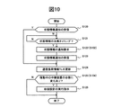
次に、図10に示すフローチャートに従って、管理装置100による、各中継装置200及び各基地局300の稼動状態の把握処理について説明する。
Next, according to the flowchart shown in FIG. 10, the operation status grasping process of each
管理装置100の稼動状態把握部112は、常に、通信制御部111が外部から状態情報通知を受信したか否かを監視している(S120)。通信制御部111が外部から状態情報通知を受信した場合には、稼動状態把握部112は、ステップ124に進み、この状態情報通知に従って、通信負荷情報テーブル132を更新する。
The operation
また、通信制御部111が外部から状態情報通知を受信していない場合、稼動状態把握部112は、状態情報の収集タイミングになるまで待ち(S121)、収集タイミングになると、システム構成情報テーブル131に記憶されている全ての中継装置200及び全ての基地局300に対し、通信制御部111を介して、状態情報の通知要求を送信する(S122、(図8中のS102))。通信負荷の収集タイミングは、予め定められた間隔(例えば、1日)毎に設定されており、稼動状態把握部112は、この間隔を経過したか否かにより収集タイミングになったか否かを判断する。
Further, when the
この通信負荷の通知要求に対して、各中継装置200及び各基地局300は、図8を用いて前述したように、自装置の稼動状態の通知を管理装置100に返す。管理装置100の稼動状態把握部112は、通信制御部111を介して、この稼動状態の通知を受け取ると(S123)、この通知に基づいて、通信負荷情報テーブル132を更新する(S124)。
In response to this communication load notification request, each
なお、本実施形態において、常に、通信制御部111が状態情報通知を受信したか否かを監視(S120)しているのは、中継装置200や基地局300の稼動停止を事前に、若しくは稼動停止直後に把握するためである。稼動状態把握部112は、前述したように、定期的に状態情報の通知要求を送信し(S122)、この要求により各装置から状態情報を受信する(S123)。仮に、この要求に対して、要求送信先から状態情報が返ってこなければ、稼動状態把握部112は、この要求送信先が稼動状態でなくなったこと、言い換えると、要求送信先の装置が撤去された又は故障したことを把握することができる。しかしながら、このような方法で装置が撤去等されたことを把握し、その後、収容設計をした場合、撤去等された装置が機能しなくなってから、新に収容設計が行われ、システムを構成する各装置200,300が設定を変更されるまでのタイムラグが大きくなってしまう。そこで、本実施形態では、常に、通信制御部111が状態情報通知を受信したか否かを監視し(S120)、中継装置200や基地局300の稼動停止を事前に若しくは稼動停止直後に把握できるようにしている。この場合の状態情報の送信元は、稼動停止する中継装置200又は基地局300であってもよいが、何らかの手段により、稼動停止を知った、このシステムの運営者の端末であってもよい。
In the present embodiment, whether or not the
稼動状態把握部112は、この稼動状態の通知に基づいて、通信負荷情報テーブル132を更新する際(S124)、この通知が新に稼動状態になった装置からの通知である場合には、通信負荷情報テーブル132にこの装置用のレコードを設けて、このレコード中にこの装置のIDを格納し、この通知が稼動停止である旨の通知である場合には、通信負荷情報テーブル132から、非稼動装置のレコードを削除する。なお、ここでは、非稼動装置のレコードを削除しているが、稼動装置と非稼動装置とが区別可能にしておけば、非稼動装置のレコードを削除する必要はない。
When the operation
稼動状態把握部112は、通信負荷情報テーブル132を更新すると、この通信負荷情報テーブル132を参照して、稼動中の中継装置200の台数に変化があったか否かを判断する(S125(図8中のS104))。稼動中の中継装置200の台数に変化がなければ、この稼動状態把握処理を終了する。また、稼働中の中継装置200の台数に変化があれば、収容設計部114に対し、収容設計の実行を指示して(S126)、この稼動状態把握処理を終了する。
When the communication load information table 132 is updated, the operating
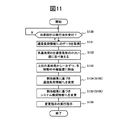
次に、図11に示すフローチャートに従って、管理装置100による収容設計処理について説明する。
Next, the accommodation design process by the
管理装置100の収容設計部114は、稼動状態把握部112から収容設計の実行を指示されると(S130)、通信負荷情報テーブル132のデータを取得し、このコピーをメモリ120上に展開する(S131)。次に、メモリ120上に展開した通信負荷情報テーブル132のデータのうち、各基地局IDを平均通信負荷の小さい順に並べ替える(S132)。具体的には、基地局aの平均通信負荷が「24」、基地局bの平均通信負荷が「14」、基地局cの平均通信負荷が「28」、基地局dの平均通信負荷が「19」、基地局eの平均通信負荷が「8」の場合、図7のメモリ120上に展開されているように、基地局IDを、e→b→d→a→cの順に並べる。
When the
次に、収容設計部114は、上位の基地局から1台ずつを、各稼動中の中継装置A〜Cに順次割り当てる(S133)。具体的には、図7のメモリ120上に展開されているように、基地局eに対して中継装置A、基地局bに対して中継装置B、基地局dに対して中継装置C、基地局aに対して中継装置A、基地局cに対して中継装置Bを割り当てる。
Next, the
次に、収容設計部114は、ステップ133での割当結果に基づき、通信負荷情報テーブル132内の中継装置200と基地局300との収容関係を変更する(S134(図8中のS106))。すなわち、図7中の変更後の通信負荷情報テーブル132のように、中継装置Aが基地局e,aを収容し、中継装置Bが基地局b,cを収容し、新に設置された中継装置Cが基地局dを収容するように、収容関係を変更する。なお、通信負荷情報テーブル132において、各基地局a〜eに対する通信負荷及び平均通信負荷は、元の関係のままである。
Next, the
次に、収容設計部114は、ステップ133での割当結果に基づき、システム構成情報テーブル131内の中継装置200と基地局300との収容関係も、通信負荷情報テーブル132と同様に、を変更する(S135(図8中のS106))。なお、ここでは、通信負荷情報テーブル132を先に変更したが、システム構成情報テーブル131を先に変更してもよいことは言うまでもない。
Next, the
収容設計部114は、各テーブル131,132を変更すると、収容変更指示部115に対して各装置200,300への変更指示の実行を指示して(S126)、この収容設計処理を終了する。
When the
なお、以上では、各基地局IDを平均通信負荷の小さい順に並べ替えてから(S132)、上位の基地局から1台ずつを各稼働中の中継装置に順次割り付けているが(S133)、基地局IDを平均通信負荷の大きい順に並べ替えてから、上位の基地局から1台ずつを各稼働中の中継装置に順次割り付けてもよい。つまり、稼働中の各中継装置の通信負荷が均等に近づくように、各中継装置に対して各基地局を割り付けることができれば、如何なる方法で各基地局を割り付けてもよい。 In the above description, the base station IDs are rearranged in order of increasing average communication load (S132), and one unit from the upper base station is sequentially assigned to each active relay device (S133). The station IDs may be rearranged in descending order of the average communication load, and then one station from the upper base station may be sequentially allocated to each active relay device. That is, each base station may be allocated by any method as long as each base station can be allocated to each relay apparatus so that the communication load of each active relay apparatus approaches equally.
また、以上では、各基地局の通信負荷として、各基地局に対する帰属端末数を用いているが、各基地局の通信負荷に対応するパラメータであれば、以下のいずれのパラメータ1)〜3)を用いてもよい。 In the above description, the number of terminals belonging to each base station is used as the communication load of each base station. However, any of the following parameters 1) to 3) is applicable as long as the parameter corresponds to the communication load of each base station. May be used.
1)基地局の単位時間当たりの実際の送信ビット数、つまり通信トラフィック量、又は単位時間当たりの最大送信ビット数に対する単位時間当たりの実際の送信ビット数の割合
2)予め定めた帰属台数に対する実際の帰属台数の割合
3)基地局の通信処理を実行するCPUの最大処理能力に対する実処理能力の割合
次に、図12に示すフローチャートに従って、管理装置100による収容変更指示処理について説明する。
1) The actual number of transmission bits per unit time of the base station, that is, the amount of communication traffic, or the ratio of the actual number of transmission bits per unit time to the maximum number of transmission bits per unit time 2) Actual to the predetermined number of belongings 3) Ratio of actual processing capacity to maximum processing capacity of CPU executing communication processing of base station Next, the accommodation change instruction processing by the
管理装置100の収容変更指示部115は、収容設計部114から収容変更指示の実行を指示されると(S140)、システム構成情報テーブル131を参照して、各装置200,300へ送信する変更指示情報を作成する(S141)。具体的には、例えば、中継装置Aへ送信する変更指示情報として、収容基地局e,aのID及び通信アドレスを含む情報を作成し、基地局Aへ送信する変更指示情報として、収容先の中継装置AのID及び通信アドレスを含む情報を作成する。
When the accommodation
収容変更指示部115は、変更指示情報を作成すると、各装置200,300毎の変更指示を各装置200,300へ送信する(S142(図8中のS107))。そして、所定時間、変更指示の全送信先からの変更完了通知の受信を待ち(S143)、いずれか送信先から変更完了通知を受信できない場合には、この送信先へ再度変更指示を送信し、全送信先から変更管理を受信すると、この収容変更指示処理を終了する。
When creating the change instruction information, the accommodation
1:IP網、2:ルータ、3:PSTN、5:無線通信端末、100:管理装置、110,210,310:CPU、111,211,311:通信制御部、112:稼動状態把握部、113:通信負荷取得部、114:収容設計部、115:収容変更指示部、120:メモリ、130:記憶装置、131:システム構成情報テーブル、132:通信負荷情報テーブル、133:通信プログラム、134:システム管理プログラム、140,240,340:ネットワークインタフェース、200:中継装置、212:呼制御部、213,313:稼動状態管理部、214:収容基地局変更部、215:自装置情報通知部、220,320:ワークメモリ、221:収容基地局情報テーブル、222:自装置情報テーブル、230,330:プログラムメモリ、312:通信負荷監視部、314:収容先中継装置変更部、321:接続端末情報テーブル、322:通信負荷記憶部、323:中継装置情報テーブル、350:無線インタフェース、360:変換部 1: IP network, 2: router, 3: PSTN, 5: wireless communication terminal, 100: management device, 110, 210, 310: CPU, 111, 211, 311: communication control unit, 112: operating state grasping unit, 113 : Communication load acquisition unit, 114: accommodation design unit, 115: accommodation change instruction unit, 120: memory, 130: storage device, 131: system configuration information table, 132: communication load information table, 133: communication program, 134: system Management program, 140, 240, 340: network interface, 200: relay device, 212: call control unit, 213, 313: operating state management unit, 214: accommodation base station change unit, 215: own device information notification unit, 220, 320: Work memory, 221: Accommodating base station information table, 222: Own device information table, 230, 330: Program memory, 312: communication load monitoring unit, 314: accommodating repeater changing unit, 321: connection terminal information table 322: communication load storage unit, 323: relay apparatus information table 350: radio interface, 360: transform unit
Claims (8)
前記複数の無線基地局のそれぞれの通信負荷を、該複数の無線基地局から又は前記1以上の中継装置から取得する通信負荷取得手段と、
問合せ可能な全ての中継装置に対して、呼制御可能な稼動中であるかの状態問合せを行って、該状態問合わせの返答により、該全ての中継装置の状態を把握する状態把握手段と、
前記状態把握手段により、前記稼動中の中継装置の台数の変化が把握されると、該稼動中の各中継装置毎の全収容無線基地局の通信負荷に応じた該中継装置の通信負荷が、各中継装置相互間で均等に近づくよう、該稼動中の各中継装置に対して、収容する無線基地局を割り付ける収容設計手段と、
前記収容設定手段により、前記稼動中の各中継装置に対して、収容する無線基地局が割り付けられると、該各中継装置に対して収容する一以上の無線基地局を通知すると共に、各無線基地局に対して収容される中継装置を通知する収容変更指示手段と、
を備えていることを特徴とする無線通信システムの管理装置。 A plurality of radio base stations that perform radio communication with the radio communication terminal; and at least one radio base station, and one or more relay apparatuses that perform call control of the radio communication terminal belonging to the radio base station. In a management device for a wireless communication system,
Communication load acquisition means for acquiring the communication load of each of the plurality of radio base stations from the plurality of radio base stations or from the one or more relay devices;
A state grasping means for making a state inquiry as to whether or not call control is possible for all relay devices that can be inquired, and grasping the state of all the relay devices by replying to the state inquiry;
When the status grasping means grasps the change in the number of the active relay devices, the communication load of the relay devices according to the communication load of all the accommodated radio base stations for each active relay device is: Accommodation design means for allocating a radio base station to be accommodated for each active relay device so as to approach each relay device equally.
When the accommodation setting unit assigns a radio base station to be accommodated to each active relay device, the radio base station notifies one or more radio base stations to be accommodated to each relay device. Accommodation change instructing means for notifying a relay device accommodated to a station;
An apparatus for managing a wireless communication system, comprising:
管理する全ての中継装置の識別子及び通信アドレスを記憶していると共に、各中継装置の識別子に対応付けて、各中継装置が収容している無線基地局の識別子及び通信アドレスを記憶しているシステム構成情報記憶手段を備え、
前記収容設計手段は、前記稼動中である各中継装置に対する無線基地局の割付結果に応じて、前記システム構成情報記憶手段に記憶されている前記各中継装置の識別子に対応付ける無線基地局の識別子及び通信アドレスを変更し、
前記収容変更指示手段は、前記システム構成情報記憶手段の記憶内容を参照して、前記稼動中である各中継装置に対して収容する一以上の無線基地局の識別子及び通信アドレスを通知すると共に、各無線基地局に対して収容される中継装置の識別子及び通信アドレスを通知する、
ことを特徴とする無線通信システムの管理装置。 In the management apparatus of the radio | wireless communications system of Claim 1,
A system that stores identifiers and communication addresses of all relay devices to be managed, and stores identifiers and communication addresses of radio base stations accommodated by the relay devices in association with the identifiers of the relay devices. Comprising configuration information storage means;
The accommodating design means includes an identifier of a radio base station associated with an identifier of each relay apparatus stored in the system configuration information storage means according to a result of assignment of the radio base station to each active relay apparatus, and Change the communication address,
The accommodation change instructing unit refers to the storage contents of the system configuration information storage unit, and notifies the identifiers and communication addresses of one or more radio base stations to be accommodated with respect to each active relay device, Notifying the identifier and communication address of the relay device accommodated for each radio base station,
A management system for a wireless communication system.
管理する中継装置の数が増加した場合に、増加した中継装置の識別子及び通信アドレスを外部から受け付けて、前記システム構成情報記憶手段に記憶する構成情報受付手段を備えている、
ことを特徴とする無線通信システムの管理装置。 In the management apparatus of the radio | wireless communications system of Claim 2,
When the number of relay devices to be managed increases, it comprises configuration information receiving means for receiving the increased identifiers and communication addresses of the relay devices from the outside and storing them in the system configuration information storage means.
A management system for a wireless communication system.
前記複数の無線基地局のそれぞれの複数時刻での通信負荷が格納されると共に、各無線基地局毎の複数時刻での通信負荷の統計処理結果が格納される通信負荷記憶手段を備え、
前記通信負荷取得手段は、前記複数の無線基地局のそれぞれの通信負荷を定期的に取得して、前記通信負荷記憶手段に格納すると共に、これまでに格納された各無線基地局毎の複数時刻での通信負荷を統計処理して、該統計処理結果を該通信負荷記憶手段に格納し、
前記収容設計手段は、前記通信負荷記憶手段に格納されている各無線通信基地局毎の通信負荷に関する統計処理結果を用いて、前記稼動中である各中継装置に対して、収容する無線基地局を割り付ける、
ことを特徴とする無線通信システムの管理装置。 In the management apparatus of the radio | wireless communications system as described in any one of Claim 1 to 3,
Communication load storage means for storing a communication load at a plurality of times of each of the plurality of radio base stations and storing a statistical processing result of the communication load at a plurality of times for each radio base station,
The communication load acquisition means periodically acquires the communication loads of the plurality of radio base stations, stores the communication loads in the communication load storage means, and stores a plurality of times for each radio base station stored so far. Statistically processing the communication load at, and storing the statistical processing result in the communication load storage means,
The accommodation design unit uses the statistical processing result regarding the communication load for each radio communication base station stored in the communication load storage unit, and accommodates each relay device in operation to accommodate the radio base station Assign,
A management system for a wireless communication system.
無線通信端末と無線通信する前記複数の無線基地局と、
少なくとも1つの無線基地局を収容し、該無線基地局に帰属した無線通信端末の呼制御を行う前記1以上の中継装置と、
を備え、
前記複数の無線基地局又は前記1以上の中継装置は、該複数の無線基地局のそれぞれの通信負荷を前記管理装置に通知し、
前記複数の無線基地局は、それぞれ、前記管理装置から収容される中継装置の通知を受け付けると、収容先の中継装置を該通知された中継装置に設定し、
前記1以上の中継装置は、それぞれ、前記管理装置からの前記状態問合せに対して、自身が稼動中であれば稼動中である旨を返答し、前記管理装置から収容する無線基地局の通知を受け付けると、収容する無線基地局を該通知された無線基地局に設定する、
ことを特徴とする無線通信システム。 A management apparatus for a wireless communication system according to any one of claims 1 to 4,
A plurality of wireless base stations that wirelessly communicate with wireless communication terminals;
The one or more relay apparatuses accommodating at least one radio base station and performing call control of a radio communication terminal belonging to the radio base station;
With
The plurality of radio base stations or the one or more relay apparatuses notify the management apparatus of a communication load of each of the plurality of radio base stations;
When each of the plurality of radio base stations receives the notification of the relay device accommodated from the management device, the relay device of the accommodation destination is set as the notified relay device,
Each of the one or more relay devices responds to the status inquiry from the management device by replying that it is in operation if it is in operation, and notifying the radio base station accommodated from the management device. If accepted, set the radio base station to be accommodated to the notified radio base station,
A wireless communication system.
前記中継装置は、少なくとも1つの無線基地局を収容する前であって、前記管理装置と通信可能な状態になると、自身の識別子及び自信の通信アドレスを該管理装置に通知する、
ことを特徴とする無線通信システム。 The wireless communication system according to claim 5, wherein
The relay apparatus notifies the management apparatus of its own identifier and self-confidence communication address when it is in a state where it can communicate with the management apparatus before accommodating at least one radio base station.
A wireless communication system.
コンピュータの通信手段により、前記複数の無線基地局から又は前記1以上の中継装置から該複数の無線基地局のそれぞれの通信負荷を取得して、前記コンピュータの記憶手段に格納する通信負荷取得ステップと、
予め定められた条件を満たす毎に、前記通信手段により、問合せ可能な全ての中継装置に対して、呼制御可能な稼動中であるかの状態問合せを行い、該状態問合わせの返答により、該全ての中継装置の状態を把握し、該全ての中継装置のうち稼動中の中継装置の識別子のみを、又は、非稼動の中継装置の識別子に対して稼働中の中継装置の識別子を区別できるよう、前記コンピュータの記憶手段に記憶する状態把握ステップと、
前記記憶手段に記憶されている前記稼動中の中継装置の識別子の数が変化すると、該稼動中の各中継装置毎の全収容無線基地局の通信負荷に応じた該中継装置の通信負荷が、各中継装置相互間で均等に近づくよう、該稼動中の各中継装置の識別子に対して、収容する無線基地局の識別子を割り付け、割付結果を前記コンピュータの記憶手段に格納する収容設計ステップと、
前記収容設定ステップで、前記稼動中である各中継装置に対して、収容する無線基地局が割り付けられると、前記記憶手段に格納されている前記割付結果を参照して、前記通子音手段により、該各中継装置に対して収容する一以上の無線基地局の識別子を通知すると共に、各無線基地局に対して収容される中継装置の識別子を通知する収容変更通知ステップと、
を前記コンピュータが実行することを特徴とする無線通信システムの管理方法。 A plurality of radio base stations that perform radio communication with the radio communication terminal; and at least one radio base station, and one or more relay apparatuses that perform call control of the radio communication terminal belonging to the radio base station. In a management method of a wireless communication system,
A communication load acquisition step of acquiring the communication load of each of the plurality of radio base stations from the plurality of radio base stations or from the one or more relay devices by a computer communication unit, and storing the communication load in the storage unit of the computer; ,
Every time a predetermined condition is satisfied, the communication means inquires about all the relay devices that can be inquired about whether or not the call control is in operation, and in response to the state inquiry, It is possible to grasp the status of all the relay devices and distinguish only the identifier of the active relay device among all the relay devices or the identifier of the active relay device from the identifier of the non-operating relay device. , A state grasping step stored in the storage means of the computer;
When the number of identifiers of the active relay device stored in the storage means changes, the communication load of the relay device according to the communication load of all the accommodated radio base stations for each active relay device, An accommodation design step of assigning an identifier of a radio base station to be accommodated to an identifier of each active relay device so that the relay devices are equally approached, and storing the assignment result in the storage means of the computer;
In the accommodation setting step, when a radio base station to be accommodated is allocated to each active relay device, referring to the allocation result stored in the storage means, the consonant sound means, An accommodation change notification step of notifying the identifier of one or more radio base stations accommodated to each relay device, and notifying the identifier of the relay device accommodated to each radio base station;
A method of managing a wireless communication system, wherein the computer executes
コンピュータの通信手段により、前記複数の無線基地局から又は前記1以上の中継装置から該複数の無線基地局のそれぞれの通信負荷を取得して、前記コンピュータの記憶手段に格納する通信負荷取得ステップと、
予め定められた条件を満たす毎に、前記通信手段により、問合せ可能な全ての中継装置に対して、呼制御可能な稼動中であるかの状態問合せを行い、該状態問合わせの返答により、該全ての中継装置の状態を把握し、該全ての中継装置のうち稼動中の中継装置の識別子のみを、又は、非稼動の中継装置の識別子に対して稼働中の中継装置の識別子を区別できるよう、前記コンピュータの記憶手段に記憶する状態把握ステップと、
前記記憶手段に記憶されている前記稼動中の中継装置の識別子の数が変化すると、該稼動中の各中継装置毎の全収容無線基地局の通信負荷に応じた該中継装置の通信負荷が、各中継装置相互間で均等に近づくよう、該稼動中の各中継装置の識別子に対して、収容する無線基地局の識別子を割り付け、割付結果を前記コンピュータの記憶手段に格納する収容設計ステップと、
前記収容設定ステップで、前記稼動中である各中継装置に対して、収容する無線基地局が割り付けられると、前記記憶手段に格納されている前記割付結果を参照して、前記通信手段により、該各中継装置に対して収容する一以上の無線基地局の識別子を通知すると共に、各無線基地局に対して収容される中継装置の識別子を通知する収容変更通知ステップと、
を前記コンピュータに実行させることを特徴とする無線通信システムの管理プログラム。 A plurality of radio base stations that perform radio communication with the radio communication terminal; and at least one radio base station, and one or more relay apparatuses that perform call control of the radio communication terminal belonging to the radio base station. In a wireless communication system management program,
A communication load acquisition step of acquiring the communication load of each of the plurality of radio base stations from the plurality of radio base stations or from the one or more relay devices by a computer communication unit, and storing the communication load in the storage unit of the computer; ,
Every time a predetermined condition is satisfied, the communication means inquires about all the relay devices that can be inquired about whether or not the call control is in operation, and in response to the state inquiry, It is possible to grasp the status of all the relay devices and distinguish only the identifier of the active relay device among all the relay devices or the identifier of the active relay device from the identifier of the non-operating relay device. , A state grasping step stored in the storage means of the computer;
When the number of identifiers of the active relay device stored in the storage means changes, the communication load of the relay device according to the communication load of all the accommodated radio base stations for each active relay device, An accommodation design step of assigning an identifier of a radio base station to be accommodated to an identifier of each active relay device so that the relay devices are equally approached, and storing the assignment result in the storage means of the computer;
In the accommodation setting step, when a radio base station to be accommodated is assigned to each active relay device, the communication means refers to the assignment result stored in the storage means, and An accommodation change notification step for notifying the identifier of one or more radio base stations accommodated for each relay device, and notifying the identifier of the relay device accommodated for each radio base station;
A program for managing a wireless communication system, characterized in that the computer is executed.
Priority Applications (1)
| Application Number | Priority Date | Filing Date | Title |
|---|---|---|---|
| JP2008223037A JP5159525B2 (en) | 2008-09-01 | 2008-09-01 | Wireless communication system management method, execution program thereof, execution apparatus thereof, and system including the apparatus |
Applications Claiming Priority (1)
| Application Number | Priority Date | Filing Date | Title |
|---|---|---|---|
| JP2008223037A JP5159525B2 (en) | 2008-09-01 | 2008-09-01 | Wireless communication system management method, execution program thereof, execution apparatus thereof, and system including the apparatus |
Publications (2)
| Publication Number | Publication Date |
|---|---|
| JP2010062600A true JP2010062600A (en) | 2010-03-18 |
| JP5159525B2 JP5159525B2 (en) | 2013-03-06 |
Family
ID=42188984
Family Applications (1)
| Application Number | Title | Priority Date | Filing Date |
|---|---|---|---|
| JP2008223037A Expired - Fee Related JP5159525B2 (en) | 2008-09-01 | 2008-09-01 | Wireless communication system management method, execution program thereof, execution apparatus thereof, and system including the apparatus |
Country Status (1)
| Country | Link |
|---|---|
| JP (1) | JP5159525B2 (en) |
Citations (5)
| Publication number | Priority date | Publication date | Assignee | Title |
|---|---|---|---|---|
| JPH08340380A (en) * | 1995-06-13 | 1996-12-24 | N T T Ido Tsushinmo Kk | Mobile communication network system |
| JP2003199136A (en) * | 2001-12-26 | 2003-07-11 | Nec Commun Syst Ltd | Load distribution system for base station controller |
| JP2004260445A (en) * | 2003-02-25 | 2004-09-16 | Ntt Docomo Inc | System and method for controlling network equipment, network equipment setting control apparatus, and network equipment |
| WO2007043117A1 (en) * | 2005-09-30 | 2007-04-19 | Fujitsu Limited | Mobile communication system, mobile communication terminal, and method of call connection |
| WO2007142076A1 (en) * | 2006-05-29 | 2007-12-13 | Nec Corporation | Radio access network configuration managing method, configuration managing system, and radio access network managing device |
-
2008
- 2008-09-01 JP JP2008223037A patent/JP5159525B2/en not_active Expired - Fee Related
Patent Citations (5)
| Publication number | Priority date | Publication date | Assignee | Title |
|---|---|---|---|---|
| JPH08340380A (en) * | 1995-06-13 | 1996-12-24 | N T T Ido Tsushinmo Kk | Mobile communication network system |
| JP2003199136A (en) * | 2001-12-26 | 2003-07-11 | Nec Commun Syst Ltd | Load distribution system for base station controller |
| JP2004260445A (en) * | 2003-02-25 | 2004-09-16 | Ntt Docomo Inc | System and method for controlling network equipment, network equipment setting control apparatus, and network equipment |
| WO2007043117A1 (en) * | 2005-09-30 | 2007-04-19 | Fujitsu Limited | Mobile communication system, mobile communication terminal, and method of call connection |
| WO2007142076A1 (en) * | 2006-05-29 | 2007-12-13 | Nec Corporation | Radio access network configuration managing method, configuration managing system, and radio access network managing device |
Also Published As
| Publication number | Publication date |
|---|---|
| JP5159525B2 (en) | 2013-03-06 |
Similar Documents
| Publication | Publication Date | Title |
|---|---|---|
| JP4220123B2 (en) | Architecture for the operation and maintenance of “plug and play” for wireless base stations | |
| JP5656803B2 (en) | Virtual home gateway, system, and application execution method | |
| CN101120605B (en) | System of monitoring service quality in communication network | |
| CN101521875B (en) | Terminal function management server, communication system and communication method | |
| CN103516690A (en) | Service processing state information query method and apparatus thereof | |
| US10051561B2 (en) | Methods and nodes for M2M communication | |
| CN111130902B (en) | Switch management method, device and storage medium | |
| CN101159768B (en) | Dynamic address allocation and location registration | |
| CN103517243A (en) | Emergency call establishment method, network equipment and communication system | |
| CN111510419A (en) | Data compression method and base station | |
| CN101115228A (en) | Short message processing method and system | |
| CN105045110B (en) | Method and device for forwarding household appliance service call request | |
| JP7017605B2 (en) | Information processing device, information processing device control method, information processing device control program, wireless communication device, wireless communication device control method, and wireless communication device control program | |
| CN101677285B (en) | Wireless device dynamic access method and system | |
| CN101686081B (en) | Method for reestablishing synchronous connection, device and system thereof | |
| JP5159525B2 (en) | Wireless communication system management method, execution program thereof, execution apparatus thereof, and system including the apparatus | |
| CN113595894B (en) | Communication method, device, equipment and medium between service nodes and client nodes | |
| JP2011050003A (en) | Management method for wireless communication system, execution program therefor, execution apparatus therefor, and system including the execution apparatus | |
| CN110611589B (en) | Control method and device of regional control system and air conditioning system | |
| JP4600697B2 (en) | Network equipment test system | |
| WO2015123805A1 (en) | Access system, device and method | |
| JP5121640B2 (en) | Wireless communication system and wireless communication method | |
| JPWO2015145953A1 (en) | Communication terminal, communication method and program | |
| JP6584260B2 (en) | Wireless communication system and wireless communication method | |
| JP2020095362A (en) | Remote monitoring system |
Legal Events
| Date | Code | Title | Description |
|---|---|---|---|
| A711 | Notification of change in applicant |
Free format text: JAPANESE INTERMEDIATE CODE: A712 Effective date: 20100122 |
|
| A621 | Written request for application examination |
Free format text: JAPANESE INTERMEDIATE CODE: A621 Effective date: 20101203 |
|
| A977 | Report on retrieval |
Free format text: JAPANESE INTERMEDIATE CODE: A971007 Effective date: 20120601 |
|
| A131 | Notification of reasons for refusal |
Free format text: JAPANESE INTERMEDIATE CODE: A131 Effective date: 20120619 |
|
| A521 | Written amendment |
Free format text: JAPANESE INTERMEDIATE CODE: A523 Effective date: 20120820 |
|
| TRDD | Decision of grant or rejection written | ||
| A01 | Written decision to grant a patent or to grant a registration (utility model) |
Free format text: JAPANESE INTERMEDIATE CODE: A01 Effective date: 20121113 |
|
| A61 | First payment of annual fees (during grant procedure) |
Free format text: JAPANESE INTERMEDIATE CODE: A61 Effective date: 20121211 |
|
| FPAY | Renewal fee payment (event date is renewal date of database) |
Free format text: PAYMENT UNTIL: 20151221 Year of fee payment: 3 |
|
| LAPS | Cancellation because of no payment of annual fees |