JP2010062343A - Component mounting method - Google Patents
Component mounting method Download PDFInfo
- Publication number
- JP2010062343A JP2010062343A JP2008226681A JP2008226681A JP2010062343A JP 2010062343 A JP2010062343 A JP 2010062343A JP 2008226681 A JP2008226681 A JP 2008226681A JP 2008226681 A JP2008226681 A JP 2008226681A JP 2010062343 A JP2010062343 A JP 2010062343A
- Authority
- JP
- Japan
- Prior art keywords
- feeder
- component mounting
- data
- target position
- feeder bank
- Prior art date
- Legal status (The legal status is an assumption and is not a legal conclusion. Google has not performed a legal analysis and makes no representation as to the accuracy of the status listed.)
- Granted
Links
Images


Landscapes
- Supply And Installment Of Electrical Components (AREA)
Abstract
Description
本発明は、部品実装方法に関し、詳しくは、部品を供給するフィーダを搭載したフィーダバンクを切り替えた際に必要とされる、フィーダから供給される部品の取得目標位置座標のティーチング作業の回数を低減させることが可能な部品実装方法に関する。 The present invention relates to a component mounting method, and in particular, reduces the number of teaching operations for the acquisition target position coordinates of components supplied from a feeder, which is required when a feeder bank equipped with a feeder that supplies components is switched. The present invention relates to a component mounting method that can be performed.
部品を基板に搭載するために、従来から、例えば図1(正面図)、図2(側面図)に示すような部品実装装置10が用いられている。
Conventionally, for example, a
この部品実装装置10は、部品を基板に実装する本体部12と、該本体部12へ部品を供給する部品供給部14とを有してなる。
The
部品供給部14は、部品を供給するフィーダ16と、該フィーダ16が装着されるフィーダバンクFBと、該フィーダバンクFBを搭載する交換台車20とを有する。図1および図2において、部品供給部14以外の部分が本体部12である。
The
図3は、図2のIII部を拡大して示す側面図であり、図示の都合上、図3はフィーダバンクFBが本体部12に対して位置決め固定される前の状態を示している。 FIG. 3 is an enlarged side view showing a portion III in FIG. 2. For convenience of illustration, FIG. 3 shows a state before the feeder bank FB is positioned and fixed with respect to the main body portion 12.
交換台車20に取り付けられたフィーダバンクFBに、複数のフィーダ16を取り付け固定した後、交換台車20を矢印方向(図中右方向)に移動させる。そして、フィーダバンクFBをエアシリンダ32およびリフタ34等からなる上昇位置決め装置30により上昇させ、部品実装装置10の本体部12に位置決め固定する。
After the plurality of feeders 16 are attached and fixed to the feeder bank FB attached to the exchange cart 20, the exchange cart 20 is moved in the arrow direction (right direction in the figure). Then, the feeder bank FB is lifted by the lift positioning device 30 including the air cylinder 32 and the lifter 34, and is positioned and fixed to the main body 12 of the
具体的には、エアシリンダ32により上下に駆動するリフタ34の上面に設けられた第1位置決めピン36が、前記フィーダバンク18の下面に設けられた穴22に嵌入し、フィーダバンクFBの上面に設けられた第2位置決めピン24が、仮想線で示す部品実装装置10の本体部12の位置決め部40に設けられた孔42に嵌入することにより、フィーダバンクFBは部品実装装置10の本体部12に対して位置決め固定される。
Specifically, the first positioning pin 36 provided on the upper surface of the lifter 34 that is driven up and down by the air cylinder 32 is fitted into the hole 22 provided in the lower surface of the feeder bank 18, and is formed on the upper surface of the feeder bank FB. The feeder bank FB is inserted into the
このようにしてフィーダバンクFBが本体部12に対して位置決め固定された後、部品実装装置10は、生産プログラムによって動作し、フィーダ16から供給される部品を搭載ヘッド(図示せず)で吸着し、この搭載ヘッドを基板上方の所定位置に移動させて、部品を基板上に搭載する。この場合、部品搭載基板の生産(部品実装)は、基板種類ごとにその部品搭載基板を生産する生産プログラムデータを作成して行われる。各生産プログラムデータは、部品実装装置10において部品搭載基板を生産するための各種データを含み、例えば、基板に関するデータ、搭載位置に関するデータ、部品に関するデータ(例えば縦横高さの寸法)、吸着位置に関するデータ、画像認識用の情報、接着剤の塗布に関するデータ等から構成されている。
After the feeder bank FB is positioned and fixed with respect to the main body portion 12 in this way, the
複数種類の部品搭載基板を生産する場合には、その生産プログラムデータごとに、実装される部品が異なるので、これらの部品を供給するフィーダ16の種類も異なり、フィーダ16の交換、再配置などの準備作業が必要となる。そこで、複数の生産プログラムデータによる部品搭載基板の生産(部品実装)を効率良く最短時間で実施できるように、複数の生産プログラムデータをあたかも1本の生産プログラムデータのようにするクラスタ化が行われている。クラスタ化された生産プログラムデータ(以下、クラスタ化生産プログラムデータと記す)内では、基板の種類が変わってもフィーダ16の再配置が必要とならないように、生産プログラムデータおよびフィーダ16の配置の最適化が行われている。このため、同一のクラスタ化生産プログラムデータ内では、基板の種類が変って生産プログラムデータが変っても、フィーダ16の再配置は必要ではない。 When a plurality of types of component mounting boards are produced, the mounted components are different for each production program data. Therefore, the types of feeders 16 that supply these components are also different, such as replacement and rearrangement of the feeders 16. Preparatory work is required. Therefore, in order to efficiently perform the production (component mounting) of the component mounting board using the plurality of production program data in the shortest time, the plurality of production program data is clustered as if it were one production program data. ing. In the clustered production program data (hereinafter referred to as clustered production program data), the optimal arrangement of the production program data and the feeder 16 so that the feeder 16 does not need to be rearranged even if the type of board changes. Has been made. For this reason, in the same clustered production program data, even if the type of substrate changes and the production program data changes, it is not necessary to rearrange the feeder 16.
ここで、フィーダ16はフィーダバンクFBに取り付けられるが、フィーダ16の取り付け位置には誤差がある。このため、生産プログラムデータでの吸着位置(取得目標位置座標)と、フィーダ16における実際の部品供給位置との間には、ずれが発生する。そこで、フィーダ16の部品供給位置データを取得して、これを生産プログラムデータの吸着座標(搭載ヘッドが部品を吸着する際に目標とする座標(取得目標位置座標))に反映させるティーチングを行っている。このティーチングを行うことにより、搭載ヘッドは正確な部品供給位置に移動して部品を正確に吸着できるようになる。 Here, although the feeder 16 is attached to the feeder bank FB, the attachment position of the feeder 16 has an error. For this reason, a deviation occurs between the suction position (acquisition target position coordinates) in the production program data and the actual component supply position in the feeder 16. Accordingly, the parts supply position data of the feeder 16 is acquired, and teaching is performed to reflect this in the suction coordinates (the coordinates targeted when the mounting head picks up the parts (acquired target position coordinates)) of the production program data. Yes. By performing this teaching, the mounting head moves to an accurate component supply position and can accurately adsorb the components.
しかしながら、このようなティーチング作業は、従来では、同一のクラスタ化生産プログラムデータ内でも、生産プログラムデータが切り替わるごとに全てのフィーダ16について行われており、部品搭載基板の生産の作業効率が悪くなるという問題があった。 However, such teaching work is conventionally performed for all the feeders 16 every time the production program data is switched, even within the same clustered production program data, and the work efficiency of production of the component mounting board is deteriorated. There was a problem.
これに対し、特許文献1には、同一のクラスタ化生産プログラムデータ内で生産プログラムデータの切り替えが行われたとき、切り替え前の生産プログラムデータで使用したフィーダ16の部品供給位置データに関しては、そのデータを使用するようにしている技術が記載されており、この技術によれば、再度使用するフィーダ16の部品供給位置データを取得して行うティーチング作業の回数を低減でき、基板生産効率を向上させることが可能になる。
On the other hand, in
しかしながら、特許文献1に記載の技術は、同一のフィーダバンクFBを用いている場合は有効であるが、フィーダバンクFBを交換して異なるフィーダバンクFBを使用する場合には、使用する全てのフィーダ16についてティーチング作業を行い、部品供給位置データを取得して、搭載ヘッドによる吸着目標位置の座標である吸着座標(取得目標位置座標)を補正することが必要であった。フィーダ16についての吸着座標は、ホストラインコンピュータ50(図4参照)において、該フィーダ16が取り付けられているフィーダバンクFB上の位置ごとに最新の吸着座標を1つ保持することができるのみであったからである。
However, the technique described in
本発明は、かかる問題点に鑑みてなされたものであって、フィーダバンクを交換して異なるフィーダバンクを使用する場合であっても、フィーダの取得目標位置座標のティーチング作業の回数を低減することができる部品実装方法を提供することを課題とする。 The present invention has been made in view of such a problem, and reduces the number of times of teaching work of the acquisition target position coordinates of the feeder even when the feeder bank is replaced and a different feeder bank is used. It is an object of the present invention to provide a component mounting method capable of achieving the above.
本発明に係る部品実装方法は、フィーダバンクに装着されたフィーダから供給される部品の取得目標位置座標を補正するティーチングを行って、該部品を基板上の所定の位置に実装する部品実装方法において、前記ティーチングにより補正された前記取得目標位置座標を保存する引継ぎファイルをフィーダバンクごとに設け、フィーダバンクを切り換える際、該引継ぎファイルに保存された該取得目標位置座標を反映させた生産プログラムデータを部品実装装置にダウンロードすることを特徴とし、前記課題を解決したものである。 A component mounting method according to the present invention is a component mounting method in which teaching for correcting the acquisition target position coordinates of a component supplied from a feeder mounted on a feeder bank is performed, and the component is mounted at a predetermined position on a board. A takeover file that stores the acquired target position coordinates corrected by the teaching is provided for each feeder bank, and when the feeder bank is switched, production program data that reflects the acquired target position coordinates stored in the takeover file is provided. The present invention solves the above-mentioned problems by downloading to a component mounting apparatus.
本発明によれば、ティーチングにより補正された前記取得目標位置座標を保存する引継ぎファイルをフィーダバンクごとに設け、フィーダバンクを切り換える際、該引継ぎファイルに保存された該取得目標位置座標を反映させた生産プログラムデータを部品実装装置にダウンロードするので、ティーチングの回数を低減させることができ、部品搭載基板の生産効率を向上させることができる。 According to the present invention, a takeover file for storing the acquired target position coordinates corrected by teaching is provided for each feeder bank, and when the feeder bank is switched, the acquired target position coordinates stored in the takeover file are reflected. Since the production program data is downloaded to the component mounting apparatus, the number of teachings can be reduced, and the production efficiency of the component mounting board can be improved.
以下、図面を参照して、本発明の実施形態に係る部品実装方法について詳細に説明するが、本実施形態に係る部品実装方法は、フィーダがフィーダバンクに取り付け固定されて部品の供給がなされる部品実装装置に適用することができるので、以下の説明では、図1〜図3に示される部品実装装置に本実施形態に係る部品実装方法を適用する場合について説明する。 Hereinafter, a component mounting method according to an embodiment of the present invention will be described in detail with reference to the drawings. In the component mounting method according to the present embodiment, a feeder is attached and fixed to a feeder bank and components are supplied. Since the present invention can be applied to a component mounting apparatus, in the following description, a case where the component mounting method according to the present embodiment is applied to the component mounting apparatus shown in FIGS. 1 to 3 will be described.
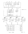
図4は、本実施形態に係る部品実装方法を適用できる生産ラインの一例を、この生産ラインのホストラインコンピュータ50の制御構成とともに模式的に示す図であり、図5は、この生産ラインを構成する部品実装装置10の制御構成を示すブロック図である。まず、図4および図5に示す構成について説明する。
FIG. 4 is a diagram schematically showing an example of a production line to which the component mounting method according to the present embodiment can be applied, together with the control configuration of the
ホストラインコンピュータ50は、製品(部品搭載基板)を製造するために必要な1つの生産ラインを構成する複数の部品実装装置10を管理し、該生産ラインを管理する。
The
ホストラインコンピュータ50は、図4に示すように、制御部61、データ出力部64、データ入力部65、データ記憶部66、データ送受信部67から構成されている。制御部61はCPU61a、RAM61b、ROM61cを有し、データ出力部(モニタ)64からはホストラインコンピュータ50が有するデータや演算結果等が出力される。
As shown in FIG. 4, the
また、キーボードなどの入力手段を介してデータ入力部65には生産プログラムデータなどが入力され、部品実装装置10からのデータはデータ送受信部67により受信される。これらのデータはデータ記憶部66に格納できるようになっている。RAM61b、ROM61c、或いはデータ記憶部66にはオペレーティングシステムプログラム(OS)や本実施形態を実行するためのプログラムや各種のデータが格納されている。
Further, production program data or the like is input to the
また、データ記憶部66には、用いるフィーダバンクFB1〜FBnにそれぞれ対応する吸着座標引継ぎファイルF1〜Fnが設けられている。実際の実装作業においては、フィーダバンクFBに取り付けられたフィーダ16の部品供給位置データを取得し、その結果に基づき、搭載ヘッドによる吸着目標位置の座標である吸着座標(取得目標位置座標)を補正するティーチングを行うが、補正された吸着座標(取得目標位置座標)は、用いるフィーダバンクFB1〜FBnにそれぞれ対応する吸着座標引継ぎファイルF1〜Fnに保存される。フィーダバンクFB1〜FBnは、部品実装装置10に取り付けられていないときはフィーダバンク置き場70に載置されており、部品搭載基板の生産に用いられるときに部品実装装置10に取り付けられる。
Further, the
なお、部品実装装置10において部品搭載基板を生産するために必要な各種データを含む生産プログラムデータは、完成された形でデータ入力部65を介してホストラインコンピュータ50に入力することができ、また、データ入力部65を介して入力された各種データに基づき、ホストラインコンピュータ50が各基板毎に作成することもできる。
Production program data including various data necessary for producing a component mounting board in the
部品実装装置10は、全体の部品実装を制御するCPU81a、各種制御プログラムやデータを格納したROM81c、制御データ、処理データを格納し作業領域を提供するRAM81bから構成される制御部81を有している。また、部品実装装置10には、ホストラインコンピュータ50との間でデータ送受信が可能なデータ送受信部86が設けられており、ホストラインコンピュータ50から送信されてくる生産プログラム、生産プログラムデータは、このデータ送受信部86を介して受信され、データ記憶部85に格納される。制御部81は、ホストラインコンピュータ50から送信される生産プログラム、生産プログラムデータ、並びにデータ入力部83を介して入力されるデータに従って、X/Y駆動部及びその他の駆動部82を駆動して、搭載ヘッドをフィーダ16の上方に移動させ、フィーダ16から供給される電子部品を搭載ヘッドに吸着させる。吸着された部品は、カメラを備えた画像認識部84で吸着姿勢が認識され、部品の向きが補正される。そして、基板搬送路(図示せず)に沿って搬送されて所定の位置でクランプされた基板の上方に搭載ヘッドが移動して、吸着した部品を基板上の所定位置に実装する。
The
ここで、前述のように、搭載ヘッドが部品を吸着する前に、フィーダバンクFBに取り付けられたフィーダ16の部品供給位置データを取得し、搭載ヘッドによる吸着目標位置の座標である吸着座標(取得目標位置座標)の補正をするティーチングを行うが、本実施形態に係る部品実装方法では、補正した吸着座標(取得目標位置座標)は、用いるフィーダバンクFB1〜FBnにそれぞれ対応する吸着座標引継ぎファイルF1〜Fnに、フィーダバンクFB1〜FBn毎に保存するので、生産プログラムデータの切り替えに伴いフィーダバンクFBを交換しても、交換後のフィーダバンクFBに対応する吸着座標引継ぎファイルFを読み出すことにより、フィーダ16の吸着座標(取得目標位置座標)のティーチング作業の回数を低減することができる。 Here, as described above, the component supply position data of the feeder 16 attached to the feeder bank FB is acquired before the mounting head sucks the component, and the suction coordinates (acquisition of the suction target position by the mounting head are acquired. Teaching is performed to correct (target position coordinates). In the component mounting method according to the present embodiment, the corrected suction coordinates (acquired target position coordinates) are taken over by the suction coordinates corresponding to the feeder banks FB 1 to FB n to be used. Since the files F 1 to F n are stored for each feeder bank FB 1 to FB n , even if the feeder bank FB is replaced when the production program data is switched, the adsorption coordinate transfer file corresponding to the replaced feeder bank FB By reading F, the number of teaching operations of the suction coordinates (acquired target position coordinates) of the feeder 16 can be reduced. Can.
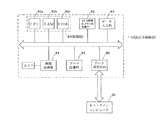
次に、このような効果をもたらす本実施形態に係る部品実装方法による処理手順を、図6に示すフローチャートに基づき説明する。 Next, a processing procedure by the component mounting method according to the present embodiment that brings about such an effect will be described based on a flowchart shown in FIG.
まず、実行する生産プログラムの生産プログラムデータを、ホストラインコンピュータ50に入力するか、あるいは入力データに基づきホストラインコンピュータ50内で作成して、ホストラインコンピュータ50の制御部61に記憶する(ステップS1)。ここで、生産プログラムデータにおいては、生産に用いるフィーダバンクFBに対応する吸着座標引継ぎファイルFをリンクさせておき(吸着座標引継ぎファイルFの番号1〜nをリンク番号にする)、吸着座標引継ぎファイルFに保存された吸着座標(取得目標位置座標)が生産プログラムデータに反映されるようにしておく。また、リンク番号ごとに、赤や青の色を設定しておき、該リンク番号に対応するフィーダバンクFBには、その番号と色が付されたシールを貼るなどして、その番号と色を表示しておく。
First, production program data of a production program to be executed is input to the
次に、制御部61は、吸着座標引継ぎファイルFに保存された吸着座標(取得目標位置座標)を生産プログラムデータに反映させる処理を行うが、具体的には、まず、生産プログラムデータにリンクされた吸着座標引継ぎファイルFを選択する(ステップS2)。そして、選択した吸着座標引継ぎファイルFに保存された吸着座標(取得目標位置座標)の値を、生産プログラムデータの吸着座標(取得目標位置座標)に反映させる(ステップS3)。また、ホストラインコンピュータ50のデータ出力部(生産画面)64には、リンク番号とその番号に対応した色を表示させる(ステップS4)。フィーダバンクFBに、対応する吸着座標引継ぎファイルFの番号と色が付されたシールを貼るなどすることにより、部品実装装置10に取り付けるべきフィーダバンクFBを作業者が見出しやすいようにすることができる。これにより、フィーダバンクFBの掛け違いも防止することができる。なお、生産プログラムデータに吸着座標引継ぎファイルFがリンクされていないときは、使用する吸着座標引継ぎファイルFを指定できるようにしておく。
Next, the control unit 61 performs processing for reflecting the suction coordinates (acquired target position coordinates) stored in the suction coordinate takeover file F in the production program data. Specifically, first, the control unit 61 is linked to the production program data. The adsorption coordinate takeover file F is selected (step S2). Then, the value of the suction coordinates (acquisition target position coordinates) stored in the selected suction coordinate takeover file F is reflected in the suction coordinates (acquisition target position coordinates) of the production program data (step S3). The data output unit (production screen) 64 of the
そして、吸着座標引継ぎファイルFに保存された吸着座標(取得目標位置座標)の値が反映された生産プログラムデータを、ホストラインコンピュータ50から部品実装装置10へダウンロードする(ステップS5)。ダウンロードした生産プログラムデータに吸着座標(取得目標位置座標)のデータが含まれていないフィーダ16については、吸着座標のティーチングを行って生産プログラムデータに反映させて(ステップS6)、部品搭載基板の生産を開始する(ステップS7)。
Then, the production program data reflecting the value of the suction coordinates (acquired target position coordinates) stored in the suction coordinate takeover file F is downloaded from the
このように、本実施形態に係る部品実装方法では、生産プログラムデータの切り替えに伴いフィーダバンクFBを交換しても、吸着座標(取得目標位置座標)のティーチングを行う必要のあるフィーダ16は、吸着座標引継ぎファイルFに吸着座標(取得目標位置座標)のデータのないフィーダだけであり、限られたフィーダ16についてだけティーチングを行えばよいので、ティーチング作業の回数を低減することができる。 As described above, in the component mounting method according to the present embodiment, even if the feeder bank FB is replaced with the switching of the production program data, the feeder 16 that needs to perform teaching of the suction coordinates (acquired target position coordinates) is Since only the feeders that do not have the adsorption coordinates (acquired target position coordinates) data in the coordinate takeover file F and only a limited number of feeders 16 need to be taught, the number of teaching operations can be reduced.
部品搭載基板の生産が終了したら(ステップS8)、ティーチングを行って得られた吸着座標(取得目標位置座標)が反映された生産プログラムデータをアップロードする(ステップS9)。 When the production of the component mounting board is completed (step S8), the production program data reflecting the suction coordinates (acquired target position coordinates) obtained by teaching is uploaded (step S9).
そして、制御部61は、アップロードされた生産プログラムデータの吸着座標(取得目標位置座標)のデータを吸着座標引継ぎファイルFに反映させて保存する処理を行うが、具体的には、まず、生産プログラムデータにリンクされた吸着座標引継ぎファイルFを選択する(ステップS10)。そして、生産プログラムデータの吸着座標(取得目標位置座標)のデータを、選択した吸着座標引継ぎファイルFに反映させて保存する(ステップS11)。さらに、新旧の生産プログラムデータを結合して保存する(ステップS12)。 Then, the control unit 61 performs processing to reflect and save the suction coordinate (acquired target position coordinate) data of the uploaded production program data in the suction coordinate takeover file F. Specifically, first, the production program The adsorption coordinate takeover file F linked to the data is selected (step S10). Then, the suction coordinate (acquired target position coordinates) data of the production program data is reflected in the selected suction coordinate takeover file F and stored (step S11). Further, the old and new production program data are combined and stored (step S12).
次の生産プログラムがあればステップS1にもどって部品搭載基板の生産を行い、次の生産プログラムがなければ一連の処理を終了する(ステップS13)。 If there is a next production program, the process returns to step S1 to produce the component-mounted board, and if there is no next production program, the series of processes is terminated (step S13).
以上説明したように、本実施形態に係る部品実装方法では、吸着座標引継ぎファイルFがフィーダバンクFBごとに設けられて、使い分けられているので、一度ティーチングして得られた吸着座標(取得目標位置座標)のデータはフィーダバンクFBごとにそれぞれ対応する吸着座標引継ぎファイルFに保持される。このため、生産プログラムデータの変更に伴ってフィーダバンクFBが交換されても、対応する吸着座標引継ぎファイルFに吸着座標データが保存されていないフィーダ16のみをティーチングすればよく、段取り時間を短縮することができる。 As described above, in the component mounting method according to the present embodiment, since the suction coordinate takeover file F is provided for each feeder bank FB and is used properly, the suction coordinates (acquired target position) obtained by teaching once. (Coordinate) data is held in the suction coordinate takeover file F corresponding to each feeder bank FB. For this reason, even if the feeder bank FB is exchanged as the production program data is changed, it is only necessary to teach the feeder 16 whose suction coordinate data is not stored in the corresponding suction coordinate takeover file F, thereby shortening the setup time. be able to.
また、生産プログラムデータにおいて、生産に用いるフィーダバンクFBに対応する吸着座標引継ぎファイルFがリンクされているので、生産プログラムデータと吸着座標引継ぎファイルFとの間で吸着座標(取得目標位置座標)のデータを照合して、最新の吸着座標(取得目標位置座標)にしておくことが容易である。 Further, in the production program data, since the adsorption coordinate takeover file F corresponding to the feeder bank FB used for production is linked, the adsorption coordinates (acquisition target position coordinates) are set between the production program data and the adsorption coordinate takeover file F. It is easy to collate the data and keep the latest adsorption coordinates (acquisition target position coordinates).
また、吸着座標引継ぎファイルFとフィーダバンクFBとを色や番号でリンク付けしておき、生産に用いるフィーダバンクFBの色と番号を生産画面に表示することで、生産に用いるフィーダバンクFBが視覚的にわかるため、フィーダバンクの切り替え時間を短縮することができるとともに、フィーダバンクFBの掛け違いを防止することができる。 Also, the suction coordinate transfer file F and the feeder bank FB are linked by color and number, and the color and number of the feeder bank FB used for production are displayed on the production screen, so that the feeder bank FB used for production is visually recognized. Therefore, it is possible to shorten the feeder bank switching time and to prevent the feeder bank FB from being overlaid.
なお、本実施形態に係る部品実装方法は、フィーダ16がフィーダバンクFBに取り付け固定されて部品の供給がなされる部品実装装置であれば適用することができ、このような部品実装装置であれば部品実装装置の搭載ヘッドの数は1つでも複数でもよい。また、該搭載ヘッドが部品を保持する方法は吸着でなくてもよく、例えば部品を両側から挟みこんで保持する方法であってもよい。 Note that the component mounting method according to the present embodiment can be applied to any component mounting apparatus in which the feeder 16 is attached and fixed to the feeder bank FB to supply components. The number of mounting heads of the component mounting apparatus may be one or plural. Further, the method of holding the component by the mounting head may not be suction, and for example, a method of holding the component by sandwiching it from both sides may be used.
また、用いる生産プログラムデータは、クラスタ化されていてもいなくても用いることができるが、クラスタ化されていることが好ましい。 The production program data to be used can be used regardless of whether it is clustered or not, but is preferably clustered.
また、生産に用いる生産プログラムデータに使用されていないフィーダバンクFBがフィーダバンク置き場70に載置されていても、本実施形態に係る部品実装方法を用いることができ、吸着座標引継ぎファイルFとフィーダバンクFBとが色や番号でリンク付けされている場合には、生産に用いないフィーダバンクFBがフィーダバンク置き場70に載置されていても、必要なフィーダバンクFBを見出しやすく、フィーダバンクFBの切り替え時間を短縮することができるとともに、フィーダバンクFBの掛け違いを防止することができる。 Even if a feeder bank FB that is not used in production program data used for production is placed in the feeder bank storage place 70, the component mounting method according to the present embodiment can be used, and the suction coordinate takeover file F and the feeder are used. When the bank FB is linked by color or number, even if a feeder bank FB not used for production is placed in the feeder bank storage place 70, it is easy to find the necessary feeder bank FB. The switching time can be shortened and the feeder bank FB can be prevented from being overlaid.
10…部品実装装置
12…本体部
14…部品供給部
16…フィーダ
20…交換台車
30…上昇位置決め装置
40…位置決め部
50…ホストラインコンピュータ
61…制御部
64…データ出力部
65…データ入力部
66…データ記憶部
67…データ送受信部
70…フィーダバンク置き場
F…吸着座標引継ぎファイル
FB…フィーダバンク
DESCRIPTION OF
Claims (1)
前記ティーチングにより補正された前記取得目標位置座標を保存する引継ぎファイルをフィーダバンクごとに設け、フィーダバンクを切り換える際、該引継ぎファイルに保存された該取得目標位置座標を反映させた生産プログラムデータを部品実装装置にダウンロードすることを特徴とする部品実装方法。 In the component mounting method of performing teaching for correcting the acquisition target position coordinates of the component supplied from the feeder mounted on the feeder bank and mounting the component at a predetermined position on the board,
A takeover file that stores the acquired target position coordinates corrected by the teaching is provided for each feeder bank, and when the feeder bank is switched, the production program data that reflects the acquired target position coordinates stored in the takeover file is a component. A component mounting method comprising downloading to a mounting apparatus.
Priority Applications (2)
| Application Number | Priority Date | Filing Date | Title |
|---|---|---|---|
| JP2008226681A JP5165507B2 (en) | 2008-09-04 | 2008-09-04 | Component mounting method |
| CN200910172915.XA CN101668415B (en) | 2008-09-04 | 2009-09-03 | Component installation method and component installation system |
Applications Claiming Priority (1)
| Application Number | Priority Date | Filing Date | Title |
|---|---|---|---|
| JP2008226681A JP5165507B2 (en) | 2008-09-04 | 2008-09-04 | Component mounting method |
Publications (2)
| Publication Number | Publication Date |
|---|---|
| JP2010062343A true JP2010062343A (en) | 2010-03-18 |
| JP5165507B2 JP5165507B2 (en) | 2013-03-21 |
Family
ID=41804767
Family Applications (1)
| Application Number | Title | Priority Date | Filing Date |
|---|---|---|---|
| JP2008226681A Active JP5165507B2 (en) | 2008-09-04 | 2008-09-04 | Component mounting method |
Country Status (2)
| Country | Link |
|---|---|
| JP (1) | JP5165507B2 (en) |
| CN (1) | CN101668415B (en) |
Cited By (2)
| Publication number | Priority date | Publication date | Assignee | Title |
|---|---|---|---|---|
| CN103766017A (en) * | 2011-09-27 | 2014-04-30 | 富士机械制造株式会社 | Electronic component supply device |
| JP2017045805A (en) * | 2015-08-25 | 2017-03-02 | ヤマハ発動機株式会社 | Exchange truck and surface mounting machine |
Families Citing this family (4)
| Publication number | Priority date | Publication date | Assignee | Title |
|---|---|---|---|---|
| JP5721509B2 (en) * | 2011-04-13 | 2015-05-20 | 富士機械製造株式会社 | Component mounter |
| JP6092517B2 (en) * | 2012-01-31 | 2017-03-08 | ヤマハ発動機株式会社 | Electronic component mounting method, electronic component mounting apparatus, and component library data teaching method |
| DE102015122931A1 (en) * | 2015-12-29 | 2017-06-29 | Asm Assembly Systems Gmbh & Co. Kg | Method for creating a production line and system for assembling a board with components |
| EP3484258B1 (en) * | 2016-07-08 | 2020-12-02 | Fuji Corporation | Component-mounting system and management device |
Citations (2)
| Publication number | Priority date | Publication date | Assignee | Title |
|---|---|---|---|---|
| JP2002151888A (en) * | 2000-11-10 | 2002-05-24 | Juki Corp | Electronic element mounting apparatus and feeder bank |
| JP2002176296A (en) * | 2000-12-06 | 2002-06-21 | Yamagata Casio Co Ltd | Mounting data generating device and recording medium of program |
Family Cites Families (1)
| Publication number | Priority date | Publication date | Assignee | Title |
|---|---|---|---|---|
| JP4387842B2 (en) * | 2004-03-16 | 2009-12-24 | 株式会社日立ハイテクインスツルメンツ | Backup pin positioning jig and back-up pin setup method |
-
2008
- 2008-09-04 JP JP2008226681A patent/JP5165507B2/en active Active
-
2009
- 2009-09-03 CN CN200910172915.XA patent/CN101668415B/en active Active
Patent Citations (2)
| Publication number | Priority date | Publication date | Assignee | Title |
|---|---|---|---|---|
| JP2002151888A (en) * | 2000-11-10 | 2002-05-24 | Juki Corp | Electronic element mounting apparatus and feeder bank |
| JP2002176296A (en) * | 2000-12-06 | 2002-06-21 | Yamagata Casio Co Ltd | Mounting data generating device and recording medium of program |
Cited By (3)
| Publication number | Priority date | Publication date | Assignee | Title |
|---|---|---|---|---|
| CN103766017A (en) * | 2011-09-27 | 2014-04-30 | 富士机械制造株式会社 | Electronic component supply device |
| CN103766017B (en) * | 2011-09-27 | 2017-05-24 | 富士机械制造株式会社 | Electronic component supply device |
| JP2017045805A (en) * | 2015-08-25 | 2017-03-02 | ヤマハ発動機株式会社 | Exchange truck and surface mounting machine |
Also Published As
| Publication number | Publication date |
|---|---|
| CN101668415A (en) | 2010-03-10 |
| CN101668415B (en) | 2014-05-14 |
| JP5165507B2 (en) | 2013-03-21 |
Similar Documents
| Publication | Publication Date | Title |
|---|---|---|
| JP5165507B2 (en) | Component mounting method | |
| KR101153491B1 (en) | Checking method of parts mounting error and checking system of parts mounting error | |
| US10893641B2 (en) | Group determination method and group determination apparatus | |
| US10520930B2 (en) | Component mounting system and progress display system of set-up work | |
| CN107872948B (en) | Version upgrading method for program in component mounting production line | |
| WO2014049873A1 (en) | Device for correcting image processing data, and method for correcting image processing data | |
| JP2007158050A (en) | Adjustment system of tape feeder | |
| JP6467634B2 (en) | Component mounting system and component mounting method in component mounting system | |
| KR20120070517A (en) | Electronic component mounting apparatus, and electronic component mounting method | |
| US10793388B2 (en) | Feeder arrangement support system and method for supporting feeder arrangement | |
| JP2007158049A (en) | Adjustment apparatus for tape feeder | |
| US20220087087A1 (en) | Management device, moving work device, mounting device, mounting system, and management method | |
| JP2014241373A (en) | Substrate work machine | |
| JP4674534B2 (en) | How to adjust the tape feeder | |
| JP2019186454A (en) | Work assistance device | |
| JP4903615B2 (en) | Component mounting system | |
| JP2015002230A (en) | Electronic component packaging device and electronic component packaging system | |
| JP6424236B2 (en) | Anti-substrate work management device | |
| JP2010010272A (en) | Component mounting device, and component mounting method | |
| JP6630729B2 (en) | Component mounting system | |
| JP6368215B2 (en) | Component mounting apparatus, surface mounter, and component mounting method | |
| JP2004319943A (en) | Component mounting device and component mounting method | |
| JP6947931B2 (en) | Parts supply unit placement determination method and parts mounting system | |
| JP2012119511A (en) | Electronic component mounting device, electronic component mounting system, and electronic component mounting method | |
| JP5386382B2 (en) | Electronic component mounting device with check function for on-board camera |
Legal Events
| Date | Code | Title | Description |
|---|---|---|---|
| A621 | Written request for application examination |
Free format text: JAPANESE INTERMEDIATE CODE: A621 Effective date: 20110831 |
|
| A977 | Report on retrieval |
Free format text: JAPANESE INTERMEDIATE CODE: A971007 Effective date: 20120817 |
|
| A131 | Notification of reasons for refusal |
Free format text: JAPANESE INTERMEDIATE CODE: A131 Effective date: 20120821 |
|
| A521 | Written amendment |
Free format text: JAPANESE INTERMEDIATE CODE: A523 Effective date: 20121015 |
|
| TRDD | Decision of grant or rejection written | ||
| A01 | Written decision to grant a patent or to grant a registration (utility model) |
Free format text: JAPANESE INTERMEDIATE CODE: A01 Effective date: 20121120 |
|
| A61 | First payment of annual fees (during grant procedure) |
Free format text: JAPANESE INTERMEDIATE CODE: A61 Effective date: 20121219 |
|
| FPAY | Renewal fee payment (event date is renewal date of database) |
Free format text: PAYMENT UNTIL: 20151228 Year of fee payment: 3 |
|
| R150 | Certificate of patent or registration of utility model |
Ref document number: 5165507 Country of ref document: JP Free format text: JAPANESE INTERMEDIATE CODE: R150 Free format text: JAPANESE INTERMEDIATE CODE: R150 |