JP2010061386A - Paper sheet storage cassette and paper sheet handling apparatus - Google Patents
Paper sheet storage cassette and paper sheet handling apparatus Download PDFInfo
- Publication number
- JP2010061386A JP2010061386A JP2008226262A JP2008226262A JP2010061386A JP 2010061386 A JP2010061386 A JP 2010061386A JP 2008226262 A JP2008226262 A JP 2008226262A JP 2008226262 A JP2008226262 A JP 2008226262A JP 2010061386 A JP2010061386 A JP 2010061386A
- Authority
- JP
- Japan
- Prior art keywords
- paper sheet
- shaft
- paper
- storage cassette
- sheet storage
- Prior art date
- Legal status (The legal status is an assumption and is not a legal conclusion. Google has not performed a legal analysis and makes no representation as to the accuracy of the status listed.)
- Granted
Links
Images


Landscapes
- Pile Receivers (AREA)
Abstract
Description
本発明は、紙幣や小切手等の紙葉類の収納を行う紙葉類収納カセットおよびこの紙葉類収納カセットを備えた紙葉類処理装置に関し、とりわけ、紙葉類収納カセットを紙葉類処理装置から取り外したときに、紙葉類収納部に収納された紙葉類が盗難者等により抜き取られることを防止することができるとともに、収納繰出機構のローラが設けられた箇所において紙葉類の詰まりが発生した場合でもこのような紙葉類の詰まりを解消することができる紙葉類収納カセットおよび紙葉類処理装置に関する。 The present invention relates to a paper sheet storage cassette that stores paper sheets such as banknotes and checks, and a paper sheet processing apparatus including the paper sheet storage cassette, and more particularly, to a paper sheet processing cassette. It is possible to prevent the paper sheets stored in the paper sheet storage unit from being pulled out by a thief or the like when removed from the apparatus, and at the place where the roller of the storage feeding mechanism is provided, The present invention relates to a paper sheet storage cassette and a paper sheet processing apparatus that can eliminate such a paper sheet clogging even when the paper jam occurs.
従来より、紙幣や小切手等の紙葉類の収納や投出を行う紙葉類処理装置に、紙葉類収納カセットが着脱自在に収容されていることが知られている。このような紙葉類収納カセットは、略直方体形状の筐体と、筐体の上面に設けられ、当該筐体の外部から内部への紙葉類の投入および筐体の内部から外部への紙葉類の投出を行うための投出入口と、筐体の内部に設けられ、投出入口により筐体の外部から内部に投入された紙葉類が収納される紙葉類収納部と、を備えている。 Conventionally, it is known that a paper sheet storage cassette is detachably accommodated in a paper sheet processing apparatus that stores and throws out paper sheets such as banknotes and checks. Such a paper sheet storage cassette is provided on a substantially rectangular parallelepiped housing and an upper surface of the housing, and a paper sheet is inserted into the housing from the outside to the inside and paper from the inside of the housing to the outside. A discharge inlet for discharging the leaves, and a paper sheet storage unit that is provided inside the housing and stores paper sheets that are input from the outside of the housing through the discharge inlet. ing.
従来の紙葉類収納カセットでは、紙葉類収納部に収納された紙葉類を投出入口に繰り出すような収納繰出機構が筐体の内部に設けられていないタイプのものがあった。このようなタイプの紙葉類収納カセットでは、収納繰出機構が設けられる代わりにシャッター機構が投出入口に設けられており、このシャッター機構により投出入口の開閉を行うようになっている。そして、紙葉類収納カセットの筐体の内部から外部へ紙葉類の投出を行う際には、紙葉類収納カセットのシャッター機構により投出入口を開いた後、紙葉類処理装置に設けられた収納繰出機構によって紙葉類収納カセットの紙葉類収納部に収納された紙葉類の繰り出しを行うようになっている。 Some conventional paper sheet storage cassettes are not provided with a storage / feeding mechanism for feeding paper sheets stored in a paper sheet storage section to the outlet. In such a type of paper sheet storage cassette, a shutter mechanism is provided at a discharge inlet instead of a storage and feeding mechanism, and the shutter opening mechanism opens and closes the discharge inlet. When paper sheets are ejected from the inside of the housing of the paper sheet storage cassette to the outside, the paper entrance is opened by the shutter mechanism of the paper sheet storage cassette and then provided in the paper sheet processing apparatus. The stored paper feed mechanism feeds out the paper sheets stored in the paper sheet storage section of the paper sheet storage cassette.
また、従来の紙葉類収納カセットにおいて、紙葉類収納部に収納された紙葉類を投出入口に繰り出すような収納繰出機構が筐体の内部に設けられているタイプのものもある。このようなタイプの紙葉類収納カセットでは、収納繰出機構は、投出入口により筐体の外部から内部に投入された紙葉類を紙葉類収納部に送るとともにこの紙葉類収納部に収納された紙葉類を投出入口に繰り出すようになっている。ここで、収納繰出機構は、筐体の上面に設けられた投出入口の近傍に設置されている。 In addition, there is a type of conventional paper sheet storage cassette in which a storage and feeding mechanism is provided inside the housing so as to feed the paper sheets stored in the paper sheet storage unit to the outlet. In this type of paper sheet storage cassette, the storage and feeding mechanism sends the paper sheet that has been input from the outside of the housing through the outlet into the paper sheet storage section and stores it in the paper sheet storage section. The paper sheets that have been used are fed out to the outlet. Here, the storing and feeding mechanism is installed in the vicinity of the dispensing inlet provided on the upper surface of the housing.
収納繰出機構が筐体の内部に設けられているような紙葉類収納カセットでは、例えば特許文献1等に示すように、収納繰出機構を構成するローラの近傍にこのローラの回転を規制するためのロック機構が設けられている。そして、紙葉類収納カセットが紙葉類処理装置に装着された場合は、ロック機構はローラを紙葉類の投入方向および投出方向の両方向に回転させ、一方、紙葉類収納カセットが紙葉類処理装置から取り外された場合は、ロック機構はローラを回転させないようになっている。このことにより、紙葉類収納カセットが紙葉類処理装置から取り外されたときには、この紙葉類収納カセットの紙葉類収納部に収納された紙葉類を投出入口から抜き取ることができないようになっている。 In the paper sheet storage cassette in which the storage and feeding mechanism is provided inside the housing, for example, as shown in Patent Document 1 or the like, in order to regulate the rotation of this roller in the vicinity of the roller constituting the storage and feeding mechanism. A locking mechanism is provided. When the paper sheet storage cassette is attached to the paper sheet processing apparatus, the lock mechanism rotates the roller in both the paper feeding direction and the paper feeding direction, while the paper sheet storage cassette is When removed from the leaf processing apparatus, the lock mechanism does not rotate the roller. Thus, when the paper sheet storage cassette is removed from the paper sheet processing apparatus, the paper sheets stored in the paper sheet storage section of the paper sheet storage cassette cannot be extracted from the outlet. It has become.
しかしながら、収納繰出機構が紙葉類収納カセットの筐体の内部に設けられておらず、シャッター機構が紙葉類収納カセットの投出入口に設けられているようなタイプの紙葉類収納カセットにおいては、シャッター機構は故障しがちでありこのシャッター機構は様々なトラブルの原因になりやすいという問題がある。また、このような紙葉類収納カセットでは、紙葉類収納カセットのシャッター機構により投出入口を開いた後、紙葉類処理装置に設けられた収納繰出機構によって紙葉類収納カセットの紙葉類収納部に収納された紙葉類の繰り出しを行うようになっているが、このような収納繰出機構による紙葉類の繰り出し方法は様々なトラブルの原因になりやすいという問題がある。 However, in the paper sheet storage cassette of the type in which the storage and feeding mechanism is not provided in the housing of the paper sheet storage cassette and the shutter mechanism is provided at the outlet of the paper sheet storage cassette. The shutter mechanism tends to break down, and this shutter mechanism has a problem that it easily causes various troubles. Further, in such a paper sheet storage cassette, after opening the outlet / inlet by the shutter mechanism of the paper sheet storage cassette, the paper sheet of the paper sheet storage cassette is stored by the storage feeding mechanism provided in the paper sheet processing apparatus. Although the paper sheets stored in the storage section are fed out, there is a problem that the paper sheet feeding method by such a storage and feeding mechanism tends to cause various troubles.
また、例えば特許文献1等に示すような紙葉類収納カセットにおいては、収納繰出機構のローラが設けられた箇所において紙葉類の詰まり(ジャム)が発生した場合に、紙葉類収納カセットを紙葉類処理装置から取り外すとこのローラはロック機構により完全に固定されるため、この詰まりが発生した紙葉類を収納繰出機構から手動で取り出すことが困難であるという問題がある。このため、このタイプの紙葉類収納カセットには、収納繰出機構のローラが設けられた箇所で詰まりが発生した紙葉類を収納繰出機構から取り出すための専用の機構を別途設けなければならない。 For example, in a paper sheet storage cassette as shown in Patent Document 1 or the like, when a paper sheet jam occurs at a position where a roller of the storage and feeding mechanism is provided, the paper sheet storage cassette is When the roller is removed from the paper sheet processing apparatus, the roller is completely fixed by the lock mechanism, and there is a problem that it is difficult to manually take out the paper sheet in which the jam has occurred from the storing and feeding mechanism. For this reason, this type of paper sheet storage cassette must be provided with a dedicated mechanism for taking out from the storage and feeding mechanism a paper sheet that has become clogged at a position where the roller of the storage and feeding mechanism is provided.
また、上述のような紙葉類収納カセットにおいて、収納繰出機構のローラの回転を規制するためのロック機構を設けなかった場合には、紙葉類収納カセットを紙葉類処理装置から取り外した場合でもローラは紙葉類の投入方向および投出方向の両方向に自在に回転することができるようになるため、紙葉類の投出方向にローラを回転させれば誰でも紙葉類収納カセットの紙葉類収納部に収納された紙葉類を抜き取ることができるようになり、防犯上問題があった。 Further, in the paper sheet storage cassette as described above, when the lock mechanism for restricting the rotation of the rollers of the storage and feeding mechanism is not provided, the paper sheet storage cassette is removed from the paper sheet processing apparatus. However, since the roller can freely rotate in both the paper feeding direction and the paper feeding direction, anyone can rotate the paper in the paper feeding direction. The paper sheets stored in the paper sheet storage section can be extracted, which causes a problem in crime prevention.
本発明は、このような点を考慮してなされたものであり、紙葉類収納カセットを紙葉類処理装置から取り外したときに、ローラを紙葉類の投出方向に回転させることができなくなるため紙葉類収納部に収納された紙葉類が例えば盗難者等により抜き取られることを防止することができ、また、収納繰出機構のローラが設けられた箇所において紙葉類の詰まりが発生した場合でも、紙葉類収納カセットを紙葉類処理装置から取り外した後、ローラを紙葉類の投入方向に回転させることによりこのような紙葉類の詰まりを解消することができる紙葉類収納カセットおよびこの紙葉類収納カセットを備えた紙葉類処理装置を提供することを目的とする。 The present invention has been made in consideration of such points, and when the paper sheet storage cassette is removed from the paper sheet processing apparatus, the roller can be rotated in the paper sheet ejection direction. Therefore, the paper sheets stored in the paper sheet storage unit can be prevented from being pulled out by, for example, the theft, and the paper sheets are clogged at the location where the rollers of the storage and feeding mechanism are provided. Even in such a case, after removing the paper sheet storage cassette from the paper sheet processing apparatus, the paper sheet can be cleared by rotating the roller in the paper loading direction. It is an object of the present invention to provide a storage cassette and a paper sheet processing apparatus including the paper sheet storage cassette.
本発明の紙葉類収納カセットは、紙葉類の処理を行う紙葉類処理装置に着脱自在に収容される紙葉類収納カセットであって、筐体と、前記筐体の外部から内部への紙葉類の投入および前記筐体の内部から外部への紙葉類の投出を行うための投出入口と、前記筐体の内部に設けられ、前記投出入口により前記筐体の外部から内部に投入された紙葉類が収納される紙葉類収納部と、前記筐体の内部に設けられ、前記投出入口により前記筐体の外部から内部に投入された紙葉類を前記紙葉類収納部に送るとともに前記紙葉類収納部に収納された紙葉類を前記投出入口に繰り出すローラを有する収納繰出機構と、前記収納繰出機構のローラの回転を規制するローラ回転規制機構であって、前記紙葉類収納カセットが前記紙葉類処理装置に装着されたときには前記ローラを紙葉類の投入方向および投出方向の両方向に回転させ、前記紙葉類収納カセットが前記紙葉類処理装置から取り外されたときには前記ローラを紙葉類の投入方向のみに回転させるよう前記ローラの回転を規制するようなローラ回転規制機構と、を備えたことを特徴とする。 The paper sheet storage cassette according to the present invention is a paper sheet storage cassette that is detachably stored in a paper sheet processing apparatus that processes paper sheets, from the outside of the housing to the inside. A paper inlet for discharging paper sheets and discharging paper sheets from the inside of the housing to the outside, and an inside of the housing provided by the inside of the housing from the outside of the housing A paper sheet storage unit that stores paper sheets that are input into the housing, and a paper sheet that is provided inside the casing and is input into the casing from the outside through the outlet port. A storage / feeding mechanism having a roller for feeding the paper sheets stored in the paper sheet storage unit to the storage unit, and a roller rotation regulating mechanism for regulating rotation of the rollers of the storage / feeding mechanism; The paper sheet storage cassette is mounted on the paper sheet processing apparatus. The roller is rotated in both the paper feeding direction and the paper feeding direction, and when the paper sheet storage cassette is removed from the paper sheet processing apparatus, the roller is moved only in the paper feeding direction. And a roller rotation restricting mechanism for restricting the rotation of the roller to rotate.
このような紙葉類収納カセットによれば、ローラ回転規制機構は、紙葉類収納カセットが紙葉類処理装置に装着されたときにはローラを紙葉類の投入方向および投出方向の両方向に回転させ、一方、紙葉類収納カセットが紙葉類処理装置から取り外されたときにはローラを紙葉類の投入方向のみに回転させるようローラの回転を規制する。このため、紙葉類収納カセットを紙葉類処理装置から取り外したときにローラを紙葉類の投出方向に回転させることができなくなるため紙葉類収納部に収納された紙葉類が例えば盗難者等により抜き取られることを防止することができる。また、収納繰出機構のローラが設けられた箇所において紙葉類の詰まりが発生した場合でも、紙葉類収納カセットを紙葉類処理装置から取り外した後、ローラを紙葉類の投入方向に例えば手動で回転させることによりこのような紙葉類の詰まりを解消することができる。 According to such a paper sheet storage cassette, the roller rotation restricting mechanism rotates the roller in both the paper feeding direction and the paper feeding direction when the paper sheet storage cassette is mounted on the paper sheet processing apparatus. On the other hand, when the paper sheet storage cassette is removed from the paper sheet processing apparatus, the rotation of the roller is restricted so that the roller rotates only in the paper sheet loading direction. For this reason, when the paper sheet storage cassette is removed from the paper sheet processing apparatus, the rollers cannot be rotated in the paper sheet discharge direction, so that the paper sheets stored in the paper sheet storage unit are, for example, It can be prevented from being extracted by a theft or the like. Further, even when a paper sheet is jammed at the location where the roller of the storage and feeding mechanism is provided, after removing the paper sheet storage cassette from the paper sheet processing apparatus, the roller is inserted in the paper loading direction, for example. By manually rotating the paper sheet, it is possible to eliminate such paper jams.
本発明の紙葉類収納カセットにおいては、前記ローラ回転規制機構は、前記収納繰出機構の前記ローラと同期して回転する軸と、前記軸の近傍において移動自在に設けられたロック部材とを有し、前記紙葉類収納カセットが前記紙葉類処理装置に収容されたときには前記ロック部材は前記軸から離間し、前記紙葉類収納カセットが前記紙葉類処理装置から取り外されたときには前記ロック部材は前記軸に係合し、前記ロック部材は、前記軸が係合されたときにこの軸を紙葉類の投入方向には回転させるが紙葉類の投出方向には回転させないような形状となっていることが好ましい。このような紙葉類収納カセットによれば、収納繰出機構のローラの回転を規制するローラ回転規制機構の構成をシンプルなものとすることができる。 In the paper sheet storage cassette of the present invention, the roller rotation restricting mechanism includes a shaft that rotates in synchronization with the roller of the storage and feeding mechanism, and a lock member that is provided movably in the vicinity of the shaft. When the paper sheet storage cassette is stored in the paper sheet processing apparatus, the lock member is separated from the shaft, and when the paper sheet storage cassette is removed from the paper sheet processing apparatus, the lock member is separated. The member engages with the shaft, and the lock member rotates the shaft in the paper feeding direction but does not rotate in the paper feeding direction when the shaft is engaged. A shape is preferred. According to such a paper sheet storage cassette, the configuration of the roller rotation regulating mechanism that regulates the rotation of the rollers of the storage and feeding mechanism can be simplified.
この場合、前記ロック部材は凹部を有し、前記紙葉類収納カセットが前記紙葉類処理装置から取り外されたときには前記軸は前記ロック部材の凹部に挿入されるようになっており、前記凹部は、前記軸が挿入されたときにこの軸を紙葉類の投入方向には回転させるが紙葉類の投出方向には回転させないような形状となっていることがより好ましい。 In this case, the lock member has a recess, and the shaft is inserted into the recess of the lock member when the sheet storage cassette is removed from the sheet processing apparatus. More preferably, when the shaft is inserted, the shaft is rotated in the paper feeding direction but not rotated in the paper feeding direction.
ここで、前記軸は、前記ロック部材の凹部に挿入されたときにこの凹部に接触する箇所において周方向において部分的に平面形状となっており、前記凹部は、前記軸が挿入された際にこの軸と略平行に延びる互いに対向する第1の側面部分および第2の側面部分とを有し、第1の側面部分は略平面形状となっており、第2の側面部分は前記凹部の開口部分に向かって広がるようなテーパ形状となっており、前記軸が紙葉類の投出方向に回転しようとしたときにこの軸の平面形状部分が前記凹部の第1の側面部分に当接することにより当該軸の回転が規制され、前記軸が紙葉類の投入方向に回転しようとしたときにこの軸の平面形状部分が前記凹部の第2の側面部分に当接することにより当該軸の回転が許容されるようになっていることが更に好ましい。 Here, when the shaft is inserted into the recess of the lock member, the shaft is partially planar in the circumferential direction at a location where the shaft comes into contact with the recess, and the recess is formed when the shaft is inserted. The first side surface portion and the second side surface portion facing each other extend substantially parallel to the axis, the first side surface portion has a substantially planar shape, and the second side surface portion is an opening of the recess. It has a tapered shape that spreads toward the portion, and when the shaft is about to rotate in the paper discharge direction, the planar portion of this shaft abuts on the first side surface portion of the recess. The rotation of the shaft is restricted by this, and when the shaft is about to rotate in the sheet loading direction, the planar shape portion of the shaft comes into contact with the second side surface portion of the concave portion, thereby rotating the shaft. To be allowed Masui.
また、前記紙葉類収納カセットには、当該紙葉類収納カセットが前記紙葉類処理装置に収容されたときにこの紙葉類処理装置に設けられたラック部材と噛み合うようなピニオン部材が設けられており、前記ピニオン部材は前記ローラ回転規制機構のロック部材と接続されており、前記ピニオン部材が前記ラック部材と噛み合って回転することにより前記ロック部材が移動するようになっていることが好ましい。 The paper sheet storage cassette is provided with a pinion member that meshes with a rack member provided in the paper sheet processing apparatus when the paper sheet storage cassette is stored in the paper sheet processing apparatus. Preferably, the pinion member is connected to a lock member of the roller rotation regulating mechanism, and the lock member moves when the pinion member meshes with the rack member and rotates. .
この場合、前記ピニオン部材が前記ラック部材と噛み合っていないときには前記ロック部材は前記軸に係合しており、前記ピニオン部材が前記ラック部材と噛み合って回転したときに前記ロック部材は前記軸から離間するよう移動するようになっていることが好ましい。 In this case, when the pinion member is not engaged with the rack member, the lock member is engaged with the shaft, and when the pinion member is engaged with the rack member and rotated, the lock member is separated from the shaft. It is preferable to move so as to.
本発明の紙葉類処理装置は、紙葉類の収納や投出を行う紙葉類処理装置であって、上述した紙葉類収納カセットを備えたことを特徴とする。 The paper sheet processing apparatus of the present invention is a paper sheet processing apparatus for storing and dispensing paper sheets, and includes the above-described paper sheet storage cassette.
本発明の紙葉類収納カセットおよびこの紙葉類収納カセットを備えた紙葉類処理装置によれば、紙葉類収納カセットを紙葉類処理装置から取り外したときに、紙葉類収納部に収納された紙葉類が盗難者等により抜き取られることを防止することができるとともに、収納繰出機構のローラが設けられた箇所において紙葉類の詰まりが発生した場合でもこのような紙葉類の詰まりを解消することができる。 According to the paper sheet storage cassette and the paper sheet processing apparatus including the paper sheet storage cassette of the present invention, when the paper sheet storage cassette is removed from the paper sheet processing apparatus, the paper sheet storage unit It is possible to prevent the stored paper sheets from being pulled out by a theft or the like, and even when a paper sheet is clogged at a location where the roller of the storage feeding mechanism is provided, Clogging can be eliminated.
以下、図面を参照して本発明の一の実施の形態について説明する。図1乃至図6は、本実施の形態に係る紙葉類収納カセットおよび紙葉類処理装置を示す図である。このうち、図1は、本実施の形態における紙葉類収納カセットの外観を示す斜視図であり、図2は、図1に示す紙葉類収納カセットの内部の構成の概略を示す構成図である。また、図3は、図2の示す紙葉類収納カセットにおけるローラ回転規制機構の構成を示す構成図であり、図4は、図3に示すローラ回転規制機構におけるロック部材およびプーリの軸の構成を示す構成図である。また、図5は、図3、図4に示すローラ回転規制機構におけるプーリの軸の構成の詳細を示す構成図である。また、図6は、図1に示す紙葉類収納カセットが装填された紙葉類処理装置の構成の概略を示す構成図である。 Hereinafter, an embodiment of the present invention will be described with reference to the drawings. 1 to 6 are views showing a paper sheet storage cassette and a paper sheet processing apparatus according to the present embodiment. Among these, FIG. 1 is a perspective view showing an external appearance of the paper sheet storage cassette in the present embodiment, and FIG. 2 is a configuration diagram showing an outline of the internal configuration of the paper sheet storage cassette shown in FIG. is there. 3 is a block diagram showing the configuration of the roller rotation regulating mechanism in the paper sheet storage cassette shown in FIG. 2, and FIG. 4 is the configuration of the lock member and pulley shaft in the roller rotation regulating mechanism shown in FIG. FIG. FIG. 5 is a configuration diagram showing details of the configuration of the pulley shaft in the roller rotation regulating mechanism shown in FIGS. 3 and 4. FIG. 6 is a block diagram showing an outline of the configuration of the sheet processing apparatus loaded with the sheet storage cassette shown in FIG.
図6に示すように、図1に示すような紙葉類収納カセット10は、概して、紙葉類の収納や投出を行うための紙葉類処理装置1に着脱自在に収容されている。そして、紙葉類収納カセット10が紙葉類処理装置1に収容されたときに、この紙葉類処理装置1の本体部分から紙葉類が1枚ずつ紙葉類収納カセット10に送られたり、この紙葉類収納カセット10から紙葉類が1枚ずつ紙葉類処理装置1の本体部分に戻されたりするようになっている。
As shown in FIG. 6, the paper
まず、紙葉類処理装置1の構成の概略について図6を用いて簡単に説明する。図6は、図1に示す紙葉類収納カセット10が複数(具体的には例えば3つ)装填された紙葉類処理装置1の構成の概略を示す構成図である。
First, a schematic configuration of the paper sheet processing apparatus 1 will be briefly described with reference to FIG. FIG. 6 is a configuration diagram showing an outline of the configuration of the paper sheet processing apparatus 1 in which a plurality (specifically, for example, three) of the paper
図6に示すように、紙葉類処理装置1は、筐体6と、操作者により紙幣や小切手等の紙葉類が投入される紙葉類投入部2と、筐体6の内部に投入された紙葉類を搬送する搬送部4と、搬送部4に介設された識別部5と、紙葉類が筐体6の内部から外部に投出される紙葉類投出部3とを備えている。また、搬送部4には、各々の紙葉類収納カセット10の投出入口16(後述)が接続されており、紙葉類処理装置1の搬送部4から紙葉類が1枚ずつ紙葉類収納カセット10に送られたり、この紙葉類収納カセット10から紙葉類が1枚ずつ紙葉類処理装置1の搬送部4に戻されたりするようになっている。
As shown in FIG. 6, the paper sheet processing apparatus 1 includes a
図6に示すような紙葉類処理装置1においては、操作者により紙葉類投入部2に投入された紙葉類は1枚ずつ搬送部4に繰り出される。紙葉類投入部2から搬送部4に繰り出された紙葉類は当該搬送部4で1枚ずつ搬送され、この搬送部4に介設された識別部5により金種、真偽、正損等の識別が行われる。識別部5により識別することができなかった紙葉類や、正常な紙葉類ではないと識別された紙葉類は紙葉類投出部3に搬送され、操作者によりこの紙葉類投出部3に送られた紙葉類が取り出されることとなる。一方、識別部5により正常な紙葉類であると識別された紙葉類は、金種別に各紙葉類収納カセット10に収納される。
In the paper sheet processing apparatus 1 as shown in FIG. 6, the paper sheets input to the paper
紙葉類処理装置1から紙葉類の投出動作を行う際には、まず、各紙葉類収納カセット10に収納された紙葉類が1枚ずつ搬送部4に戻される。搬送部4に戻された紙葉類は当該搬送部4で1枚ずつ搬送され、識別部5により金種等の識別が行われる。識別部5により識別が行われた紙葉類は紙葉類投出部3に搬送され、操作者によりこの紙葉類投出部3に送られた紙葉類が取り出されることとなる。
When a paper sheet is ejected from the paper sheet processing apparatus 1, first, the paper sheets stored in each paper
なお、紙葉類処理装置1の構成は、図6に示すようなものに限定されることはなく、紙葉類の収納や投出等の処理を行うことができるとともに1または複数の紙葉類収納カセット10が着脱自在に収容されるものであれば、他の構成とすることができる。
The configuration of the paper sheet processing apparatus 1 is not limited to that shown in FIG. 6 and can perform processing such as storing and dispensing of paper sheets and one or a plurality of paper sheets. If the
次に、紙葉類収納カセット10の構成について図1乃至図5を用いて説明する。図1に示すように、紙葉類収納カセット10は、略直方体形状の筐体12を有し、紙葉類をこの筐体12の内部に収納するようになっている。図1に示すように、紙葉類収納カセット10において、投出入口16が筐体12の上面に設けられている。この投出入口16は、筐体12の外部(具体的には、紙葉類処理装置1の搬送部4)から内部への紙葉類の投入および筐体12の内部から外部への紙葉類の投出を行うために用いられるようになっている。また、紙葉類収納カセット10の上部には把持部14が設けられており、操作者はこの把持部14を持つことにより紙葉類収納カセット10の持ち運びを行うことができるようになっている。
Next, the configuration of the paper
次に、図2を用いて紙葉類収納カセット10の内部の構成の概略について説明する。図2に示すように、紙葉類収納カセット10の筐体12の内部には、投出入口16により筐体12の外部から内部に投入された紙葉類が集積されるステージ30が設けられている。このステージ30は筐体12の内部において上下方向に往復移動するよう、すなわち昇降するようになっている。また、図2に示すように、ステージ30が昇降する範囲を覆うよう、鉛直方向に延びる案内部材31、32が設けられており、ステージ30上に集積された紙葉類は案内部材31、32により当該ステージ30上に集積された状態から位置がずれないようになっている。
Next, an outline of the internal configuration of the paper
ステージ30には、当該ステージ30を昇降させるステージ駆動機構(図示せず)が接続されている。ステージ駆動機構は、紙葉類を筐体12の外部から内部に投入する際には、ステージ30を降下させるようになっている。一方、ステージ駆動機構は、紙葉類を筐体12の内部から外部に投出する際には、ステージ30を上昇させるようになっている。これらのステージ30、案内部材31、32およびステージ駆動機構により紙葉類収納部が構成されている。
A stage driving mechanism (not shown) for moving the
筐体12の内部には収納繰出機構が設けられている。この収納繰出機構は、投出入口16により筐体12の外部から内部に投入された紙葉類をステージ30上に送るとともに、ステージ30上に集積された紙葉類を投出入口16に繰り出すようになっている。この収納繰出機構は、筐体12の内部における上部領域に設けられた、フィードローラ20、ゲートローラ22およびキッカローラ24から構成されている。これらのフィードローラ20、ゲートローラ22およびキッカローラ24は、図2の右方から見て左右一対のものとなっている。また、フィードローラ20およびゲートローラ22は互いに当接しており、これらのフィードローラ20とゲートローラ22との間にはニップ部が形成されている。
A storage and feeding mechanism is provided inside the
キッカローラ24はステージ30の真上の位置に設けられている。このキッカローラ24には軸24aが設けられており、この軸24aを中心として回転するようになっている。具体的には、キッカローラ24は、紙葉類を筐体12の内部から外部に投出する際に図2において反時計回りに回転するようになっている。そして、キッカローラ24は、紙葉類を筐体12の内部から外部に投出する際にステージ30が上昇したときに、このステージ30に集積された紙葉類のうち最も上方にある紙葉類の表面に当接し、この当接した紙葉類をフィードローラ20とゲートローラ22との間のニップ部に(すなわち、図2の右方向に向かって)蹴り出すようになっている。
The
フィードローラ20には軸20aが設けられており、この軸20aを中心として回転するようになっている。具体的には、フィードローラ20は、紙葉類を筐体12の外部から内部に投入する際には図2において時計回りに回転し、投出入口16から紙葉類搬送路18(後述)を経てフィードローラ20に送られた紙葉類をステージ30上に送るようになっている。一方、フィードローラ20は、紙葉類を筐体12の内部から外部に投出する際には図2において反時計回りに回転し、キッカローラ24によりフィードローラ20とゲートローラ22との間のニップ部に送られた紙葉類を紙葉類搬送路18に送るようになっている。このフィードローラ20は、図示しないフィードローラ駆動機構がプーリ44に接続されることにより図2における時計回りまたは反時計回りに連続的に回転させられるようになっている。
The
ゲートローラ22は、図2に示すようにフィードローラ20に対して当接するよう設けられている。このゲートローラ22には軸22aが設けられている。軸22aはその位置が固定されており、回転しないようになっている。また、ゲートローラ22と軸22aとの間にはトルクリミッタ(図示せず)が配設されている。このトルクリミッタは、ゲートローラ22に対して周方向に沿って予め設定された設定トルク以上の力が加えられたときには、軸22aに対するゲートローラ22の回転を許容するようになっている。一方、トルクリミッタは、ゲートローラ22に加えられる周方向の力が設定トルクよりも小さいときにはゲートローラ22と軸22aとを連動させるようになっている。すなわち、この場合には、軸22aが固定されているので、ゲートローラ22も回転しないようになっている。
The
ゲートローラ22と軸22aとの間には上述のようなトルクリミッタが設けられているので、フィードローラ20とゲートローラ22との間のニップ部に紙葉類が送られない場合には、前述のようにフィードローラ20はフィードローラ駆動機構により連続的に回転しており、フィードローラ20とゲートローラ22は当接しているのでこのゲートローラ22にもフィードローラ20による連れ回りの力がかかることになる。このようなゲートローラ22にかかる連れ回りの力はトルクリミッタにおける設定トルクよりも大きいため、軸22aに対するゲートローラ22の回転が許容され、ゲートローラ22はフィードローラ20に連れ回るようになる。
Since the torque limiter as described above is provided between the
一方、1枚の紙葉類がフィードローラ20とゲートローラ22との間のニップ部に送られると、この紙葉類がフィードローラ20とゲートローラ22との間に挟まれるためゲートローラ22にはフィードローラ20による連れ回りの力がかからなくなり、このゲートローラ22に加えられる周方向の力は設定トルクよりも小さくなる。このため、トルクリミッタによりゲートローラ22と軸22aとが連動させられ、軸22aが固定されているのでゲートローラ22も回転しないようになる。このように、フィードローラ20により紙葉類を紙葉類搬送路18からステージ30上に送ったり、ステージ30上の紙葉類を紙葉類搬送路18に送ったりする際には、ゲートローラ22は回転しないこととなる。
On the other hand, when a sheet of paper is fed to the nip portion between the
紙葉類搬送路18は、フィードローラ20とゲートローラ22との間のニップ部から、投出入口16まで延びるよう設けられている。このような紙葉類搬送路18には複数の案内ローラ25、26、27が設けられており、筐体12の外部から投出入口16に投入された紙葉類は紙葉類搬送路18に沿って案内ローラ25、26、27によりフィードローラ20とゲートローラ22との間のニップ部に送られるようになっている。また、紙葉類を筐体12の内部から外部に投出する際に、フィードローラ20によりこのフィードローラ20とゲートローラ22との間のニップ部から繰り出された紙葉類は、紙葉類搬送路18に沿って案内ローラ25、26、27により投出入口16に送られるようになっている。
The paper
また、筐体12の内部におけるフィードローラ20やゲートローラ22の近傍には札叩き用羽根車(図示せず)が設けられている。この札叩き用羽根車は例えばゴムから形成されており、フィードローラ20からステージ30に送られる紙葉類を叩くようになっている。また、筐体12の内部におけるフィードローラ20やゲートローラ22の近傍にはコシ付け部材(図示せず)が設けられている。このコシ付け部材は例えばステンレス鋼等の金属から形成されており、フィードローラ20からステージ30に送られる紙葉類を波形状に変形させてコシを付けるようになっている。
In addition, a beating blade impeller (not shown) is provided in the vicinity of the
また、紙葉類収納カセット10には、収納繰出機構のフィードローラ20の回転を規制するローラ回転規制機構が設けられている。このようなローラ回転規制機構の詳細について、図2乃至図5を用いて説明する。
Further, the paper
図2に示すように、フィードローラ20にはプーリ42が同軸となるよう取り付けられている。すなわち、プーリ42はフィードローラ20と同期して軸20aを中心として回転するようになっている。また、図2に示すように、紙葉類収納カセット10の筐体12の底部近傍にもプーリ44が設けられている。プーリ44には軸44aが取り付けられており、プーリ44はこの軸44aを中心として図2の時計回りおよび反時計回りの両方向に回転することができるようになっている。
As shown in FIG. 2, a
そして、これらのプーリ42、44には例えばゴムベルトからなる循環ベルト40が張架されている。このため、紙葉類を紙葉類収納カセット10の筐体12の外部から内部に投入する際には、フィードローラ駆動機構によってプーリ44が駆動し、それに伴ってプーリ42、フィードローラ20が循環ベルト40の動作によって図2の時計回りの方向に回転することとなる。一方、紙葉類を紙葉類収納カセット10の筐体12の内部から外部に投出する際には、フィードローラ駆動機構によってプーリ44が駆動し、それに伴ってプーリ42、フィードローラ20が循環ベルト40の動作によって図2の反時計回りの方向に回転することとなる。そして、プーリ44の回転が後述するロック部材46により規制されると、すなわちロック部材46によりプーリ44が回転しないよう固定されると、プーリ42の回転も規制され、当該プーリ42が同軸となるよう取り付けられたフィードローラ20の回転も規制されるようになっている。この場合、フィードローラ20を例えば手動により回転させようとしても、このフィードローラ20は停止したままとなる。
A circulating belt 40 made of, for example, a rubber belt is stretched around these
図3に示すように、プーリ44に取り付けられた軸44aの近傍にはロック部材46が設けられている。このロック部材46には軸46aが設けられており、ロック部材46は軸46aを中心として揺動自在となっている。ロック部材46には、プーリ44に取り付けられた軸44aを挿入することができる凹部46bが設けられている。ここで、図3(a)は、紙葉類収納カセット10が紙葉類処理装置1から取り外されたときの状態を示す図であり、図3(b)は、紙葉類処理装置1に紙葉類収納カセット10を装填し始めたときの状態を示す図であり、(c)は、紙葉類処理装置1に紙葉類収納カセット10を装填し終えたときの状態を示す図である。
As shown in FIG. 3, a
図3(c)に示すように、紙葉類収納カセット10が紙葉類処理装置1に装着されたときにはロック部材46がプーリ44の軸44aから離間するようになっている。一方、図3(a)に示すように、紙葉類収納カセット10が紙葉類処理装置1から取り外されたときにはプーリ44の軸44aがロック部材46の凹部46bに挿入されるようになっている。そして、ロック部材46に設けられた凹部46bは、プーリ44の軸44aが挿入されたときにこの軸44aを紙葉類の投入方向(図2、図3における時計回りの方向)には回転させるが、紙葉類の投出方向(図2、図3における反時計回りの方向)には回転させないような形状となっている。この凹部46bの形状の詳細については後述する。
As shown in FIG. 3C, when the paper
図3に示すように、ロック部材46の上部にはバネ56が取り付けられており、このバネ56は、紙葉類収納カセット10の筐体12の内壁に対して位置固定で設置された固定部材54に取り付けられている。ここで、ロック部材46と固定部材54との間に設けられたバネ56には常に圧縮しようとする力が掛けられており、このため、ロック部材46にはバネ56により常に図3の上方に向かって力が付勢されている。すなわち、ロック部材46に対して下方向の力が何ら加えられていないときには、このロック部材46はバネ56により上方向に引っ張られ、このロック部材46の凹部46bにプーリ44の軸44aが挿入されることとなる(図3(a)(b)参照)。一方、後述するカム部材50により、バネ56による上方向の引っ張り力に抗してロック部材46が下方向に引っ張られたときには、ロック部材46は軸46aを中心として図3の時計回りの方向に回転し、ロック部材46の凹部46bからプーリ44の軸44aが外れることとなる(図3(c)参照)。
As shown in FIG. 3, a
ロック部材46の下部にはピン48が取り付けられている。また、ロック部材46の下方には細長いカム部材50が設けられている。このカム部材50は、紙葉類収納カセット10に設けられたピニオン部材52に接続されている。ピニオン部材52には軸52aが設けられており、この軸52aを中心として回転するようになっている。また、図3に示すように、ピニオン部材52には櫛歯部分52bが設けられている。そして、細長いカム部材50の一端には軸50aが設けられており、この軸50aによりカム部材50はピニオン部材52に枢支されている。ここで、カム部材50の軸50aは、ピニオン部材52の軸52aから外れた位置に設けられている。また、カム部材50には当該カム部材50の長手方向に沿った細長い開口部50bが設けられており、この開口部50bにロック部材46のピン48が挿入されている。このようにして、ロック部材46はカム部材50に接続されている。図3(a)〜(c)に示すように、ロック部材46に取り付けられたピン48は、カム部材50の他端に設けられた細長い開口部50bに沿って案内されるようになっている。
A
また、紙葉類処理装置1の筐体6の内壁にはラック部材60が設けられている。このラック部材60には櫛歯部分60aが設けられている。そして、図3(a)に示すように、紙葉類収納カセット10が紙葉類処理装置1から取り外されたときの状態においては、紙葉類収納カセット10に設けられたピニオン部材52は紙葉類処理装置1に設けられたラック部材60から離間しているが、図3(b)に示すように、紙葉類処理装置1に紙葉類収納カセット10を装填し始めたときにこの紙葉類収納カセット10に設けられたピニオン部材52の櫛歯部分52bが紙葉類処理装置1に設けられたラック部材60の櫛歯部分60aと噛み合い、紙葉類収納カセット10を紙葉類処理装置1に装着するにつれて、すなわち図3(b)に示す状態から図3(c)に示す状態となるにつれて、ピニオン部材52が軸52aを中心として図3の反時計回りに回転することとなる。
A
ピニオン部材52が軸52aを中心として図3の反時計回りに回転すると、カム部材50の軸50aもピニオン部材52の軸52aを中心として図3の反時計回りに回転し、このカム部材50は下方に移動させられることとなる。このことにより、ピン48によりカム部材50に接続されたロック部材46が下方に引っ張られることとなり、図3(c)に示すようにこのロック部材46は軸46aを中心として図3の時計回りに回転させられる。このようにして、ロック部材46の凹部46bからプーリ44の軸44aが外れることとなる。
When the
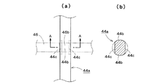
次に、図3に示すローラ回転規制機構におけるロック部材46およびプーリ44の軸44aの構成の詳細について図4および図5を用いて説明する。ここで、図4(a)は、プーリ44の軸44aがロック部材46の凹部46bに挿入されたときの状態を示す図であり、(b)は、(a)に示す状態からプーリ44の軸44aを紙葉類の投入方向(図4における時計回りの方向)に回転させたときの状態を示す図であり、(c)は、(b)に示す状態からプーリ44の軸44aを紙葉類の投入方向に更に回転させたときの状態を示す図である。また、図5は、図4に示すローラ回転規制機構におけるプーリ44の軸44aの構成の詳細を示す構成図であって、図5(a)は、プーリ44の軸44aを上方から見たときの上面図であり、図5(b)は、図5(a)に示すプーリ44の軸44aのA−A矢視断面図である。なお、図5(a)において、参考のためロック部材46を二点鎖線で示している。
Next, details of the configuration of the
図4および図5、とりわけ図5(b)に示すように、プーリ44の軸44aは、ロック部材46の凹部46bに挿入されたときのこの凹部46bに接触する箇所において軸44aの周方向に沿って部分的に平面形状となっている。具体的には、図5(a)(b)に示すように、プーリ44の軸44aには、当該軸44aの中心に対して対称の位置に設けられる一対の平面形状部分44cと、図5(b)に示すような軸44aの断面において一対の平面形状部分44cの間にそれぞれ設けられる一対の周形状部分44bとが設けられている。
As shown in FIGS. 4 and 5, especially FIG. 5B, the
また、図4に示すように、ロック部材46の凹部46bは、プーリ44の軸44aが挿入された際にこの軸44aと略平行に延びる互いに対向する第1の側面部分46cおよび第2の側面部分46e、ならびに底面部分46dを有している。ここで、図4に示すように、第1の側面部分46cおよび底面部分46dは略平面形状となっており、これらの第1の側面部分46cおよび底面部分46dはほぼ直交している。第1の側面部分46cの高さは、軸44aの直径と略同一の大きさとなっており、一方、底面部分46dの幅の大きさは、軸44aの直径よりもわずかに小さくなっている。
Further, as shown in FIG. 4, the
また、第2の側面部分46eは、凹部46bの開口部分に向かって、すなわち上方に向かって広がるようなテーパ形状となっている。より具体的には、第2の側面部分46eには、底面部分46dとほぼ直交するような平面形状部分と、第1の側面部分46cから遠ざかるようこの平面形状部分の途中箇所から傾斜した傾斜部分とが設けられている。第2の側面部分46eの高さは、軸44aの直径よりも小さくなっている。
The second
そして、図4(a)に示すような、プーリ44の軸44aがロック部材46の凹部46bに挿入されたときの状態において、プーリ44の軸44aを紙葉類の投出方向、すなわち図4(a)の矢印Pの方向に回転させた場合には、プーリ44の軸44aに設けられた平面形状部分44cがロック部材46の凹部46bの第1の側面部分46cに当接することにより、このプーリ44の軸44aの回転が規制され、軸44aは図4(a)に示すような状態からこれ以上回転しなくなる。
4A, when the
一方、図4(a)に示すような、プーリ44の軸44aがロック部材46の凹部46bに挿入されたときの状態において、プーリ44の軸44aを紙葉類の投入方向、すなわち図4(a)の矢印Qの方向に回転させた場合には、このプーリ44の軸44aに設けられた平面形状部分44cがロック部材46の凹部46bの第2の側面部分46eに当接する。ここで、第2の側面部分46eは、凹部46bの開口部分に向かって、すなわち上方に向かって広がるようなテーパ形状となっているので、軸44aの平面形状部分44cが凹部46bの第2の側面部分46eに当接した場合であっても、この軸44aの回転が凹部46bにより規制されることはなく、軸44aの回転が許容されることとなる。このため、プーリ44の軸44aは図4(a)に示す状態から矢印Qの方向に回転し、図4(b)に示すような状態となり、図4(b)に示すような状態から軸44aが更に図4(b)の時計回りに回転すると図4(c)に示すような状態となる。このようにして、プーリ44の軸44aを紙葉類の投入方向、すなわち図4(a)の矢印Qの方向に回転させた場合には、この軸44aの回転はロック部材46の凹部46bにより規制されることはなく、軸44aの回転が許容される。
On the other hand, in the state where the
このようにして、ロック部材46は、プーリ44の軸44aが凹部46bに挿入されたときにこのプーリ44の軸44aを紙葉類の投入方向には回転させるが紙葉類の投出方向には回転させないようになっている。
Thus, the
上述のように、ローラ回転規制機構は、紙葉類収納カセット10の循環ベルト40、プーリ42、44、ロック部材46、カム部材50、ピニオン部材52等から構成されている。
As described above, the roller rotation restricting mechanism includes the circulation belt 40, the
次に、このような構成からなる紙葉類収納カセット10の動作について以下に説明する。具体的には、紙葉類収納カセット10を紙葉類処理装置1に装着したときの状態における動作、および紙葉類収納カセット10を紙葉類処理装置1から取り外したときの状態における動作についてそれぞれ説明する。
Next, the operation of the paper
まず、紙葉類収納カセット10を紙葉類処理装置1に装着したときの状態における動作について説明する。
First, an operation in a state when the paper
紙葉類を筐体12の外部から内部に投入する際に、まず、ステージ駆動機構(図示せず)によりステージ30を下降させる。このことにより、ステージ30の上方に紙葉類の収納スペースが設けられることとなる。
When a paper sheet is put into the
その後、投出入口16により紙葉類が1枚ずつ筐体12の内部に投入されると、この紙葉類は紙葉類搬送路18を経てフィードローラ20とゲートローラ22との間のニップ部に送られ、このニップ部に送られた紙葉類はフィードローラ20によりステージ30上に送られる。この際に、フィードローラ20からステージ30に送られる紙葉類は札叩き用羽根車(図示せず)により叩かれることとなる。このため、紙葉類を迅速にステージ30上に落下させることができるとともに、ステージ30上で紙葉類が縦向きになることはなく横向きの積層状態で集積されることとなる。また、フィードローラ20とゲートローラ22との間のニップ部に送られた紙葉類は、コシ付け部材(図示せず)により波形状に変形させられる。このことにより、紙葉類にコシを付けることができる。
Thereafter, when the sheets are fed into the
一方、紙葉類を筐体12の内部から外部に投出する際には、まず、ステージ駆動機構(図示せず)によりステージ30を上昇させる。このことにより、ステージ30上に集積された紙葉類を収納繰出機構のキッカローラ24に当接させることができる。また、ステージ30を上昇させると、札叩き用羽根車(図示せず)およびコシ付け部材(図示せず)は収納繰出機構から退避し、紙葉類の投出が行われる間に紙葉類がこれらの札叩き用羽根車およびコシ付け部材に当接することはなくなる。
On the other hand, when paper sheets are thrown from the inside of the
そして、ステージ30が上昇することによりこのステージ30上に集積された紙葉類がキッカローラ24に当接した後、キッカローラ24により、ステージ30に集積された紙葉類のうち最も上方にある紙葉類をフィードローラ20とゲートローラ22との間のニップ部に蹴り出す。ニップ部に送られた紙葉類は、フィードローラ20により紙葉類搬送路18に送られ、この紙葉類は最終的には投出入口16まで搬送されることとなる。このことにより、紙葉類収納カセット10の筐体12の外部へ紙葉類が投出される。
Then, after the
なお、上述のような、筐体12の外部から内部に紙葉類を投入する場合や、筐体12の内部から外部に紙葉類を投出する場合において、紙葉類収納カセット10が紙葉類処理装置1に装着されているので、紙葉類収納カセット10に設けられたピニオン部材52および紙葉類処理装置1に設けられたラック部材60は図3(c)に示すような位置関係となる。このため、プーリ44の軸44aはロック部材46の凹部46bから完全に外れた位置にあり、この軸44aは図3の時計回りおよび反時計回りの両方向に自在に回転させることができるようになる。このため、プーリ44に張架された循環ベルト40も自在に循環移動させることができるようになり、プーリ42も図2の時計回りおよび反時計回りの両方向に自在に回転させることができるようになるので、フィードローラ20を紙葉類の投入方向および投出方向の両方向に回転させることができるようになる。
Note that the paper
一方、紙葉類収納カセット10の紙葉類収納部に収納された紙葉類を回収する際に、この紙葉類収納カセット10を紙葉類処理装置1から取り外した場合には、紙葉類収納カセット10に設けられたピニオン部材52および紙葉類処理装置1に設けられたラック部材60は図3(a)に示すような位置関係となる。この場合、ロック部材46はバネ56により上方向の力が加えられ、このロック部材46にはバネ56による引っ張り力に抗する力は加えられることがないので、ロック部材46はバネ56により上方向に引っ張られ、このロック部材46の凹部46bにプーリ44の軸44aが挿入されることとなる。
On the other hand, when the paper sheets stored in the paper sheet storage section of the paper
ロック部材46の凹部46bにプーリ44の軸44aが挿入された場合、前述のように、このプーリ44の軸44aは紙葉類の投出方向、すなわち図4(a)の矢印Pの方向には回転させることができなくなる。このため、フィードローラ20を紙葉類の投出方向に回転させることができなくなる。一方、ロック部材46の凹部46bにプーリ44の軸44aが挿入された場合であって、このプーリ44の軸44aは紙葉類の投入方向、すなわち図4(a)の矢印Qの方向には回転させることができる。このため、フィードローラ20を紙葉類の投入方向に回転させることができる。
When the
ここで、前述のような筐体12の外部から内部に紙葉類を投入する際に、この紙葉類がフィードローラ20において詰まった場合であっても(すなわち、フィードローラ20において紙葉類にジャムが発生した場合であっても)、紙葉類収納カセット10を紙葉類処理装置1から取り外した後、この紙葉類収納カセット10の扉を開け、紙葉類収納カセット10の筐体12の内部から、フィードローラ20で詰まった紙葉類を手で引っ張ることにより、このフィードローラ20が紙葉類の投入方向に回転し、紙葉類の詰まりを解消することができる。
Here, even when the paper sheets are jammed in the
そして、図3(a)に示すような、紙葉類収納カセット10が紙葉類処理装置1から取り外されたような状態から、紙葉類収納カセット10を紙葉類処理装置1に装着させはじめると、図3(b)に示すように紙葉類収納カセット10のピニオン部材52が紙葉類処理装置1のラック部材60に噛み合い、このピニオン部材52が回転することにより、バネ56による上方向の力に抗してロック部材46がカム部材50によって下方に引っ張られることとなる。そして、図3(c)に示すように紙葉類収納カセット10を紙葉類処理装置1に完全に装着させると、カム部材50によりロック部材46は大きく下方に引っ張られた状態となり、このロック部材46の凹部46bからプーリ44の軸44aが完全に外れることとなる。
Then, the paper
以上のように本実施の形態の紙葉類収納カセット10およびこの紙葉類収納カセット10を備えた紙葉類処理装置1によれば、紙葉類収納カセット10の循環ベルト40、プーリ42、44、ロック部材46、カム部材50、ピニオン部材52等から構成されるローラ回転規制機構は、紙葉類収納カセット10が紙葉類処理装置1に装着されたときにはフィードローラ20を紙葉類の投入方向および投出方向の両方向に回転させ、一方、紙葉類収納カセット10が紙葉類処理装置1から取り外されたときにはフィードローラ20を紙葉類の投入方向のみに回転させるようフィードローラ20の回転を規制する。このため、紙葉類収納カセット10を紙葉類処理装置1から取り外したときにフィードローラ20を紙葉類の投出方向に回転させることができなくなるため紙葉類収納部に収納された紙葉類が例えば盗難者等により抜き取られることを防止することができる。また、フィードローラ20が設けられた箇所において紙葉類の詰まりが発生した場合でも、紙葉類収納カセット10を紙葉類処理装置1から取り外した後、フィードローラ20を紙葉類の投入方向に例えば手動で回転させることによりこのような紙葉類の詰まりを解消することができる。
As described above, according to the paper
また、ローラ回転規制機構は、フィードローラ20と同期して回転するプーリ44の軸44aと、プーリ44の軸44aの近傍において移動自在に設けられたロック部材46とを有し、紙葉類収納カセット10が紙葉類処理装置1に収容されたときにはロック部材46はプーリ44の軸44aから離間し、紙葉類収納カセット10が紙葉類処理装置1から取り外されたときにはロック部材46はプーリ44の軸44aに係合するようになっている。また、ロック部材46は、プーリ44の軸44aが係合されたときにこのプーリ44の軸44aを紙葉類の投入方向には回転させるが紙葉類の投出方向には回転させないような形状となっている。このような紙葉類収納カセット10によれば、収納繰出機構のフィードローラ20の回転を規制するローラ回転規制機構の構成をシンプルなものとすることができる。
The roller rotation restricting mechanism includes a
なお、本発明による紙葉類収納カセットおよび紙葉類処理装置は、上記の態様に限定されるものではなく、様々の変更を加えることができる。例えば、収納繰出機構のフィードローラの回転を規制するローラ回転規制機構としては、図2乃至図5に示すような循環ベルト40、プーリ42、44、ロック部材46、カム部材50、ピニオン部材52等から構成されるものに限定されることはない。収納繰出機構のフィードローラの回転を規制するローラ回転規制機構として、紙葉類収納カセットが紙葉類処理装置に装着されたときにはフィードローラを紙葉類の投入方向および投出方向の両方向に回転させ、紙葉類収納カセットが紙葉類処理装置から取り外されたときにはフィードローラを紙葉類の投入方向のみに回転させるようフィードローラの回転を規制するものであれば、他の構成のものを用いることもできる。
In addition, the paper sheet storage cassette and the paper sheet processing apparatus according to the present invention are not limited to the above-described embodiments, and various modifications can be made. For example, as a roller rotation restricting mechanism for restricting the rotation of the feed roller of the storing and feeding mechanism, a circulating belt 40, pulleys 42 and 44, a
1 紙葉類処理装置
2 紙葉類投入部
3 紙葉類投出部
4 搬送部
5 識別部
6 筐体
10 紙葉類収納カセット
12 筐体
14 把持部
16 投出入口
18 紙葉類搬送路
20 フィードローラ
20a 軸
22 ゲートローラ
22a 軸
24 キッカローラ
24a 軸
25、26、27 案内ローラ
30 ステージ
31 案内部材
32 案内部材
40 循環ベルト
42 プーリ
44 プーリ
44a 軸
44b 周形状部分
44c 平面形状部分
46 ロック部材
46a 軸
46b 凹部
46c 第1の側面部分
46d 底面部分
46e 第2の側面部分
48 ピン
50 カム部材
50a 軸
50b 開口部
52 ピニオン部材
52a 軸
52b 櫛歯部分
54 固定部材
56 バネ
60 ラック部材
60a 櫛歯部分
DESCRIPTION OF SYMBOLS 1 Paper
Claims (7)
筐体と、
前記筐体の外部から内部への紙葉類の投入および前記筐体の内部から外部への紙葉類の投出を行うための投出入口と、
前記筐体の内部に設けられ、前記投出入口により前記筐体の外部から内部に投入された紙葉類が収納される紙葉類収納部と、
前記筐体の内部に設けられ、前記投出入口により前記筐体の外部から内部に投入された紙葉類を前記紙葉類収納部に送るとともに前記紙葉類収納部に収納された紙葉類を前記投出入口に繰り出すローラを有する収納繰出機構と、
前記収納繰出機構のローラの回転を規制するローラ回転規制機構であって、前記紙葉類収納カセットが前記紙葉類処理装置に装着されたときには前記ローラを紙葉類の投入方向および投出方向の両方向に回転させ、前記紙葉類収納カセットが前記紙葉類処理装置から取り外されたときには前記ローラを紙葉類の投入方向のみに回転させるよう前記ローラの回転を規制するようなローラ回転規制機構と、
を備えたことを特徴とする紙葉類収納カセット。 A paper sheet storage cassette that is detachably stored in a paper sheet processing apparatus for processing paper sheets,
A housing,
An outlet for inputting paper sheets from the outside to the inside of the casing and discharging paper sheets from the inside of the casing to the outside; and
A paper sheet storage unit that is provided inside the housing and stores paper sheets that are thrown into the housing from the outside through the outlet;
Paper sheets that are provided inside the housing and that are fed into the housing from the outside through the outlet port are sent to the paper sheet storage unit and are stored in the paper sheet storage unit. A storage and feeding mechanism having a roller that feeds the outlet to the outlet;
A roller rotation restricting mechanism for restricting the rotation of the rollers of the storage and feeding mechanism, wherein when the paper sheet storage cassette is mounted on the paper sheet processing apparatus, the rollers are moved in and out of the paper sheets. The roller rotation regulation is such that when the paper sheet storage cassette is removed from the paper sheet processing apparatus, the rotation of the roller is restricted so that the roller is rotated only in the paper sheet loading direction. Mechanism,
A paper sheet storage cassette characterized by comprising:
前記紙葉類収納カセットが前記紙葉類処理装置に収容されたときには前記ロック部材は前記軸から離間し、前記紙葉類収納カセットが前記紙葉類処理装置から取り外されたときには前記ロック部材は前記軸に係合し、前記ロック部材は、前記軸が係合されたときにこの軸を紙葉類の投入方向には回転させるが紙葉類の投出方向には回転させないような形状となっていることを特徴とする請求項1記載の紙葉類収納カセット。 The roller rotation restricting mechanism includes a shaft that rotates in synchronization with the roller of the storage and feeding mechanism, and a lock member that is movably provided in the vicinity of the shaft.
When the paper sheet storage cassette is stored in the paper sheet processing apparatus, the lock member is separated from the shaft, and when the paper sheet storage cassette is removed from the paper sheet processing apparatus, the lock member is The lock member is engaged with the shaft, and the lock member has such a shape that, when the shaft is engaged, the shaft is rotated in the paper sheet feeding direction but is not rotated in the paper sheet ejection direction. The paper sheet storage cassette according to claim 1, wherein the paper sheet storage cassette is formed.
前記ピニオン部材は前記ローラ回転規制機構のロック部材と接続されており、前記ピニオン部材が前記ラック部材と噛み合って回転することにより前記ロック部材が移動するようになっていることを特徴とする請求項2記載の紙葉類収納カセット。 The paper sheet storage cassette is provided with a pinion member that meshes with a rack member provided in the paper sheet processing apparatus when the paper sheet storage cassette is stored in the paper sheet processing apparatus. And
The pinion member is connected to a lock member of the roller rotation restricting mechanism, and the lock member moves when the pinion member meshes with the rack member and rotates. 2. The paper sheet storage cassette according to 2.
請求項1乃至6のいずれか一項に記載の紙葉類収納カセットを備えたことを特徴とする紙葉類処理装置。 A paper sheet processing apparatus for storing and dispensing paper sheets,
A paper sheet processing apparatus comprising the paper sheet storage cassette according to any one of claims 1 to 6.
Priority Applications (1)
| Application Number | Priority Date | Filing Date | Title |
|---|---|---|---|
| JP2008226262A JP5456285B2 (en) | 2008-09-03 | 2008-09-03 | Paper sheet storage cassette and paper sheet processing apparatus |
Applications Claiming Priority (1)
| Application Number | Priority Date | Filing Date | Title |
|---|---|---|---|
| JP2008226262A JP5456285B2 (en) | 2008-09-03 | 2008-09-03 | Paper sheet storage cassette and paper sheet processing apparatus |
Publications (2)
| Publication Number | Publication Date |
|---|---|
| JP2010061386A true JP2010061386A (en) | 2010-03-18 |
| JP5456285B2 JP5456285B2 (en) | 2014-03-26 |
Family
ID=42188122
Family Applications (1)
| Application Number | Title | Priority Date | Filing Date |
|---|---|---|---|
| JP2008226262A Active JP5456285B2 (en) | 2008-09-03 | 2008-09-03 | Paper sheet storage cassette and paper sheet processing apparatus |
Country Status (1)
| Country | Link |
|---|---|
| JP (1) | JP5456285B2 (en) |
Cited By (3)
| Publication number | Priority date | Publication date | Assignee | Title |
|---|---|---|---|---|
| KR101468290B1 (en) * | 2013-03-05 | 2014-12-03 | 주식회사 엘지씨엔에스 | Medium cassette, medium process apparatus, and financial device |
| JP2016143390A (en) * | 2015-02-05 | 2016-08-08 | 沖電気工業株式会社 | Medium storage and medium transaction device |
| CN110562773A (en) * | 2019-09-19 | 2019-12-13 | 中北大学 | Paper archives data acquisition device |
Citations (2)
| Publication number | Priority date | Publication date | Assignee | Title |
|---|---|---|---|---|
| JPS60187978U (en) * | 1984-05-23 | 1985-12-12 | オムロン株式会社 | Banknote storage device |
| JPS6453941A (en) * | 1987-08-25 | 1989-03-01 | Nec Corp | Housing device for sheet |
-
2008
- 2008-09-03 JP JP2008226262A patent/JP5456285B2/en active Active
Patent Citations (2)
| Publication number | Priority date | Publication date | Assignee | Title |
|---|---|---|---|---|
| JPS60187978U (en) * | 1984-05-23 | 1985-12-12 | オムロン株式会社 | Banknote storage device |
| JPS6453941A (en) * | 1987-08-25 | 1989-03-01 | Nec Corp | Housing device for sheet |
Cited By (4)
| Publication number | Priority date | Publication date | Assignee | Title |
|---|---|---|---|---|
| KR101468290B1 (en) * | 2013-03-05 | 2014-12-03 | 주식회사 엘지씨엔에스 | Medium cassette, medium process apparatus, and financial device |
| JP2016143390A (en) * | 2015-02-05 | 2016-08-08 | 沖電気工業株式会社 | Medium storage and medium transaction device |
| CN110562773A (en) * | 2019-09-19 | 2019-12-13 | 中北大学 | Paper archives data acquisition device |
| CN110562773B (en) * | 2019-09-19 | 2024-05-24 | 中北大学 | Paper archives data acquisition device |
Also Published As
| Publication number | Publication date |
|---|---|
| JP5456285B2 (en) | 2014-03-26 |
Similar Documents
| Publication | Publication Date | Title |
|---|---|---|
| KR101240055B1 (en) | Automatic cash transaction apparatus | |
| JP2007290850A (en) | Paper sheet accumulation and feeding device | |
| JP4381960B2 (en) | Paper feeding device and image forming apparatus having the same | |
| JP5014419B2 (en) | Coin dispensing device and coin processor | |
| JP5456285B2 (en) | Paper sheet storage cassette and paper sheet processing apparatus | |
| WO2009095995A1 (en) | Coin delivery machine | |
| CN1881266A (en) | Bill handling device | |
| JP2006350836A (en) | Bank bill processor | |
| US9965916B2 (en) | Medium bundle storage device and medium processing device | |
| JP5493247B2 (en) | Shredding equipment | |
| JP5144764B2 (en) | Paper sheet storage cassette | |
| US11900752B2 (en) | Medium processing device and medium transaction device | |
| US20190206197A1 (en) | Protector, medium storage device, and medium processing device | |
| KR102148924B1 (en) | Automated teller machine with a structure capable of maintenance easily | |
| JP2010113533A (en) | Coin processing unit | |
| JP5602350B2 (en) | Paper sheet storage cassette | |
| JP2010280493A (en) | Paper sheet processing device | |
| JP7427117B2 (en) | Paper sheet conveyance device and paper sheet handling device | |
| US9815302B2 (en) | Medium transporting apparatus | |
| JP5105416B2 (en) | Banknote storage device | |
| JP7205177B2 (en) | Coin handling equipment, automatic transaction equipment and coin storage | |
| JP5231630B2 (en) | Coin feeder | |
| JP4287483B2 (en) | Paper processing apparatus and image forming system | |
| JP2007087403A (en) | Bank bill storage/discharge cabinet | |
| JP2005174072A (en) | Coin processing device |
Legal Events
| Date | Code | Title | Description |
|---|---|---|---|
| A621 | Written request for application examination |
Free format text: JAPANESE INTERMEDIATE CODE: A621 Effective date: 20110802 |
|
| A977 | Report on retrieval |
Free format text: JAPANESE INTERMEDIATE CODE: A971007 Effective date: 20130218 |
|
| A131 | Notification of reasons for refusal |
Free format text: JAPANESE INTERMEDIATE CODE: A131 Effective date: 20130329 |
|
| A521 | Written amendment |
Free format text: JAPANESE INTERMEDIATE CODE: A523 Effective date: 20130528 |
|
| TRDD | Decision of grant or rejection written | ||
| A01 | Written decision to grant a patent or to grant a registration (utility model) |
Free format text: JAPANESE INTERMEDIATE CODE: A01 Effective date: 20131210 |
|
| A61 | First payment of annual fees (during grant procedure) |
Free format text: JAPANESE INTERMEDIATE CODE: A61 Effective date: 20140108 |
|
| R150 | Certificate of patent or registration of utility model |
Ref document number: 5456285 Country of ref document: JP Free format text: JAPANESE INTERMEDIATE CODE: R150 Free format text: JAPANESE INTERMEDIATE CODE: R150 |