JP2010060726A - Image forming apparatus - Google Patents
Image forming apparatus Download PDFInfo
- Publication number
- JP2010060726A JP2010060726A JP2008225043A JP2008225043A JP2010060726A JP 2010060726 A JP2010060726 A JP 2010060726A JP 2008225043 A JP2008225043 A JP 2008225043A JP 2008225043 A JP2008225043 A JP 2008225043A JP 2010060726 A JP2010060726 A JP 2010060726A
- Authority
- JP
- Japan
- Prior art keywords
- main body
- transfer unit
- apparatus main
- intermediate transfer
- holding member
- Prior art date
- Legal status (The legal status is an assumption and is not a legal conclusion. Google has not performed a legal analysis and makes no representation as to the accuracy of the status listed.)
- Granted
Links
Images


Landscapes
- Electrophotography Configuration And Component (AREA)
Abstract
Description
本発明は、シート等の記録材上に画像を形成する機能を備えた、例えば、複写機、プリンタなどの画像形成装置に関するものである。 The present invention relates to an image forming apparatus such as a copying machine or a printer having a function of forming an image on a recording material such as a sheet.
従来、レーザビームプリンタ等の画像形成装置においては、次のようなものが主流となっている。それは、レーザ光等によって感光ドラムに描かれた潜像を現像せしめる現像装置と、現像されたトナー像を記録材に転写せしめる転写手段と、転写されたトナー像をシート材上に定着せしめる定着器とを備えたものである。 Conventionally, image forming apparatuses such as laser beam printers are mainly used as follows. A developing device that develops a latent image drawn on a photosensitive drum by a laser beam or the like, a transfer unit that transfers the developed toner image onto a recording material, and a fixing device that fixes the transferred toner image on a sheet material It is equipped with.
そして、プロセスカートリッジとして、帯電手段、現像手段、感光体等を一体的にカートリッジ化している。このカートリッジは、画像形成装置本体に対して着脱可能で、ユーザ交換が可能であり、装置本体のメンテナンスを容易にしている。 As a process cartridge, a charging unit, a developing unit, a photoconductor and the like are integrally formed into a cartridge. This cartridge is detachable from the main body of the image forming apparatus and can be replaced by the user, facilitating maintenance of the main body of the apparatus.
プロセスカートリッジの着脱構成に関しては、例えば特許文献1に示すように、中間転写体ユニット(転写ユニット)を引出し構成とし、プロセスカートリッジごと引出して、プロセスカートリッジを着脱する方式がある。また、本体上部ユニットとして、本体上部ユニットを開くことで、プロセスカートリッジを交換する方式もある。
With respect to the process cartridge mounting / removal configuration, for example, as shown in
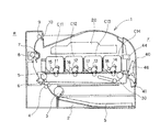
図12は、その代表例としての従来のレーザビームプリンタ101が示される。以下、このレーザビームプリンタ101の全体的構成及び機能について説明する。
FIG. 12 shows a conventional
給送トレイ102内に積載収納された記録材Sは、図中時計方向に回転する給送ローラ103により給送され、搬送ローラ104に送られ、ベルト内ローラ105と転写ローラ106のニップ部へ送られる。
The recording material S stacked and stored in the
感光ドラム111,112,113,114は図中反時計方向に回転しており、その外周面には、レーザスキャナ120からのレーザ光により静電潜像が順次形成される。続いて、その静電潜像が現像ローラ115,116,117,118で現像され、トナー像が感光ドラム111,112,113,114の外周面に形成される。
The
感光ドラム111,112,113,114に形成されたトナー像は、中間転写ベルト130に転写される。カラー画像を形成する場合は、感光ドラム111,112,113,114にイエロー,マゼンダ,シアン,ブラックの各色が現像され、それぞれに形成されたトナー像が、中間転写ベルト130に転写される。
The toner images formed on the
次に、中間転写ベルト130に形成されたトナー像は、ベルト内ローラ105と転写ローラ106のニップ部に送られた記録材Sに転写される。
Next, the toner image formed on the
さらに、トナー像が転写された記録材Sは、定着フィルム107と加圧ローラ108のニップ部へ送られ、ここで加熱加圧されてトナー像が記録材Sに定着される。
Further, the recording material S to which the toner image has been transferred is sent to the nip portion between the
トナー像が定着された記録材Sは、排出ローラ109と排出コロ110により排出される。
The recording material S on which the toner image is fixed is discharged by a
そして、感光ドラム111,112,113,114は、現像ローラ115,116,117,118等と一体となったプロセスカートリッジC111,C112,C113,
C114として、画像形成装置本体に対して着脱可能に設けられている。
The
C114 is provided so as to be detachable from the main body of the image forming apparatus.
レーザスキャナ120等は、本体上部ユニット140に設けられており、本体上部ユニット140は、支点141を中心に回動可能に、画像形成装置本体に設けられている。そして、プロセスカートリッジC111,C112,C113,C114の着脱は、本体上部ユニット140を開いた状態で可能である。
しかしながら、上記従来例では、以下のような問題点が懸念されていた。 However, in the above conventional example, there are concerns about the following problems.
本体上部ユニットを開いた状態でプロセスカートリッジを交換する方式では、画像形成装置本体を大幅にコストアップさせ、また、画像形成装置本体の小型化を妨げることになってしまうことが懸念されていた。これは、本体上部ユニットと画像形成装置本体との締結構造が複雑になったり、本体フレームが上下で分断されるため、本体フレームの強度が不足し、補強のためのステーを増加させる必要が生じたりするためである。 In the system in which the process cartridge is replaced with the main unit upper unit opened, there has been a concern that the cost of the image forming apparatus main body will be greatly increased and that the downsizing of the image forming apparatus main body will be hindered. This is because the fastening structure between the upper unit of the main body and the main body of the image forming apparatus is complicated, or the main body frame is divided into upper and lower parts, so that the strength of the main body frame is insufficient and it is necessary to increase the stay for reinforcement. This is because
中間転写体ユニットを引出す方式でも同様に、本体フレームの側面にユニット引出しのための大きな穴を開けることになり、本体フレームの強度が懸念される。 Similarly, in the method of pulling out the intermediate transfer member unit, a large hole for pulling out the unit is formed on the side surface of the main body frame, and there is a concern about the strength of the main body frame.
本発明は上記したような事情に鑑みてなされたものであり、本体フレームの強度低下を抑えつつ、プロセスカートリッジ及び転写ユニットの交換を容易にすることを目的とする。 The present invention has been made in view of the above-described circumstances, and an object thereof is to facilitate replacement of a process cartridge and a transfer unit while suppressing a decrease in strength of a main body frame.
上記目的を達成するために本発明にあっては、
像担持体と前記像担持体に作用するプロセス手段とをそれぞれ有する複数のプロセスカートリッジと、
装置本体に対して着脱可能に設けられた転写ユニットであって、前記像担持体に形成された現像剤像を転写するために、前記像担持体に接触して前記像担持体との間でニップ部を形成する転写部材を有する転写ユニットと、
を備えた画像形成装置において、
一方向に並列配置されるように複数の前記プロセスカートリッジをそれぞれ着脱可能に保持する移動部材であって、
装置本体内では複数の前記像担持体が前記転写部材と前記ニップ部を形成するニップ部形成位置に位置し、前記ニップ部形成位置から前記一方向に沿うように移動することで装置本体に対して着脱可能に設けられた移動部材と、
前記転写ユニットが装置本体内の正規位置に装着された際に前記転写ユニットが前記正規位置から移動してしまうことを規制する規制位置、及び、前記転写ユニットの位置を規制しない規制解除位置の間を移動可能な規制部材と、
前記規制部材を移動動作させる操作部材と、
を備えることを特徴とする。
In order to achieve the above object, the present invention provides:
A plurality of process cartridges each having an image carrier and process means acting on the image carrier;
A transfer unit detachably attached to the apparatus main body, in order to transfer the developer image formed on the image carrier, between the image carrier and the image carrier A transfer unit having a transfer member forming a nip portion;
In an image forming apparatus comprising:
A moving member that detachably holds a plurality of the process cartridges so as to be arranged in parallel in one direction,
In the apparatus main body, the plurality of image carriers are positioned at a nip part forming position for forming the nip part with the transfer member, and move from the nip part forming position along the one direction with respect to the apparatus main body. A movable member detachably provided,
Between a restriction position that restricts the transfer unit from moving from the normal position when the transfer unit is mounted at a normal position in the apparatus main body, and a restriction release position that does not restrict the position of the transfer unit. A movable regulating member,
An operating member for moving the regulating member;
It is characterized by providing.
本発明によれば、本体フレームの強度低下を抑えつつ、プロセスカートリッジ及び転写ユニットの交換を容易にすることが可能となる。 According to the present invention, it is possible to easily replace the process cartridge and the transfer unit while suppressing a decrease in strength of the main body frame.
以下に図面を参照して、この発明を実施するための最良の形態を例示的に詳しく説明す
る。ただし、この実施の形態に記載されている構成部品の寸法、材質、形状それらの相対配置などは、発明が適用される装置の構成や各種条件により適宜変更されるべきものであり、この発明の範囲を以下の実施の形態に限定する趣旨のものではない。
The best mode for carrying out the present invention will be exemplarily described in detail below with reference to the drawings. However, the dimensions, materials, shapes, and relative arrangements of the components described in this embodiment should be appropriately changed according to the configuration of the apparatus to which the invention is applied and various conditions. It is not intended to limit the scope to the following embodiments.
本発明に係る画像形成装置は、電子写真画像形成方式を用いて記録媒体に画像を形成するものである。そして、画像形成装置の例としては、例えば複写機、プリンタ(例えばレーザビームプリンタ、LEDプリンタ等)、ファクシミリ装置及びワードプロセッサ等が含まれる。また、プロセスカートリッジとは、像担持体と、像担持体に作用する帯電手段、現像手段等のプロセス手段とを一体的にカートリッジ化し、このカートリッジを画像形成装置本体に対して着脱可能とするものである。ここで、プロセスカートリッジは、使用者自身によって装置本体に対する着脱を行うことができるため、装置本体のメンテナンスを容易に行うことが可能となっている。 The image forming apparatus according to the present invention forms an image on a recording medium using an electrophotographic image forming system. Examples of the image forming apparatus include a copying machine, a printer (for example, a laser beam printer, an LED printer, etc.), a facsimile machine, a word processor, and the like. The process cartridge is a cartridge in which an image carrier and process means such as a charging unit and a developing unit that act on the image carrier are integrated into a cartridge, and the cartridge can be attached to and detached from the main body of the image forming apparatus. It is. Here, since the process cartridge can be attached to and detached from the apparatus main body by the user himself, the apparatus main body can be easily maintained.
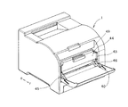
図1は、本発明の実施例1に係る画像形成装置としてレーザビームプリンタ1の概略構成を示す斜視図である。図2は、本実施例のレーザビームプリンタ1の概略構成を示す断面図である。
FIG. 1 is a perspective view illustrating a schematic configuration of a
以下、本実施例のレーザビームプリンタ1の全体的構成及び機能について説明する。ここで、本実施例においては、レーザビームプリンタ1の前面側をFで示し、後面側をRで示すこととする。また、レーザビームプリンタ1の前後方向をF,Rを用いた矢印で示すこととする。また、レーザビームプリンタ1が設置された状態における鉛直方向を上下方向とする。また、レーザビームプリンタ1本体(画像形成装置本体)を、装置本体という。
Hereinafter, the overall configuration and function of the
給送トレイ2内に積載収納された記録材Sは、図中時計方向に回転する給送ローラ3により給送され、搬送ローラ4に送られ、ベルト内ローラ5と転写ローラ6のニップ部へ送られる。
The recording material S stacked and stored in the
像担持体としての感光ドラム11,12,13,14は図中反時計方向に回転しており、その外周面には、レーザスキャナ20からのレーザ光により静電潜像が順次形成される。続いて、その静電潜像が現像ローラ15,16,17,18で現像され、トナー像(現像剤像)が感光ドラム11,12,13,14の外周面に形成される。ここで、少なくとも現像ローラ15,16,17,18は、感光ドラム11,12,13,14にトナー像を形成するプロセス手段に相当する。
The
感光ドラム11,12,13,14に形成されたトナー像は、転写部材としての中間転写ベルト30と感光ドラム11,12,13,14とが接触することでこれらの間にそれぞれ形成されたニップ部で中間転写ベルト30に転写される。カラー画像を形成する場合は、感光ドラム11,12,13,14にイエロー,マゼンダ,シアン,ブラックの各色が現像され、それぞれに形成されたトナー像が、中間転写ベルト30に転写される。
The toner images formed on the
次に、中間転写ベルト30に形成されたトナー像は、ベルト内ローラ5と転写ローラ6のニップ部に送られた記録材Sに転写される。
Next, the toner image formed on the
さらに、トナー像が転写された記録材Sは、定着フィルム7と加圧ローラ8のニップ部へ送られ、ここで加熱加圧されてトナー像が記録材Sに定着される。
Further, the recording material S onto which the toner image has been transferred is sent to the nip portion between the
トナー像が定着された記録材Sは、排出ローラ9と排出コロ10により排出される。
The recording material S on which the toner image is fixed is discharged by a
そして、本実施例の感光ドラム11,12,13,14は、現像ローラ15,16,17,18等と一体となったプロセスカートリッジC11,C12,C13,C14として、装置本体に対して着脱可能に設けられている。また、中間転写ベルト30は、ベルト内ローラ5等とともに、転写ユニットとしての中間転写体ユニット50として、装置本体に対して着脱可能に設けられている。
The photosensitive drums 11, 12, 13, and 14 of this embodiment can be attached to and detached from the apparatus main body as process cartridges C11, C12, C13, and C14 integrated with the developing
次に、プロセスカートリッジの交換方法の概要について説明する。 Next, an outline of a process cartridge replacement method will be described.
図3は、本実施例のレーザビームプリンタ1の概略構成を示す斜視図であり、開閉部材としてのカートリッジドア40が開放された状態を示す図である。図4は、本実施例のレーザビームプリンタ1の概略構成を示す断面図であり、カートリッジドア40が開放された状態を示す図である。図5は、本実施例のプロセスカートリッジの交換について説明するための図であり、移動部材としてのカートリッジトレイ44を引出した状態を示す図である。図6は、本実施例のプロセスカートリッジの交換について説明するための概略図であり、カートリッジドア40とトレイ保持部材42,43の連動機構部分を示す斜視図である。図7は、本実施例のプロセスカートリッジの交換について説明するための概略図であり、カートリッジドア40とトレイ保持部材42の連動機構部分を示す斜視図である。
FIG. 3 is a perspective view showing a schematic configuration of the
本実施例のレーザビームプリンタ1において、プロセスカートリッジの交換は、ユーザビリティ向上のためにプロセスカートリッジをトレイに乗せ、フロントアクセスにより交換する方式である。
In the
すなわち、レーザビームプリンタ1の前面側には、プロセスカートリッジを通過させるための開口部49を開閉するためのカートリッジドア40が設けられている。ここで、プロセスカートリッジC11,C12,C13,C14は、一方向に並列配置された状態でカートリッジトレイ44に保持されている。そして、プロセスカートリッジC11,C12,C13,C14が並列配置される方向(一方向)が、レーザビームプリンタ1の前後(FR)方向となる。
That is, the front side of the
そして、カートリッジドア40が装置本体に対して開状態となり、開口部49が開放されることで、プロセスカートリッジが保持されたカートリッジトレイ44を開口部49から通過させることが可能となる。このように開口部49が開放されることで、装置本体の外部で、カートリッジトレイ44に対してプロセスカートリッジが着脱自在となり、装置本体内からプロセスカートリッジを取り出すことができる。
The
また、カートリッジドア40が装置本体に対して開状態となり、開口部49が開放されることで、プロセスカートリッジが保持されたカートリッジトレイ44を装置本体内へ挿入(移動)させることができる。
Further, the
ここで、本実施例においては、カートリッジドア40はドア下辺側の横軸41を中心に装置本体に対して開閉可能(回動可能)に設けられている。
Here, in this embodiment, the
また、図6に示すように、装置本体の左右のフレーム(筐体、枠体)に対向させて、保持部材として、前後方向を長手方向とする左右一対のトレイ保持部材42,43が配設されている。トレイ保持部材42,43は、カートリッジトレイ(本実施例では枠型部材)44を保持可能に設けられている。すなわち、そして、このトレイ保持部材42,43の間には、カートリッジトレイ44が、前後方向に水平にスライド移動可能に保持されている。そして、カートリッジドア40が開く際の開動作(回動動作)に連動して、トレイ保持部材42,43が図2に示す位置に対して前方向と上方に所定量移動する。
Further, as shown in FIG. 6, a pair of left and right
従来では、プロセスカートリッジを装置本体から引出す前に固定部材や駆動連結、給電部の接点接続を解除する必要があり、解除のための引出し部扉とのリンク機構等複雑な機構部品が必要となる。これに対して、本実施例では、カートリッジドア40が開く際の開動作に連動して、カートリッジトレイ44を保持したトレイ保持部材42,43が移動するので、簡単な構成で、プロセスカートリッジを装置本体から着脱することが可能となる。
Conventionally, before pulling out the process cartridge from the apparatus main body, it is necessary to release the contact connection between the fixing member, the drive connection, and the power feeding unit, and complicated mechanical parts such as a link mechanism with the drawer door for release are required. . On the other hand, in the present embodiment, the
次に、カートリッジドア40とトレイ保持部材42,43の連動機構について図6,7を用いて説明する。
Next, an interlocking mechanism between the
カートリッジドア40の横軸41は、装置本体に対して回転可能に軸受により保持されている(不図示)。カートリッジドア40とトレイ保持部材42,43は、操作部材としてのレバー部材45,46、レバー部材45,46にそれぞれ設けられた横向き軸45a,46a、トレイ保持部材42,43にそれぞれ設けられた縦長孔42a,43aを介して連結されている。これにより、カートリッジドア40が開閉されると、左右のトレイ保持部材42,43には前後方向へ移動動作するための移動力が作用することになる。
The
左右のトレイ保持部材42,43には、それぞれ前後に間隔を開けて2本のピン軸42bが設けられており、2本のピン軸42bは、装置本体の左右フレームに設けられたガイド穴47に係合されている。このピン軸42bとガイド穴47の係合により、トレイ保持部材42,43はそれぞれ左右フレームに支持されている。従って、左右のトレイ保持部材42,43には、それぞれ、ガイド穴47のガイド範囲において左フレーム48と右フレーム(不図示)に対して移動する自由度がある。ここで、トレイ保持部材42,43と、ピン軸42bと、ガイド穴47とは、プロセスカートリッジC11,C12,C13,C14を中間転写ベルト30に対して接離可能(退避可能)とする接離手段に相当する。
The left and right
前述のように、カートリッジドア40が開く際の開動作(回動動作)に連動して、トレイ保持部材42,43が前方向と上方に所定量移動する。このトレイ保持部材42,43の上方への移動により、カートリッジトレイ44も、図2に示す、感光ドラム11,12,13,14と中間転写ベルト30がニップ部を形成するニップ部形成位置から、図4に示すように上方に移動する。このことで、カートリッジトレイ44は、感光ドラム11,12,13,14が中間転写ベルト30より浮き上がった退避位置に位置することとなる。この位置において、カートリッジトレイ44は装置本体より引出し可能の状態となる。
As described above, the
図5では、カートリッジトレイ44が、図4に示す退避位置から引出された状態を示している。カートリッジトレイ44が引出された状態では、プロセスカートリッジC11,C12,C13,C14の上面が開放されることとなる。そして、それぞれのプロセスカートリッジC11,C12,C13,C14が、レーザビームプリンタ1の外部で、上方(図5に示す矢印方向)に取り外し可能になる。ここで、図5に示すカートリッジトレイ44の位置は、図4に示す退避位置から、プロセスカートリッジC11,C12,C13,C14が並列配置されている一方向(前後方向)に沿うように移動した位置(着脱位置)である。
FIG. 5 shows a state where the
また、プロセスカートリッジC11,C12,C13,C14を装置本体に装着する際は、逆の手順となる。 When the process cartridges C11, C12, C13, and C14 are mounted on the apparatus main body, the reverse procedure is performed.
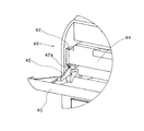
次に、中間転写体ユニット50の交換方法について説明する。図8は、本実施例の中間転写体ユニット50の交換について説明するための図である。
Next, a method for replacing the intermediate
中間転写体ユニット50は、レーザビームプリンタ1の位置決め部51により位置決め
されることで、装置本体内の正規位置に位置している。
The intermediate
中間転写体ユニット50を交換する際は、図5に示す状態のレーザビームプリンタ1から、カートリッジトレイ44を取り出した状態で行う。すなわち、中間転写体ユニット50を交換する際は、まず、カートリッジドア40を開き、図5に示すように、カートリッジトレイ44をレーザビームプリンタ1から引出した状態とする。そして、図5に示す状態のレーザビームプリンタ1から、カートリッジトレイ44を取り出す。その後、中間転写体ユニット50の手前側を持ち上げ(図8参照)、中間転写体ユニット50を位置決め部51から外す(位置決め状態を解除する)ことによりレーザビームプリンタ1の前方に取り出すことができる。
When the intermediate
図9,10は、本実施例の特徴的な構成を示す概略図であり、中間転写体ユニット50とトレイ保持部材43とを示す斜視図である。
9 and 10 are schematic views showing a characteristic configuration of the present embodiment, and are perspective views showing the intermediate
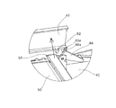
図9に示すように、中間転写体ユニット50は、カートリッジドア40が閉まった状態においては、トレイ保持部材43の凸部52によって、中間転写体ユニット50の位置決め上部53が押さえられた状態となっている。カートリッジドア40が閉まった状態において、トレイ保持部材43は、ニップ部形成位置に位置するカートリッジトレイ44を保持している。ここで、図9,10においては、説明の便宜上、トレイ保持部材43側のみについて示しているが、トレイ保持部材42側の構成もトレイ保持部材43側の構成と同様である。すなわち、前後方向及び上下方向に対して直交する方向(感光ドラムの軸方向)に関して、中間転写体ユニット50の両端にそれぞれ設けられた位置決め上部53が、トレイ保持部材42,43にそれぞれ設けられた凸部に押さえられることとなる。
As shown in FIG. 9, the intermediate
凸部52は、位置決め上部53を押さえる規制位置(図9に示す位置)に位置することで、装置本体内の正規位置に装着された際に中間転写体ユニット50が正規位置から移動してしまうことを規制するものであって、規制部材に相当する。これにより、中間転写体ユニット50が、位置決め部51から外れてしまう(位置決め状態が解除されてしまう)ことを規制することができる。
Since the
したがって、外部からの衝撃や振動により中間転写体ユニット50が装置本体に対して自由に浮いてしまうことを防止することができる。
Therefore, it is possible to prevent the intermediate
また、トレイ保持部材43の凸部52は、カートリッジドア40が開くことで移動して、中間転写体ユニット50の位置決め上部53から外れる(離間する)ことにより、位置決め上部53の位置を規制しない規制解除位置に位置する(図10参照)。これにより、中間転写体ユニット50の交換時に邪魔となることはない。
Further, the
このように、カートリッジドア40の開動作に連動して、中間転写体ユニット50の浮き防止が解除される。このため、カートリッジドア40を開放した後は、カートリッジトレイ44を取り外すという簡単な作業(操作)のみで、中間転写体ユニット50の交換を行うことができる。
Thus, in conjunction with the opening operation of the
次に、交換した中間転写体ユニット50を装着する場合について説明する。
Next, the case where the replaced intermediate
中間転写体ユニット50を交換した後、交換した中間転写体ユニット50を装置本体内に装着し、プロセスカートリッジを保持させたカートリッジトレイ44を図4に示す退避位置まで移動させる。この状態で、カートリッジドア40が閉じられると、レバー部材45,46を介してカートリッジドア40に連結されたトレイ保持部材42,43が、カートリッジドア40の閉動作に連動して移動することとなる。
After replacing the intermediate
これにより、トレイ保持部材42,43に保持されたカートリッジトレイ44がニップ部形成位置に位置することとなる。さらには、トレイ保持部材の凸部が、中間転写体ユニット50の位置決め上部53を押さえる規制位置(図9に示す位置)に位置することとなる。
As a result, the
このように、カートリッジドア40の閉動作に連動して、中間転写体ユニット50の浮き防止が可能となる。したがって、カートリッジドア40の閉動作という簡単な作業(操作)のみで、外部からの衝撃や振動により中間転写体ユニット50が装置本体に対して自由に浮いてしまうことを防止することができる。
In this manner, the intermediate
以上説明したように、本実施例によれば、複数のプロセスカートリッジを着脱可能に保持するカートリッジトレイ44を、複数のプロセスカートリッジが並列配置される方向に移動可能に構成している。このことで、装置本体のフレームの強度低下を抑えつつ、プロセスカートリッジの交換を容易にすることができる。
As described above, according to the present embodiment, the
また、本実施例では、カートリッジドア40を閉めた状態では、装置本体に対し交換可能な中間転写体ユニット50の浮きを防止し、カートリッジドア40が開いた状態においては、中間転写体ユニット50が装置本体に対してフリーとなるように構成されている。これにより、中間転写体ユニット50の交換も容易に行うことが可能となる。
Further, in this embodiment, when the
また、トレイ保持部材42,43がカートリッジドア40の開閉動作に連動して作動して、中間転写体ユニット50の規制及びその解除を行うことができる。これにより、カートリッジドア40の開閉動作という簡単な操作のみで中間転写体ユニット50を交換できる。さらには、カートリッジドア40の閉動作という簡単な操作のみで、外部からの衝撃や振動により中間転写体ユニット50が装置本体に対して浮いてしまうことを防止できる。プロセスカートリッジを交換(着脱)するための開口部49を用いて中間転写体ユニット50を交換できるので、本体フレームの強度を落とすことなく、中間転写体ユニット50の交換を簡単な操作で行うことができる。
Further, the
したがって、安価で簡単な構造、且つ本体フレームの強度を落とすことなくユーザビリティを向上させ、且つ外部からの振動や衝撃に対しても画像形成装置内部での破損を回避することができる。 Therefore, it is possible to improve the usability without lowering the strength of the main body frame with an inexpensive and simple structure, and to avoid damage inside the image forming apparatus against external vibration and impact.
なお、本実施例においては、カートリッジトレイ44をトレイ保持部材42,43に保持させることで、図2に示すニップ部形成位置から図4に示す退避位置に移動させてから、前後方向に沿うように移動可能としているが、これに限るものではない。例えば、カートリッジトレイ44にピン軸が設けられ、ニップ部形成位置から装置本体の外部までピン軸をガイドするガイド穴が装置本体のフレームに設けられるような構成であってもよい。この場合、カートリッジトレイ44がニップ部形成位置から前後方向に沿うように移動するものであるとよい。
In this embodiment, the
また、本実施例では、カートリッジドア40の開閉動作に連動して、規制部材を構成するトレイ保持部材42,43を移動させるものであったが、これに限るものではない。本実施例の構成に対して、カートリッジドア40とレバー部材45,46とが連動しない構成とし、さらに使用者がレバー部材45,46を操作可能に設けてもよい。このような構成により、使用者によるレバー部材45,46の操作に連動して、トレイ保持部材42,43を移動させるものであってもよい。
In the present embodiment, the
また、本実施例では、トレイ保持部材42,43の一部である凸部52が規制部材とし
て中間転写体ユニット50の位置を規制しているが、これに限るものではない。トレイ保持部材42,43とは異なる部材が、レバー部材45,46により移動動作されることにより、中間転写体ユニット50の位置を規制するものであってもよい。
In the present embodiment, the
以下に、本発明の実施例2について説明する。 The second embodiment of the present invention will be described below.
図11は、本実施例の中間転写体ユニット50が、レーザビームプリンタ1の位置決め部51に位置決めされていない状態を示す概略斜視図である。ここで、図11に示すトレイ保持部材43においては、矢印方向に移動する様子を示している。図11において、矢印方向に向かって順に、縦長孔43aは43a1,43a2,43a3の符号で示す位置をとり、これに対応して、凸部52は52a,52b,52cの符号で示す位置をとる。なお、本実施例においては、実施例1に対して異なる構成部分について述べることとし、実施例1と同様の構成部分については、その説明を省略する。
FIG. 11 is a schematic perspective view showing a state where the intermediate
実施例1においては、交換時に、中間転写体ユニット50がレーザビームプリンタ1の位置決め部51(正規位置)に確実に位置決めされていない場合(図11)には、次のようなことが懸念される。すなわち、このような場合に、カートリッジドア40が閉められ、トレイ保持部材42,43が移動してカートリッジトレイ44がニップ部形成位置に移動すると、プロセスカートリッジが中間転写ベルト30に当接する際に破損する可能性がある。
In the first embodiment, when the intermediate
そこで、本実施例では、カートリッジドア40が閉じる際に、規制解除位置から規制位置に移動するトレイ保持部材43の凸部52によって、位置決め部51に向けて押圧される被押圧部54が中間転写体ユニット50に設けられている。
Therefore, in the present embodiment, when the
このような構成により、カートリッジドア40が閉じる際、トレイ保持部材43の凸部52が中間転写体ユニット50の被押圧部54を押し込むことで、中間転写体ユニット50を正規位置、すなわち位置決め部51に押し込むことができる。
With such a configuration, when the
中間転写体ユニット50が正規位置にいるとき、すなわち位置決め部51に確実に位置決めされている場合には、トレイ保持部材43の凸部52が中間転写体ユニット50の被押圧部54に触れないように配置されている。
When the intermediate
このように、本実施例によれば、カートリッジドア40が閉じる際に、正規位置に収まっていない中間転写体ユニット50を正規位置に押し込むことが可能となる。このことにより、中間転写体ユニット50が正規位置に収まっていない状態で、カートリッジトレイ44が装置本体内に入ることによる中間転写ベルト30の破損等を防止することができる。
Thus, according to this embodiment, when the
ここで、中間転写ベルト30がトレイ保持部材42,43により押し込むことができないほど位置決め部51に対して浮いてしまう(ずれてしまう)場合がある。
Here, the
本実施例では、このような場合に、カートリッジトレイ44をレーザビームプリンタ1に装着しようとすると、カートリッジトレイ44が中間転写体ユニット50に当たってしまい、レーザビームプリンタ1本体内に入ることができないように構成されている。
In this embodiment, in such a case, when the
これは、カートリッジトレイ44がトレイ保持部材42,43により退避位置で保持された場合にカートリッジトレイ44が位置する領域に、中間転写体ユニット50の一部が存在するためである。
This is because when the
このため、中間転写体ユニット50が正規位置にないことを、カートリッジトレイ44の装着前に認識することができる。
Therefore, it can be recognized that the intermediate
このように、中間転写体ユニット50を正規位置に押し込むことができない場合は、カートリッジトレイ44が装置本体内に入ることができないように構成されている。このことにより、交換時に、中間転写体ユニット50が正規位置にないことを認識することができるため、カートリッジトレイ44が装置本体内に入ることによる中間転写ベルト30の破損等を防止することができる。
As described above, when the intermediate
1 レーザビームプリンタ
11,12,13,14 感光ドラム
15,16,17,18 現像ローラ
30 中間転写ベルト
44 カートリッジトレイ
45,46 レバー部材
50 中間転写体ユニット
52 凸部
C11,C12,C13,C14 プロセスカートリッジ
DESCRIPTION OF
Claims (5)
装置本体に対して着脱可能に設けられた転写ユニットであって、前記像担持体に形成された現像剤像を転写するために、前記像担持体に接触して前記像担持体との間でニップ部を形成する転写部材を有する転写ユニットと、
を備えた画像形成装置において、
一方向に並列配置されるように複数の前記プロセスカートリッジをそれぞれ着脱可能に保持する移動部材であって、
装置本体内では複数の前記像担持体が前記転写部材と前記ニップ部を形成するニップ部形成位置に位置し、前記ニップ部形成位置から前記一方向に沿うように移動することで装置本体に対して着脱可能に設けられた移動部材と、
前記転写ユニットが装置本体内の正規位置に装着された際に前記転写ユニットが前記正規位置から移動してしまうことを規制する規制位置、及び、前記転写ユニットの位置を規制しない規制解除位置の間を移動可能な規制部材と、
前記規制部材を移動動作させる操作部材と、
を備えることを特徴とする画像形成装置。 A plurality of process cartridges each having an image carrier and process means acting on the image carrier;
A transfer unit detachably attached to the apparatus main body, in order to transfer the developer image formed on the image carrier, between the image carrier and the image carrier A transfer unit having a transfer member forming a nip portion;
In an image forming apparatus comprising:
A moving member that detachably holds a plurality of the process cartridges so as to be arranged in parallel in one direction,
In the apparatus main body, the plurality of image carriers are positioned at a nip part forming position for forming the nip part with the transfer member, and move from the nip part forming position along the one direction with respect to the apparatus main body. A movable member detachably provided,
Between a restriction position that restricts the transfer unit from moving from the normal position when the transfer unit is mounted at a normal position in the apparatus main body, and a restriction release position that does not restrict the position of the transfer unit. A movable regulating member,
An operating member for moving the regulating member;
An image forming apparatus comprising:
前記移動部材は、前記保持部材により保持されて前記ニップ部形成位置から退避した退避位置で、装置本体に対して前記一方向に沿うように移動可能に設けられ、
前記保持部材の一部が前記規制部材として前記転写ユニットの位置を規制するものであって、
前記操作部材は、前記保持部材を移動動作させ、
前記保持部材により保持された前記移動部材が前記ニップ部形成位置に位置した場合、前記保持部材は、前記転写ユニットが前記正規位置から移動してしまうことを規制し、
前記保持部材により保持された前記移動部材が前記退避位置に位置した場合、前記保持部材は、前記転写ユニットの位置を規制しないことを特徴とする請求項1に記載の画像形成装置。 A holding member capable of holding the moving member is movably movable, and the moving member held by the holding member can be retracted from the nip forming position so that the image carrier is brought into contact with and separated from the transfer member. Equipped with possible contact and separation means,
The moving member is provided in a retracted position held by the holding member and retracted from the nip portion forming position so as to be movable along the one direction with respect to the apparatus main body.
A part of the holding member regulates the position of the transfer unit as the regulating member,
The operation member moves the holding member;
When the moving member held by the holding member is located at the nip portion forming position, the holding member restricts the transfer unit from moving from the normal position;
The image forming apparatus according to claim 1, wherein when the moving member held by the holding member is positioned at the retracted position, the holding member does not regulate a position of the transfer unit.
前記操作部材は、前記開閉部材の開閉動作に連動して、前記保持部材を移動動作させるように設けられ、
前記開閉部材の開動作により、前記保持部材により保持された前記移動部材が前記退避位置に位置し、前記保持部材は前記転写ユニットの位置を規制せず、
前記開閉部材の閉動作により、前記保持部材により保持された前記移動部材が前記ニップ部形成位置に位置し、前記保持部材は前記転写ユニットが前記正規位置から移動してしまうことを規制することを特徴とする請求項2に記載の画像形成装置。 An opening / closing member provided so as to be openable / closable with respect to the apparatus main body;
The operation member is provided to move the holding member in conjunction with the opening / closing operation of the opening / closing member,
By the opening operation of the opening and closing member, the moving member held by the holding member is positioned at the retracted position, the holding member does not regulate the position of the transfer unit,
By the closing operation of the opening / closing member, the moving member held by the holding member is positioned at the nip portion forming position, and the holding member restricts the transfer unit from moving from the normal position. The image forming apparatus according to claim 2.
写ユニットを装置本体に装着した際に、前記転写ユニットが前記正規位置に対してずれて装着されている場合であって、前記被押圧部が、前記規制解除位置から前記規制位置に移動する前記規制部材によって押圧されない場合には、前記移動部材が前記保持部材により前記退避位置で保持された場合に前記移動部材が位置する領域に、前記転写ユニットの一部が存在するように構成されていることを特徴とする請求項4に記載の画像形成装置。 When the transfer unit is mounted on the apparatus main body from a state where the moving member and the transfer unit are removed from the apparatus main body, the transfer unit is mounted with a deviation from the normal position. When the pressed member is not pressed by the restriction member that moves from the restriction release position to the restriction position, the movement member is positioned when the movement member is held at the retracted position by the holding member. The image forming apparatus according to claim 4, wherein a part of the transfer unit is present in a region where the image is transferred.
Priority Applications (1)
| Application Number | Priority Date | Filing Date | Title |
|---|---|---|---|
| JP2008225043A JP5171488B2 (en) | 2008-09-02 | 2008-09-02 | Image forming apparatus |
Applications Claiming Priority (1)
| Application Number | Priority Date | Filing Date | Title |
|---|---|---|---|
| JP2008225043A JP5171488B2 (en) | 2008-09-02 | 2008-09-02 | Image forming apparatus |
Publications (3)
| Publication Number | Publication Date |
|---|---|
| JP2010060726A true JP2010060726A (en) | 2010-03-18 |
| JP2010060726A5 JP2010060726A5 (en) | 2011-11-10 |
| JP5171488B2 JP5171488B2 (en) | 2013-03-27 |
Family
ID=42187614
Family Applications (1)
| Application Number | Title | Priority Date | Filing Date |
|---|---|---|---|
| JP2008225043A Active JP5171488B2 (en) | 2008-09-02 | 2008-09-02 | Image forming apparatus |
Country Status (1)
| Country | Link |
|---|---|
| JP (1) | JP5171488B2 (en) |
Cited By (2)
| Publication number | Priority date | Publication date | Assignee | Title |
|---|---|---|---|---|
| JP2012181257A (en) * | 2011-02-28 | 2012-09-20 | Brother Ind Ltd | Image forming device |
| JP2013003519A (en) * | 2011-06-21 | 2013-01-07 | Canon Inc | Image forming apparatus |
Citations (4)
| Publication number | Priority date | Publication date | Assignee | Title |
|---|---|---|---|---|
| JPH11327317A (en) * | 1998-05-15 | 1999-11-26 | Mita Ind Co Ltd | Image forming device |
| JP2007057953A (en) * | 2005-08-25 | 2007-03-08 | Brother Ind Ltd | Image forming apparatus |
| JP2007213033A (en) * | 2006-01-11 | 2007-08-23 | Canon Inc | Electrophotographic image forming apparatus |
| JP2008134317A (en) * | 2006-11-27 | 2008-06-12 | Brother Ind Ltd | Image forming apparatus |
-
2008
- 2008-09-02 JP JP2008225043A patent/JP5171488B2/en active Active
Patent Citations (4)
| Publication number | Priority date | Publication date | Assignee | Title |
|---|---|---|---|---|
| JPH11327317A (en) * | 1998-05-15 | 1999-11-26 | Mita Ind Co Ltd | Image forming device |
| JP2007057953A (en) * | 2005-08-25 | 2007-03-08 | Brother Ind Ltd | Image forming apparatus |
| JP2007213033A (en) * | 2006-01-11 | 2007-08-23 | Canon Inc | Electrophotographic image forming apparatus |
| JP2008134317A (en) * | 2006-11-27 | 2008-06-12 | Brother Ind Ltd | Image forming apparatus |
Cited By (2)
| Publication number | Priority date | Publication date | Assignee | Title |
|---|---|---|---|---|
| JP2012181257A (en) * | 2011-02-28 | 2012-09-20 | Brother Ind Ltd | Image forming device |
| JP2013003519A (en) * | 2011-06-21 | 2013-01-07 | Canon Inc | Image forming apparatus |
Also Published As
| Publication number | Publication date |
|---|---|
| JP5171488B2 (en) | 2013-03-27 |
Similar Documents
| Publication | Publication Date | Title |
|---|---|---|
| KR101721013B1 (en) | Image forming apparatus | |
| KR102333305B1 (en) | Developing cartridge mountable to main assembly of image forming apparatus | |
| US8112014B2 (en) | Color electrophotographic image forming apparatus | |
| JP6041534B2 (en) | Image forming apparatus | |
| JP6990822B2 (en) | Develop equipment, process cartridges and image forming equipment | |
| US7813670B2 (en) | Developing cartridge, process cartridge, and electrophotographic image forming apparatus | |
| US20180120758A1 (en) | Image forming apparatus | |
| JP2006330694A (en) | Electrophotographic image forming apparatus and process cartridge | |
| JP4732005B2 (en) | Image forming apparatus | |
| US20150261178A1 (en) | Image forming apparatus and process cartridge | |
| JP5882609B2 (en) | Image forming apparatus | |
| US8254809B2 (en) | Electrophotographic image forming apparatus | |
| JP2007086392A (en) | Image forming apparatus | |
| US8639162B2 (en) | Color electrophotographic image forming apparatus | |
| JP5171488B2 (en) | Image forming apparatus | |
| JP2017167523A (en) | Image forming apparatus | |
| JP4298669B2 (en) | Image forming apparatus | |
| JP2018049198A (en) | Image forming apparatus and apparatus body | |
| JP4645745B2 (en) | Image forming apparatus | |
| JP2006171534A (en) | Image forming apparatus | |
| US20240027956A1 (en) | Image forming apparatus having improved mountability of a cartridge while conserving space | |
| JP2008026361A (en) | Image forming apparatus | |
| JP2017015865A (en) | Image forming apparatus | |
| JP2023030291A (en) | Image forming apparatus | |
| JP2023023902A (en) | Image forming apparatus |
Legal Events
| Date | Code | Title | Description |
|---|---|---|---|
| A621 | Written request for application examination |
Free format text: JAPANESE INTERMEDIATE CODE: A621 Effective date: 20110901 |
|
| A521 | Written amendment |
Free format text: JAPANESE INTERMEDIATE CODE: A523 Effective date: 20110922 |
|
| TRDD | Decision of grant or rejection written | ||
| A01 | Written decision to grant a patent or to grant a registration (utility model) |
Free format text: JAPANESE INTERMEDIATE CODE: A01 Effective date: 20121127 |
|
| A977 | Report on retrieval |
Free format text: JAPANESE INTERMEDIATE CODE: A971007 Effective date: 20121128 |
|
| A61 | First payment of annual fees (during grant procedure) |
Free format text: JAPANESE INTERMEDIATE CODE: A61 Effective date: 20121225 |
|
| R151 | Written notification of patent or utility model registration |
Ref document number: 5171488 Country of ref document: JP Free format text: JAPANESE INTERMEDIATE CODE: R151 |
|
| FPAY | Renewal fee payment (event date is renewal date of database) |
Free format text: PAYMENT UNTIL: 20160111 Year of fee payment: 3 |