JP2010060523A - Beam position monitor and beam position measuring method of particle beam therapy device - Google Patents
Beam position monitor and beam position measuring method of particle beam therapy device Download PDFInfo
- Publication number
- JP2010060523A JP2010060523A JP2008228925A JP2008228925A JP2010060523A JP 2010060523 A JP2010060523 A JP 2010060523A JP 2008228925 A JP2008228925 A JP 2008228925A JP 2008228925 A JP2008228925 A JP 2008228925A JP 2010060523 A JP2010060523 A JP 2010060523A
- Authority
- JP
- Japan
- Prior art keywords
- irradiation
- signal
- beam position
- particle beam
- digital signal
- Prior art date
- Legal status (The legal status is an assumption and is not a legal conclusion. Google has not performed a legal analysis and makes no representation as to the accuracy of the status listed.)
- Granted
Links
Images


Abstract
Description
本発明は、粒子線治療装置に適用され、粒子線ビームのビーム位置を測定するビーム位置モニタ及び粒子線ビームのビーム位置測定方法に関する。 The present invention relates to a beam position monitor and a beam position measurement method for a particle beam, which are applied to a particle beam therapy system and measure the beam position of a particle beam.
従来、炭素などの重粒子線ビームや陽子線ビームなどの粒子線ビームを被検体の患部に照射し癌細胞を死滅させる粒子線治療装置として、照射部位を仮想的に3次元格子点に切り分けて粒子線ビームを照射することにより正常部位の被爆低減を図りつつ効果的に癌細胞を死滅させるスキャニング照射法が開発されている。 Conventionally, as a particle beam therapy apparatus that irradiates an affected part of a subject with a particle beam such as a heavy particle beam such as carbon or a proton beam, and kills cancer cells, the irradiation site is virtually divided into three-dimensional lattice points. A scanning irradiation method has been developed that effectively kills cancer cells while reducing exposure to normal sites by irradiating a particle beam.
スキャニング照射法の1つとして、スポットスキャニング照射法がある。スポットスキャニング照射法では、ある照射点に照射された線量がその照射点に対する設定値に到達したことを示す線量満了信号が生成されるタイミングで粒子線ビームの照射を一旦停止させる。その後、粒子線ビームの照射位置を次の照射点まで走査するスキャニング電磁石に供給されてスキャニング電磁石を駆動させる励磁電流が一定となったことを示す照射位置設定完了信号が生成されるタイミングで再び粒子線ビームの照射を開始する。この操作を繰り返すことにより患部全域の照射が行われる。 As one of the scanning irradiation methods, there is a spot scanning irradiation method. In the spot scanning irradiation method, irradiation with a particle beam is temporarily stopped at a timing at which a dose expiration signal is generated indicating that a dose irradiated to a certain irradiation point has reached a set value for the irradiation point. After that, the particles are again generated at the timing when the irradiation position setting completion signal is generated, which is supplied to the scanning electromagnet that scans the irradiation position of the particle beam to the next irradiation point and indicates that the excitation current for driving the scanning electromagnet becomes constant. Start irradiation with a line beam. By repeating this operation, irradiation of the entire affected area is performed.
しかしながら、スポットスキャニング照射法では、線量満了信号が生成されても粒子線ビームは直には停止されず、粒子線ビームの照射位置をある照射点から次の照射点まで走査する間に被検体に照射される線量、即ち被検体の正常部位に対する漏れ線量が問題となる。特に各照射点に照射すべきとして設定された線量が小さいときは、漏れ線量の比率(漏れ線量/設定線量)が大きくなる。正常部位に対する漏れ線量の影響を低減するには、ビーム強度を低下させて漏れ線量の比率を相対的に小さくする必要があるが、ビーム強度を低下させることは治療期間の長期化を招いて患者の身体的負担を増大させることになる。 However, in the spot scanning irradiation method, even if a dose expiration signal is generated, the particle beam does not stop immediately, and the particle beam is irradiated on the subject while scanning the irradiation position from one irradiation point to the next irradiation point. The dose to be irradiated, that is, the leak dose to the normal part of the subject becomes a problem. In particular, when the dose set to irradiate each irradiation point is small, the ratio of leaked dose (leakage dose / set dose) increases. To reduce the influence of leakage dose on normal sites, it is necessary to lower the beam intensity to make the ratio of leakage dose relatively small. However, reducing the beam intensity leads to a longer treatment period and the patient. Will increase the physical burden on the body.
スポットスキャニング照射法の問題を解決するため、ラスタースキャニング照射法が注目される(例えば、非特許文献1参照)。ラスタースキャニング照射法では、スポットスキャニング照射法と異なり、照射位置を変えるときも粒子線ビームを停止させない。粒子線ビームが走査されていない状態で照射される照射点を停止照射点と称せば、ラスタースキャニング照射法においては、粒子線ビームの走査途中の照射線量も考慮して各停止照射点に対する照射線量の最適化が行なわれる。但し、照射位置に走査される粒子線ビームのビーム位置はビーム位置モニタにより監視されるため、ビーム位置モニタのビーム位置測定精度は高いものが要求される。 In order to solve the problem of the spot scanning irradiation method, the raster scanning irradiation method is attracting attention (for example, see Non-Patent Document 1). Unlike the spot scanning irradiation method, the raster scanning irradiation method does not stop the particle beam even when the irradiation position is changed. If the irradiation point irradiated with the particle beam beam not scanned is called a stop irradiation point, in the raster scanning irradiation method, the irradiation dose for each stop irradiation point is also taken into consideration in the irradiation dose during the scanning of the particle beam. Optimization is performed. However, since the beam position of the particle beam scanned at the irradiation position is monitored by the beam position monitor, the beam position monitor is required to have high beam position measurement accuracy.
従来、ラスタースキャニング照射で用いられるビーム位置モニタとして、電離箱中の収集電極の電極部分が1軸方向に配列され且つ電気的に接続されない多数の収集電極要素たるストリップを有し、各ストリップに入射した粒子線ビームによる電離作用を利用して電荷を収集電荷として収集し、この収集電荷を用いてビーム位置を算出する信号処理回路を持つビーム位置モニタが知られている(例えば、特許文献1参照)。 Conventionally, as a beam position monitor used in raster scanning irradiation, an electrode portion of a collecting electrode in an ionization chamber has a strip as a number of collecting electrode elements arranged in one axial direction and not electrically connected, and is incident on each strip. There is known a beam position monitor having a signal processing circuit that collects charges as collected charges by using the ionization action by the particle beam, and calculates the beam position using the collected charges (see, for example, Patent Document 1). ).
従来のビーム位置モニタにあっては、収集電極にて収集された収集電荷の電気量が積分器により積算され、積算された収集電荷の電気量を用いてビーム位置が算出される。ビーム位置の特定は、粒子線ビームが入射する収集電極における所謂スポットで収集された収集電荷の電気量を利用して、粒子線ビームの重心位置を演算することにより行なわれるのが一般的である。
ラスタースキャニング照射法では照射位置間を走査するときも粒子線ビームを停止させないため、従来のビーム位置モニタでは粒子線ビームを照射点間で走査している途中で収集される電荷も収集電荷として積算される。そのため、粒子線ビームの走査途中で収集された電荷と走査完了時に収集された電荷とが正確に区別されないことが主因となってビーム位置測定の精度が低下するという問題がある。特に、ある停止照射点から次の停止照射点までの距離が大きいほど、ビーム位置モニタのビーム位置測定精度の低下度合いも大きくなる。 In the raster scanning irradiation method, the particle beam is not stopped even when scanning between irradiation positions, so in the conventional beam position monitor, the charges collected while scanning the particle beam between the irradiation points are also integrated as collected charges. Is done. Therefore, there is a problem that the accuracy of beam position measurement is lowered mainly because the charges collected during the scanning of the particle beam and the charges collected at the completion of scanning are not accurately distinguished. In particular, the greater the distance from one stop irradiation point to the next stop irradiation point, the greater the degree of decrease in beam position measurement accuracy of the beam position monitor.
また、ラスタースキャニング照射法では、照射時間は各停止照射点毎のばらつき即ち収集電荷の電気量のばらつきが大きく、通常の治療計画にあっては2桁程度の違いがあり得る。積分器を用いた従来のビーム位置モニタでは、容量の異なるコンデンサを複数設け、照射時間の長短に応じてこれらコンデンサを適宜切り替えることにより、ビーム位置測定精度を確保することが必要となる。しかしながら、コンデンサを複数設ける構成を採ると、信号処理回路が複雑化して小型化や低コスト化が難しいものとなる。 Further, in the raster scanning irradiation method, the irradiation time has a large variation at each stop irradiation point, that is, a variation in the amount of electricity of the collected charges, and there can be a difference of about two digits in a normal treatment plan. In a conventional beam position monitor using an integrator, it is necessary to provide a plurality of capacitors having different capacities, and to switch the capacitors as appropriate according to the length of irradiation time, thereby ensuring beam position measurement accuracy. However, if a configuration in which a plurality of capacitors are provided is adopted, the signal processing circuit becomes complicated, and it becomes difficult to reduce the size and cost.
本発明は上記問題に鑑みてなされたもので、ラスタースキャニング法にあっても粒子線ビームのビーム位置を精度よく測定し且つビーム位置モニタの小型化或いは低コスト化が図れる粒子線治療装置用のビーム位置モニタ及び粒子線ビームのビーム位置測定方法を提供することを目的とする。 The present invention has been made in view of the above problems, and is intended for a particle beam therapy system capable of accurately measuring the beam position of a particle beam even in the raster scanning method and reducing the size or cost of the beam position monitor. An object of the present invention is to provide a beam position monitor and a beam position measuring method for a particle beam.
上述した課題を解決するために、本発明の粒子線治療装置用のビーム位置モニタでは、被検体に設定された複数の停止照射点に粒子線ビームを照射し、この停止照射点に照射された線量が設定値に到達したときに、粒子線ビームの照射位置を次の停止照射点に走査する粒子線治療装置に設けられ、粒子線ビームの軌道上に設定されて電圧が印加される収集電極と、この収集電極に粒子線ビームが入射した際の収集電極における電離作用で生じる電荷を収集電荷として収集し、この収集電荷を利用して照射位置間で走査される粒子線ビームのビーム位置を特定するためのビーム位置演算を行なう信号処理回路を備えたビーム位置モニタにおいて、前記信号処理回路は、前記収集電極における電離作用で生じた電流出力をI/V変換して電流出力に応じた電圧信号を生成するI/V変換器と、前記I/V変換器により生成された電圧信号の入力を受けて収集電荷に関するデジタル信号を生成するデジタル信号生成回路と、前記停止照射点から次の停止照射点に走査される粒子線ビームの非走査状態で生成される信号をタイミング信号として受信するタイミング信号送受信部と、前記タイミング信号送受信部がタイミング信号を受信したタイミングで、前記デジタル信号生成回路により生成された収集電荷に関するデジタル信号の入力を受けて、入力を受けた収集電荷に関するデジタル信号を用いて前記ビーム位置演算を行なうビーム位置演算部とを有することを特徴とする。 In order to solve the above-described problems, in the beam position monitor for the particle beam therapy system according to the present invention, a plurality of stop irradiation points set on the subject are irradiated with a particle beam, and the stop irradiation points are irradiated. When the dose reaches the set value, the collecting electrode is provided in the particle beam therapy system that scans the irradiation position of the particle beam beam to the next stop irradiation point, and is set on the trajectory of the particle beam and applied with a voltage Then, the charge generated by the ionization action at the collection electrode when the particle beam is incident on the collection electrode is collected as the collected charge, and the beam position of the particle beam scanned between the irradiation positions is collected using the collected charge. In a beam position monitor having a signal processing circuit for performing beam position calculation for specifying, the signal processing circuit performs I / V conversion on a current output generated by the ionization action in the collecting electrode, and outputs a current. An I / V converter that generates a corresponding voltage signal, a digital signal generation circuit that receives a voltage signal generated by the I / V converter and generates a digital signal related to collected charges, and the stop irradiation point A timing signal transmission / reception unit that receives a signal generated in a non-scanning state of the particle beam scanned at the next stop irradiation point as a timing signal; and the digital signal at a timing at which the timing signal transmission / reception unit receives the timing signal A beam position calculation unit that receives a digital signal related to the collected charge generated by the generation circuit and performs the beam position calculation using the received digital signal related to the collected charge.
また、本発明の粒子線ビームのビーム位置測定方法では、被検体に設定された複数の停止照射点に粒子線ビームを照射し、この停止照射点に照射された線量が設定値に到達したときに、粒子線ビームの照射位置を次の停止照射点に走査する粒子線治療装置に適用され、粒子線ビームの軌道上に設定されて電圧が印加される収集電極に粒子線ビームが入射した際の収集電極における電離作用で生じる電荷を収集電荷として収集し、この収集電荷を利用してビーム位置演算を行なうことにより、前記照射位置間で走査される粒子線ビームのビーム位置を特定する粒子線ビームのビーム位置測定方法において、前記収集電極における電離作用で生じた電流出力をI/V変換して電流出力に応じた電圧信号を生成し、生成した電圧信号から収集電荷に関するデジタル信号を生成し、生成した収集電荷に関するデジタル信号を用いて前記ビーム位置演算を行なうよう設定し、前記停止照射点から次の停止照射点に走査される粒子線ビームの非走査状態で生成されるタイミング信号が生成されたタイミングで、前記デジタル信号を生成させることを特徴とする。 In the beam position measuring method of the particle beam according to the present invention, when a plurality of stop irradiation points set on the subject are irradiated with the particle beam, and the dose irradiated to the stop irradiation points reaches a set value. In addition, when the particle beam is incident on a collecting electrode which is applied to a particle beam therapy apparatus that scans the irradiation position of the particle beam beam to the next stop irradiation point and is set on the trajectory of the particle beam and applied with a voltage. A particle beam that identifies the beam position of the particle beam scanned between the irradiation positions by collecting the charge generated by the ionization action at the collecting electrode as a collected charge and performing beam position calculation using the collected charge In the beam position measuring method of the beam, the current output generated by the ionization action at the collecting electrode is I / V converted to generate a voltage signal corresponding to the current output, and the collected voltage is converted from the generated voltage signal. Set to perform the beam position calculation using the generated digital signal related to the collected charge, and generate in the non-scanning state of the particle beam scanned from the stop irradiation point to the next stop irradiation point The digital signal is generated at a timing when the timing signal is generated.
本発明によれば、ラスタースキャニング法にあっても粒子線ビームのビーム位置を精度よく測定し且つビーム位置モニタの小型化或いは低コスト化が図れる。 According to the present invention, the beam position of the particle beam can be accurately measured even in the raster scanning method, and the size and cost of the beam position monitor can be reduced.
本発明に係る粒子線治療装置用のビーム位置モニタ及び粒子線ビームのビーム位置測定方法の実施形態を、添付図面を参照して説明する。 Embodiments of a beam position monitor and a particle beam beam position measuring method for a particle beam therapy system according to the present invention will be described with reference to the accompanying drawings.
(第1実施形態)
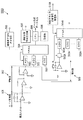
図1は第1実施形態のビーム位置モニタ50を備えた粒子線治療装置1の概略図である。図2は第1実施形態のビーム位置モニタ50の概略図である。
(First embodiment)
FIG. 1 is a schematic view of a particle
ビーム位置モニタ50を備えた粒子線治療装置1は、照射位置を変更するときも粒子線ビームを停止させないラスタースキャニング照射法により、被検体10の患部11に対し陽子や炭素などの粒子線を照射して癌治療を行うものである。
The particle
粒子線治療装置1は、図1に示すように、スキャニング電磁石20と、スキャニング電磁石用電源30と、線量モニタ40と、ビーム位置モニタ50と、リッジフィルタ60と、レンジシフタ70と、照射制御装置80とを備える。
As shown in FIG. 1, the particle
まず、粒子線治療装置1の基本動作について説明する。
First, the basic operation of the particle
粒子線治療装置1では、加速器(不図示)により粒子線が加速され、被検体10の患部11の位置する体内深度に応じたエネルギーを有した粒子線ビームとなってスキャニング電磁石20に入射する。スキャニング電磁石20はスキャニング電磁石用電源30により位置設定され、粒子線ビームはスキャニング電磁石20の設定位置に応じて、被検体10における粒子線ビーム軸に対する垂直面上の照射位置(X,Y)、即ち、図1に示すX方向及びY方向に走査される。
In the particle
スキャニング電磁石20により走査された粒子線ビームは線量モニタ40に入射して、被検体10の患部11に設定された照射点p1、p2、p3・・・の各照射点毎の照射線量が測定される。線量モニタ40としては、容器内で粒子線の電離作用により生じた電荷を平行電極で収集する電離箱や、容器内に配置された二次電子放出膜から放出される二次電子対を計測するSEM装置などが用いられる。
The particle beam scanned by the
線量モニタ40を経過した粒子線ビームは、ビーム位置モニタ50に入射してこのビーム位置モニタ50により粒子線ビームのビーム位置が予定した位置にあるかどうかが監視される。ビーム位置モニタ50としては、収集電極が格子状に分割されたマトリックス型、収集電極が複数のワイヤから成るマルチワイヤ型、収集電極が短冊状に分割されたストリップ型などが用いられる。
The particle beam that has passed through the
粒子線治療装置1に適用されたストリップ型のビーム位置モニタ50を図2に示す。ビーム位置モニタ50は、図2に示すように、1軸方向に配列され且つ電気的に接続されない多数の収集電極面要素たるストリップ53から構成され、粒子線ビームの軌道上に設定された収集電極51を有する。この収集電極51は複数設けられ、それぞれ導通面を有する高電圧電極により2〜10mm程度の間隔を保持して挟まれる。高電圧電極に対し高電圧が印加されると収集電極51と高電圧電極の間に電界が形成され、粒子線ビームが高電圧電極を通過した際の電離作用で生じる電荷が、この収集電極51により収集される。
A strip type
ビーム位置モニタ50は、収集電極51の有感領域52のうち特定のスポットPに入射した粒子線ビームをスポットビームとして検出し、照射位置(X,Y)に応じて走査された粒子線ビームが予定したスポットPに入射しているかどうかをビーム位置演算を行い監視する。粒子線ビームのビーム位置は、収集電極51の有感領域52のうち粒子線ビームが入射したスポットPが位置する領域のストリップ53にて収集された収集電荷の電気量をデジタル信号に変換し、その収集電荷に関するデジタル信号を用いて例えば粒子線ビームの重心位置を計算することにより特定される。
The beam position monitor 50 detects a particle beam incident on a specific spot P in the
ビーム位置モニタ50を経過した粒子線ビームは、リッジフィルタ60を経過した後に、厚さの異なる複数のアクリル板71から構成されるアクリル板群を有するレンジシフタ70に入射し、患部11の深度方向Z(図1参照)の位置、即ち患部11内部におけるビーム軸方向の照射位置(Z)が調節される。照射位置(Z)の調節は、アクリル板群から選択されるアクリル板71の組み合わせを適宜変更することにより、レンジシフタ70を通過する粒子線ビームのエネルギー調節即ち体内飛程を調節することにより行われる。なお、照射位置(Z)は、アクリル板71に粒子線を通過させて粒子線ビームのエネルギー調節を行うレンジシフタ70を用いるほか、電磁的作用で波長を調節し粒子線ビームのエネルギー調節を行う方法によっても調節できる。
After passing through the ridge filter 60, the particle beam having passed through the beam position monitor 50 enters a range shifter 70 having an acrylic plate group composed of a plurality of
なお、スキャニング電磁石20に入射した単エネルギーの粒子線ビームの線量ピーク(ブラッグピーク)は患部11でシャープな形状を示すが、レンジシフタ70の上流側に配置されるリッジフィルタ60により粒子線ビームのエネルギー分布が拡大され、患部11内の線量ピークが粒子線ビーム軸方向の照射幅に応じて拡大される。
The dose peak (Bragg peak) of a single energy particle beam incident on the
図3は第1実施形態の粒子線治療装置1における照射制御の流れを示すフローチャートである。この照射制御における各ステップに従う粒子線治療装置1における照射制御について説明する。各ステップは、照射位置を変更するときも粒子線ビームを停止させないラスタースキャニング照射法に関するものである。
FIG. 3 is a flowchart showing a flow of irradiation control in the particle
ステップS1:図3に示すように、被検体10における患部11が、粒子線ビーム軸に対して垂直方向に広がりを有する照射スライスに分割され、分割された照射スライスから1つの照射スライスが選択される。ここで、最深照射スライスが選択されたとすると、最深照射スライスの位置に応じて粒子線ビームの入射エネルギーとレンジシフタ70のアクリル板71の厚さが選択されてステップS2に移行する。
Step S1: As shown in FIG. 3, the affected
ステップS2:最深照射スライスにおける患部11の形状に応じて、患部11における粒子線ビームの照射点数n及び照射位置(Xi、Yi)[i=1〜n]が設定される。設定された照射位置(Xi,Yi)に応じてスキャニング電磁石20の位置調節が行なわれてステップ3に移行する。
Step S2: The number n of irradiation points and irradiation positions (Xi, Yi) [i = 1 to n] of the particle beam in the
ステップS3:ステップS1で設定された照射スライスのうちステップS2で設定された照射位置(Xi、Yi)の照射点に対して粒子線ビームの照射が開始され、ステップS4に移行する。 Step S3: The irradiation of the particle beam is started to the irradiation point at the irradiation position (Xi, Yi) set in Step S2 among the irradiation slices set in Step S1, and the process proceeds to Step S4.
ステップS4:照射位置(Xi,Yi)の照射点に対する照射線量が、その照射点に設定された設定線量に到達するまで粒子線ビームの照射が継続され、照射線量が設定線量に到達したことを示す線量満了信号が生成されたタイミングでステップ5に移行する。照射スライス上の照射位置(Xi、Yi)の照射線量は線量モニタ40によりモニタリングされる。
Step S4: The irradiation of the particle beam is continued until the irradiation dose to the irradiation point at the irradiation position (Xi, Yi) reaches the set dose set at the irradiation point, and the irradiation dose has reached the set dose. The process proceeds to step 5 at the timing when the dose expiration signal shown is generated. The irradiation dose at the irradiation position (Xi, Yi) on the irradiation slice is monitored by the
ステップS5:照射スライスに設定された全ての照射点が照射されたか否かが判定され、全ての照射点が照射されたと判定された場合はステップS6に移行する。一方、照射されていない照射点が残っている場合はステップS2に移行する。即ち、スキャニング電磁石20の位置が変更されて同一照射スライス上の次の照射位置(Xi+1、Yi+1)の照射が開始される。
Step S5: It is determined whether or not all irradiation points set in the irradiation slice have been irradiated. If it is determined that all irradiation points have been irradiated, the process proceeds to step S6. On the other hand, when the irradiation point which is not irradiated remains, it transfers to step S2. That is, the position of the
ステップS6:粒子線ビームの照射を停止し、ステップS7に移行する。 Step S6: The irradiation of the particle beam is stopped, and the process proceeds to Step S7.
ステップS7:すべての照射点が照射完了した照射スライスが最終照射スライスであったか否かが判定され、最終照射スライスであった場合は照射操作を終了する。一方、最終照射スライスでない場合はステップS1に移行する。即ち、次の照射スライスが選択されると共に選択された照射スライスの存在する照射位置(Z)及び照射スライス幅に応じてレンジシフタ70のアクリル板71の厚さが変更され、ステップS2〜ステップS7の制御が繰り返される。
Step S7: It is determined whether or not the irradiation slice for which all irradiation points have been irradiated is the final irradiation slice. If the irradiation slice is the final irradiation slice, the irradiation operation is terminated. On the other hand, if it is not the final irradiation slice, the process proceeds to step S1. That is, the next irradiation slice is selected, and the thickness of the
照射されるべき各照射位置(X,Y)の配置(照射パターン)は、照射パターンファイルに記述されており、照射治療の開始前に照射制御装置80に送られる。照射パターンファイルには、各照射位置(X,Y)に応じたレンジシフタ厚、照射位置(X,Y)を定めるスキャニング電磁石20の位置制御のための励磁電流(X方向駆動用及びY方向駆動用)、線量満了信号を生成するための線量条件等、各種管理情報が含まれる。
The arrangement (irradiation pattern) of each irradiation position (X, Y) to be irradiated is described in the irradiation pattern file, and is sent to the
図4は第1実施形態のビーム位置モニタ50の信号処理回路500を示すブロック図である。
FIG. 4 is a block diagram showing a
第1実施形態のビーム位置モニタ50の信号処理回路500は、図4に示すように、I/V変換器501と、増幅器502と、ADC(A/D変換)回路503と、ビーム位置演算部としてのFPGA504(Field Programmable Gate Array)と、線量満了信号送受信部505と、ビーム位置演算制御部としてのCPU506と、照射位置情報受信部507と、記憶部508とを有する。
As shown in FIG. 4, the
信号処理回路500において、I/V変換器501、増幅器502及びADC回路503はビーム位置モニタ50の収集電極51を構成する各ストリップ53(図2参照)のそれぞれに対して設けられ、各ADC回路503はFPGA504に接続される。また、FPGA504には線量満了信号送受信部505及びCPU506が接続され、CPU506には照射位置情報受信部507及び記憶部508が接続される。以下、1つのストリップ53及びこのストリップ53に対して接続されたI/V変換器501、増幅器502及びADC回路503から構成される1つのラインをチャンネルと称す。
In the
信号処理回路500において、I/V変換器501はビーム位置モニタ50の収集電極51で収集された収集電荷の電気量を示す電流出力をI/V変換して電圧信号に変換し、増幅器502はI/V変換された電圧信号を増幅する。
In the
信号処理回路500のADC回路503は、信号処理回路500のFPGA504により送信されるA/D変換開始信号を受信したタイミングで、増幅器502により増幅された電圧信号を収集電荷の電気量に応じたデジタル信号へとA/D変換し、収集電荷に関するデジタル信号を生成する。
The
信号処理回路500の線量満了信号送受信部505は、ある照射点に照射された線量がその照射点に対して設定された線量に到達したことを示す線量満了信号を受信し、受信した線量満了信号をFPGA504に送信する。
The dose expiration signal transmission /
信号処理回路500のFPGA504は、線量満了信号送受信部505から線量満了信号を受信したことを条件に、各ADC回路503に対してA/D変換を実行させる条件となるA/D変換開始信号を送信する。また、信号処理回路500の各ADC回路503により生成された収集電荷に関するデジタル信号を内蔵メモリ(不図示)に一時記憶し、記憶したデジタル信号を用いて粒子線ビームのビーム位置を算出するためのビーム位置演算を行う。なお、収集電荷に関するデジタル信号を信号処理回路500の記憶部508に一時記憶させ、信号処理回路500のFPGA504は、記憶部508に記憶させたデジタル信号を用いてビーム位置演算を行うようにしてもよい。
The
信号処理回路500の照射位置情報受信部507は、次に照射されるべき停止照射点の位置を示す照射位置情報を、この停止照射点の照射直前に受信する。
The irradiation position
信号処理回路500のCPU506は、照射位置情報受信部507が受信した照射位置情報をFPGA504に伝送し、また、FPGA504によるビーム位置演算に用いられ、ADC回路503により生成される全チャンネルの収集電荷に関するデジタル信号を記憶部508に伝送する。
The
なお、ビーム位置モニタ50の信号処理回路500の構成に関し、増幅器502にはADC回路503が直接接続されるが、増幅器502とADC回路503の間にサンプルホールド回路を介設し、増幅器502から送られてくる電圧信号を一定時間ホールドした後にADC回路503にてA/D変換を行うようにしてもよい。サンプルホールド回路を介設することによりADC回路503に対する電圧信号の入力値が変化してもA/D変換を正常に行うようにでき、ビーム位置測定の精度向上に有効である。
Regarding the configuration of the
次に、ビーム位置モニタ50の作用を説明する。 Next, the operation of the beam position monitor 50 will be described.
ここで、作用説明に入る前に背景技術並びに本願発明に至る経緯について説明する。 Here, the background to the background art and the background to the present invention will be described before the description of the operation.
図5は従来のビーム位置モニタの信号処理回路500aを示すブロック図である。図6は従来の粒子線治療装置1におけるビーム位置測定に関わるタイミングチャートである。
FIG. 5 is a block diagram showing a
図5に示すように、従来のビーム位置モニタ(不図示)の信号処理回路500aは、ビーム位置モニタの収集電極のチャンネル毎に、I/V変換器501aと、増幅器502aと、積分器509aと、ADC回路503aとを有して構成される。
As shown in FIG. 5, a
従来のビーム位置モニタの信号処理回路500aは、照射位置に対して2桁にわたる照射時間のばらつきに基づく収集電荷の積分値のばらつきに対して精度を確保すべく容量の異なる3つのコンデンサCを有し、3つのコンデンサCが切り替えられて使用される。このため、複雑な回路構成を呈してビーム位置モニタの小型化及び低コスト化が困難となっている。
The
加えて、従来のビーム位置モニタの信号処理回路500aでは、図6に示すように、線量満了信号の生成を条件として、ビーム位置モニタの収集電極で収集される収集電荷の積分開始・積分停止が行なわれるがその積分処理は線量満了信号の生成の前後連続して行なわれる。このようにして積算される電荷には、粒子線ビームの停止照射点における電荷だけでなく、図6に示すように、スキャニング電磁石20を駆動させる励磁電流X及び励磁電流Yが一定でない状態、換言すると線量満了信号が生成された後から次の線量満了信号が生成されるまでの粒子線ビームの走査中の電荷も含まれる。そのため、粒子線ビームの走査途中の位置で収集された電荷と走査完了の位置で収集された電荷とが正確に区別されないことが要因となってビーム位置測定の精度が低下する。特に、ある停止照射点から次の停止照射点までの距離が大きいと、ビーム位置モニタのビーム位置測定精度の低下度合いも大きくなる。
In addition, in the
そこで、従来のビーム位置モニタの構成及びビーム位置測定の原理を採用することなく、ビーム位置測定精度の向上という要求に応じるべく本実施形態の粒子線治療装置用のビーム位置モニタ50が為された。粒子線治療装置用のビーム位置モニタ50にあっては、線量満了信号が生成された後から次の線量満了信号が生成されるまで電荷を極力収集することなくビーム位置演算が行われるので、ビーム位置測定の精度が向上するだけでなく、信号処理回路の構成が簡略化されてビーム位置モニタの小型化及び低コスト化が実現される。以下、第1実施形態の粒子線治療装置用のビーム位置モニタの作用を説明する。 Accordingly, the beam position monitor 50 for the particle beam therapy system according to the present embodiment has been made to meet the demand for improved beam position measurement accuracy without adopting the configuration of the conventional beam position monitor and the principle of beam position measurement. . In the beam position monitor 50 for the particle beam therapy system, the beam position calculation is performed without collecting the charges as much as possible after the dose expiration signal is generated until the next dose expiration signal is generated. Not only the accuracy of position measurement is improved, but the configuration of the signal processing circuit is simplified, and the beam position monitor can be reduced in size and cost. Hereinafter, the operation of the beam position monitor for the particle beam therapy system according to the first embodiment will be described.
図7は第1実施形態の粒子照射療装置1におけるビーム位置測定に関わるタイミングチャートである。
FIG. 7 is a timing chart relating to beam position measurement in the particle
粒子線治療装置1にあっては、患部11の照射位置(X,Y)に対する照射線量が照射位置(X,Y)に対する設定値に到達すると線量満了信号が生成される。線量満了信号が生成されると、図7に示すように、線量満了信号が生成されたタイミングでスキャニング電磁石20を駆動させる励磁電流X及び励磁電流Yが変更開始されて、粒子線ビームの照射位置(X,Y)が変更開始される。励磁電流Xは粒子線ビームの照射位置(X)の変更に用いられ、励磁電流Yは粒子線ビームの照射位置(Y)の変更に用いられる。励磁電流X及び励磁電流Yが設定値に到達すると励磁電流X及び励磁電流Yは一定の値で保持され、照射位置設定完了信号が生成される。
In the particle
照射位置(X,Y)の変更開始条件となる線量満了信号は、信号処理回路500の線量満了信号送受信部505により受信されると共に受信された線量満了信号は信号処理回路500のFPGA504に伝送される。
A dose expiration signal that is a condition for starting to change the irradiation position (X, Y) is received by the dose expiration signal transmission /
信号処理回路500のFPGA504が線量満了信号を受信すると、FPGA504から信号処理回路500の各チャンネルに接続されたADC回路503に対してA/D変換開始信号が送信される。
When the
各ADC回路503がA/D変換信号を受信したタイミングで、信号処理回路500のI/V変換器501により生成された電圧信号が、各ADC回路503により収集電荷の電気量に応じたデジタル信号へとA/D変換され、収集電荷に関するデジタル信号が生成される。
At the timing when each
各ADC回路503により生成されたデジタル信号は信号処理回路500のFPGA504に送信され、FPGA504の内臓メモリに一時保存される。線量満了信号は、停止照射点から次の停止照射点に走査される粒子線ビームが走査されていない状態を示すタイミング信号として用いられ、各ADC回路503のA/D変換により生成される収集電荷に関するデジタル信号は、粒子線ビームが走査途中でない状態の収集電荷に関するものとなる。
The digital signal generated by each
一方、信号処理回路500の照射位置情報受信部507により、治療計画で決められた照射位置情報、即ち各照射点の存在する照射位置のうち次に照射されるべき停止照射点の位置を示す情報が各照射点毎にその照射直前に読み込まれる。
On the other hand, the irradiation position
照射位置情報受信部507が受信した照射位置情報が信号処理回路500のCPU506により参照され、CPU506により、次に照射されるべき停止照射点に走査される粒子線ビームが入射する収集電極51上の位置乃至は入射する位置周辺に位置するスポットPにストリップ53が判別される。
The irradiation position information received by the irradiation position
CPU506は、FPGA504によるビーム位置演算に用いられる収集電荷に関するデジタル信号を、判別したストリップ53に接続されたADC回路503で生成されたデジタル信号に限定する。即ち、信号処理回路500にあっては、収集電極51の有感領域52のうち粒子線ビームが入射すべきスポットPが照射位置(X,Y)の照射前に予想される。
The
FPGA504は、収集電極51を構成する全てのストリップ53のうち粒子線ビームが入射すると予想されたスポットPの位置周辺のチャンネルに接続されたADC回路503で生成された収集電荷に関するデジタル信号を用いてビーム位置演算を実行する。
The
なお、CPU506に接続される記憶部508には、全チャンネルに対する収集電荷のデジタル信号の保存が可能であるが、CPU506による信号処理制御を受けて粒子線ビームが入射すると予想されたスポットP或いはスポットP周辺のチャンネルに接続されるADC回路503で生成されたデジタル信号が選択的に伝送・記憶される。その他のチャンネルに接続されるADC回路503で生成されたデジタル信号は記憶部508に伝送・記憶されない。即ち、ADC回路503により生成された収集電荷に関するデジタル信号のうち、FPGA504によるビーム位置演算に用いられる収集電荷に関するデジタル信号が選択的に記憶部508に対して伝送・記憶され、FPGA504によるビーム位置演算に用いられない収集電荷に関するデジタル信号については記憶部508に対して伝送・記憶されない。
Note that the
次に、ビーム位置モニタ50の効果を説明する。 Next, the effect of the beam position monitor 50 will be described.
ビーム位置モニタ50にあっては、
(1)被検体10に設定された複数の停止照射点に粒子線ビームを照射し、この停止照射点に照射された線量が設定値に到達したときに、粒子線ビームの照射位置を次の停止照射点に走査する粒子線治療装置としての粒子線治療装置1に設けられ、粒子線ビームの軌道上に設定された収集電極51と、この収集電極51に対して粒子線ビームが入射した際の電離作用で生じる電荷を収集電荷として収集し、この収集電荷を利用してビーム位置を特定するためのビーム位置演算を行う信号処理回路500を備えたビーム位置モニタ50において、信号処理回路500は、収集電極51における電離作用で生じた電流出力をI/V変換して電流出力に応じた電圧信号を生成するI/V変換器501と、I/V変換器501により生成された電圧信号の入力を受けて収集電荷に関するデジタル信号を生成するデジタル信号生成回路と、前記停止照射点から次の停止照射点に走査される粒子線ビームが走査されていない非走査状態で生成される信号をタイミング信号として受信するタイミング信号送受信部と、前記タイミング信号送受信部がタイミング信号を受信したタイミングで、前記デジタル信号生成回路により生成された収集電荷に関するデジタル信号の入力を受けて、入力を受けた収集電荷に関するデジタル信号を用いて前記ビーム位置演算を行なうFPGA504とを有する。
In the beam position monitor 50,
(1) A plurality of stop irradiation points set on the subject 10 are irradiated with a particle beam, and when the dose irradiated to the stop irradiation point reaches a set value, the irradiation position of the particle beam is When the particle beam is incident on the
そのため、収集電極51にて収集されてビーム位置演算に用いられる収集電荷から粒子線ビームの照射位置を走査している途中で収集される収集電荷が排除され、ビーム位置測定の精度低下を回避できる。
For this reason, the collected charges collected during the scanning of the irradiation position of the particle beam from the collected charges collected by the collecting
また、照射時間のばらつきに基づく収集電荷の電気量のばらつきに対応して収集電荷の電気量を精度よく測定すべく、容量の異なる複数のコンデンサを用いてビーム位置モニタ50の信号処理回路500を構成する必要がない。したがって、信号処理回路500及びビーム位置モニタ50の簡略化、低コスト化が図られる。
In addition, the
即ち、粒子線治療装置用のビーム位置モニタ50にあっては、ラスタースキャニング法にあっても粒子線ビームのビーム位置を精度よく測定し且つビーム位置モニタの小型化及び低コスト化が図れる。 That is, in the beam position monitor 50 for the particle beam therapy system, the beam position of the particle beam can be accurately measured even in the raster scanning method, and the size and cost of the beam position monitor can be reduced.
(2)信号処理回路500は、I/V変換器501とデジタル信号生成回路との間に介設され、I/V変換器により生成されてデジタル信号生成回路に入力される電圧信号を増幅する増幅器502を有する。そのため、粒子線ビームの入射による収集電極51おける電離作用が微弱であっても、収集電荷に関するデジタル信号を安定して生成できる。したがって、粒子線ビームのビーム位置を精度よく特定できる。
(2) The
(3)デジタル信号生成回路は、I/V変換器501により生成された電圧信号をA/D変換し、電圧信号の大小に応じた収集電荷に関するデジタル信号を生成するADC回路503により構成される。そのため、ビーム位置演算を計算機にて実行できる。
(3) The digital signal generation circuit includes an
(4)タイミング信号送受信部は、被検体10の停止照射点に照射された線量がその停止照射点に対して設定された線量に到達したことを示す線量満了信号を前記タイミング信号として受信し、受信した線量満了信号をFPGA504に送信する線量満了信号送受信部505により構成され、FPGA504は、線量満了信号を受信したタイミングで、デジタル信号生成回路(例えば、ADC回路503)に対して収集電荷に関するデジタル信号の生成を許容して、生成されたデジタル信号を受け取る。そのため、粒子線ビームの照射位置を走査している途中で積分される収集電荷の電気量に起因するビーム位置の測定精度の低下を回避し易いものとなる。したがって、(1)の効果が堅実となる。
(4) The timing signal transmission / reception unit receives a dose expiration signal indicating that the dose irradiated to the stop irradiation point of the subject 10 has reached the dose set for the stop irradiation point, as the timing signal, The dose expiration signal transmission /
(5)ビーム位置モニタ50の収集電極51は、独立した複数の収集電極要素たるストリップ53の配列により構成され、信号処理回路500のI/V変換器501は、各ストリップのそれぞれに対して設けられて各ストリップにおける電離作用で生じる電流出力をI/V変換し、信号処理回路500のデジタル信号生成回路は、各I/V変換器501のそれぞれに対して設けられて各I/V変換器501により生成された電圧信号の入力を受けて収集電荷に関するデジタル信号を生成するよう構成され、信号処理回路500は、次に照射されるべき停止照射点に走査される粒子線ビームが入射する位置乃至は入射する位置周辺のストリップ53を判別し、信号処理回路500のFPGA504に対し、判別したストリップ53に対して設けられたデジタル信号生成回路により生成されたデジタル信号を用いたビーム位置演算を許容し、判別した収集電極要素以外のストリップ53に対して設けられたデジタル信号生成回路により生成されたデジタル信号を用いたビーム位置演算を禁止するCPU506を有する。
(5) The
そのため、信号処理回路500のFPGA504が備える内部メモリ及び記憶部508に対するビーム位置演算に用いられるデジタル信号の伝送、保存及び取り出しの各処理にかかる時間を短縮できる。従って、ビーム位置演算の精度を向上できる。具体的に説明すると、照射点の照射時間が短い場合にあっては、特に、各照射点に関して生成されたデジタル信号の記憶部508等に対する伝送、保存等の各処理が追いつけなくなるというデータ処理落ちが問題となる。しかし、一般的な粒子線照射治療1においては、ビーム位置モニタ50の収集電極51に含まれる数十チャンネルのうち一時に有効となるチャンネルは数チャンネルであることが多い。この点に着目し、ビーム位置モニタ50の信号処理回路500にあっては、粒子線ビームが入射するスポットに対応するチャンネル即ちストリップ53を判別し、判別したストリップ53にて収集された収集電極に関するデジタル信号に限定して信号処理回路500の記憶部508等に伝送・保存するので、上記データ処理落ちの問題を低減でき、ビーム位置演算の精度を向上させることができる。
Therefore, it is possible to shorten the time required for each process of transmission, storage, and extraction of a digital signal used for beam position calculation with respect to the internal memory and
(6)信号処理回路500は、次に照射されるべき停止照射点の位置を示す照射位置情報を、次に照射されるべき停止照射点の照射前に受信する照射位置情報受信部507を有するため、(5)の効果が実現容易となる。
(6) The
(7)信号処理回路500は、デジタル信号生成回路により生成された収集電荷に関するデジタル信号のうち、FPGA504のビーム位置演算に用いられる収集電荷に関するデジタル信号を選択的に記憶し、FPGA504のビーム位置演算に用いられない収集電荷に関するデジタル信号は記憶しない記憶部508を有する。そのため、記憶部508に対するデジタル信号の伝送・保存に必要な時間を短縮でき、(5)の効果を向上できる。なお、記憶するデジタル信号の選択方法として、たとえばビーム位置演算によって得られたビーム入射位置の周辺チャンネルを選択する方法があるが、あらかじめ照射位置情報を取得しておくことにより高速なデジタル信号の選択が可能になる。
(7) The
(第2実施形態)
第2実施形態は、第1実施形態のビーム位置モニタ50の信号処理回路500に他の信号処理回路要素を追加した例である。なお、第1実施形態と同様の構成は、対応する構成に同一符号を付して説明を省略する。第1実施形態の構成を変更したり追加した構成は、符号末尾に「A」を付して説明する。
(Second Embodiment)
The second embodiment is an example in which other signal processing circuit elements are added to the
図8は第2実施形態のビーム位置モニタ50Aの信号処理回路500Aを示すブロック図である。
FIG. 8 is a block diagram showing a
ビーム位置モニタ50Aの信号処理回路500Aは、図8に示すように、第1実施形態の信号処理回路500に加え、スライス照射線量積分器としての積分器509Aと、サンプルホールド回路510Aと、ADC回路503Aと、FPGA504Aと、照射スライス切替信号受信部511Aとを備える。第1実施形態の信号処理回路500に対応する信号処理回路を第1信号ラインと称し、第1信号ラインに追加した信号処理回路を第2信号ラインと称す。
As shown in FIG. 8, the
信号処理回路500Aの第2信号ラインは、ビーム位置モニタ50Aの収集電極51の各ストリップ53に設けられた第1信号ラインの増幅器502出力側から分岐して設けられ、第1信号ラインと第2信号ラインとにより1つのチャンネルを構成する。そして、第2信号ラインのFPGA504Aには照射スライス切替信号受信部511が接続される。
The second signal line of the
信号処理回路500Aにおいて、第2信号ラインの積分器509Aは、照射スライス切替信号送受信部511Aが照射スライス切替信号を受信したときは、照射スライス切替信号送受信部511Aが次の照射スライス切替信号を受信するまで、収集電極51において粒子線ビームが入射するスポットPに位置している各ストリップ53にて収集された収集電荷に関する電気量を積算する。
In the
第2信号ラインのサンプルホールド回路510Aは、積分器509Aから送られてくる電圧信号を一定時間ホールドする。サンプルホールド回路510Aは必ずしも必要ではないが、サンプルホールド回路510Aを設けることにより第1信号ラインのI/V変換器501で生成されて第2信号ラインのADC回路503Aに入力される電圧信号の入力値が変化してもA/D変換を正常に行うようにでき、ビーム位置測定の精度向上に有効である。
The sample and hold
第2信号ラインの照射スライス切替信号受信部511Aは、被検体の照射スライスの照射を開始する条件となり、照射スライスに設定された複数の停止照射点の照射がすべて完了したときは照射スライスを切り替える条件となる照射スライス切替信号を受信する。 The irradiation slice switching signal receiving unit 511A of the second signal line is a condition for starting irradiation of the irradiation slice of the subject, and switches irradiation slices when irradiation of a plurality of stop irradiation points set in the irradiation slice is completed. An irradiation slice switching signal as a condition is received.
次に、ビーム位置モニタ50Aの作用を説明する。 Next, the operation of the beam position monitor 50A will be described.
ビーム位置モニタ50Aによるビーム位置測定は、第1実施形態と同様、図7に示すタイミングに従って行なわれる。一方、ビーム位置モニタ50Aでは、照射スライスを切り替えるための照射スライス切替信号が生成されると、信号処理回路500Aにおける第2信号ラインにおいて、生成された照射スライス切替信号が照射スライス切替信号送受信部511により受信され、FPGA504Aに伝送される。
The beam position measurement by the beam position monitor 50A is performed according to the timing shown in FIG. 7 as in the first embodiment. On the other hand, in the beam position monitor 50A, when the irradiation slice switching signal for switching the irradiation slice is generated, the generated irradiation slice switching signal is transmitted to the irradiation slice switching signal transmission / reception unit 511 in the second signal line in the
FPGA504Aが照射スライス切替信号を受信したタイミングで、FPGA504Aによる制御を受けて第1信号ラインのI/V変換器501で生成されて第2信号ラインの積分器509Aで積算された収集電荷に関する電圧信号がクリア(ディスチャージON)されると共に、I/V変換器501で生成された収集電荷に関する電圧信号が積分器509Aにより積算開始される(ディスチャージOFF)。
At the timing when the
第2信号ラインにおいて、積分器509Aで積算された収集電荷に関する電圧信号は、サンプルホールド回路510Aにより一旦ホールドされた後、ADC回路503AによりA/D変換されて収集電荷に関するデジタル信号が生成される。生成されたデジタル信号は、第2信号ラインのFPGA504Aに入力されて、各照射スライスに照射された線量積算演算が行なわれる。そして、次の照射スライス切替信号が生成されたタイミングで、次の照射スライスに対して同様の線量積算演算が行なわれる。なお、他の作用は、第1実施形態と同様であるので、説明を省略する。
In the second signal line, the voltage signal related to the collected charge integrated by the integrator 509A is temporarily held by the
次に、ビーム位置モニタ50Aの効果を説明する。 Next, the effect of the beam position monitor 50A will be described.
ビーム位置モニタ50Aにあっては、第1実施形態の(1)〜(7)の効果に加え、下記の効果を得ることができる。 In the beam position monitor 50A, in addition to the effects (1) to (7) of the first embodiment, the following effects can be obtained.
(8)信号処理回路500Aは、被検体10が複数の照射スライスに分割されたときは、この照射スライスの照射を開始する条件となり、照射スライスに設定された複数の停止照射点の照射がすべて完了したときは照射スライスを切り替える条件となる照射スライス切替信号を受信する照射スライス切替信号送受信部511Aと、前記照射スライス切替信号送受信部511Aが照射スライス切替信号を受信したときは、照射スライス切替信号送受信部511Aが次の照射スライス切替信号を受信するまで、前記照射スライスに設定された複数の停止照射点の照射線量を積算する積分器509Aとを有する。
(8) When the subject 10 is divided into a plurality of irradiation slices, the
そのため、治療計画により照射スライスに設定された最初の照射点から最後の照射点までの照射線量の総和を取得することができる。したがって、照射が正常に行われているかどうかを確認する上で照射位置だけでなく照射線量を確認したいという医師や粒子線治療装置を運用する技師の要望に応えることができ、信頼性の高い粒子線治療が実現される。 Therefore, the total sum of irradiation doses from the first irradiation point to the last irradiation point set in the irradiation slice by the treatment plan can be acquired. Therefore, it is possible to meet the demands of doctors and technicians who operate particle beam therapy equipment that want to check not only the irradiation position but also the irradiation dose in confirming whether irradiation is performed normally, and highly reliable particles Line therapy is realized.
なお、呼吸同期照射(例えば、非特許文献1参照)のように1つの照射スライスの照射中に一時的に照射停止或いは照射部位移行が行なわれる場合は、1つの照射スライスに対する照射線量を積算する際に第2信号ラインの積分器509Aに対して収集電荷に関する電圧信号が入力されないよう、例えば増幅器502の増幅率を低減させることが望ましい。
In addition, when the irradiation is temporarily stopped or the irradiation part is shifted during irradiation of one irradiation slice as in the case of respiratory synchronization irradiation (for example, see Non-Patent Document 1), the irradiation dose for one irradiation slice is integrated. At this time, for example, it is desirable to reduce the amplification factor of the
ここで、照射スライスの照射を開始する条件となり、照射スライスに設定された照射パターンに含まれる停止照射点の照射がすべて完了したときは照射パターンを切り替える条件となる照射パターン切替信号を生成させるようにし、照射スライス切替信号送受信部511Aに代えて照射パターン切替信号を受信する照射パターン切替信号送受信部と、この照射パターン切替信号送受信部が照射パターン切替信号を受信したときは、照射パターン切替信号送受信部が次の照射パターン切替信号を受信するまで、照射パターンに含まれる停止照射点の照射線量を積算する照射パターン照射線量積分器とを設けるようにしてもよい。この構成によっても、同一照射スライスの同一或いは異なる照射パターンに対する照射線量の総和を取得でき、(8)と同様の効果を得ることができる。 Here, it becomes a condition for starting irradiation of the irradiation slice, and when irradiation of the stop irradiation points included in the irradiation pattern set in the irradiation slice is completed, an irradiation pattern switching signal that is a condition for switching the irradiation pattern is generated. The irradiation pattern switching signal transmission / reception unit that receives the irradiation pattern switching signal instead of the irradiation slice switching signal transmission / reception unit 511A, and when the irradiation pattern switching signal transmission / reception unit receives the irradiation pattern switching signal, You may make it provide the irradiation pattern irradiation dose integrator which integrates the irradiation dose of the stop irradiation point contained in an irradiation pattern until a part receives the next irradiation pattern switching signal. Also with this configuration, it is possible to obtain the sum of irradiation doses for the same or different irradiation patterns of the same irradiation slice, and the same effect as in (8) can be obtained.
(第3実施形態)
第3実施形態は、第1実施形態のビーム位置モニタ50の信号処理回路500の構成を変更した例である。なお、第1実施形態と同様の構成は、対応する構成に同一符号を付して説明を省略し、第1実施形態の構成を変更し或いは追加した構成は、符号末尾に「B」を付して説明する。
(Third embodiment)
The third embodiment is an example in which the configuration of the
図9は第3実施形態のビーム位置モニタ50Bの信号処理回路500Bを示すブロック図である。
FIG. 9 is a block diagram showing a
ビーム位置モニタ50Bの信号処理回路500Bは、図9に示すように、第1実施形態の信号処理回路500におけるADC回路503に代えて、コンパレータ回路512Bを設けたものである。信号処理回路500Bのコンパレータ回路512Bは、ビーム位置モニタ50Bの収集電極51の各ストリップ53毎に設けられたI/V変換器501のそれぞれに対して設けられ、信号処理回路500BのFPGA504に接続される。
As shown in FIG. 9, the
信号処理回路500Bのコンパレータ回路512Bは、信号処理回路500BのI/V変換器501で生成された収集電荷に応じた電圧が予め設定された基準電圧レベルを超えることを示す有効デジタル信号、及びI/V変換器501で生成された収集電荷に応じた電圧信号が基準電圧レベルを超えないことを示す無効デジタル信号から成る2つの判定用デジタル信号を生成し、生成した判定用デジタル信号を信号処理回路500BのFPGA504に送信する。判定用デジタル信号としては、例えば、コンピュータが扱う最小の情報単位を用いて、有効デジタル信号に対しては「1」を割り当て、無効デジタル信号に対しては「0」を割り当てる。
The
そして、信号処理回路500BのFPGA504は、ビーム位置モニタ50Bの収集電極51を構成する各ストリップ53のうち有効デジタル信号を生成したコンパレータ回路512が設けられたストリップの位置を粒子線ビームが入射した位置であるとする内容のビーム位置演算を行う。
Then, the
次に、ビーム位置モニタ50Bの作用を説明する。 Next, the operation of the beam position monitor 50B will be described.
ビーム位置モニタ50Bの信号処理回路500Bにおけるビーム位置測定は、第1実施形態と同様、図7に示すタイミングに従って行なわれる。但し、線量満了信号が生成されたときは、第1実施形態のADC回路503による収集電荷に関するデジタル信号の生成に代えて、信号処理回路500Bのコンパレータ回路512Bによる判定用デジタル信号が生成される。
The beam position measurement in the
信号処理回路500Bの線量満了信号送受信部505が線量満了信号を受信して線量満了信号が信号処理回路500BのFPGA504に伝送されたタイミングで、FPGA504からコンパレータ回路512Bにコンパレータ回路動作信号が送信される。そして、コンパレータ回路512Bがコンパレータ回路動作信号を受信したとき、コンパレータ回路512BからFPGA504に判定用デジタル信号が送信される。
The comparator circuit operation signal is transmitted from the
信号処理回路500BにおいてFPGA504がコンパレータ回路512Bから判定用デジタル信号を受信すると、受信した判定用デジタル信号を用いたビーム位置演算がFPGA504において行われる。即ち、FPGA504において、ビーム位置モニタ50Bの収集電極51を構成するストリップ53のうち有効デジタル信号を生成したコンパレータ回路512Bが接続されたストリップの位置が粒子線ビームが入射したスポットであると判定される。なお、信号処理回路500BのFPGA504が受信した判定用デジタル信号はFPGA504の内部メモリに一時保存され、FPGA504は保存された判定用デジタル信号を用いてビーム位置演算を行う。なお、他の作用は、第1実施形態と同様であるので、説明を省略する。
When the
次に、粒子照射装置用のビーム位置モニタ50Bの効果を説明する。 Next, the effect of the beam position monitor 50B for the particle irradiation apparatus will be described.
第3実施形態のビーム位置モニタ50Bにあっては、第1実施形態の(1)、(2)、(4)〜(7)の効果に加え、下記の効果を得ることができる。 In the beam position monitor 50B of the third embodiment, the following effects can be obtained in addition to the effects (1), (2), (4) to (7) of the first embodiment.
(9)ビーム位置モニタ50Bの収集電極51は、独立した複数の収集電極要素たるストリップ53の配列により構成され、I/V変換器501は、各ストリップ53のそれぞれに対して設けられて各ストリップ53における電離作用で生じる電流出力をI/V変換し、デジタル信号生成回路は、各I/V変換器501のそれぞれに対して設けられ、各I/V変換器501により生成された電圧信号の入力を受けて、受け取った電圧信号が基準電圧レベルを超えることを示す有効デジタル信号と、その電圧信号が基準電圧レベルを超えないことを示す無効デジタル信号の2つの判定用デジタル信号を生成するコンパレータ回路512Bにより構成され、FPGA504は、各コンパレータ回路512Bにより生成された判定用デジタル信号を入力可能に設けられ、有効デジタル信号を用いたビーム位置演算を行ない、無効デジタル信号を用いたビーム位置演算を行なわない。
(9) The
そのため、ビーム位置演算の実行にあたって、I/V変換器501により生成される電圧信号をA/D変換して生成される収集電荷の電気量に応じたデジタル信号を用いる場合に比べて、信号処理回路500BのFPGA504が扱うデータサイズ(ビット数)を小さくすることができ、演算時間を短縮することができる。したがって、ビーム位置演算の処理速度を高速化できる。
Therefore, in the execution of the beam position calculation, signal processing is performed as compared with a case where a digital signal corresponding to the amount of electricity of collected charges generated by A / D converting the voltage signal generated by the I /
(第4実施形態)
第4実施形態は、第3実施形態のビーム位置モニタ50Bの信号処理回路500Bに他の信号処理回路要素を追加した例である。なお、第3実施形態と同様の構成は、対応する構成に同一符号を付して説明を省略し、第3実施形態の構成を変更し或いは追加した構成は、符号末尾に「C」を付して説明する。
(Fourth embodiment)
The fourth embodiment is an example in which other signal processing circuit elements are added to the
図10は第4実施形態のビーム位置モニタ50Cの信号処理回路500Cを示すブロック図である。 FIG. 10 is a block diagram showing a signal processing circuit 500C of the beam position monitor 50C of the fourth embodiment.
ビーム位置モニタ50Cおける信号処理回路500Cは、図10に示すように、第3実施形態の信号処理回路500Bに加え、スライス照射線量積分器としての積分器509Cと、サンプルホールド回路510Cと、ADC回路503Cと、FPGA504Cと、照射スライス切替信号受信部511Cとを備える。以下、第3実施形態の信号処理回路500に対応する信号処理回路を第1信号ラインと称し、第1信号ラインに追加した信号処理回路を第2信号ラインと称す。
As shown in FIG. 10, the signal processing circuit 500C in the beam position monitor 50C includes an
信号処理回路500Cにおいて、第2信号ラインの積分器509Cは、照射スライス切替信号送受信部511Cが照射スライス切替信号を受信したときは、照射スライス切替信号送受信部511Cが次の照射スライス切替信号を受信するまで、収集電極51において粒子線ビームが入射するスポットPに位置している各ストリップ53にて収集された収集電荷に関する電気量を積算する。
In the signal processing circuit 500C, when the irradiation slice switching signal transmission / reception unit 511C receives the irradiation slice switching signal, the irradiation slice switching signal transmission / reception unit 511C receives the next irradiation slice switching signal. Until then, the amount of electricity related to the collected charge collected in each
第2信号ラインのサンプルホールド回路510Cは、積分器509Cから送られてくる電圧信号を一定時間ホールドする。サンプルホールド回路510Cは必ずしも必要ではないが、サンプルホールド回路510Cを設けることにより第1信号ラインのI/V変換器501で生成されて第2信号ラインのADC回路503Cに入力される電圧信号の入力値が変化してもA/D変換を正常に行うようにでき、ビーム位置測定の精度向上に有効である。
The sample and hold circuit 510C for the second signal line holds the voltage signal sent from the
第2信号ラインの照射スライス切替信号受信部511Cは、被検体10の照射スライスの照射を開始する条件となり、照射スライスに設定された複数の停止照射点の照射がすべて完了したときは照射スライスを切り替える条件となる照射スライス切替信号を受信する。 The irradiation slice switching signal receiving unit 511C of the second signal line is a condition for starting irradiation of the irradiation slice of the subject 10, and when irradiation of a plurality of stop irradiation points set in the irradiation slice is completed, the irradiation slice is selected. An irradiation slice switching signal as a switching condition is received.
次に、ビーム位置モニタ50Cの作用を説明する。 Next, the operation of the beam position monitor 50C will be described.
ビーム位置モニタ50Cの信号処理回路500Cによるビーム位置測定は、第1実施形態と同様、図7に示すタイミングに従って行なわれる。ビーム位置モニタ50Cでは、照射スライスを切り替えるための照射スライス切替信号が生成されると、照射スライス切替信号が第2信号ラインの照射スライス切替信号送受信部511Cにより受信され、FPGA504Cに伝送される。 The beam position measurement by the signal processing circuit 500C of the beam position monitor 50C is performed according to the timing shown in FIG. 7, as in the first embodiment. In the beam position monitor 50C, when an irradiation slice switching signal for switching irradiation slices is generated, the irradiation slice switching signal is received by the irradiation slice switching signal transmission / reception unit 511C of the second signal line and transmitted to the FPGA 504C.
第2信号ラインのFPGA504Cが照射スライス切替信号を受信したタイミングでFPGA504Cによる制御を受けて第1信号ラインのI/V変換器501で生成されて第2信号ラインの積分器509Cで積算された収集電荷に関する電圧信号がクリア(ディスチャージON)されると共に、I/V変換器501で生成された収集電荷に関する電圧信号が積分器509Cにより積算開始される(ディスチャージOFF)。
Collection that is generated by the I /
第2信号ラインにおいて、積分器509Cで積算された収集電荷に関する電圧信号は、サンプルホールド回路510Cにより一旦ホールドされた後、ADC回路503CによりA/D変換されて収集電荷に関するデジタル信号が生成される。生成されたデジタル信号は、第2信号ラインのFPGA504Cに入力されて、各照射スライスに照射された線量積算演算が行なわれる。そして、次の照射スライス切替信号が生成されたタイミングで、次の照射スライスに対して同様の線量積算演算が行なわれる。なお、他の作用は、第3実施形態と同様であるので、説明を省略する。
In the second signal line, the voltage signal related to the collected charge accumulated by the
次に、ビーム位置モニタ50Cの効果を説明する。 Next, the effect of the beam position monitor 50C will be described.
ビーム位置モニタ50Cにあっては、第1実施形態の(1)、(2)、(4)〜(7)、及び第3実施形態の(9)の効果に加え、下記の効果を得ることができる。 In the beam position monitor 50C, in addition to the effects of (1), (2), (4) to (7) of the first embodiment and (9) of the third embodiment, the following effects can be obtained. Can do.
(10) 信号処理回路500Cは、被検体10が複数の照射スライスに分割されたときは、この照射スライスの照射を開始する条件となり、照射スライスに設定された複数の停止照射点の照射がすべて完了したときは照射スライスを切り替える条件となる照射スライス切替信号を受信する照射スライス切替信号送受信部511Cと、照射スライス切替信号送受信部511Cが照射スライス切替信号を受信したときは、照射スライス切替信号送受信部511Cが次の照射スライス切替信号を受信するまで、照射スライスに設定された複数の停止照射点の照射線量を積算する積分器509Cとを有する。
(10) When the subject 10 is divided into a plurality of irradiation slices, the signal processing circuit 500C becomes a condition for starting irradiation of the irradiation slices, and all of the irradiations at the plurality of stop irradiation points set in the irradiation slices are performed. When the irradiation slice switching signal transmission / reception unit 511C receives an irradiation slice switching signal, and when the irradiation slice switching signal transmission / reception unit 511C receives the irradiation slice switching signal, the irradiation slice switching signal transmission / reception is performed. Until the unit 511C receives the next irradiation slice switching signal, it has an
そのため、治療計画により照射スライスに設定された最初の照射点から最後の照射点までの照射線量の総和を取得することができる。したがって、照射が正常に行われているかどうかを確認する上で照射位置だけでなく照射線量を確認したいという医師や粒子線治療装置を運用する技師の要望に応えることができ、もって信頼性の高い粒子線治療が実現される。 Therefore, the total sum of irradiation doses from the first irradiation point to the last irradiation point set in the irradiation slice by the treatment plan can be acquired. Therefore, it is possible to meet the demands of doctors and technicians who operate particle beam therapy equipment that want to check not only the irradiation position but also the irradiation dose in confirming whether irradiation is performed normally. Particle beam therapy is realized.
なお、呼吸同期照射(例えば、非特許文献1参照)のように1つの照射スライスの照射中に一時的に照射停止或いは照射部位移行が行なわれる場合は、1つの照射スライスに対する照射線量を積算する際に第2信号ラインの積分器509Cに対して収集電荷に関する電圧信号が入力されないよう、例えば増幅器502の増幅率を低減させることが望ましい。
In addition, when the irradiation is temporarily stopped or the irradiation part is shifted during irradiation of one irradiation slice as in the case of respiratory synchronization irradiation (for example, see Non-Patent Document 1), the irradiation dose for one irradiation slice is integrated. At this time, for example, it is desirable to reduce the amplification factor of the
ここで、照射スライスの照射を開始する条件となり、照射スライスに設定された照射パターンに含まれる停止照射点の照射がすべて完了したときは照射パターンを切り替える条件となる照射パターン切替信号を生成させるようにし、照射スライス切替信号送受信部511Cに代えて照射パターン切替信号を受信する照射パターン切替信号送受信部と、この照射パターン切替信号送受信部が照射パターン切替信号を受信したときは、照射パターン切替信号送受信部が次の照射パターン切替信号を受信するまで、照射パターンに含まれる停止照射点の照射線量を積算する照射パターン照射線量積分器とを設けるようにしてもよい。この構成によっても、同一照射スライスの同一或いは異なる照射パターンに対する照射線量の総和を取得でき、(10)と同様の効果を得ることができる。 Here, it becomes a condition for starting irradiation of the irradiation slice, and when irradiation of the stop irradiation points included in the irradiation pattern set in the irradiation slice is completed, an irradiation pattern switching signal that is a condition for switching the irradiation pattern is generated. The irradiation pattern switching signal transmission / reception unit that receives the irradiation pattern switching signal instead of the irradiation slice switching signal transmission / reception unit 511C, and when the irradiation pattern switching signal transmission / reception unit receives the irradiation pattern switching signal, You may make it provide the irradiation pattern irradiation dose integrator which integrates the irradiation dose of the stop irradiation point contained in an irradiation pattern until a part receives the next irradiation pattern switching signal. Also with this configuration, it is possible to obtain the sum of irradiation doses for the same or different irradiation patterns of the same irradiation slice, and the same effect as in (10) can be obtained.
(第5実施形態)
第5実施形態は、第1実施形態のビーム位置モニタ50の信号処理回路500を変更した例である。なお、第1実施形態と同様の構成は、対応する構成に同一符号を付して説明を省略し、第1実施形態の構成を変更し或いは追加した構成は、符号末尾に「D」を付して説明する。
(Fifth embodiment)
The fifth embodiment is an example in which the
図11は第5実施形態のビーム位置モニタ50Dの信号処理回路500Dを示すブロック図である。 FIG. 11 is a block diagram showing a signal processing circuit 500D of the beam position monitor 50D of the fifth embodiment.
ビーム位置モニタ50Dの信号処理回路500Dは、図11に示すように、コンパレータ回路512Dを有する。そして、第1実施形態のビーム位置モニタ50の信号処理回路500が有する照射位置情報受信部505を有しない。信号処理回路500Dのコンパレータ回路512Dは、I/V変換器501の出力側に接続される増幅器502のそれぞれに対して設けられる。
As shown in FIG. 11, the signal processing circuit 500D of the beam position monitor 50D has a
コンパレータ回路512Dは、信号処理回路500DのI/V変換器501で生成された収集電荷に応じた電圧が予め設定された基準値としての基準電圧レベルを超えることを示す有効デジタル信号、及びI/V変換器501で生成された収集電荷に応じた電圧信号が基準電圧レベルを超えないことを示す無効デジタル信号から成る2つの判定用デジタル信号を生成し、生成した判定用デジタル信号をFPGA504に送信する。判定用デジタル信号としては、例えば、コンピュータが扱う最小の情報単位を用いて、有効デジタル信号に対しては「1」を割り当て、無効デジタル信号に対しては「0」を割り当てる。
The
信号処理回路500BのFPGA504は、信号処理回路500のADC回路503により生成された収集電荷に関するデジタル信号のうち、コンパレータ回路512Dから受信した判定用デジタル信号が有効デジタル信号である収集電荷に関するデジタル信号を選択し、選択したデジタル信号を用いてビーム位置演算を行う。
The
次に、ビーム位置モニタ50Dの作用を説明する。 Next, the operation of the beam position monitor 50D will be described.
ビーム位置モニタ50Dの信号処理回路500Dによるビーム位置測定は、第1実施形態と同様、図7に示すタイミングで行なわれる。 The beam position measurement by the signal processing circuit 500D of the beam position monitor 50D is performed at the timing shown in FIG. 7 as in the first embodiment.
ビーム位置モニタ50Dの信号処理回路500Dでは、I/V変換器501により生成された電圧信号がADC回路503によりA/D変換されて収集電荷に関するデジタル信号が生成され、この収集電荷に関するデジタル信号の生成と並行し、その電圧信号がコンパレータ回路512Dにより基準電圧レベルを超えているかどうかが判定される。判定の結果は、判定用デジタル信号として生成される。生成されたデジタル信号及び判定用デジタル信号は、信号処理回路500DのFPGA504に入力される。
In the signal processing circuit 500D of the beam position monitor 50D, the voltage signal generated by the I /
FPGA504では、ADC回路503により生成された収集電荷に関するデジタル信号の中から、コンパレータ回路512Dから受信した判定用デジタル信号が有効デジタル信号である収集電荷に関するデジタル信号が選択され、選択されたデジタル信号を用いたビーム位置演算が行われる。なお、他の作用は、第1実施形態と同様であるので、説明を省略する。
The
次に、粒子照射装置用のビーム位置モニタ50Dの効果を説明する。 Next, the effect of the beam position monitor 50D for the particle irradiation apparatus will be described.
ビーム位置モニタ50Dにあっては、第1実施形態の(1)〜(3)及び(7)の効果に加え、下記の効果を得ることができる。 In the beam position monitor 50D, the following effects can be obtained in addition to the effects (1) to (3) and (7) of the first embodiment.
(11)ビーム位置モニタ50Dの収集電極51は、独立した複数の収集電極要素たるストリップ53の配列により構成され、I/V変換器501は、各ストリップ53のそれぞれに対して設けられて各ストリップ53における電離作用で生じる電流出力をI/V変換し、デジタル信号生成回路(例えば、ADC回路503)は、各I/V変換器501のそれぞれに対して設けられて各I/V変換器501により生成された電圧信号の入力を受けて収集電荷に関するデジタル信号を生成するよう構成され、信号処理回路500は、各I/V変換器501のそれぞれに対して設けられ、各I/V変換器501により生成されて各デジタル信号生成回路に入力された電圧信号が基準電圧レベルを超えることを示す有効デジタル信号と、その電圧信号が基準電圧レベルを超えないことを示す無効デジタル信号の2つの判定用デジタル信号を生成するコンパレータ回路を有し、FPGA504は、各コンパレータ回路512Dにより生成された判定用デジタル信号を入力可能に設けられ、有効デジタル信号を生成したコンパレータ回路512Dが設けられたストリップ53のデジタル信号生成回路により生成された収集電荷に関するデジタル信号を用いたビーム位置演算を行ない、無効デジタル信号を生成したコンパレータ回路512Dが設けられたストリップ53のデジタル信号生成回路により生成された収集電荷に関するデジタル信号を用いたビーム位置演算を行なわない。
(11) The collecting
そのため、第1実施形態のように照射位置情報受信部507を設ける必要がなく、照射位置情報の受信処理及び収集電荷に関するデジタル信号の判別処理にかかる時間が短縮されてビーム位置演算を高速化できる。また、第1実施形態のように照射位置情報受信部507が不要になることで、粒子線治療装置1の構成を簡素化できる。
Therefore, it is not necessary to provide the irradiation position
以上、本発明に係る粒子線治療装置用のビーム位置モニタを第1実施形態〜第5実施形態に基づき説明してきたが、具体的な構成については、これらの実施形態に限られるものではなく、特許請求の範囲の各請求項に係る発明の要旨を逸脱しない限り、設計の変更や追加等は許容される。 As described above, the beam position monitor for the particle beam therapy system according to the present invention has been described based on the first to fifth embodiments, but the specific configuration is not limited to these embodiments. Design changes and additions are allowed without departing from the spirit of the invention according to each claim of the claims.
本実施形態では、線量満了信号が生成されたタイミングで信号処理回路のADC回路に対してA/D変換開始信号を送信し、収集電荷に関する電圧信号を収集電荷に関するデジタル信号に変換する例を示した。しかし、デジタル信号生成回路によるデジタル信号の生成開始信号、例えば、ADC回路によるA/D変換開始信号を生成するタイミング信号として、粒子線ビームの照射位置を走査するように駆動されるスキャニング電磁石に供給され、そのスキャニング電磁石を駆動させる励磁電流が一定となったことを示す照射位置設定完了信号を用いてもよい。 In the present embodiment, an example in which an A / D conversion start signal is transmitted to the ADC circuit of the signal processing circuit at the timing when the dose expiration signal is generated, and a voltage signal related to the collected charge is converted into a digital signal related to the collected charge is shown. It was. However, a digital signal generation start signal by the digital signal generation circuit, for example, a timing signal for generating an A / D conversion start signal by the ADC circuit is supplied to a scanning electromagnet that is driven to scan the irradiation position of the particle beam. An irradiation position setting completion signal indicating that the excitation current for driving the scanning electromagnet has become constant may be used.
A/D変換開始信号を生成するタイミング信号を照射位置設定完了信号とした場合、線量満了信号送受信部は照射位置設定完了信号送受信部に置換される。即ち、信号処理回路のタイミング信号送受信部は、粒子線ビームの照射位置を走査するように駆動されるスキャニング電磁石に供給され、そのスキャニング電磁石を駆動させる励磁電流が一定となったことを示す照射位置設定完了信号を受信し、受信した照射位置設定完了信号をFPGAに送信する照射位置設定完了信号送受信部により構成され、FPGAは、照射位置設定完了信号を受信したタイミングで、デジタル信号生成回路に対して収集電荷に関するデジタル信号の生成を許容して、生成されたデジタル信号を受け取るよう構成される。 When the timing signal for generating the A / D conversion start signal is the irradiation position setting completion signal, the dose expiration signal transmission / reception unit is replaced with the irradiation position setting completion signal transmission / reception unit. That is, the timing signal transmission / reception unit of the signal processing circuit is supplied to a scanning electromagnet that is driven so as to scan the irradiation position of the particle beam, and the irradiation position indicating that the excitation current that drives the scanning electromagnet becomes constant It is configured by an irradiation position setting completion signal transmitting / receiving unit that receives a setting completion signal and transmits the received irradiation position setting completion signal to the FPGA, and the FPGA receives the irradiation position setting completion signal at the timing of receiving the irradiation position setting completion signal. Configured to receive the generated digital signal by allowing the generation of the digital signal related to the collected charge.
このように構成しても、ラスタースキャニング法にあっても粒子線ビームのビーム位置を精度よく測定し且つビーム位置モニタの小型化及び低コスト化が図れる。 Even with this configuration, the beam position of the particle beam can be accurately measured and the beam position monitor can be reduced in size and cost even in the raster scanning method.
図12はA/D変換開始信号を生成するタイミング信号を照射位置設定完了信号とした場合の粒子照射療装置におけるビーム位置測定に関わるタイミングチャートである。 FIG. 12 is a timing chart relating to beam position measurement in the particle irradiation therapy apparatus when the timing signal for generating the A / D conversion start signal is used as the irradiation position setting completion signal.
図12に示すように、照射位置設定完了信号はスキャニング電磁石を駆動させる励磁電流X及び励磁電流Yが設定値に到達して一定となったときに生成されるが、照射位置設定完了信号の生成タイミングに一定の遅延時間を持たせてA/D変換開始信号を生成するようにしても良い。 As shown in FIG. 12, the irradiation position setting completion signal is generated when the excitation current X and the excitation current Y for driving the scanning electromagnet reach the set values and become constant. The A / D conversion start signal may be generated with a certain delay time in the timing.
A/D変換開始信号を生成するタイミング信号として照射位置設定完了信号を用いた場合、A/D変換開始信号を生成するタイミング信号として線量満了信号を用いた場合よりも、ADC回路に対してA/D変換開始信号を早いタイミングで入力できる点である。したがって、異常発生時のインターロック動作を迅速化でき、粒子線治療装置の安全性を高められることである。 When the irradiation position setting completion signal is used as the timing signal for generating the A / D conversion start signal, the A is applied to the ADC circuit more than when the dose expiration signal is used as the timing signal for generating the A / D conversion start signal. The / D conversion start signal can be input at an early timing. Therefore, the interlock operation when an abnormality occurs can be speeded up, and the safety of the particle beam therapy system can be improved.
照射位置設定完了信号は、一般的にスキャニング電磁石用電源の電流値を測定して生成されるため電流波形のリップルやオーバーシュートの影響を受けやすく、照射位置設定完了信号の生成タイミングが不安定になるおそれがある。したがって、A/D変換開始信号を生成するタイミング信号として照射位置設定完了信号を用いる場合は、スキャニング電磁石用電源30の電流波形の安定性を確保することが好ましい。
The irradiation position setting completion signal is generally generated by measuring the current value of the scanning magnet power supply, so it is easily affected by ripples and overshoots in the current waveform, and the generation timing of the irradiation position setting completion signal is unstable. There is a risk. Therefore, when the irradiation position setting completion signal is used as the timing signal for generating the A / D conversion start signal, it is preferable to ensure the stability of the current waveform of the scanning
なお、ADC回路に代えてコンパレータ回路を用いた場合は、照射位置設定完了信号はコンパレータ回路動作信号を生成するタイミング信号として用いても良いことは言うまでもない。 Needless to say, when a comparator circuit is used instead of the ADC circuit, the irradiation position setting completion signal may be used as a timing signal for generating a comparator circuit operation signal.
照射位置情報受信部による照射位置情報の受信方法に関し、例えば、1つの照射スライスに設定された照射位置情報を読み込んで信号処理回路の記憶部に保存しておき、各照射点の照射毎に対応する照射位置情報を読み出すようにしてもよい。 Regarding the irradiation position information receiving method by the irradiation position information receiving unit, for example, the irradiation position information set in one irradiation slice is read and stored in the storage unit of the signal processing circuit, and corresponds to each irradiation point irradiation. You may make it read the irradiation position information to perform.
本実施形態では、ビーム位置演算を信号処理回路のFPGAにて行うようにしているが、FPGAはADC回路の制御とADC回路で生成されるデジタル信号の取り出しだけを行うようにし、ビーム位置演算を信号処理回路のCPUにて行うようにしてもよい。この場合、信号処理回路の構成に関し、FPGAに代えて、配線パターンを変えることによって所望の論理回路を実現できるゲートアレイ等の素子を用いることができる。 In this embodiment, the beam position calculation is performed by the FPGA of the signal processing circuit. However, the FPGA only controls the ADC circuit and extracts the digital signal generated by the ADC circuit, and performs the beam position calculation. You may make it carry out by CPU of a signal processing circuit. In this case, regarding the configuration of the signal processing circuit, an element such as a gate array that can realize a desired logic circuit by changing a wiring pattern can be used instead of the FPGA.
1 粒子線治療装置(粒子線治療装置)
10 被検体
11 患部
50,50A,50B,50C,50D ビーム位置モニタ
51 収集電極
53 収集電極のストリップ(収集電極要素)
501 I/V変換器
503,503A,503C ADC回路
504,504A,504C FPGA(ビーム位置演算部)
505 線量満了信号送受信部
506 CPU(ビーム位置演算制御部)
507 照射位置情報受信部
508 記憶部
509A,509C 積分器(スライス照射線量積分器)
511 照射スライス切替信号送受信部
512,512B,512D コンパレータ回路
1 Particle beam therapy system (particle beam therapy system)
10 Subject
11 affected area
50, 50A, 50B, 50C, 50D Beam position monitor
51 Collection electrode
53 Collection electrode strip (collection electrode element)
501 I / V converter
503, 503A, 503C ADC circuit
504, 504A, 504C FPGA (beam position calculator)
505 Dose expiration signal transmitter / receiver
506 CPU (beam position calculation control unit)
507 Irradiation position information receiver
508 memory
509A, 509C integrator (slice irradiation dose integrator)
511 Irradiation slice switching signal transmitter / receiver
512, 512B, 512D comparator circuit
Claims (23)
前記信号処理回路は、
前記収集電極における電離作用で生じた電流出力をI/V変換して電流出力に応じた電圧信号を生成するI/V変換器と、
前記I/V変換器により生成された電圧信号の入力を受けて収集電荷に関するデジタル信号を生成するデジタル信号生成回路と、
前記停止照射点から次の停止照射点に走査される粒子線ビームの非走査状態で生成される信号をタイミング信号として受信するタイミング信号送受信部と、
前記タイミング信号送受信部がタイミング信号を受信したタイミングで、前記デジタル信号生成回路により生成された収集電荷に関するデジタル信号の入力を受けて、入力を受けた収集電荷に関するデジタル信号を用いて前記ビーム位置演算を行なうビーム位置演算部と、
を有することを特徴とする粒子線治療装置用のビーム位置モニタ。 A plurality of stop irradiation points set on the subject are irradiated with a particle beam, and when the dose irradiated to the stop irradiation point reaches a set value, the irradiation position of the particle beam is set to the next stop irradiation point. A collection electrode that is provided in a scanning particle beam therapy system and is set on the trajectory of the particle beam and is applied with a voltage, and a charge generated by an ionization effect at the collection electrode when the particle beam is incident on the collection electrode. In a beam position monitor including a signal processing circuit that collects collected charges and performs beam position calculation for specifying the beam positions of particle beams scanned between irradiation positions using the collected charges.
The signal processing circuit includes:
An I / V converter that generates a voltage signal corresponding to the current output by performing I / V conversion on the current output generated by the ionization effect in the collecting electrode;
A digital signal generation circuit that receives a voltage signal generated by the I / V converter and generates a digital signal related to collected charges;
A timing signal transmitting / receiving unit that receives a signal generated in a non-scanning state of the particle beam scanned from the stop irradiation point to the next stop irradiation point, as a timing signal;
At the timing when the timing signal transmission / reception unit receives the timing signal, it receives the input of the digital signal related to the collected charge generated by the digital signal generation circuit, and uses the received digital signal related to the collected charge to calculate the beam position. A beam position calculator for performing
A beam position monitor for a particle beam therapy system.
前記信号処理回路は、前記I/V変換器と前記デジタル信号生成回路との間に介設され、I/V変換器により生成されてデジタル信号生成回路に入力される電圧信号を増幅する増幅器を有することを特徴とする粒子線治療装置用のビーム位置モニタ。 The beam position monitor for the particle beam therapy system according to claim 1,
The signal processing circuit includes an amplifier that is interposed between the I / V converter and the digital signal generation circuit and amplifies a voltage signal generated by the I / V converter and input to the digital signal generation circuit. A beam position monitor for a particle beam therapy system.
前記デジタル信号生成回路は、前記I/V変換器により生成された電圧信号をA/D変換し、電圧信号の大小に応じた収集電荷に関するデジタル信号を生成するADC回路により構成されることを特徴とする粒子線治療装置用のビーム位置モニタ。 The beam position monitor for the particle beam therapy system according to claim 1,
The digital signal generation circuit includes an ADC circuit that performs A / D conversion on the voltage signal generated by the I / V converter and generates a digital signal related to collected charges according to the magnitude of the voltage signal. Beam position monitor for particle beam therapy equipment.
前記タイミング信号送受信部は、前記被検体の停止照射点に照射された線量がその停止照射点に対する設定値に到達したことを示す線量満了信号を前記タイミング信号として受信し、受信した線量満了信号を前記ビーム位置演算部に送信する線量満了信号送受信部により構成され、
前記ビーム位置演算部は、前記線量満了信号を受信したタイミングで、前記デジタル信号生成回路に対して収集電荷に関するデジタル信号の生成を許容して、生成されたデジタル信号を受け取ることを特徴とする粒子線治療装置用のビーム位置モニタ。 The beam position monitor for the particle beam therapy system according to claim 1,
The timing signal transmission / reception unit receives a dose expiration signal indicating that the dose irradiated to the stop irradiation point of the subject has reached a set value for the stop irradiation point as the timing signal, and receives the received dose expiration signal. Consists of a dose expiration signal transmission / reception unit to be transmitted to the beam position calculation unit,
Particles characterized in that the beam position calculation unit receives the generated digital signal by allowing the digital signal generation circuit to generate a digital signal related to the collected charge at the timing of receiving the dose expiration signal. Beam position monitor for line therapy equipment.
前記タイミング信号送受信部は、粒子線ビームの照射位置を走査するように駆動されるスキャニング電磁石に供給され、そのスキャニング電磁石を駆動させる励磁電流が一定となったことを示す照射位置設定完了信号を受信し、受信した照射位置設定完了信号を前記ビーム位置演算部に送信する照射位置設定完了信号送受信部により構成され、
前記ビーム位置演算部は、前記照射位置設定完了信号を受信したタイミングで、前記デジタル信号生成回路に対して収集電荷に関するデジタル信号の生成を許容して、生成されたデジタル信号を受け取ることを特徴とする粒子線治療装置用のビーム位置モニタ。 The beam position monitor for the particle beam therapy system according to claim 1,
The timing signal transmission / reception unit is supplied to a scanning electromagnet that is driven to scan the irradiation position of the particle beam, and receives an irradiation position setting completion signal indicating that the excitation current for driving the scanning electromagnet has become constant. And an irradiation position setting completion signal transmitting / receiving unit that transmits the received irradiation position setting completion signal to the beam position calculation unit,
The beam position calculation unit receives the generated digital signal by allowing the digital signal generation circuit to generate a digital signal related to the collected charge at the timing of receiving the irradiation position setting completion signal. Beam position monitor for particle beam therapy equipment.
前記収集電極は、独立した複数の収集電極要素の配列により構成され、
前記I/V変換器は、各収集電極要素のそれぞれに対して設けられて各収集電極要素における電離作用で生じる電流出力をI/V変換し、前記デジタル信号生成回路は、各I/V変換器のそれぞれに対して設けられて各I/V変換器により生成された電圧信号の入力を受けて収集電荷に関するデジタル信号を生成するよう構成され、
前記信号処理回路は、次に照射されるべき停止照射点に走査される粒子線ビームが入射する位置乃至は入射する位置周辺の収集電極要素を判別し、前記ビーム位置演算部に対し、判別した収集電極要素に対して設けられたデジタル信号生成回路により生成されたデジタル信号を用いたビーム位置演算を許容し、判別した収集電極要素以外の収集電極要素に対して設けられたデジタル信号生成回路により生成されたデジタル信号を用いたビーム位置演算を禁止するビーム位置演算制御部を有することを特徴とする粒子線治療装置用のビーム位置モニタ。 The beam position monitor for the particle beam therapy system according to claim 1,
The collecting electrode is constituted by an array of independent collecting electrode elements,
The I / V converter is provided for each of the collecting electrode elements, and converts the current output generated by the ionization action in each collecting electrode element to I / V conversion. Each of the devices is configured to receive a voltage signal generated by each I / V converter and generate a digital signal related to the collected charge,
The signal processing circuit discriminates the position where the particle beam scanned to the stop irradiation point to be irradiated next or the collecting electrode element around the incident position, and discriminates it for the beam position calculation unit. The beam position calculation using the digital signal generated by the digital signal generation circuit provided for the collection electrode element is allowed, and the digital signal generation circuit provided for the collection electrode element other than the collected collection electrode element is allowed. A beam position monitor for a particle beam therapy system, comprising: a beam position calculation control unit that prohibits beam position calculation using a generated digital signal.
前記収集電極は、独立した複数の収集電極要素の配列により構成され、
前記I/V変換器は、各収集電極要素のそれぞれに対して設けられて各収集電極要素における電離作用で生じる電流出力をI/V変換し、前記デジタル信号生成回路は、各I/V変換器のそれぞれに対して設けられて各I/V変換器により生成された電圧信号の入力を受けて収集電荷に関するデジタル信号を生成するよう構成され、
前記信号処理回路は、
次に照射されるべき停止照射点の位置を示す照射位置情報を、次に照射されるべき停止照射点の照射前に受信する照射位置情報受信部と、
前記照射位置情報受信部が受信した照射位置情報を参照することにより、次に照射されるべき停止照射点に走査される粒子線ビームが入射する位置乃至は入射する位置周辺の収集電極要素を判別し、前記ビーム位置演算部に対し、判別した収集電極要素に対して設けられたデジタル信号生成回路により生成されたデジタル信号を用いたビーム位置演算を許容し、判別した収集電極要素以外の収集電極要素に対して設けられたデジタル信号生成回路により生成されたデジタル信号を用いたビーム位置演算を禁止するビーム位置演算制御部を有することを特徴とする粒子線治療装置用のビーム位置モニタ。 The beam position monitor for the particle beam therapy system according to claim 1,
The collecting electrode is constituted by an array of independent collecting electrode elements,
The I / V converter is provided for each of the collecting electrode elements, and converts the current output generated by the ionization action in each collecting electrode element to I / V conversion. Each of the devices is configured to receive a voltage signal generated by each I / V converter and generate a digital signal related to the collected charge,
The signal processing circuit includes:
An irradiation position information receiving unit that receives irradiation position information indicating the position of the stop irradiation point to be irradiated next before irradiation of the stop irradiation point to be irradiated next,
By referring to the irradiation position information received by the irradiation position information receiving unit, it is possible to determine the position where the particle beam to be scanned is incident on the stop irradiation point to be irradiated next or the collecting electrode element around the incident position. And allowing the beam position calculation unit to perform beam position calculation using a digital signal generated by a digital signal generation circuit provided for the determined collection electrode element, and collecting electrodes other than the determined collection electrode element A beam position monitor for a particle beam therapy system, comprising: a beam position calculation control unit that prohibits beam position calculation using a digital signal generated by a digital signal generation circuit provided for an element.
前記収集電極は、独立した複数の収集電極要素の配列により構成され、
前記I/V変換器は、各収集電極要素のそれぞれに対して設けられて各収集電極要素における電離作用で生じる電流出力をI/V変換し、前記デジタル信号生成回路は、各I/V変換器のそれぞれに対して設けられて各I/V変換器により生成された電圧信号の入力を受けて収集電荷に関するデジタル信号を生成するよう構成され、
前記信号処理回路は、前記各I/V変換器のそれぞれに対して設けられ、前記各I/V変換器により生成されて各デジタル信号生成回路に入力された電圧信号が基準電圧レベルを超えることを示す有効デジタル信号と、その電圧信号が基準電圧レベルを超えないことを示す無効デジタル信号の2つの判定用デジタル信号を生成するコンパレータ回路を有し、
前記ビーム位置演算部は、前記各コンパレータ回路により生成された判定用デジタル信号を入力可能に設けられ、有効デジタル信号を生成したコンパレータ回路が設けられた収集電極要素のデジタル信号生成回路により生成された収集電荷に関するデジタル信号を用いたビーム位置演算を行ない、無効デジタル信号を生成したコンパレータ回路が設けられた収集電極要素のデジタル信号生成回路により生成された収集電荷に関するデジタル信号を用いたビーム位置演算を行なわないことを特徴とする粒子線治療装置用のビーム位置モニタ。 The beam position monitor for the particle beam therapy system according to claim 1,
The collecting electrode is constituted by an array of independent collecting electrode elements,
The I / V converter is provided for each of the collecting electrode elements, and converts the current output generated by the ionization action in each collecting electrode element to I / V conversion. Each of the devices is configured to receive a voltage signal generated by each I / V converter and generate a digital signal related to the collected charge,
The signal processing circuit is provided for each of the I / V converters, and a voltage signal generated by the I / V converter and input to the digital signal generation circuit exceeds a reference voltage level. A comparator circuit that generates two determination digital signals, an effective digital signal indicating that the voltage signal does not exceed a reference voltage level,
The beam position calculation unit is provided so that a digital signal for determination generated by each comparator circuit can be input, and is generated by a digital signal generation circuit of a collecting electrode element provided with a comparator circuit that generates an effective digital signal. Performs beam position calculation using the digital signal related to the collected charge, and performs beam position calculation using the digital signal related to the collected charge generated by the digital signal generation circuit of the collection electrode element provided with the comparator circuit that generated the invalid digital signal. A beam position monitor for a particle beam therapy system, which is not performed.
前記収集電極は、独立した複数の収集電極要素の配列により構成され、
前記I/V変換器は、各収集電極要素のそれぞれに対して設けられて各収集電極要素における電離作用で生じる電流出力をI/V変換し、前記デジタル信号生成回路は、各I/V変換器のそれぞれに対して設けられ、各I/V変換器により生成された電圧信号の入力を受けて、受け取った電圧信号が基準電圧レベルを超えることを示す有効デジタル信号と、その電圧信号が基準電圧レベルを超えないことを示す無効デジタル信号の2つの判定用デジタル信号を生成するコンパレータ回路により構成され、
前記ビーム位置演算部は、前記各コンパレータ回路により生成された判定用デジタル信号を入力可能に設けられ、有効デジタル信号を用いたビーム位置演算を行ない、無効デジタル信号を用いたビーム位置演算を行なわないことを特徴とする粒子線治療装置用のビーム位置モニタ。 The beam position monitor for the particle beam therapy system according to claim 1,
The collecting electrode is constituted by an array of independent collecting electrode elements,
The I / V converter is provided for each of the collecting electrode elements, and converts the current output generated by the ionization action in each collecting electrode element to I / V conversion. An effective digital signal provided for each of the converters and receiving a voltage signal generated by each I / V converter and indicating that the received voltage signal exceeds a reference voltage level; and the voltage signal is a reference Comprising a comparator circuit that generates two determination digital signals of invalid digital signals indicating that the voltage level is not exceeded,
The beam position calculation unit is provided so that a determination digital signal generated by each comparator circuit can be input, performs beam position calculation using an effective digital signal, and does not perform beam position calculation using an invalid digital signal. A beam position monitor for a particle beam therapy system.
前記信号処理回路は、
前記被検体が複数の照射スライスに分割されたときは、この照射スライスの照射を開始する条件となり、照射スライスに設定された複数の停止照射点の照射がすべて完了したときは照射スライスを切り替える条件となる照射スライス切替信号を受信する照射スライス切替信号送受信部と、
前記照射スライス切替信号送受信部が照射スライス切替信号を受信したときは、照射スライス切替信号送受信部が次の照射スライス切替信号を受信するまで、前記照射スライスに設定された複数の停止照射点の照射線量を積算するスライス照射線量積分器と、
を有することを特徴とする粒子線治療装置用のビーム位置モニタ。 The beam position monitor for the particle beam therapy system according to claim 1,
The signal processing circuit includes:
When the subject is divided into a plurality of irradiation slices, it becomes a condition to start irradiation of the irradiation slice, and when irradiation of a plurality of stop irradiation points set in the irradiation slice is completed, a condition for switching the irradiation slice An irradiation slice switching signal transmission / reception unit for receiving an irradiation slice switching signal,
When the irradiation slice switching signal transmission / reception unit receives an irradiation slice switching signal, irradiation of a plurality of stop irradiation points set in the irradiation slice is performed until the irradiation slice switching signal transmission / reception unit receives a next irradiation slice switching signal. A slice irradiation dose integrator for integrating the dose;
A beam position monitor for a particle beam therapy system.
前記信号処理回路は、
前記被検体が複数の照射スライスに分割されたときは、この被検体の照射スライスの照射を開始する条件となり、照射スライスに設定された照射パターンに含まれる停止照射点の照射がすべて完了したときは照射パターンを切り替える条件となる照射パターン切替信号を受信する照射パターン切替信号送受信部と、
前記照射パターン切替信号送受信部が照射パターン切替信号を受信したときは、照射パターン切替信号送受信部が次の照射パターン切替信号を受信するまで、前記照射パターンに含まれる停止照射点の照射線量を積算する照射パターン照射線量積分器と、
を有することを特徴とする粒子線治療装置用のビーム位置モニタ。 The beam position monitor for the particle beam therapy system according to claim 1,
The signal processing circuit includes:
When the subject is divided into a plurality of irradiation slices, it becomes a condition to start irradiation of the irradiation slice of the subject, and when irradiation of the stop irradiation points included in the irradiation pattern set in the irradiation slice is completed Is an irradiation pattern switching signal transmission / reception unit that receives an irradiation pattern switching signal that is a condition for switching the irradiation pattern;
When the irradiation pattern switching signal transmission / reception unit receives the irradiation pattern switching signal, the irradiation dose at the stop irradiation point included in the irradiation pattern is integrated until the irradiation pattern switching signal transmission / reception unit receives the next irradiation pattern switching signal. An irradiation pattern irradiation dose integrator,
A beam position monitor for a particle beam therapy system.
前記信号処理回路は、前記デジタル信号生成回路により生成された収集電荷に関するデジタル信号のうち、前記ビーム位置演算部のビーム位置演算に用いられる収集電荷に関するデジタル信号を選択的に記憶し、前記ビーム位置演算部のビーム位置演算に用いられない収集電荷に関するデジタル信号は記憶しない記憶部を有することを特徴とする粒子線治療装置用のビーム位置モニタ。 The beam position monitor for the particle beam therapy system according to claim 1,
The signal processing circuit selectively stores a digital signal related to the collected charge used for beam position calculation of the beam position calculation unit from among the digital signals related to the collected charge generated by the digital signal generation circuit, and the beam position A beam position monitor for a particle beam therapy system, comprising a storage unit that does not store digital signals relating to collected charges that are not used for beam position calculation of a calculation unit.
前記収集電極における電離作用で生じた電流出力をI/V変換して電流出力に応じた電圧信号を生成し、生成した電圧信号から収集電荷に関するデジタル信号を生成し、生成した収集電荷に関するデジタル信号を用いて前記ビーム位置演算を行なうよう設定し、
前記停止照射点から次の停止照射点に走査される粒子線ビームの非走査状態で生成されるタイミング信号が生成されたタイミングで、前記デジタル信号を生成させることを特徴とする粒子線ビームのビーム位置測定方法。 A plurality of stop irradiation points set on the subject are irradiated with a particle beam, and when the dose irradiated to the stop irradiation point reaches a set value, the irradiation position of the particle beam is set to the next stop irradiation point. Applied to a scanning particle beam therapy system and collects as a collected charge the charge generated by the ionization action at the collection electrode when the particle beam is incident on the collection electrode set on the trajectory of the particle beam and applied with voltage. In the beam position measuring method of the particle beam, the beam position of the particle beam scanned between the irradiation positions is specified by performing a beam position calculation using the collected charges.
The current output generated by the ionization action at the collecting electrode is I / V converted to generate a voltage signal corresponding to the current output, a digital signal related to the collected charge is generated from the generated voltage signal, and the generated digital signal related to the collected charge Set to perform the beam position calculation using
A beam of particle beam that generates the digital signal at a timing when a timing signal generated in a non-scanning state of a particle beam scanned from the stop irradiation point to the next stop irradiation point is generated Position measurement method.
前記収集電荷に関するデジタル信号を、前記収集電極における電離作用で生じた電流出力をI/V変換して生成した電流出力に応じた電圧信号をA/D変換することにより生成し、
前記ビーム位置演算を、前記A/D変換して生成した収集電荷に関するデジタル信号を用いて行うことを特徴とする粒子線ビームのビーム位置測定方法。 In the beam position measuring method of the particle beam described in claim 13,
A digital signal related to the collected charge is generated by A / D converting a voltage signal corresponding to the current output generated by performing I / V conversion on the current output generated by the ionization action at the collection electrode,
A beam position measurement method for a particle beam, wherein the beam position calculation is performed using a digital signal relating to the collected charge generated by the A / D conversion.
前記タイミング信号として、前記被検体の停止照射点に照射された線量がその停止照射点に対する設定値に到達したことを示す線量満了信号を用い、この線量満了信号が生成されたタイミングで前記デジタル信号を生成させることを特徴とする粒子線ビームのビーム位置測定方法。 In the beam position measuring method of the particle beam described in claim 13,
As the timing signal, a dose expiration signal indicating that the dose irradiated to the stop irradiation point of the subject has reached a set value for the stop irradiation point is used, and the digital signal is generated at the timing when the dose expiration signal is generated. A method for measuring the position of a particle beam.
前記タイミング信号として、粒子線ビームの照射位置を走査するように駆動されるスキャニング電磁石に供給され、そのスキャニング電磁石を駆動させる励磁電流が一定となったことを示す照射位置設定完了信号を用い、この照射位置設定完了信号が生成されたタイミングで前記デジタル信号を生成させることを特徴とする粒子線ビームのビーム位置測定方法。 In the beam position measuring method of the particle beam described in claim 13,
The timing signal is supplied to a scanning electromagnet that is driven so as to scan the irradiation position of the particle beam, and an irradiation position setting completion signal that indicates that the excitation current that drives the scanning electromagnet becomes constant is used. A beam position measuring method for a particle beam, wherein the digital signal is generated at a timing when an irradiation position setting completion signal is generated.
前記収集電極を独立した複数の収集電極要素を配列させて構成して、前記収集電荷に関するデジタル信号を各収集電極要素毎に生成するよう設定し、
次に照射されるべき停止照射点に走査される粒子線ビームが入射する位置乃至は入射する位置周辺の収集電極要素を判別し、判別した収集電極要素に対する収集電荷に関するデジタル信号を用いてビーム位置演算を許容し、判別した収集電極要素以外の収集電極要素に対する収集電荷に関するデジタル信号を用いたビーム位置演算を禁止することを特徴とする粒子線ビームのビーム位置測定方法。 In the beam position measuring method of the particle beam described in claim 13,
The collection electrode is configured by arranging a plurality of independent collection electrode elements, and a digital signal related to the collected charge is set to be generated for each collection electrode element.
Next, the position of the incident beam beam scanned at the stop irradiation point to be irradiated or the collecting electrode element around the incident position is identified, and the beam position is determined using a digital signal related to the collected charge for the identified collecting electrode element. A beam position measurement method for a particle beam, wherein calculation is permitted and beam position calculation using a digital signal related to collected charge for a collection electrode element other than the identified collection electrode element is prohibited.
次に照射されるべき停止照射点の位置を示す照射位置情報をあらかじめ用意し、
次に照射されるべき停止照射点に走査される粒子線ビームが入射する位置乃至は入射する位置周辺の収集電極要素を、前記用意した照射位置情報を参照することにより判別することを特徴とする粒子線ビームのビーム位置測定方法。 In the beam position measuring method of the particle beam described in Claim 17,
Prepare in advance irradiation position information indicating the position of the stop irradiation point to be irradiated next,
It is characterized by discriminating a position where a particle beam beam scanned at a stop irradiation point to be irradiated next or a collecting electrode element around the incident position by referring to the prepared irradiation position information. Beam position measurement method for particle beam.
前記収集電極を独立した複数の収集電極要素を配列させて構成して、収集電荷に関するデジタル信号を各収集電極要素毎に生成するよう設定し、
前記各収集電極要素における電離作用で生じた電流出力をI/V変換して生成した電圧信号が、基準電圧レベルを超えるか否かを判定し、基準電圧レベルを超える電圧信号から生成された収集電荷に関するデジタル信号を用いたビーム位置演算を許容し、基準電圧レベルを超えない電圧信号から生成された収集電荷に関するデジタル信号を用いたビーム位置演算を禁止することを特徴とする粒子線ビームのビーム位置測定方法。 In the beam position measuring method of the particle beam described in claim 13,
The collection electrode is configured by arranging a plurality of independent collection electrode elements, and is set to generate a digital signal related to the collection charge for each collection electrode element,
It is determined whether or not a voltage signal generated by performing I / V conversion on the current output generated by the ionizing action in each of the collecting electrode elements exceeds a reference voltage level, and the collection generated from the voltage signal exceeding the reference voltage level A beam of a particle beam that permits beam position calculation using a digital signal related to charge and prohibits beam position calculation using a digital signal related to collected charge generated from a voltage signal not exceeding a reference voltage level. Position measurement method.
前記収集電極を独立した複数の収集電極要素を配列させて構成して、収集電荷に関するデジタル信号を各収集電極要素毎に生成するよう設定し、
前記各収集電極要素における電離作用で生じた電流出力をI/V変換して生成した電圧信号が、基準電圧レベルを超えるか否かを判定し、基準電圧レベルを超える電圧信号から生成された収集電荷に関するデジタル信号を用いたビーム位置演算を許容し、基準電圧レベルを超えない電圧信号から生成された収集電荷に関するデジタル信号を用いたビーム位置演算を禁止すると共に、前記基準電圧レベルを超える電圧信号が生成された収集電極要素の位置が、収集電極要素に対して粒子線ビームが入射した位置であるとして粒子線ビームのビーム位置を特定することを内容としたビーム位置演算を行なうことを特徴とする粒子線ビームのビーム位置測定方法。 In the beam position measuring method of the particle beam described in claim 13,
The collection electrode is configured by arranging a plurality of independent collection electrode elements, and is set to generate a digital signal related to the collection charge for each collection electrode element,
It is determined whether or not a voltage signal generated by performing I / V conversion on the current output generated by the ionizing action in each of the collecting electrode elements exceeds a reference voltage level, and the collection generated from the voltage signal exceeding the reference voltage level The beam position calculation using the digital signal relating to the charge is allowed, the beam position calculation using the digital signal relating to the collected charge generated from the voltage signal not exceeding the reference voltage level is prohibited, and the voltage signal exceeding the reference voltage level is prohibited. The position of the collecting electrode element that is generated is a position where the particle beam is incident on the collecting electrode element, and the beam position calculation is performed to specify the beam position of the particle beam. To measure the position of a particle beam.
前記被検体が複数の照射スライスに分割されるときは、この照射スライスの照射を開始する条件となり、照射スライスに設定された複数の停止照射点の照射がすべて完了したときは照射スライスを切り替える条件となる照射スライス切替信号を生成するよう設定し、
前記照射スライス切替信号が生成されたタイミングで、次の照射スライス切替信号が生成されるまで、照射スライスに設定された複数の停止照射点の照射線量を積算することを特徴とする粒子線ビームのビーム位置測定方法。 In the beam position measuring method of the particle beam described in claim 13,
When the subject is divided into a plurality of irradiation slices, it becomes a condition for starting irradiation of the irradiation slice, and when irradiation of a plurality of stop irradiation points set in the irradiation slice is completed, a condition for switching the irradiation slice Set to generate an irradiation slice switching signal
At the timing when the irradiation slice switching signal is generated, until the next irradiation slice switching signal is generated, the irradiation doses of a plurality of stop irradiation points set in the irradiation slice are integrated. Beam position measurement method.
前記被検体が複数の照射スライスに分割されるときは、この被検体の照射スライスの照射を開始する条件となり、照射スライスに設定された照射パターンに含まれる停止照射点の照射がすべて完了したときは照射パターンを切り替える条件となる照射パターン切替信号を生成するよう設定し、
前記照射パターン切替信号が生成されたタイミングで、次の照射パターン切替信号が生成されるまで、照射パターンに設定された複数の停止照射点の照射線量を積算することを特徴とする粒子線ビームのビーム位置測定方法。 In the beam position measuring method of the particle beam described in claim 13,
When the subject is divided into a plurality of irradiation slices, it becomes a condition to start irradiation of the irradiation slice of the subject, and when irradiation of stop irradiation points included in the irradiation pattern set in the irradiation slice is completed Is set to generate an irradiation pattern switching signal that is a condition for switching the irradiation pattern,
At the timing when the irradiation pattern switching signal is generated, until the next irradiation pattern switching signal is generated, the irradiation doses at a plurality of stop irradiation points set in the irradiation pattern are integrated. Beam position measurement method.
前記生成された収集電荷に関するデジタル信号のうち、前記ビーム位置演算に用いる収集電荷に関するデジタル信号を選択的に保持し、ビーム位置演算に用いない収集電荷に関するデジタル信号は保持しないことを特徴とする粒子線ビームのビーム位置測定方法。 The beam position measuring method for a particle beam according to any one of claims 17 to 20,
Particles that selectively hold a digital signal related to the collected charge used for the beam position calculation, and do not hold a digital signal related to the collected charge not used for the beam position calculation among the generated digital signals related to the collected charge. A method for measuring the beam position of a line beam.
Priority Applications (1)
| Application Number | Priority Date | Filing Date | Title |
|---|---|---|---|
| JP2008228925A JP5164110B2 (en) | 2008-09-05 | 2008-09-05 | Beam position monitor and beam position measuring method for particle beam therapy system |
Applications Claiming Priority (1)
| Application Number | Priority Date | Filing Date | Title |
|---|---|---|---|
| JP2008228925A JP5164110B2 (en) | 2008-09-05 | 2008-09-05 | Beam position monitor and beam position measuring method for particle beam therapy system |
Publications (2)
| Publication Number | Publication Date |
|---|---|
| JP2010060523A true JP2010060523A (en) | 2010-03-18 |
| JP5164110B2 JP5164110B2 (en) | 2013-03-13 |
Family
ID=42187457
Family Applications (1)
| Application Number | Title | Priority Date | Filing Date |
|---|---|---|---|
| JP2008228925A Active JP5164110B2 (en) | 2008-09-05 | 2008-09-05 | Beam position monitor and beam position measuring method for particle beam therapy system |
Country Status (1)
| Country | Link |
|---|---|
| JP (1) | JP5164110B2 (en) |
Cited By (7)
| Publication number | Priority date | Publication date | Assignee | Title |
|---|---|---|---|---|
| JP2012000131A (en) * | 2010-06-14 | 2012-01-05 | Mitsubishi Electric Corp | Data collection device, corpuscular beam treatment apparatus, and data collection method |
| WO2013027263A1 (en) | 2011-08-23 | 2013-02-28 | 三菱電機株式会社 | Beam data processing apparatus and particle beam treatment apparatus |
| WO2013108393A1 (en) | 2012-01-20 | 2013-07-25 | 三菱電機株式会社 | Beam position monitor device and particle ray treatment device |
| CN103285525A (en) * | 2012-03-02 | 2013-09-11 | 株式会社日立制作所 | Beam monitor system and particle beam irradiation system |
| CN103809198A (en) * | 2014-03-06 | 2014-05-21 | 中国科学院上海应用物理研究所 | Method for measuring particle accelerator beam position |
| JP2016087283A (en) * | 2014-11-10 | 2016-05-23 | 三菱電機株式会社 | Particle beam treatment apparatus |
| CN114796890A (en) * | 2022-03-25 | 2022-07-29 | 中国原子能科学研究院 | Signal generation method for ionization chamber for proton treatment |
Citations (11)
| Publication number | Priority date | Publication date | Assignee | Title |
|---|---|---|---|---|
| JPS63273085A (en) * | 1987-04-30 | 1988-11-10 | Toshiba Corp | Radiation detector |
| JPH08229145A (en) * | 1995-02-27 | 1996-09-10 | Toshiba Corp | Bean therapeutic apparatus |
| JPH11169469A (en) * | 1997-12-11 | 1999-06-29 | Hitachi Ltd | Irradiation of charged particle beam and device therefor |
| JP2001061978A (en) * | 1999-08-30 | 2001-03-13 | Toshiba Corp | Particle beam irradiation method and its device and particle beam treatment device |
| JP2002006051A (en) * | 2000-06-26 | 2002-01-09 | Toshiba Corp | Beam monitor |
| WO2005006017A1 (en) * | 2003-07-02 | 2005-01-20 | European Organisation For Nuclear Research - Cern | Multifunctional detector for measuring characteristics of the beam of particles or radiation |
| JP2008054973A (en) * | 2006-08-31 | 2008-03-13 | Hitachi Ltd | Particle beam irradiator operating in scanning-system |
| JP2008175829A (en) * | 2008-02-25 | 2008-07-31 | Toshiba Corp | Method and monitor for measuring particle radiation |
| JP2008178569A (en) * | 2007-01-25 | 2008-08-07 | Hitachi Ltd | Particle beam treatment planning device |
| JP2009261634A (en) * | 2008-04-25 | 2009-11-12 | Hitachi Ltd | Charged particle beam irradiation system |
| JP2010523955A (en) * | 2007-03-30 | 2010-07-15 | イヨン ベアム アプリカスィヨン エッス.アー. | Devices and methods for quality assurance of hadron therapy online |
-
2008
- 2008-09-05 JP JP2008228925A patent/JP5164110B2/en active Active
Patent Citations (11)
| Publication number | Priority date | Publication date | Assignee | Title |
|---|---|---|---|---|
| JPS63273085A (en) * | 1987-04-30 | 1988-11-10 | Toshiba Corp | Radiation detector |
| JPH08229145A (en) * | 1995-02-27 | 1996-09-10 | Toshiba Corp | Bean therapeutic apparatus |
| JPH11169469A (en) * | 1997-12-11 | 1999-06-29 | Hitachi Ltd | Irradiation of charged particle beam and device therefor |
| JP2001061978A (en) * | 1999-08-30 | 2001-03-13 | Toshiba Corp | Particle beam irradiation method and its device and particle beam treatment device |
| JP2002006051A (en) * | 2000-06-26 | 2002-01-09 | Toshiba Corp | Beam monitor |
| WO2005006017A1 (en) * | 2003-07-02 | 2005-01-20 | European Organisation For Nuclear Research - Cern | Multifunctional detector for measuring characteristics of the beam of particles or radiation |
| JP2008054973A (en) * | 2006-08-31 | 2008-03-13 | Hitachi Ltd | Particle beam irradiator operating in scanning-system |
| JP2008178569A (en) * | 2007-01-25 | 2008-08-07 | Hitachi Ltd | Particle beam treatment planning device |
| JP2010523955A (en) * | 2007-03-30 | 2010-07-15 | イヨン ベアム アプリカスィヨン エッス.アー. | Devices and methods for quality assurance of hadron therapy online |
| JP2008175829A (en) * | 2008-02-25 | 2008-07-31 | Toshiba Corp | Method and monitor for measuring particle radiation |
| JP2009261634A (en) * | 2008-04-25 | 2009-11-12 | Hitachi Ltd | Charged particle beam irradiation system |
Non-Patent Citations (1)
| Title |
|---|
| JPN5012006548; XING G-W: 'ENZYMATIC PEPTIDE SYNTHESIS IN ORGANIC SOLVENT WITH DIFFERENT ZEOLITES AS IMMOBILIZATION MATRIXES' TETRAHEDRON V56 N22, 20000501, P3517-3522, ELSEVIER SCIENCE PUBLISHERS * |
Cited By (15)
| Publication number | Priority date | Publication date | Assignee | Title |
|---|---|---|---|---|
| JP2012000131A (en) * | 2010-06-14 | 2012-01-05 | Mitsubishi Electric Corp | Data collection device, corpuscular beam treatment apparatus, and data collection method |
| WO2013027263A1 (en) | 2011-08-23 | 2013-02-28 | 三菱電機株式会社 | Beam data processing apparatus and particle beam treatment apparatus |
| US9327140B2 (en) | 2011-08-23 | 2016-05-03 | Mitsubishi Electric Corporation | Beam data processing apparatus and particle beam therapy system |
| JPWO2013027263A1 (en) * | 2011-08-23 | 2015-03-05 | 三菱電機株式会社 | Beam data processing apparatus and particle beam therapy apparatus |
| EP2639598A4 (en) * | 2012-01-20 | 2015-07-01 | Mitsubishi Electric Corp | Beam position monitor device and particle ray treatment device |
| WO2013108393A1 (en) | 2012-01-20 | 2013-07-25 | 三菱電機株式会社 | Beam position monitor device and particle ray treatment device |
| CN103339529A (en) * | 2012-01-20 | 2013-10-02 | 三菱电机株式会社 | Beam position monitor device and particle ray treatment device |
| US8586942B2 (en) | 2012-01-20 | 2013-11-19 | Mitsubishi Electric Corporation | Beam position monitor and particle beam therapy system |
| TWI481430B (en) * | 2012-01-20 | 2015-04-21 | Mitsubishi Electric Corp | Beam position monitor and particle beam therapy apparatus |
| CN103285525A (en) * | 2012-03-02 | 2013-09-11 | 株式会社日立制作所 | Beam monitor system and particle beam irradiation system |
| CN103285525B (en) * | 2012-03-02 | 2015-12-09 | 株式会社日立制作所 | Wave beam surveillance and particle beam irradiation system |
| CN103809198A (en) * | 2014-03-06 | 2014-05-21 | 中国科学院上海应用物理研究所 | Method for measuring particle accelerator beam position |
| JP2016087283A (en) * | 2014-11-10 | 2016-05-23 | 三菱電機株式会社 | Particle beam treatment apparatus |
| CN114796890A (en) * | 2022-03-25 | 2022-07-29 | 中国原子能科学研究院 | Signal generation method for ionization chamber for proton treatment |
| CN114796890B (en) * | 2022-03-25 | 2023-03-14 | 中国原子能科学研究院 | Signal generation method for proton treatment ionization chamber |
Also Published As
| Publication number | Publication date |
|---|---|
| JP5164110B2 (en) | 2013-03-13 |
Similar Documents
| Publication | Publication Date | Title |
|---|---|---|
| JP5164110B2 (en) | Beam position monitor and beam position measuring method for particle beam therapy system | |
| JP5668000B2 (en) | Beam monitor system and particle beam irradiation system | |
| US8487282B2 (en) | Particle beam irradiation apparatus and control method of the particle beam irradiation apparatus | |
| JP5463509B2 (en) | Particle beam irradiation apparatus and control method thereof | |
| EP2634601B1 (en) | Calibration method for radiation detector, and particle therapy system | |
| US7709818B2 (en) | Particle beam irradiation apparatus and particle beam irradiation method | |
| JP2009000347A (en) | Charged particle irradiation system | |
| CN210119575U (en) | Medical equipment, dose monitoring device and dose control system of electronic linear accelerator | |
| JP2008175829A (en) | Method and monitor for measuring particle radiation | |
| US20140061498A1 (en) | Beam data processing apparatus and particle beam therapy system | |
| CN110361766B (en) | Method, device, system and equipment for monitoring dosage of medical accelerator | |
| EP2835664B1 (en) | Beam monitor system and particle beam irradiation system | |
| JP5805552B2 (en) | Particle beam irradiation system controller and particle beam therapy system | |
| US9162081B2 (en) | Beam monitor system and particle beam irradiation system | |
| JP6139797B2 (en) | Particle beam therapy system | |
| JP6640675B2 (en) | Charged particle irradiation system and beam monitoring system | |
| JP2021045275A (en) | Radiation therapy device | |
| JP6871841B2 (en) | Particle therapy system, control device for particle therapy system, and control method for particle therapy system | |
| JP6301274B2 (en) | Particle beam irradiation apparatus and method of operating particle beam irradiation apparatus | |
| US20240091560A1 (en) | Particle therapy system, irradiation control apparatus, and irradiation control method | |
| JP2001033560A (en) | Monitoring device for measuring particle beam, and measurement method and system for particle beam | |
| JP2020036953A (en) | Particle beam irradiation apparatus, particle beam display method, and particle beam display program | |
| Marroncle et al. | Beam transverse profile monitor based on residual gas ionization for IFMIF-EVEDA accelerator | |
| Kim et al. | Preliminary results, obtained by using a proton beam, for an active scanning system to installed on the KHIMA | |
| JP2020010792A (en) | Lifetime evaluation device and lifetime evaluation method of particle beam treatment system |
Legal Events
| Date | Code | Title | Description |
|---|---|---|---|
| RD04 | Notification of resignation of power of attorney |
Free format text: JAPANESE INTERMEDIATE CODE: A7424 Effective date: 20100419 |
|
| A621 | Written request for application examination |
Free format text: JAPANESE INTERMEDIATE CODE: A621 Effective date: 20110607 |
|
| A521 | Written amendment |
Free format text: JAPANESE INTERMEDIATE CODE: A821 Effective date: 20110607 |
|
| RD01 | Notification of change of attorney |
Free format text: JAPANESE INTERMEDIATE CODE: A7421 Effective date: 20120427 |
|
| A521 | Written amendment |
Free format text: JAPANESE INTERMEDIATE CODE: A821 Effective date: 20120427 |
|
| A977 | Report on retrieval |
Free format text: JAPANESE INTERMEDIATE CODE: A971007 Effective date: 20120820 |
|
| A131 | Notification of reasons for refusal |
Free format text: JAPANESE INTERMEDIATE CODE: A131 Effective date: 20120828 |
|
| A521 | Written amendment |
Free format text: JAPANESE INTERMEDIATE CODE: A523 Effective date: 20121018 |
|
| TRDD | Decision of grant or rejection written | ||
| A01 | Written decision to grant a patent or to grant a registration (utility model) |
Free format text: JAPANESE INTERMEDIATE CODE: A01 Effective date: 20121113 |
|
| A61 | First payment of annual fees (during grant procedure) |
Free format text: JAPANESE INTERMEDIATE CODE: A61 Effective date: 20121212 |
|
| FPAY | Renewal fee payment (event date is renewal date of database) |
Free format text: PAYMENT UNTIL: 20151228 Year of fee payment: 3 |
|
| R150 | Certificate of patent or registration of utility model |
Ref document number: 5164110 Country of ref document: JP Free format text: JAPANESE INTERMEDIATE CODE: R150 Free format text: JAPANESE INTERMEDIATE CODE: R150 |
|
| S533 | Written request for registration of change of name |
Free format text: JAPANESE INTERMEDIATE CODE: R313533 |
|
| R350 | Written notification of registration of transfer |
Free format text: JAPANESE INTERMEDIATE CODE: R350 |
|
| R250 | Receipt of annual fees |
Free format text: JAPANESE INTERMEDIATE CODE: R250 |
|
| R250 | Receipt of annual fees |
Free format text: JAPANESE INTERMEDIATE CODE: R250 |
|
| R250 | Receipt of annual fees |
Free format text: JAPANESE INTERMEDIATE CODE: R250 |
|
| R350 | Written notification of registration of transfer |
Free format text: JAPANESE INTERMEDIATE CODE: R350 |
|
| S533 | Written request for registration of change of name |
Free format text: JAPANESE INTERMEDIATE CODE: R313533 |
|
| S111 | Request for change of ownership or part of ownership |
Free format text: JAPANESE INTERMEDIATE CODE: R313115 |
|
| R350 | Written notification of registration of transfer |
Free format text: JAPANESE INTERMEDIATE CODE: R350 |
|
| R250 | Receipt of annual fees |
Free format text: JAPANESE INTERMEDIATE CODE: R250 |
|
| R250 | Receipt of annual fees |
Free format text: JAPANESE INTERMEDIATE CODE: R250 |
|
| R250 | Receipt of annual fees |
Free format text: JAPANESE INTERMEDIATE CODE: R250 |
|
| R250 | Receipt of annual fees |
Free format text: JAPANESE INTERMEDIATE CODE: R250 |