JP2010060026A - Lubricating structure, motor unit, and in-wheel motor - Google Patents
Lubricating structure, motor unit, and in-wheel motor Download PDFInfo
- Publication number
- JP2010060026A JP2010060026A JP2008225206A JP2008225206A JP2010060026A JP 2010060026 A JP2010060026 A JP 2010060026A JP 2008225206 A JP2008225206 A JP 2008225206A JP 2008225206 A JP2008225206 A JP 2008225206A JP 2010060026 A JP2010060026 A JP 2010060026A
- Authority
- JP
- Japan
- Prior art keywords
- lubricating oil
- scraping
- electric motor
- rotor
- lubricating
- Prior art date
- Legal status (The legal status is an assumption and is not a legal conclusion. Google has not performed a legal analysis and makes no representation as to the accuracy of the status listed.)
- Granted
Links
Images


Abstract
Description
本発明は、潤滑構造および電動機ユニット並びにインホイールモータに関し、詳しくは、回転軸の回転に伴って潤滑油を掻き上げ可能な掻き上げ部材を備え、該掻き上げ部材で掻き上げた前記潤滑油を用いて直接または間接的に動力機構の各部の少なくとも一部を潤滑する潤滑構造および回転軸としてのロータシャフトと、ロータシャフトと一体回転するロータとを有する電動機を含む動力機構としての電動機ユニット並びにこの電動機ユニットをホイール内に配置して駆動輪を駆動するインホイールモータに関する。 The present invention relates to a lubrication structure, an electric motor unit, and an in-wheel motor. More specifically, the present invention includes a scraping member that can scrape up the lubricating oil as the rotating shaft rotates, and the lubricating oil scraped up by the scraping member An electric motor unit as a power mechanism including a lubrication structure that directly or indirectly lubricates at least a part of each part of the power mechanism, a rotor shaft as a rotating shaft, and an electric motor having a rotor that rotates integrally with the rotor shaft, and this The present invention relates to an in-wheel motor that drives a drive wheel by arranging an electric motor unit in a wheel.
従来、この種の潤滑構造としては、駆動ユニットの回転軸の回転に伴って掻き上げリングを回転することにより、駆動ユニット内の潤滑油を掻き上げ、掻き上げた潤滑油を潤滑必要部位に供給するものが提案されている(例えば、特許文献1参照)。
この潤滑構造では、掻き上げリングに羽根状の掻き上げ部材を設けることで、効率よく潤滑油を掻き上げることができるものとしている。
In this lubricating structure, it is assumed that the lubricating oil can be efficiently scraped by providing a blade-shaped scraping member on the scraping ring.
しかしながら、こうした潤滑構造では、多量の潤滑油を掻き上げようとすると掻き上げ部材の数を多数設ける必要があり、潤滑油の掻き上げによるフリクションロスが大きなものとなってしまう。 However, in such a lubrication structure, it is necessary to provide a large number of scraping members when scraping a large amount of lubricant, and friction loss due to the scraping of the lubricant becomes large.
本発明の潤滑構造および電動機ユニット並びにインホイールモータは、潤滑油の掻き上げによるフリクションロスを抑えながら潤滑油を効率良く掻き上げることを目的の一つとする。また、本発明の潤滑構造および電動機ユニット並びにインホイールモータは、潤滑性能の向上を目的の一つとする。 The lubrication structure, the electric motor unit, and the in-wheel motor according to the present invention have an object of efficiently scavenging the lubricating oil while suppressing friction loss due to the scooping up of the lubricating oil. In addition, the lubrication structure, the electric motor unit, and the in-wheel motor according to the present invention are intended to improve lubrication performance.
本発明の潤滑構造および電動機ユニット並びにインホイールモータは、上述の目的の少なくとも一部を達成するために以下の手段を採った。 The lubrication structure, electric motor unit, and in-wheel motor of the present invention employ the following means in order to achieve at least a part of the above-described object.
本発明の潤滑構造は、回転軸の回転に伴って潤滑油を掻き上げ可能な掻き上げ部材を備え、該掻き上げ部材で掻き上げた前記潤滑油を用いて直接または間接的に動力機構の各部の少なくとも一部を潤滑する潤滑構造であって、前記掻き上げ部材は、少なくとも前記潤滑油を掻き上げる掻き上げ部が中空に形成されてなり、中空に形成された該掻き上げ部内へ前記潤滑油を導入可能な導入開口が形成されてなることを要旨とする。 The lubricating structure of the present invention includes a scraping member that can scrape up the lubricating oil as the rotating shaft rotates, and each part of the power mechanism is directly or indirectly used by using the lubricating oil scraped up by the scraping member. The scraping member has a scraping part that scrapes at least the lubricating oil formed in a hollow shape, and the lubricating oil enters the scraping part that is formed in a hollow shape. The gist is that an introduction opening into which can be introduced is formed.
この本発明の潤滑構造では、潤滑油を掻き上げる掻き上げ部材の掻き上げ部が中空に形成され、この中空に形成された掻き上げ部内に潤滑油を導入可能な導入開口を形成するから、潤滑油を掻き上げる際に掻き上げ部内にも潤滑油を取り込むことができる。この結果、より多くの潤滑油を掻き上げることができる。また、掻き上げ部を中空に形成するだけだから、潤滑油を掻き上げる際のフリクション増加を抑えながら潤滑油を効率良く掻き上げることができる。もとより、掻き上げ部で掻き上げた潤滑油を用いて動力機構の各部の少なくとも一部を潤滑することができる。 In the lubrication structure of the present invention, the scraping part of the scraping member that scoops up the lubricating oil is formed in a hollow shape, and an introduction opening into which the lubricating oil can be introduced is formed in the scraping part formed in the hollow. When the oil is scraped up, the lubricating oil can be taken into the scraped portion. As a result, more lubricating oil can be scraped up. Further, since the scraping portion is simply formed hollow, the lubricating oil can be efficiently scraped while suppressing an increase in friction when the lubricating oil is scraped up. Of course, at least a part of each part of the power mechanism can be lubricated using the lubricating oil scooped up by the scooping part.
こうした本発明の潤滑構造において、前記掻き上げ部は、前記導入開口に対向する面が閉じた態様で中空に形成されてなるものとすることもできる。
こうすれば、導入開口から掻き上げ部内に取り込んだ潤滑油が導入開口に対向する面からこぼれ落ちるのを防止できる。この結果、潤滑油をより効率良く掻き上げることができる。
In such a lubricating structure of the present invention, the scraping portion may be formed in a hollow shape in a manner in which a surface facing the introduction opening is closed.
In this way, it is possible to prevent the lubricating oil taken into the scraped portion from the introduction opening from spilling from the surface facing the introduction opening. As a result, the lubricating oil can be scraped more efficiently.
また、本発明の潤滑構造において、前記掻き上げ部は、歯形に形成されてなり、前記導入開口は、歯筋方向に沿う歯側面に形成されてなるものとすることもできる。
こうすれば、掻き上げ部材が回転する際に掻き上げ部内に潤滑油を取り込むことができる。この結果、掻き上げ部内に潤滑油をより効率良く取り込むことができる。
In the lubricating structure of the present invention, the scraping portion may be formed in a tooth shape, and the introduction opening may be formed on a tooth side surface along the tooth trace direction.
If it carries out like this, when a scraping member rotates, lubricating oil can be taken in in a scraping part. As a result, the lubricating oil can be taken into the scraping portion more efficiently.
この導入開口が掻き上げ部の歯筋方向に沿う歯側面に形成された態様の本発明の潤滑構造において、前記導入開口は、前記歯側面のうち少なくとも前記掻き上げ部材の回転方向前側となる前側歯側面に形成されてなるものとすることもできる。
こうすれば、掻き上げ部内により効率良く潤滑油を導入することができる。
In the lubricating structure of the present invention in which the introduction opening is formed on the tooth side surface along the tooth trace direction of the scraping portion, the introduction opening is at least the front side of the tooth side surface that is the front side in the rotational direction of the scraping member. It can also be formed on the tooth side surface.
In this way, the lubricating oil can be introduced more efficiently in the scraping portion.
この態様の本発明の潤滑構造において、前記掻き上げ部材は、前記掻き上げ部として円周方向に第1掻き上げ部と第2掻き上げ部とを有し、前記導入開口は、前記第1掻き上げ部においては前記前側歯側面に形成されてなり、前記第2掻き上げ部においては前記歯側面のうち前記掻き上げ部材の回転方向後側となる後側歯側面に形成されてなるものとすることもできる。
こうすれば、掻き上げ部材の回転方向に関わらず掻き上げ部内に潤滑油を導入することができる。
In the lubricating structure of the present invention of this aspect, the scraping member has a first scraping portion and a second scraping portion in the circumferential direction as the scraping portion, and the introduction opening includes the first scraping portion. The raising portion is formed on the front tooth side surface, and the second scraping portion is formed on the rear tooth side surface which is the rear side in the rotation direction of the scraping member among the tooth side surfaces. You can also.
If it carries out like this, lubricating oil can be introduce | transduced in a scraping part irrespective of the rotation direction of a scraping member.
この態様の本発明の潤滑構造において、前記掻き上げ部材は、前記第1掻き上げ部と前記第2掻き上げ部とが前記円周方向に交互に形成されてなるものとすることもできる。
こうすれば、掻き上げ部材の回転方向によらず同等の潤滑油を掻き上げ部内に取り込むことができる。
In this aspect of the lubricating structure of the present invention, the scraping member may be formed by alternately forming the first scraping portion and the second scraping portion in the circumferential direction.
In this way, the equivalent lubricating oil can be taken into the scraping part regardless of the rotation direction of the scraping member.
本発明の潤滑構造において、前記掻き上げ部は、前記導入開口から導入した前記潤滑油を導出可能な導出部が形成されてなるものとすることもできる。
こうすれば、掻き上げ部内に導入した潤滑油を導出することができる。
In the lubricating structure of the present invention, the scraping portion may be formed with a lead-out portion that can lead out the lubricating oil introduced from the introduction opening.
If it carries out like this, the lubricating oil introduce | transduced in the scraping part can be derived | led-out.
この態様の本発明の潤滑構造において、前記導出部は、前記掻き上げ部のうち前記導入開口が形成された面よりも該面に対向する対向面寄りに形成されてなるものとすることもできる。
こうすれば、導入開口から導入された潤滑油は回転力を受けて導入開口が形成された面に対向する対向面側に移動するから、導入した潤滑油を導出しやすいものとなる。
In the lubricating structure of this aspect of the present invention, the lead-out portion may be formed closer to the facing surface facing the surface than the surface of the scraping portion where the introduction opening is formed. .
In this way, the lubricating oil introduced from the introduction opening is subjected to rotational force and moves to the opposite surface side facing the surface where the introduction opening is formed, so that the introduced lubricating oil can be easily derived.
こうした導出部が形成された態様の本発明の潤滑構造において、前記導出部は、前記導入開口から導入する前記潤滑油の量に比して導出される前記潤滑油の量が小さくなるよう形成されてなるものとすることもできる。
こうすれば、掻き上げ部内に導入する潤滑油量に比較して導出する潤滑油量を少なくすることができる。この結果、掻き上げ部内に比較的長く潤滑油を保持することができる。
In the lubricating structure of the present invention in which such a lead-out portion is formed, the lead-out portion is formed so that the amount of the lubricating oil led out is smaller than the amount of the lubricating oil introduced from the introduction opening. It can also be.
In this way, it is possible to reduce the amount of lubricating oil derived compared to the amount of lubricating oil introduced into the scraping portion. As a result, the lubricating oil can be retained in the scraping portion for a relatively long time.
この態様の本発明の潤滑構造において、前記導出部は、前記導入開口に比して面積が小さい開口に形成されてなるものとすることもできる。
こうすれば、掻き上げ部内に導入する潤滑油量に比較して導出する潤滑油量を少なくする構造を簡易に確保することができる。
In the lubricating structure of this aspect of the present invention, the lead-out portion may be formed in an opening having a smaller area than the introduction opening.
By so doing, it is possible to easily ensure a structure that reduces the amount of lubricant to be derived as compared with the amount of lubricant introduced into the scraping portion.
この導出部が導入開口に比して面積が小さい開口に形成された態様の本発明の潤滑構造において、前記導出部は、チョークとして形成されてなるものとすることもできる。
こうすれば、導出する潤滑油量をチョーク長さを変えるだけで調整することができる。
In the lubricating structure of the present invention in which the lead-out portion is formed in an opening having a smaller area than the introduction opening, the lead-out portion may be formed as a choke.
In this way, the amount of lubricating oil to be derived can be adjusted simply by changing the choke length.
本発明の潤滑構造において、前記導出部から導出される前記潤滑油の導出方向をガイドするガイド部材を備えるものとすることもできる。
こうすれば、導出される潤滑油を潤滑油が必要な部位にガイドすることができる。この結果、潤滑性能の向上を図ることができる。
The lubricating structure of the present invention may include a guide member that guides the direction in which the lubricating oil is led out from the leading portion.
If it carries out like this, the derived | led-out lubricating oil can be guided to the site | part which requires lubricating oil. As a result, the lubrication performance can be improved.
この態様の本発明の潤滑構造において、前記ガイド部材は、前記導出部近傍に形成されてなるものとすることもできる。
こうすれば、潤滑油を供給方向に確実にガイドすることができる。
In this aspect of the lubricating structure of the present invention, the guide member may be formed in the vicinity of the lead-out portion.
In this way, the lubricating oil can be reliably guided in the supply direction.
本発明の電動機ユニットは、前記回転軸としてのロータシャフトと、該ロータシャフトと一体回転するロータとを有する電動機を含む前記動力機構としての電動機ユニットであって、前記ロータの内周面に前記掻き上げ部材を配置し、請求項1ないし13いずれか記載の潤滑構造を用いて各部の少なくとも一部を潤滑することを要旨とする。 The electric motor unit of the present invention is an electric motor unit as the power mechanism including an electric motor having a rotor shaft as the rotating shaft and a rotor that rotates integrally with the rotor shaft, and the scraper is disposed on an inner peripheral surface of the rotor. The gist is to arrange a raising member and to lubricate at least a part of each part using the lubricating structure according to claim 1.
この本発明の電動機ユニットでは、ロータの内周面に掻き上げ部材を配置し、上述した各態様のいずれかの潤滑構造を用いて電動機ユニットの各部の少なくとも一部を潤滑するから、本発明の潤滑構造が奏する効果と同様の効果、例えば、潤滑油を掻き上げる際のフリクション増加を抑えながら潤滑油を効率良く掻き上げる効果や潤滑性能の向上を図ることができる効果などを奏することができる。しかも、掻き上げ部材をロータの内周面に配置するだけだから、電動機ユニットの軸方向長を増加させることがなく、コンパクト化を図ることができる。 In the electric motor unit of the present invention, a scraping member is arranged on the inner peripheral surface of the rotor, and at least a part of each part of the electric motor unit is lubricated using the lubricating structure of any of the above-described aspects. The effect similar to the effect which a lubrication structure show | plays, for example, the effect which can aim at the improvement effect of lubrication performance, the effect of scooping up lubricating oil efficiently, suppressing the increase in friction at the time of scooping up lubricating oil, etc. can be show | played. In addition, since the scraping member is merely disposed on the inner peripheral surface of the rotor, the axial length of the electric motor unit is not increased, and the size can be reduced.
この掻き上げ部材をロータの内周面に配置してなる態様の本発明の電動機ユニットにおいて、前記掻き上げ部材は、前記掻き上げ部として周方向に歯を有するリング状部材を前記ロータの内周面に嵌合することにより形成されてなるものとすることもできる。
こうすれば、周方向に歯を有するリング状部材をロータの内周面に嵌合するだけだから、掻き上げ部材を簡易なものとすることができる。
In the electric motor unit of the present invention in which the scraping member is arranged on the inner peripheral surface of the rotor, the scraping member is a ring-shaped member having teeth in the circumferential direction as the scraping portion. It can also be formed by fitting to a surface.
In this case, the scraping member can be simplified because only the ring-shaped member having teeth in the circumferential direction is fitted to the inner peripheral surface of the rotor.
また、この掻き上げ部材をロータの内周面に配置してなる態様の本発明の電動機ユニットにおいて、前記掻き上げ部材は、前記掻き上げ部が前記ロータの回転数を検出する回転数検出歯として形成されてなるものとすることもできる。
こうすれば、別途回転数検出歯を設ける必要がないから、部品点数増加を抑制できる。
Further, in the electric motor unit of the present invention in which the scraping member is disposed on the inner peripheral surface of the rotor, the scraping member is used as a rotation speed detection tooth for the scraping unit to detect the rotation speed of the rotor. It can also be formed.
In this case, it is not necessary to provide a separate rotation speed detection tooth, and therefore the increase in the number of parts can be suppressed.
また、本発明の電動機ユニットは、前記電動機を収納するとともに掻き上げられた前記潤滑油を貯留する貯留部を他の部材とともに形成する電動機ケースを備え、前記ロータシャフトは、前記潤滑油の流路としての潤滑油路が軸中心に形成されるとともに前記潤滑油の供給口としての貫通孔が前記潤滑油路から径方向に貫通して形成され、前記貯留部から前記潤滑油路に供給された潤滑油を回転により前記貫通孔から各部へ供給してなるものとすることもできる。
こうすれば、電動機ユニットの各部に潤滑油を供給する回路を簡易に確保することができる。
The electric motor unit of the present invention includes an electric motor case that houses the electric motor and forms a storage portion that stores the scraped lubricating oil together with other members, and the rotor shaft has a flow path for the lubricating oil. As a lubricating oil passage is formed at the center of the shaft, a through hole as a lubricating oil supply port is formed through the lubricating oil passage in a radial direction, and is supplied from the reservoir to the lubricating oil passage. Lubricating oil may be supplied to each part from the through hole by rotation.
In this way, it is possible to easily secure a circuit for supplying the lubricating oil to each part of the electric motor unit.
本発明のインホイールモータは、請求項14ないし16いずれか記載の電動機ユニットをホイール内に配置して駆動輪を駆動するインホイールモータであって、前記電動機ユニットは、前記電動機からの動力を減速して前記駆動輪に出力する遊星歯車機構を有し、該遊星歯車機構の3つの回転要素のうちの2つの回転要素に前記ロータシャフトと前記駆動輪に接続された出力軸とをそれぞれ接続し、他の1つの回転要素を前記電動機ユニットのケースに回転不能に支持してなることを要旨とする。 An in-wheel motor according to the present invention is an in-wheel motor that drives a drive wheel by disposing the electric motor unit according to any one of claims 14 to 16 in the wheel, wherein the electric motor unit decelerates power from the electric motor. A planetary gear mechanism that outputs to the driving wheel, and the rotor shaft and the output shaft connected to the driving wheel are connected to two of the three rotating elements of the planetary gear mechanism, respectively. The gist of the invention is that another rotating element is non-rotatably supported by the case of the electric motor unit.
この本発明のインホイールモータでは、上述した本発明の電動機ユニットを備えるから、本発明の電動機ユニットが奏する効果と同様の効果を奏することができる。 Since the in-wheel motor of the present invention includes the above-described electric motor unit of the present invention, the same effect as the effect of the electric motor unit of the present invention can be achieved.
次に、本発明を実施するための最良の形態を実施例を用いて説明する。 Next, the best mode for carrying out the present invention will be described using examples.
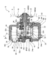
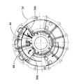
図1は、本発明の一実施形態としての潤滑構造を用いた電動機ユニット20を搭載するインホイールモータ10の構成の概略を示す構成図であり、図2は、図1のV−V断面を示す断面図である。
実施例のインホイールモータ10は、図1に示すように、電動機ユニット20と、この電動機ユニット20の出力軸2に取り付けられたハブ4と、このハブ4にボルトBにより固定されるホイール6に取り付けられる図示しないタイヤとを備える。
FIG. 1 is a configuration diagram showing an outline of a configuration of an in-
As shown in FIG. 1, the in-
実施例の電動機ユニット20は、図1に示すように、主として、電動機MGと、出力軸2と、電動機MGのロータシャフト22と出力軸2とを接続するプラネタリギヤ60とから構成されており、これらはケース30に収容されている。
ケース30は、電動機MGおよびプラネタリギヤ60を収容する第1ケース32と、ロータシャフト22をベアリングBRG1を介して回転可能に支持する第2ケース34と、出力軸2をベアリングBRG2を介して回転可能に支持する第3ケース36とがボルト38等の締結部品によって結合されて構成されている。
また、ケース30には、電動機MGやプラネタリギヤ60,各ベアリングBRG1,BRG2などの潤滑を行なうための潤滑油が充填されている。
As shown in FIG. 1, the
The case 30 includes a
The case 30 is filled with lubricating oil for lubricating the electric motor MG, the
なお、第2ケース34には、開口34aを塞ぐためのカバー部材40がボルト42によって結合され、第2ケース34にカバー部材40を取り付けることにより、図1および図2に示すように、第2ケース34の面と共に潤滑油を導入可能な導入口44を形成するとともに、導入された潤滑油を溜めることができるオイル貯留部46を形成する。
第2ケース34には、図2に示すように、飛散した潤滑油を導入口44に導くためのガイド壁34bが導入口44から外方に向かって放射状に形成されている。
A
In the
電動機MGは、ロータシャフト22と、このロータシャフト22にボルト22aによって取り付けられるとともに永久磁石が貼り付けられたロータ24と、三相コイルが巻回されたステータ26とを備える同期発電電動機として構成されており、ロータ24の内周面には、ケース30に充填された潤滑油を掻き上げることができる掻き上げリング50が圧入によって取り付けられている。
The electric motor MG is configured as a synchronous generator motor including a
電動機MGのロータシャフト22は、中空構造となっており、軸中心に潤滑油の潤滑油路22bを形成している。この潤滑油路22bには、電動機ユニット20の各部、例えば、プラネタリギヤ60やニードルベアリングNBRGに潤滑油を供給するための供給口として複数箇所に亘って径方向貫通孔22cが形成されている。なお、潤滑油路22bへは、オイル貯留部46からオイルチャネルOCを用いて潤滑油が供給される。
The
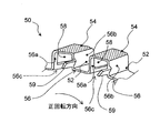
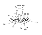
図3は、掻き上げリング50の構成を示す斜視図であり、図4は、掻き上げリング50が取り付けられたロータ24を拡大して示す拡大図であり、図5は、掻き上げリング50が取り付けられたロータ24を正面から見た正面図であり、図6は、図4のX−X断面を示す断面図である。
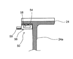
掻き上げリング50は、図3に示すように、凹部52と凸部54とが交互に形成されたリング状に形成されており、図3,図4および図5に示すように、凸部54の最外周面がロータ24の内周面に圧入されることによって凹部52が中空部を成す複数の掻き上げ歯56が形成される。なお、凹部52による中空部は、掻き上げリング50がロータ24内周面に取り付けられたときに、凹部52の長手方向一端側はロータ24のフランジ部24aによって塞がれるとともに、凹部52のフランジ部24aとは反対側である長手方向他端側は開口部56cとして開口された袋小路状となる。
3 is a perspective view showing a configuration of the
As shown in FIG. 3, the scraping
掻き上げ歯56の歯筋方向に沿う歯側面のうちロータ24の正回転方向(図3ないし図5における矢印方向)に対して前側となる前側歯側面56aには、図3ないし図6に示すように、中空部としての凹部52内外を連通する連通開口58が形成されている。ここで、連通開口58は、実施例では全ての掻き上げ歯56の前側歯側面56aに形成するものとした。
また、掻き上げ歯56の歯筋方向に沿う歯側面のうちロータ24の正回転方向に対して後側となる後側歯側面56bには、開口部56cからフランジ部24aとは反対方向に突出するガイド部59が連続して一体に設けられている。ここで、ガイド部59は、実施例では全ての掻き上げ歯56に対して形成するものとした。このガイド部59は、掻き上げリング50がロータ24内周面に取り付けられたときに、導入口44やオイル貯留部46の方向を向くように設定されている。
なお、掻き上げリング50の掻き上げ歯56は、第2ケース34に取り付けた回転数センサ80によってロータ24の回転位置を検出するための検出歯としても用いられる。これにより、回転位置を検出するための検出歯を別途設ける必要がなくなり、部品点数の増加を抑制できる。また、図1に示すように、回転数センサ80をロータ24の内周面側に収容できるから、インホイールモータ10自体をコンパクト化できる。
Of the tooth side surfaces along the tooth trace direction of the scraped
Further, among the tooth side surfaces along the tooth trace direction of the scraped
The scraping
プラネタリギヤ60は、図1に示すように、外歯歯車としてのサンギヤ62と、このサンギヤ62と同心円上に配置された内歯歯車としてのリングギヤ64と、サンギヤ62に噛合するとともにリングギヤ64に噛合する複数のピニオンギヤ66と、複数のピニオンギヤ66を自転かつ公転自在に保持するキャリア68とを備え、サンギヤ62とリングギヤ64とキャリア68とを回転要素として差動作用を行なう遊星歯車機構として構成されている。プラネタリギヤ60は、サンギヤ60がロータシャフト22に一体形成され、キャリア66が出力軸2に一体形成され、リングギヤ62が第1ケース32にその回転が禁止されるよう支持されている。
As shown in FIG. 1,
次に、こうして構成された電動機ユニット20の動作、特にロータ24の回転に伴う潤滑油掻き上げの際の動作について説明する。
インホイールモータ10が作動して電動機ユニット20の電動機MGが駆動すると、これに伴ってロータ24が回転する。これにより、ケース30に充填されている潤滑油はロータ24の内周面に取り付けられた掻き上げリング50の掻き上げ歯56によって掻き上げられる。このとき、掻き上げ歯56は内部が中空に形成されているとともに、ロータ24の正回転方向に対して前側となる前側歯側面56aに連通開口58が形成されているから、潤滑油が連通開口58を介して掻き上げ歯56の中空部に流れ込む。ここで、ロータ24の正回転方向に対して後側となる後側歯側面は閉じた形状に形成されているから、連通開口58から流れ込む潤滑油を掻き上げ歯56内に確実に溜め込むことができる。
このように、掻き上げリング50は、掻き上げ歯56内に潤滑油を溜め込みながら潤滑油を掻き上げるから、より多くの潤滑油を掻き上げることができる。しかも、掻き上げ歯56を中空に形成するだけだから、潤滑油を掻き上げる際のフリクション増加を抑えながら潤滑油を効率良く掻き上げることができる。また、掻き上げ歯56内に潤滑油を溜め込んだ分だけケース30に貯留される潤滑油の液面を下げることができるから、電動機MGの攪拌抵抗を小さくすることができる。
Next, the operation of the
When the in-
In this manner, the scraping
こうして掻き上げ歯56で掻き上げられた潤滑油は、一部は飛散により直接電動機MGやプラネタリギヤ60などの電動機ユニット20の各部の潤滑や冷却を行い、残りは直接あるいは図2の矢印で示すように第2ケース34のガイド壁34を伝って導入口44からオイル貯留部46に導入され、オイルチャネルOCやロータシャフト22の潤滑油路22b,径方向貫通孔22cなどを介してプラネタリギヤ60やニードルベアリングNBRGなどの電動機ユニット20の各部の潤滑や冷却を行う。
一方、掻き上げ歯56内に溜め込まれた潤滑油は、ロータ24の回転に伴い開口部56cから排出され、ガイド部59によって導入口44の方向に誘導される。そして、導入口44からオイル貯留部46に導入されてオイルチャネルOCやロータシャフト22の潤滑油路22b,径方向貫通孔22cなどを介してプラネタリギヤ60やニードルベアリングNBRGなどの電動機ユニット20の各部の潤滑や冷却を行う。
このように、より多くの潤滑油を掻き上げて電動機ユニット20の各部の潤滑や冷却を行うことができるから、潤滑性能の向上を図ることができる。しかも、ガイド部59により開口部56cから排出する潤滑油を確実に導入口44に誘導することができる。
A part of the lubricating oil thus swung up by the scooping
On the other hand, the lubricating oil accumulated in the scraping
Thus, since more lubricating oil can be scraped up and each part of the
以上説明した第1実施例の潤滑構造によれば、潤滑油を掻き上げる掻き上げリング50の掻き上げ歯56を中空に形成するから、ロータ24の回転に伴う潤滑油掻き上げの際に、掻き上げ歯56内に潤滑油を溜め込みながら潤滑油を掻き上げることができる。この結果、より多くの潤滑油を掻き上げることができる。しかも、掻き上げ歯56を中空に形成するだけだから、潤滑油を掻き上げる際のフリクション増加を抑えながら潤滑油を効率良く掻き上げることができる。また、掻き上げ歯56内に潤滑油を溜め込んだ分だけケース30に貯留される潤滑油の液面を下げることができるから、電動機MGの攪拌抵抗を小さくすることができる。
According to the lubricating structure of the first embodiment described above, the scraping
また、第1実施例の潤滑構造によれば、掻き上げ歯56内に溜め込んだ潤滑油を開口部56cから排出する際にガイド部59によって導入口44の方向に誘導するから、潤滑油を効果的にオイル貯留部46へ導入して電動機ユニット20の各部へ供給することができる。この結果、潤滑性能が向上する。しかも、ガイド部59は、潤滑油が排出される開口部56c近傍に形成されるから、潤滑油のガイドを確実に行うことができる。
Further, according to the lubricating structure of the first embodiment, when the lubricating oil accumulated in the scraping
さらに、第1実施例の潤滑構造によれば、凹部52と凸部54とが交互に形成された掻き上げリング50をロータ24の内周面に圧入するだけだから、より多くの潤滑油を掻き上げる構造を簡易に確保することができるとともに、電動機ユニット20の軸方向長さが増加するのを抑えてコンパクト化を図ることができる。
Furthermore, according to the lubricating structure of the first embodiment, only the
また、第1実施例の潤滑構造によれば、掻き上げリング50の掻き上げ歯56をロータ24の回転数を検出する検出歯としても用いるから、回転数検出歯を別途設ける必要がなく、部品点数の増加を抑制できる。
Further, according to the lubricating structure of the first embodiment, the scraping
第1実施例の潤滑構造では、掻き上げ歯56の前側歯側面56aに連通開口58を形成するものとしたが、連通開口58は形成しなくても差し支えない。この場合、開口部56cが、潤滑油の掻き上げ歯56内への流入口および排出口として用いられる。
In the lubricating structure of the first embodiment, the
第1実施例の潤滑構造では、開口部56cから排出される潤滑油を導入口44方向にガイドするガイド部59を設けるものとしたが、ガイド部59は設けなくても差し支えない。
In the lubricating structure of the first embodiment, the
次に、本発明の第2実施例としての潤滑構造を用いた電動機ユニット120を搭載するインホイールモータ100について説明する。
第2実施例の潤滑構造を用いた電動機ユニット120を搭載するインホイールモータ100は、掻き上げリング50を掻き上げリング150に変えた点を除いて図1および図2を用いて説明した第1実施例の潤滑構造を用いた電動機ユニット20を搭載するインホイールモータ10と同一の構成をしている。したがって、第2実施例のインホイールモータ100の構成のうち第1実施例のインホイールモータ10と同一の構成については同一の符号を付し、図示とその詳細な説明は、重複を避けるため省略する。
Next, the in-
The in-
図7は、掻き上げリング150が取り付けられたロータ124を拡大して示す拡大図であり、図8は、掻き上げリング150が取り付けられたロータ124を正面から見た正面図であり、図9は、図7のY−Y断面を示す断面図である。
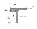
掻き上げリング150は、凹部152と凸部154とが交互に形成されたリング状に形成されており、図7および図8に示すように、凸部154の最外周面がロータ124の内周面に圧入されることによって凹部152が中空部を成す複数の掻き上げ歯156が形成される。凹部152による中空部は、掻き上げリング150をロータ124内周面に取り付けたときに、凹部152の長手方向両端面が閉塞される。
7 is an enlarged view showing the
The
掻き上げ歯156の歯筋方向に沿う歯側面のうちロータ124の正回転方向に対して前側となる前側歯側面156aには、図7ないし図9に示すように、中空部としての凹部152内外を連通する連通開口158が形成されている。また、凹部152による中空部を閉塞する凹部152の長手方向両端面のうちフランジ部124aとは反対方向側に形成された閉塞壁156cには、図示するように、連通開口158と比較して開口面積が小さいオリフィス156dが形成されている。ここで、連通開口158は、実施例では全ての掻き上げ歯156の前側歯側面156aに形成するものとし、オリフィス156dは、実施例では全ての掻き上げ歯156の閉塞壁156cに形成するものとした。
オリフィス156dは、図8に示すように、閉塞壁156cのうち径方向最外方付近であって前側歯側面156aに対向する面である後側歯側面156b寄りに形成されている。なお、後側歯側面156bとは、掻き上げ歯156の歯筋方向に沿う歯側面のうちロータ124の正回転方向に対して後側となる面である。また、掻き上げリング150の掻き上げ歯156は、ロータ124の回転位置を検出するための検出歯としても用いられる。
Among the tooth side surfaces along the tooth trace direction of the scraped
As shown in FIG. 8, the
次に、こうして構成された電動機ユニット120の動作、特にロータ124の回転に伴う潤滑油掻き上げの際の動作について説明する。
インホイールモータ100が作動して電動機ユニット120の電動機MGが駆動すると、これに伴ってロータ124が回転する。これにより、ケース30に充填されている潤滑油はロータ124の内周面に取り付けられた掻き上げリング150の掻き上げ歯156によって掻き上げられる。このとき、掻き上げ歯156は内部が中空に形成されているとともに、ロータ124の正回転方向に対して前側となる前側歯側面156aに連通開口158が形成されているから、潤滑油が連通開口158を介して掻き上げ歯156の中空部に流れ込む。ここで、ロータ124の正回転方向に対して後側となる後側歯側面156bは閉じた形状に形成されているから、連通開口158から流れ込む潤滑油を掻き上げ歯156内に確実に溜め込むことができる。
このように、掻き上げリング150は、掻き上げ歯156内に潤滑油を溜め込みながら潤滑油を掻き上げるから、より多くの潤滑油を掻き上げることができる。しかも、掻き上げ歯156を中空に形成するだけだから、潤滑油を掻き上げる際のフリクション増加を抑えながら潤滑油を効率良く掻き上げることができる。また、掻き上げ歯156内に潤滑油を溜め込んだ分だけケース30に貯留される潤滑油の液面を下げることができるから、電動機MGの攪拌抵抗を小さくすることができる。
Next, the operation of the
When the in-
In this way, the
こうして掻き上げ歯156で掻き上げられた潤滑油は、一部は飛散により直接電動機MGやプラネタリギヤ60などの電動機ユニット120の各部の潤滑や冷却を行い、残りは直接あるいは第2ケース34のガイド壁34を伝って導入口44からオイル貯留部46に導入され、オイルチャネルOCやロータシャフト22の潤滑油路22b,径方向貫通孔22cなどを介してプラネタリギヤ60やニードルベアリングNBRGなどの電動機ユニット120の各部の潤滑や冷却を行う。一方、掻き上げ歯156内に溜め込まれた潤滑油は、ロータ124の回転に伴いオリフィス156dから導入口44の方向に向かって排出される。ここで、オリフィス156dは、連通開口158よりも開口面積が小さく形成されているから、掻き上げ歯156内の潤滑油は排出され難いものとなっている。
これにより、掻き上げ歯156内に溜め込まれた潤滑油をより長い間保持することができ、比較的高い位置に形成された導入口44の高さまで潤滑油を運搬できる。また、閉塞壁156cのうち径方向最外方付近であって後側歯側面156b寄りの位置、即ち、ロータ24の回転に伴う遠心力と回転力とにより掻き上げ歯156内の潤滑油に最も圧力が作用する位置にオリフィス156dを形成するから、オリフィス156dから勢い良く潤滑油を排出することができる。この結果、導入口44への潤滑油供給をより確実なものとすることができる。
A part of the lubricating oil thus scraped up by the scraping
Thereby, the lubricating oil accumulated in the scraping
そして、導入口44に供給された潤滑油は、オイル貯留部46に導入されてオイルチャネルOCやロータシャフト22の潤滑油路22b,径方向貫通孔22cなどを介してプラネタリギヤ60やニードルベアリングNBRGなどの電動機ユニット120の各部の潤滑や冷却を行う。このように、より多くの潤滑油を掻き上げて電動機ユニット120の各部の潤滑や冷却を行うことができるから、潤滑性能の向上を図ることができる。
Then, the lubricating oil supplied to the
以上説明した第2実施例の潤滑構造によれば、潤滑油を掻き上げる掻き上げリング150の掻き上げ歯156を中空に形成するから、ロータ124の回転に伴う潤滑油掻き上げの際に、掻き上げ歯156内に潤滑油を溜め込みながら潤滑油を掻き上げることができる。この結果、より多くの潤滑油を掻き上げることができる。しかも、掻き上げ歯156を中空に形成するだけだから、潤滑油を掻き上げる際のフリクション増加を抑えながら潤滑油を効率良く掻き上げることができる。また、掻き上げ歯156内に潤滑油を溜め込んだ分だけケース30に貯留される潤滑油の液面を下げることができるから、電動機MGの攪拌抵抗を小さくすることができる。
According to the lubricating structure of the second embodiment described above, the scraping
また、第2実施例の潤滑構造によれば、掻き上げ歯156内の潤滑油の出口としてのオリフィス159を、掻き上げ歯156内への潤滑油の入口としての導入開口158に比較して開口面積を小さくして、掻き上げ歯156内の潤滑油を排出し難いものとしたから、掻き上げ歯156内に溜め込まれた潤滑油をより長い間保持することができ、比較的高い位置に形成された導入口44の高さまで運搬できる。しかも、オリフィス156dを閉塞壁156cのうち径方向最外方付近であって後側歯側面156b寄りに形成するから、掻き上げ歯156内の潤滑油を、ロータ24の回転に伴う遠心力と回転力とにより最も圧力が作用する位置から排出することができ、オリフィス156dから勢い良く潤滑油を排出することができる。この結果、導入口44への潤滑油供給をより確実なものとすることができる。
Further, according to the lubricating structure of the second embodiment, the orifice 159 serving as the lubricant outlet in the scraping
さらに、第2実施例の潤滑構造によれば、凹部152と凸部154とが交互に形成された掻き上げリング150をロータ124の内周面に圧入するだけだから、より多くの潤滑油を掻き上げる構造を簡易に確保することができると共に、電動機ユニット120の軸方向長さが増加するのを抑えてコンパクト化を図ることができる。
Furthermore, according to the lubricating structure of the second embodiment, only the
また、第2実施例の潤滑構造によれば、掻き上げリング150の掻き上げ歯156をロータ124の回転数を検出する検出歯としても用いるから、回転数検出歯を別途設ける必要がなく、部品点数の増加を抑制できる。
Further, according to the lubricating structure of the second embodiment, the scraping
次に、本発明の第3実施例としての潤滑構造を用いた電動機ユニット220を搭載するインホイールモータ200について説明する。
第3実施例の潤滑構造を用いた電動機ユニット220を搭載するインホイールモータ200は、掻き上げリング50を掻き上げリング250に変えた点を除いて図1および図2を用いて説明した第1実施例の潤滑構造を用いた電動機ユニット20を搭載するインホイールモータ10と同一の構成をしている。したがって、第3実施例のインホイールモータ200の構成のうち第1実施例のインホイールモータ10と同一の構成については同一の符号を付し、図示とその詳細な説明は、重複を避けるため省略する。
Next, an in-
The in-
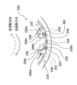
図10は、掻き上げリング250が取り付けられたロータ224を拡大して示す拡大図であり、図11は、掻き上げリング250が取り付けられたロータ224を正面から見た正面図であり、図12は、図10のZ−Z断面を示す断面図である。
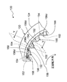
掻き上げリング250は、凹部252と凸部254とが交互に形成されたリング状に形成されており、図10および図11に示すように、凸部254の最外周面がロータ224の内周面に圧入されることによって凹部252が中空部を成す複数の掻き上げ歯256が形成される。凹部252による中空部は、掻き上げリング250をロータ224内周面に取り付けたときに、凹部252の長手方向両端面が閉塞される。
10 is an enlarged view showing the
The
掻き上げ歯256の歯筋方向に沿う歯側面のうちロータ224の正回転方向に対して前側となる前側歯側面256aには、図10ないし図12に示すように、中空部としての凹部252内外を連通する連通開口258が形成されている。また、凹部252による中空部を閉塞する凹部252の長手方向両端面のうちフランジ部224aとは反対方向側に形成された閉塞壁256cには、図示するように、連通開口258と比較して開口面積が小さい連通孔260を有するオイル排出パイプ259が取り付けられている。ここで、連通開口258は、実施例では全ての掻き上げ歯256の前側歯側面256aに形成するものとし、オイル排出パイプ259は、実施例では全ての掻き上げ歯256の閉塞壁256cに形成するものとした。
オイル排出パイプ259は、図11に示すように、閉塞壁256cのうち径方向最外方付近であって前側歯側面256aに対向する面である後側歯側面256b寄りの位置に配設されており、閉塞壁256cから導入口44やオイル貯留部46の方向を向くように突出するとともに掻き上げ歯256内に突出している。なお、後側歯側面256bとは、掻き上げ歯256の歯筋方向に沿う歯側面のうちロータ224の正回転方向に対して後側となる面である。また、掻き上げリング250の掻き上げ歯256は、ロータ224の回転位置を検出するための検出歯としても用いられる。
Of the tooth side surfaces along the tooth trace direction of the scraped
As shown in FIG. 11, the
次に、こうして構成された電動機ユニット220の動作、特にロータ224の回転に伴う潤滑油掻き上げの際の動作について説明する。
インホイールモータ200が作動して電動機ユニット220の電動機MGが駆動すると、これに伴ってロータ224が回転する。これにより、ケース30に充填されている潤滑油はロータ224の内周面に取り付けられた掻き上げリング250の掻き上げ歯256によって掻き上げられる。このとき、掻き上げ歯256は内部が中空に形成されているとともに、ロータ224の正回転方向に対して前側となる前側歯側面256aに連通開口258が形成されているから、潤滑油が連通開口258を介して掻き上げ歯256の中空部に流れ込む。ここで、ロータ224の正回転方向に対して後側となる後側歯側面256bは閉じた形状に形成されているから、連通開口258から流れ込む潤滑油を掻き上げ歯256内に確実に溜め込むことができる。
このように、掻き上げリング250は、掻き上げ歯256内に潤滑油を溜め込みながら潤滑油を掻き上げるから、より多くの潤滑油を掻き上げることができる。しかも、掻き上げ歯256を中空に形成するだけだから、潤滑油を掻き上げる際のフリクション増加を抑えながら潤滑油を効率良く掻き上げることができる。また、掻き上げ歯256内に潤滑油を溜め込んだ分だけケース30に貯留される潤滑油の液面を下げることができるから、電動機MGの攪拌抵抗を小さくすることができる。
Next, the operation of the
When the in-
In this way, the
こうして掻き上げ歯256で掻き上げられた潤滑油は、一部は飛散により直接電動機MGやプラネタリギヤ60などの電動機ユニット220の各部の潤滑や冷却を行い、残りは直接あるいは第2ケース34のガイド壁34を伝って導入口44からオイル貯留部46に導入され、オイルチャネルOCやロータシャフト22の潤滑油路22b,径方向貫通孔22cなどを介してプラネタリギヤ60やニードルベアリングNBRGなどの電動機ユニット220の各部の潤滑や冷却を行う。
一方、掻き上げ歯256内に溜め込まれた潤滑油は、ロータ224の回転に伴い排出パイプ259の連通孔260から導入口44の方向に向かって排出される。ここで、排出パイプ259は、連通孔260が連通開口258よりも開口面積が小さく所定長さを有するチョークとして形成されているから、掻き上げ歯156内の潤滑油は、閉塞壁256cに単に排出孔(オリフィス)を形成したものよりもより排出され難いものとなっている。これにより、掻き上げ歯256内に溜め込まれた潤滑油をより長い間保持することができ、比較的高い位置に形成された導入口44の高さまで潤滑油を運搬できる。また、閉塞壁256cのうち径方向最外方付近であって後側歯側面256b寄りの位置、即ち、ロータ224の回転に伴う遠心力と回転力とにより掻き上げ歯256内の潤滑油に最も圧力が作用する位置に排出パイプ259を配設するから、連通孔160から潤滑油を排出する際には勢い良く排出することができる。しかも、排出パイプ259は、閉塞壁256cから導入口44の方向に向かって突出しているから、導入口44へより確実に潤滑油を供給することができる。
A part of the lubricating oil thus swung up by the scooping
On the other hand, the lubricating oil accumulated in the scraping
そして、導入口44に供給された潤滑油は、オイル貯留部46に導入されてオイルチャネルOCやロータシャフト22の潤滑油路22b,径方向貫通孔22cなどを介してプラネタリギヤ60やニードルベアリングNBRGなどの電動機ユニット220の各部の潤滑や冷却を行う。このように、より多くの潤滑油を掻き上げて電動機ユニット220の各部の潤滑や冷却を行うことができるから、潤滑性能の向上を図ることができる。
Then, the lubricating oil supplied to the
以上説明した第3実施例の潤滑構造によれば、潤滑油を掻き上げる掻き上げリング250の掻き上げ歯256を中空に形成するから、ロータ224の回転に伴う潤滑油掻き上げの際に、掻き上げ歯256内に潤滑油を溜め込みながら潤滑油を掻き上げることができる。この結果、より多くの潤滑油を掻き上げることができる。しかも、掻き上げ歯256を中空に形成するだけだから、潤滑油を掻き上げる際のフリクション増加を抑えながら潤滑油を効率良く掻き上げることができる。また、掻き上げ歯256内に潤滑油を溜め込んだ分だけケース30に貯留される潤滑油の液面を下げることができるから、電動機MGの攪拌抵抗を小さくすることができる。
According to the lubricating structure of the third embodiment described above, the scraping
また、第3実施例の潤滑構造によれば、掻き上げ歯256内の潤滑油の出口を排出パイプを用いてチョークとするから、掻き上げ歯256内の潤滑油が閉塞壁256cに単に排出孔(オリフィス)を形成するものよりもより排出され難いものとなる。この結果、掻き上げ歯256内に溜め込まれた潤滑油をより長い間保持することができ、比較的高い位置に形成された導入口44の高さまで潤滑油を運搬できる。また、閉塞壁256cのうち径方向最外方付近であって後側歯側面256b寄りの位置、即ち、ロータ224の回転に伴う遠心力と回転力とにより掻き上げ歯256内の潤滑油に最も圧力が作用する位置に排出パイプ259を配設するから、連通孔160から潤滑油を排出する際には勢い良く排出することができる。しかも、排出パイプ259は、閉塞壁256cから導入口44の方向に向かって突出しているから、導入口44へより確実に潤滑油を供給することができる。この結果、潤滑性能が向上する。
Further, according to the lubricating structure of the third embodiment, the outlet of the lubricating oil in the scraping
さらに、第3実施例の潤滑構造によれば、凹部252と凸部254とが交互に形成された掻き上げリング250をロータ224の内周面に圧入するだけだから、より多くの潤滑油を掻き上げる構造を簡易に確保することができるとともに、電動機ユニット220の軸方向長さが増加するのを抑えてコンパクト化を図ることができる。
Furthermore, according to the lubricating structure of the third embodiment, only the
また、第3実施例の潤滑構造によれば、掻き上げリング250の掻き上げ歯256をロータ224の回転数を検出する検出歯としても用いるから、回転数検出歯を別途設ける必要がなく、部品点数の増加を抑制できる。
Further, according to the lubricating structure of the third embodiment, the scraping
第1実施例や第2実施例,第3実施例の潤滑構造では、連通開口58,158,258は、全ての掻き上げ歯56,156,256の前側歯側面56a,156a,256aに形成するものとしたが、全ての掻き上げ歯56,156,256の前側歯側面56a,156a,256aに形成する必要はなく、例えば、一つの掻き上げ歯56,156,256の前側歯側面56a,156a,256aだけに形成するものとしたり、一つおきの掻き上げ歯56,156,256の前側歯側面56a,156a,256aに形成するものとしても構わない。
In the lubricating structures of the first embodiment, the second embodiment, and the third embodiment, the
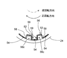
第1実施例や第2実施例,第3実施例の潤滑構造では、連通開口58,158,258は、前側歯側面56a,156a,256aにのみ形成するものとしたが、ある掻き上げ歯56,156,256には、連通開口58,158,258は前側歯側面56a,156a,256aに形成し、他の掻き上げ歯56,156,256には、連通開口58,158,258は後側歯側面56b,156b,256bに形成するものとしても構わない。こうすれば、ロータ24,124,224が正回転するときだけでなく、逆回転するときにも潤滑油を掻き上げ歯56,156,256内の中空部に溜め込むことができる。この場合、図13,図14および図15の変形例の潤滑構造に例示するように、連通開口58,158,258は前側歯側面56a,156a,256aと後側歯側面56b,156b,256bとに交互に設けるものとしても良い。このとき、ガイド部59やオリフィス156d,オイル排出パイプ259の形状や配置位置は、連通開口58,158,258に対応して変えるものとすれば良い。こうすれば、ロータ24,124,224が正回転するときと逆回転するときとでほぼ同等の潤滑性能を得ることができる。
In the lubricating structures of the first embodiment, the second embodiment, and the third embodiment, the
第1実施例や第2実施例,第3実施例の潤滑構造では、掻き上げリング50,150,250をロータ24,124,224の内周面に圧入によって取り付けるものとしたが、溶接やボルト締結など、取り付け方は如何なるものであっても構わない。
In the lubricating structures of the first embodiment, the second embodiment, and the third embodiment, the scraping rings 50, 150, 250 are attached to the inner peripheral surfaces of the
第1実施例や第2実施例,第3実施例の潤滑構造では、掻き上げリング50,150,250をロータ24,124,224の内周面に圧入によって取り付けることにより掻き上げ歯56,156,256を形成するものとしたが、掻き上げ歯56,156,256はロータ24,124,224の内周面に一体形成するものであっても構わない。
In the lubricating structures of the first embodiment, the second embodiment, and the third embodiment, the scraping
第2実施例や第3実施例では、オリフィス156dおよびオイル排出パイプ259は、閉塞壁156c,256cのうち後側歯側面156b,256b寄りに形成するものとしたが、オリフィス156dおよびオイル排出パイプ259は、閉塞壁156c,256cのうち前側歯側面156a,256a寄りに形成するものとしたり、前側歯側面156a,256aと後側歯側面156b,256bとの間のほぼ中央部に形成するものしても差し支えない。
In the second and third embodiments, the
第2実施例や第3実施例では、オリフィス156dおよびオイル排出パイプ259は、閉塞壁156c,256cのうち径方向最外方付近に形成するものとしたが、オリフィス156dおよびオイル排出パイプ259は、閉塞壁156c,256cのうち径方向最内方付近に形成するものとしたり、径方向最内方付近と径方向最外方付近との間のほぼ中央部に形成するものしても差し支えない。
In the second and third embodiments, the
以上、本発明の実施の形態について実施例を用いて説明したが、本発明はこうした実施例に限定されるものではなく、本発明の要旨を逸脱しない範囲内において、種々なる形態で実施し得ることは勿論である。 As mentioned above, although embodiment of this invention was described using the Example, this invention is not limited to such an Example, In the range which does not deviate from the summary of this invention, it can implement with a various form. Of course.
2 出力軸
10,100,200 インホイールモータ
20,120,220 電動機ユニット
22 ロータシャフト
22a ボルト
22b 潤滑油路
22c 貫通孔
24,124,224 ロータ
24a,124a,224a フランジ部
26 ステータ
30 ケース
32 第1ケース
34 第2ケース
34a 開口
34b ガイド壁
36 第3ケース
38 ボルト
40 カバー部材
42 ボルト
44 導入口
46 オイル貯留部
50,150,250 掻き上げリング
52,152,252 凹部
54,154,254 凸部
56,156,256 掻き上げ歯
56a,156a,256a 前側歯側面
56b,156b,256b 後側歯側面
56c 開口部
58,158,258 連通開口
59 ガイド部
60 プラネタリギヤ
62 サンギヤ
64 リングギヤ
66 ピニオンギヤ
68 キャリア
80 回転数センサ
156c,256c 閉塞壁
156d オリフィス
259 オイル排出パイプ
260 連通孔
MG 電動機
BRG1 ベアリング
BRG2 ベアリング
OC オイルチャネル
NBRG ニードルベアリング
2
Claims (18)
前記掻き上げ部材は、少なくとも前記潤滑油を掻き上げる掻き上げ部が中空に形成されてなり、中空に形成された該掻き上げ部内へ前記潤滑油を導入可能な導入開口が形成されてなる
潤滑構造。 A scraping member capable of scooping up the lubricating oil with the rotation of the rotating shaft is provided, and at least a part of each part of the power mechanism is lubricated directly or indirectly using the lubricating oil scraped up by the scraping member. A lubrication structure,
Lubrication structure in which the scraping member is formed such that at least the scraping portion for scraping the lubricating oil is formed in a hollow, and an introduction opening through which the lubricating oil can be introduced into the scraping portion formed in a hollow is formed .
前記導入開口は、歯筋方向に沿う歯側面に形成されてなる請求項1または2記載の潤滑構造。 The scraping part is formed in a tooth shape,
The lubricating structure according to claim 1, wherein the introduction opening is formed on a tooth side surface along a tooth trace direction.
前記導入開口は、前記第1掻き上げ部においては前記前側は側面に形成されてなり、前記第2掻き上げ部においては前記歯側面のうち前記掻き上げ部材の回転方向後側となる後側歯側面に形成されてなる請求項4記載の潤滑構造。 The scraping member has a first scraping portion and a second scraping portion in the circumferential direction as the scraping portion,
The introduction opening is formed on the side surface on the front side in the first scraping portion, and on the second scraping portion, a rear tooth that is the rear side in the rotation direction of the scraping member among the tooth side surfaces. The lubricating structure according to claim 4, wherein the lubricating structure is formed on a side surface.
前記ロータの内周面に前記掻き上げ部材を配置し、請求項1ないし13いずれか記載の潤滑構造を用いて各部の少なくとも一部を潤滑する
電動機ユニット。 An electric motor unit as the power mechanism including an electric motor having a rotor shaft as the rotating shaft and a rotor that rotates integrally with the rotor shaft,
The electric motor unit which arrange | positions the said scraping member on the internal peripheral surface of the said rotor, and lubricates at least one part of each part using the lubrication structure in any one of Claim 1 thru | or 13.
前記ロータシャフトは、前記潤滑油の流路としての潤滑油路が軸中心に形成されるとともに前記潤滑油の供給口としての貫通孔が前記潤滑油路から径方向に貫通して形成され、前記貯留部から前記潤滑油路に供給された潤滑油を回転により前記貫通孔から各部へ供給してなる
請求項14ないし16いずれか記載の電動機ユニット。 An electric motor case that houses the electric motor and forms a storage portion that stores the lubricating oil scraped up together with other members;
In the rotor shaft, a lubricating oil passage as a flow passage for the lubricating oil is formed in the center of the shaft, and a through hole as a supply port for the lubricating oil is formed to penetrate from the lubricating oil passage in a radial direction, The electric motor unit according to any one of claims 14 to 16, wherein the lubricating oil supplied from the reservoir to the lubricating oil passage is supplied to each part from the through hole by rotation.
前記電動機ユニットは、前記電動機からの動力を減速して前記駆動輪に出力する遊星歯車機構を有し、
該遊星歯車機構の3つの回転要素のうちの2つの回転要素に前記ロータシャフトと前記駆動輪に接続された出力軸とをそれぞれ接続し、
他の1つの回転要素を前記電動機ユニットのケースに回転不能に支持してなる
インホイールモータ。 An in-wheel motor that drives a drive wheel by arranging the electric motor unit according to any one of claims 14 to 17 in a wheel,
The electric motor unit has a planetary gear mechanism that decelerates the power from the electric motor and outputs it to the drive wheels.
Connecting the rotor shaft and the output shaft connected to the drive wheel to two of the three rotating elements of the planetary gear mechanism,
An in-wheel motor in which another rotating element is non-rotatably supported by the case of the electric motor unit.
Priority Applications (1)
| Application Number | Priority Date | Filing Date | Title |
|---|---|---|---|
| JP2008225206A JP5210094B2 (en) | 2008-09-02 | 2008-09-02 | Lubrication structure, electric motor unit and in-wheel motor |
Applications Claiming Priority (1)
| Application Number | Priority Date | Filing Date | Title |
|---|---|---|---|
| JP2008225206A JP5210094B2 (en) | 2008-09-02 | 2008-09-02 | Lubrication structure, electric motor unit and in-wheel motor |
Publications (2)
| Publication Number | Publication Date |
|---|---|
| JP2010060026A true JP2010060026A (en) | 2010-03-18 |
| JP5210094B2 JP5210094B2 (en) | 2013-06-12 |
Family
ID=42187052
Family Applications (1)
| Application Number | Title | Priority Date | Filing Date |
|---|---|---|---|
| JP2008225206A Active JP5210094B2 (en) | 2008-09-02 | 2008-09-02 | Lubrication structure, electric motor unit and in-wheel motor |
Country Status (1)
| Country | Link |
|---|---|
| JP (1) | JP5210094B2 (en) |
Cited By (5)
| Publication number | Priority date | Publication date | Assignee | Title |
|---|---|---|---|---|
| WO2012098957A1 (en) * | 2011-01-21 | 2012-07-26 | Ntn株式会社 | In-wheel motor drive device |
| JP2012240664A (en) * | 2011-05-23 | 2012-12-10 | Hyundai Mobis Co Ltd | In-wheel driving device |
| US8678115B2 (en) | 2010-08-06 | 2014-03-25 | Aisin Aw Co., Ltd. | Vehicle drive device |
| JP2014059044A (en) * | 2012-09-19 | 2014-04-03 | Aisin Aw Co Ltd | Driving device |
| US20160218595A1 (en) * | 2015-01-28 | 2016-07-28 | Denso Corporation | Rotating electrical machine |
Citations (4)
| Publication number | Priority date | Publication date | Assignee | Title |
|---|---|---|---|---|
| JPS6184263U (en) * | 1984-11-06 | 1986-06-03 | ||
| JPH0616761U (en) * | 1992-08-06 | 1994-03-04 | 栃木富士産業株式会社 | Lubrication device for power transmission device |
| JP2001173762A (en) * | 1999-10-05 | 2001-06-26 | Aisin Aw Co Ltd | Lubrication device for drive unit |
| JP2003042273A (en) * | 2001-07-26 | 2003-02-13 | Aisin Ai Co Ltd | Lubricating device for transmission |
-
2008
- 2008-09-02 JP JP2008225206A patent/JP5210094B2/en active Active
Patent Citations (4)
| Publication number | Priority date | Publication date | Assignee | Title |
|---|---|---|---|---|
| JPS6184263U (en) * | 1984-11-06 | 1986-06-03 | ||
| JPH0616761U (en) * | 1992-08-06 | 1994-03-04 | 栃木富士産業株式会社 | Lubrication device for power transmission device |
| JP2001173762A (en) * | 1999-10-05 | 2001-06-26 | Aisin Aw Co Ltd | Lubrication device for drive unit |
| JP2003042273A (en) * | 2001-07-26 | 2003-02-13 | Aisin Ai Co Ltd | Lubricating device for transmission |
Cited By (9)
| Publication number | Priority date | Publication date | Assignee | Title |
|---|---|---|---|---|
| US8678115B2 (en) | 2010-08-06 | 2014-03-25 | Aisin Aw Co., Ltd. | Vehicle drive device |
| WO2012098957A1 (en) * | 2011-01-21 | 2012-07-26 | Ntn株式会社 | In-wheel motor drive device |
| CN103328247A (en) * | 2011-01-21 | 2013-09-25 | Ntn株式会社 | In-wheel motor drive device |
| US9180771B2 (en) | 2011-01-21 | 2015-11-10 | Ntn Corporation | In-wheel motor drive device |
| JP2012240664A (en) * | 2011-05-23 | 2012-12-10 | Hyundai Mobis Co Ltd | In-wheel driving device |
| JP2014059044A (en) * | 2012-09-19 | 2014-04-03 | Aisin Aw Co Ltd | Driving device |
| US20160218595A1 (en) * | 2015-01-28 | 2016-07-28 | Denso Corporation | Rotating electrical machine |
| JP2016140194A (en) * | 2015-01-28 | 2016-08-04 | 株式会社デンソー | Rotary electric machine |
| US10116189B2 (en) * | 2015-01-28 | 2018-10-30 | Denso Corporation | Rotating electrical machine equipped with rotor with oil containers |
Also Published As
| Publication number | Publication date |
|---|---|
| JP5210094B2 (en) | 2013-06-12 |
Similar Documents
| Publication | Publication Date | Title |
|---|---|---|
| JP6137317B2 (en) | Drive transmission device | |
| JP5210094B2 (en) | Lubrication structure, electric motor unit and in-wheel motor | |
| JP5075875B2 (en) | Dump truck traveling device | |
| JP2011236950A (en) | Swiveling device for construction machinery | |
| US9851001B2 (en) | Drive unit for vehicles | |
| JP2018048679A (en) | Gear device | |
| JP2018105419A (en) | Lubrication structure of hybrid vehicle | |
| US20120217825A1 (en) | Vehicle drive system | |
| JP2012138989A (en) | Power transmission apparatus | |
| JP5806133B2 (en) | In-wheel motor drive device | |
| JP2015132315A (en) | Oil feed structure of motor drive unit | |
| JP4701587B2 (en) | Electric drive | |
| JP2011021656A (en) | Lubricating structure of differential device | |
| JP6244772B2 (en) | Hybrid vehicle drive device | |
| JP4867521B2 (en) | Electric drive | |
| JP2012077848A (en) | Lubricating structure of compound planetary gear device | |
| JP5141699B2 (en) | Lubricating oil supply device | |
| JP2011196530A (en) | Lubricating oil circulation structure for transmission | |
| JP2007028700A (en) | Rotary electric machine | |
| JP2020190314A (en) | Transmission | |
| JP7380903B2 (en) | Vehicle drive system | |
| JP2003120894A (en) | Bearing lubrication structure of rotary shaft | |
| JP5251451B2 (en) | Electric drive | |
| JP2013060976A (en) | Lubrication structure of final reduction gear | |
| JP6645216B2 (en) | Lubricating oil supply device |
Legal Events
| Date | Code | Title | Description |
|---|---|---|---|
| A621 | Written request for application examination |
Free format text: JAPANESE INTERMEDIATE CODE: A621 Effective date: 20110615 |
|
| A977 | Report on retrieval |
Free format text: JAPANESE INTERMEDIATE CODE: A971007 Effective date: 20120822 |
|
| A131 | Notification of reasons for refusal |
Free format text: JAPANESE INTERMEDIATE CODE: A131 Effective date: 20120904 |
|
| A521 | Written amendment |
Free format text: JAPANESE INTERMEDIATE CODE: A523 Effective date: 20121024 |
|
| TRDD | Decision of grant or rejection written | ||
| A01 | Written decision to grant a patent or to grant a registration (utility model) |
Free format text: JAPANESE INTERMEDIATE CODE: A01 Effective date: 20130219 |
|
| A61 | First payment of annual fees (during grant procedure) |
Free format text: JAPANESE INTERMEDIATE CODE: A61 Effective date: 20130222 |
|
| FPAY | Renewal fee payment (event date is renewal date of database) |
Free format text: PAYMENT UNTIL: 20160301 Year of fee payment: 3 |
|
| R150 | Certificate of patent or registration of utility model |
Ref document number: 5210094 Country of ref document: JP Free format text: JAPANESE INTERMEDIATE CODE: R150 Free format text: JAPANESE INTERMEDIATE CODE: R150 |
|
| S111 | Request for change of ownership or part of ownership |
Free format text: JAPANESE INTERMEDIATE CODE: R313117 |
|
| R350 | Written notification of registration of transfer |
Free format text: JAPANESE INTERMEDIATE CODE: R350 |