JP2010059593A - Foldable cap - Google Patents

Foldable cap Download PDF

Info

Publication number
JP2010059593A
JP2010059593A JP2008236181A JP2008236181A JP2010059593A JP 2010059593 A JP2010059593 A JP 2010059593A JP 2008236181 A JP2008236181 A JP 2008236181A JP 2008236181 A JP2008236181 A JP 2008236181A JP 2010059593 A JP2010059593 A JP 2010059593A
Authority
JP
Japan
Prior art keywords
flat plate
state
main body
foldable
hat
Prior art date
Legal status (The legal status is an assumption and is not a legal conclusion. Google has not performed a legal analysis and makes no representation as to the accuracy of the status listed.)
Granted
Application number
JP2008236181A
Other languages
Japanese (ja)
Other versions
JP5185034B2 (en
Inventor
Norikatsu Morita
法勝 森田
Keiichi Hirata
敬一 平田
Current Assignee (The listed assignees may be inaccurate. Google has not performed a legal analysis and makes no representation or warranty as to the accuracy of the list.)
YELLOW KK
Yellow KK
Original Assignee
YELLOW KK
Yellow KK
Priority date (The priority date is an assumption and is not a legal conclusion. Google has not performed a legal analysis and makes no representation as to the accuracy of the date listed.)
Filing date
Publication date
Application filed by YELLOW KK, Yellow KK filed Critical YELLOW KK
Priority to JP2008236181A priority Critical patent/JP5185034B2/en
Publication of JP2010059593A publication Critical patent/JP2010059593A/en
Application granted granted Critical
Publication of JP5185034B2 publication Critical patent/JP5185034B2/en
Active legal-status Critical Current
Anticipated expiration legal-status Critical

Links

Images

Landscapes

  • Helmets And Other Head Coverings (AREA)

Abstract

<P>PROBLEM TO BE SOLVED: To provide a foldable cap for quickly protecting the head in an emergency and disaster by securely functioning a means for retaining spread state with easy operation and a little force. <P>SOLUTION: A body 10A of the foldable cap includes the means for retaining spread state wherein the foldable cap is spread by mutually approaching folding inclination parts 15b and 15c of a connecting part 15 and by deforming a front flat plate 12 and a rear flat plate 13 from a flat state against elasticity. The means for retaining a spread state is provided with an engaging part 21 which is arranged outside the folding inclination parts 15b and 15c, and an engaged part 22 which is engaged with and disengaged from the engaging part 21. One end of a fastening string 23 is connected to the engaging part 21 and extended inside by passing through the folding inclination parts 15b and 15c. An end of a chin strap 24 is connected to the engaging part 21. When the chin strap 24 is pulled, the engaging part 21 is engaged with the engaged part 22 so as to retain the spread state. <P>COPYRIGHT: (C)2010,JPO&INPIT

Description

この発明は、平板状態で形状が安定する平板を備えた折畳み式帽子に関する。   The present invention relates to a folding hat provided with a flat plate whose shape is stable in a flat plate state.

従来、不使用時、携帯時又は物流の際に嵩張らないようにするために折畳み式にされた帽子としては、特許文献1に記載されているものがあった。   Conventionally, there is a cap described in Patent Document 1 as a foldable hat so as not to be bulky when not in use, when being carried, or when being distributed.

特許文献1には、「一枚の薄板体(1)の中央部分に頭が入る大きさの開口部を設け、開口部の両側に開口部から少し離れた位置に湾曲した曲線状折り目(3)をつけ、該薄板体(1)を開口部の中心部を横切る中心折り目(2)で二つ折りにし、重なった端部の糊代(6)の部分を接合し、そうした後、両側の、湾曲した曲線状折り目(3)の部分をそとに張り出すように折り曲げて、二つ折りにされた中心折り目(2)を伸展することにより立体形状の構造体とし、開口部を頭に被せることにより帽子としての働きをする折り畳み式帽子」が記載されている。
実開平7−43450号公報
In Patent Document 1, “a curved fold line (3 is provided with an opening having a size that allows the head to enter the central portion of one thin plate (1), and curved slightly away from the opening on both sides of the opening. ), And the sheet (1) is folded in half at the center crease (2) across the center of the opening, and the overlapping margin portions (6) are joined. Bending the curved curved crease (3) so that it overhangs, extending the center crease (2) folded in half to make a three-dimensional structure, and covering the opening on the head Describes a foldable hat that acts as a hat.
Japanese Utility Model Publication No. 7-43450

しかしながら、特許文献1に記載された発明は、一枚の薄板体の中央部分に設けられた頭が入る大きさの開口部から少し離れた位置に湾曲した曲線状折り目をつけ、この曲線状折り目を折ることにより展開状態(着用可能状態)に保形する構成にされていたために、展開状態に保形されているときにあって、曲線状折り目を非折り状態にする外力、或いはそれよりも大きい外力を受けたときには、前記曲線状折り目が、前記展開状態(着用可能状態)を維持する保形機能を失した状態を起し易いものであった。したがって、平板状態で形状が安定する弾性平板で構成される折畳み式帽子の提供には構造的に不適当であるのみならず、一枚の薄板体(1)製であるので、他のものとの接触や衝突で変形や破損を惹起し易く、危険を避けるのには向いていない。   However, the invention described in Patent Document 1 has a curved crease that is curved at a position slightly away from an opening of a size provided in the central portion of one thin plate body, and the curved crease. Since it was configured to retain its shape in the unfolded state (wearable state) by folding, the external force to keep the curved fold in the unfolded state when it is retained in the unfolded state, or more When receiving a large external force, the curved fold line is likely to cause a state in which the shape retaining function for maintaining the unfolded state (wearable state) is lost. Therefore, it is not only structurally unsuitable for providing a foldable cap composed of an elastic flat plate whose shape is stable in a flat plate state, but it is made of one thin plate body (1). It is easy to cause deformation and breakage due to contact and collision, and is not suitable for avoiding danger.

一方、弾性を有する前側平板と弾性を有する後側平板とが連結部で連結された折畳み式帽子本体部を有する折畳み式帽子において、前側平板と後側平板とが弾性力により平板状態となって扁平状態になる一方、連結部の両側頭に対面する個所を互いに接近させて前側平板と後側平板とを弾性力に抗して湾曲状態として展開状態とし、展開状態を保持する展開状態保持手段を備えた構成とすることも考えられる。この構成の場合、折畳み式帽子の使用者は連結部の両側頭に対面する箇所を互いの連結部を接近させる方向に両手で押圧して展開状態保持手段を機能させ、展開状態を保持させる。しかし、この構成では連結部を両手で押圧して展開状態保持手段を機能させる際に大きな力が必要となり、迅速に使用を開始することが困難であったり、筋力の弱い子供、女性、老人等が使用しずらくなるという問題がある。また、突然の大地震等の緊急災害時には、落下物等から頭を守るためにできるだけ速く折畳み式帽子を頭部にかぶる必要がある。しかし、上記構成においては、展開状態保持手段による展開状態の保持手順が完了するまで折畳み式帽子を頭部にかぶることが困難であるという問題がある。   On the other hand, in a foldable cap having a foldable cap body portion in which a front flat plate having elasticity and a rear flat plate having elasticity are connected by a connecting portion, the front flat plate and the rear flat plate are brought into a flat state by elastic force. An unfolded state holding means for holding the unfolded state by bringing the portions facing the both side heads of the connecting portion close to each other and bringing the front plate and the rear plate into the unfolded state against the elastic force while being flattened. It is also conceivable to have a configuration comprising In the case of this configuration, the user of the foldable hat presses the locations facing both side heads of the connecting portion with both hands in a direction in which the connecting portions are brought close to each other, thereby causing the unfolded state holding means to function and hold the unfolded state. However, in this configuration, a large force is required when the connecting portion is pressed with both hands to cause the unfolded state holding means to function, and it is difficult to start using it quickly, or weak children, women, elderly people, etc. There is a problem that is difficult to use. In case of an emergency disaster such as a sudden large earthquake, it is necessary to put a foldable hat on the head as quickly as possible to protect the head from falling objects. However, in the above configuration, there is a problem that it is difficult to put the folding hat on the head until the unfolded state holding procedure by the unfolded state holding means is completed.

この発明は、前記実情に鑑み、簡易な操作と小さい力とで確実に展開状態保持手段を機能させることができ、緊急災害時においても迅速に落下物等から頭部を保護できる折畳み式帽子を提供することを目的とする。   In view of the above circumstances, the present invention provides a foldable hat that can function the unfolded state holding means reliably with a simple operation and a small force, and can quickly protect the head from falling objects in an emergency disaster. The purpose is to provide.

上記目的を達成するために、請求項1に記載の発明は、平板状態で形状が安定する部材で成形された前頭被覆用の前側平板と、平板状態で形状が安定する部材で成形された後頭被覆用の後側平板と、前記前側平板の後辺部側及び前記後側平板の前辺部側をそれぞれ連結させる連結部とを備え、該一対の平板の周縁部側の一部が連結部でそれぞれ連結され、折畳んだ状態で前記一対の板材が扁平状態となり、展開した状態で頭部に被れる形状である帽子状態となる本体部を有する折畳み式帽子であって、前記連結部における、頭部の側頭面に対面する側辺部を互いに接近させることにより、前記前側平板と前記後側平板とを平板状態から弾性力に抗して変形させることで展開状態とし、該展開状態を保持する展開状態保持手段を備え、該展開状態保持手段は、側辺部の外側に設けられた係止部と、該係止部に係脱自在に設けられた被係止部とを有し、一端部が前記係止部に連結されると共に、前記側辺部を貫通して内部まで延長された繋留体を備え、前記本体部を前記頭部に固定させる顎紐の端部が前記係止部に連結されて、前記顎紐を引くことで前記係止部が前記被係止部に係止されて、前記展開状態が保持されるように構成されたことを特徴とする。   In order to achieve the above object, the invention described in claim 1 is directed to a frontal flat plate for the frontal covering formed with a member whose shape is stable in a flat plate state, and a occipital region formed with a member whose shape is stable in a flat plate state. A rear plate for covering, and a connecting portion for connecting the rear side of the front plate and the front side of the rear plate, and a part of the pair of flat plates on the peripheral side is a connecting portion. In the folded state, the pair of plate members are in a flat state in a folded state, and have a main body part in a hat state that is a shape that covers the head in the unfolded state. The side plates facing the temporal surface of the head are brought close to each other, whereby the front flat plate and the rear flat plate are deformed against elastic force from the flat plate state, and the developed state Deployment state holding means for holding The holding means has a locking portion provided outside the side portion, and a locked portion that is detachably provided on the locking portion, and one end thereof is coupled to the locking portion. And an end of the chin strap that fixes the main body portion to the head is connected to the locking portion and pulls the chin strap. Thus, the locking portion is locked to the locked portion, and the unfolded state is maintained.

請求項2に記載の発明は、平板状態で形状が安定する部材で成形された前頭被覆用の前側平板と、平板状態で形状が安定する部材で成形された後頭被覆用の後側平板と、前記前側平板の後辺部側及び前記後側平板の前辺部側をそれぞれ連結させる連結部とを備え、該一対の平板の周縁部側の一部が連結部でそれぞれ連結され、折畳んだ状態で前記一対の板材が扁平状態となり、展開した状態で頭部に被れる形状である帽子状態となる本体部を有する折畳み式帽子であって、前記連結部における、頭部の側頭面に対面する側辺部を互いに接近させることにより、前記前側平板と前記後側平板とを平板状態から弾性力に抗して変形させることで展開状態とし、該展開状態を保持する展開状態保持手段を備え、前記展開状態保持手段は、前記側辺部の外側に長手方向基端部側が上下方向に回動自在に設けられたレバー部材を有し、一端部が前記レバー部材の長手方向中間部に連結されると共に、前記側辺部を貫通して内部まで延長された繋留体を備え、レバー部材を下方に向けて回動させることによって前記繋留体が引張られて、前記展開状態が保持されるように構成されたことを特徴とする。   The invention according to claim 2 is a frontal flat plate for frontal covering formed by a member whose shape is stable in a flat plate state, and a rear flat plate for frontal covering formed by a member whose shape is stable in a flat state, A connecting portion that connects the rear side portion side of the front flat plate and the front side portion side of the rear flat plate, and a part of the peripheral edge side of the pair of flat plates is connected and folded at the connecting portion, respectively. In the state, the pair of plate members are in a flat state, a foldable hat having a main body portion that is in a cap state that is covered with the head in the unfolded state, and on the temporal surface of the head in the connecting portion An unfolded state holding means for holding the unfolded state by bringing the front side plate and the rear plate from the flat plate state into an unfolded state by bringing the facing side portions close to each other and deforming against the elastic force. The unfolded state holding means includes the side portion. It has a lever member that is provided on the outside in the longitudinal direction proximal end side so as to be pivotable in the vertical direction, and one end portion is connected to the middle portion in the longitudinal direction of the lever member and penetrates the side portion to the inside. The anchoring body extended to the above is provided, and the anchoring body is pulled by rotating the lever member downward, so that the unfolded state is maintained.

請求項3に記載の発明は、請求項2に記載の構成に加え、前記本体部を前記頭部に固定させる顎紐の端部が前記レバー部材の長手方向先端部に連結されていることを特徴とする。   According to a third aspect of the present invention, in addition to the configuration of the second aspect, the end of the chin strap that fixes the main body to the head is connected to the front end in the longitudinal direction of the lever member. Features.

請求項4に記載の発明は、請求項1乃至3に何れか一つに記載の構成に加え、前記繋留体の他端部が、前記本体部の内部の頂部に固定されていることを特徴とする。   The invention described in claim 4 is characterized in that, in addition to the structure described in any one of claims 1 to 3, the other end of the anchoring body is fixed to the top of the main body. And

請求項5に記載の発明は、請求項1乃至4の何れか一つに記載の構成に加え、前記繋留体の他端部は前記本体部の内部で互いに連結されていることを特徴とする。   According to a fifth aspect of the present invention, in addition to the configuration according to any one of the first to fourth aspects, the other end portions of the tethers are connected to each other inside the main body portion. .

請求項6に記載の発明は、請求項1乃至5の何れか一つに記載の構成に加え、前記前側平板と前記後側平板とは、平板本体部と該平板本体部よりも板厚の薄いヒンジ部とを備え、前記本体部は、前記前側平板の前記ヒンジ部と前記後側平板の前記ヒンジ部とがそれぞれ折り曲げられることで変形させられて前記展開状態に形成されることを特徴とする。   According to a sixth aspect of the present invention, in addition to the configuration according to any one of the first to fifth aspects, the front flat plate and the rear flat plate have a plate thickness that is greater than that of the flat plate main body portion and the flat plate main body portion. A thin hinge portion, and the main body portion is deformed by bending the hinge portion of the front flat plate and the hinge portion of the rear flat plate, respectively, and is formed in the unfolded state. To do.

請求項7に記載の発明は、請求項1乃至6の何れか一つに記載の構成に加え、前記本体部は樹脂により一体形成されたことを特徴とする。   The invention described in claim 7 is characterized in that, in addition to the structure described in any one of claims 1 to 6, the main body is integrally formed of resin.

請求項8に記載の発明は、請求項1、4乃至7の何れか一つに記載の構成に加え、前記係止部は略円環状に形成されると共に、前記被係止部は前記係止部の内部に挿入されて係止可能な略突起状に形成されていることを特徴とする。   According to an eighth aspect of the present invention, in addition to the structure according to any one of the first, fourth, and seventh aspects, the locking portion is formed in a substantially annular shape, and the locked portion is the engaging portion. It is characterized by being formed in a substantially protruding shape that can be inserted into the stopper and locked.

請求項1に記載の発明によれば、平板状態で形状が安定する部材で成形された前頭被覆用の前側平板と、平板状態で形状が安定する部材で成形された後頭被覆用の後側平板と、前側平板の後辺部側及び後側平板の前辺部側をそれぞれ連結させる連結部とを備え、一対の平板の周縁部側の一部が連結部でそれぞれ連結され、折畳んだ状態で一対の板材が扁平状態となり、展開した状態で頭部に被れる形状である帽子状態となる本体部を有する折畳み式帽子であって、連結部における、頭部の側頭面に対面する側辺部を互いに接近させることにより、前側平板と後側平板とを平板状態から弾性力に抗して変形させることで展開状態とし、展開状態を保持する展開状態保持手段を備えたことにより、展開状態保持手段の保持機能により展開状態に保持され、保持機能が解除されたときには平板状態で形状が安定する部材の特性により自然に二つ折りの扁平な形にされる折畳み式の、危険を避けるのに向いている帽子を容易に提供できる。   According to the first aspect of the present invention, the frontal flat plate for the frontal covering formed with the member whose shape is stable in the flat plate state, and the rear flat plate for the frontal covering formed with the member whose shape is stable in the flat plate state. And a connecting portion for connecting the rear side portion side of the front flat plate and the front side portion side of the rear flat plate, respectively, and a part of the peripheral edge side of the pair of flat plates is connected by the connecting portion and folded. The pair of plate members are in a flat state, and are folding hats having a main body portion that is in a cap state that is covered with the head in the unfolded state, and the side facing the temporal surface of the head in the connecting portion By deploying the front side plate and the rear side plate from the flat plate state by deforming them against the elastic force by bringing the sides close to each other, the deployment state holding means for holding the deployed state is provided. Maintaining the deployed state by the holding function of the state holding means Is, when the retention function is canceled folding shape in a flat state is in a flat shape naturally clamshell by the characteristics of the member stably, easily provide a hat facing to avoid danger.

また、請求項1に記載の発明においては、展開状態保持手段は、側辺部の外側に設けられた係止部と、係止部に係脱自在に設けられた被係止部とを有し、一端部が係止部に連結されると共に、側辺部を貫通して内部まで延長された繋留体を備え、本体部を頭部に固定させる顎紐の端部が係止部に連結されて、顎紐を引くことで係止部が被係止部に係止されて、展開状態が保持されるように構成されたことにより、使用者が頭部に本体部を被った状態で顎紐の長さを調節するための操作と同様の操作を自ら行うことで簡単に係止部を被係止部に係止させることが可能になる。また、本体部を被った状態で使用者が自ら顎紐を引き下ろせば、小さな力で前側平板及び後側平板を弾性変形させることができ、よって顎紐に連結された係止部を小さな力で被係止部に係止されることができる。これにより、簡易な操作と小さい力とで確実に展開状態保持手段を機能させることができる。   In the invention according to claim 1, the unfolded state holding means has a locking portion provided outside the side portion and a locked portion provided detachably on the locking portion. In addition, one end portion is connected to the locking portion, and includes a tether extending through the side portion to the inside, and the end portion of the chin strap that fixes the main body portion to the head portion is connected to the locking portion. Then, by pulling the chin strap, the locking part is locked to the locked part and the unfolded state is maintained, so that the user covers the main body part on the head. By performing the same operation as the operation for adjusting the length of the chin strap by itself, the locking portion can be easily locked to the locked portion. In addition, if the user pulls down the chin strap while wearing the main body, the front plate and the rear plate can be elastically deformed with a small force, and thus the locking portion connected to the chin strap can be applied with a small force. Can be locked to the locked portion. As a result, the unfolded state holding means can function reliably with a simple operation and a small force.

更に、請求項1に記載の発明によれば、本体部を頭部に被った後に係止部と被係止部とを連結させるため、使用者はまず本体部を自らの頭部にかぶり、次いで係止部を被係止部に係止させることになる。そのため、地震等の緊急災害時には、使用者は展開状態の保持を完成させる前に取り急ぎ本体部を頭部にかぶり、落下物等から頭部を保護することができる。これにより、緊急災害時においても迅速に頭部を保護することができる。   Further, according to the invention described in claim 1, in order to connect the locking portion and the locked portion after the main body portion is put on the head, the user first puts the main body portion on his / her head, Next, the locking portion is locked to the locked portion. Therefore, at the time of an emergency disaster such as an earthquake, the user can quickly cover the head portion with the head before completing the maintenance of the unfolded state to protect the head from falling objects. Thereby, the head can be quickly protected even in an emergency disaster.

請求項2に記載の発明によれば、平板状態で形状が安定する部材で成形された前頭被覆用の前側平板と、平板状態で形状が安定する部材で成形された後頭被覆用の後側平板と、前側平板の後辺部側及び後側平板の前辺部側をそれぞれ連結させる連結部とを備え、一対の平板の周縁部側の一部が連結部でそれぞれ連結され、折畳んだ状態で一対の板材が扁平状態となり、展開した状態で頭部に被れる形状である帽子状態となる本体部を有する折畳み式帽子であって、連結部における、頭部の側頭面に対面する側辺部を互いに接近させることにより、前側平板と後側平板とを平板状態から弾性力に抗して変形させることで展開状態とし、展開状態を保持する展開状態保持手段を備えたことにより、展開状態保持手段の保持機能により展開状態に保持され、保持機能が解除されたときには平板状態で形状が安定する部材の特性により自然に二つ折りの扁平な形にされる折畳み式の、危険を避けるのに向いている帽子を容易に提供できる。   According to the second aspect of the present invention, the frontal flat plate for the frontal covering formed with the member whose shape is stable in the flat plate state, and the rear flat plate for the frontal covering formed with the member whose shape is stable in the flat plate state. And a connecting portion for connecting the rear side portion side of the front flat plate and the front side portion side of the rear flat plate, respectively, and a part of the peripheral edge side of the pair of flat plates is connected by the connecting portion and folded. The pair of plate members are in a flat state, and are folding hats having a main body portion that is in a cap state that is covered with the head in the unfolded state, and the side facing the temporal surface of the head in the connecting portion By deploying the front side plate and the rear side plate from the flat plate state by deforming them against the elastic force by bringing the sides close to each other, the deployment state holding means for holding the deployed state is provided. Maintaining the deployed state by the holding function of the state holding means Is, when the retention function is canceled folding shape in a flat state is in a flat shape naturally clamshell by the characteristics of the member stably, easily provide a hat facing to avoid danger.

また、請求項2に記載の発明によれば、展開状態保持手段は、側辺部の外側に長手方向基端部側が上下方向に回動自在に設けられたレバー部材を有し、一端部がレバー部材の長手方向中間部に連結されると共に、側辺部を貫通して内部まで延長された繋留体を備え、レバー部材を下方に向けて回動させることによって繋留体が引張られて、展開状態が保持されるように構成されたことにより、レバー部材の先端部側を把持して引き下ろすとレバー部材は長手方向基端部を支点に回動し、てこの原理により繋留体を小さい力で引張ることができると共に本体部の展開状態を保持することができる。これにより、簡易な操作と小さい力とで確実に展開状態保持手段を機能させることができる。   According to the second aspect of the present invention, the unfolded state holding means has a lever member that is provided on the outer side of the side portion so that the base end in the longitudinal direction is pivotable in the vertical direction. The anchor member is connected to the middle portion in the longitudinal direction of the lever member and includes a anchoring body that extends through the side portion to the inside, and the anchoring member is pulled and rotated by rotating the lever member downward. Since the state is maintained, the lever member rotates with the longitudinal base end as a fulcrum when the tip end side of the lever member is grasped and pulled down. And can hold the unfolded state of the main body. As a result, the unfolded state holding means can function reliably with a simple operation and a small force.

請求項3に記載の発明によれば、本体部を頭部に固定させる顎紐の端部がレバー部材の長手方向先端部に連結されていることにより、顎紐を引きおろすことでレバー部材を下方に向けて回動させることができる。これにより、一層簡易な操作で確実に展開状態保持手段を機能させることができる。   According to the invention described in claim 3, the end of the chin strap that fixes the main body portion to the head is connected to the longitudinal tip of the lever member, so that the lever member can be removed by pulling down the chin strap. It can be turned downward. Thereby, the unfolded state holding means can be made to function reliably with a simpler operation.

請求項4に記載の発明によれば、繋留体の他端部が、本体部の内部の頂部に固定されていることにより、本体部を被ったときに繋留体が頭部に接触することのない位置に繋留体を配設することができる。これにより、本体部を被ったときの装着感を良好にすると共に、落下物の接触等による衝撃で繋留体が頭部にぶつかって使用者が負傷するような事態を防止できる。   According to the invention described in claim 4, the other end of the anchoring body is fixed to the top of the inside of the main body so that the anchoring body contacts the head when the main body is covered. A tether can be arranged at a position that is not present. As a result, it is possible to improve the feeling of wearing when the main body is covered, and to prevent the user from being injured when the tether hits the head due to an impact caused by contact with a falling object or the like.

請求項5に記載の発明によれば、繋留体の他端部は本体部の内部で互いに連結されていることにより、顎紐を引きおろしたときの前側平板及び後側平板の弾性変形の度合いを左右均等にすることができる。これにより、左右の係止部を同じタイミングで被係止部に係止させることができて、左右の係止部と被係止部との係止タイミングのずれによる係止の不具合を防止することができる。   According to invention of Claim 5, the other end part of a tether is mutually connected inside the main-body part, and the degree of elastic deformation of the front side plate and the rear side plate when the chin strap is pulled down Can be evenly distributed. As a result, the left and right locking portions can be locked to the locked portion at the same timing, and a locking failure due to a shift in locking timing between the left and right locking portions and the locked portion is prevented. be able to.

請求項6に記載の発明によれば、前側平板と後側平板とは、平板本体部と平板本体部よりも板厚の薄いヒンジ部とを備え、本体部は、前側平板のヒンジ部と後側平板のヒンジ部とがそれぞれ折り曲げられることで変形させられて展開状態に形成されることにより、頭部の大部分を板厚が厚くて剛性の高い平板本体部に形成しつつ、弾性変形の容易なヒンジ部を折り曲げることで帽子形状を容易に形成できる。これにより、帽子形状の形成が容易でしかも落下物等の衝撃から頭部を確実に保護できる折畳み式帽子を提供することができる。   According to the invention described in claim 6, the front flat plate and the rear flat plate include a flat plate main body portion and a hinge portion having a thinner thickness than the flat plate main body portion, and the main body portion includes the hinge portion of the front flat plate and the rear flat plate portion. The hinges of the side plates are each bent and deformed to form an unfolded state, so that the majority of the head is formed into a plate body with a large plate thickness and high rigidity, while being elastically deformed. A hat shape can be easily formed by bending an easy hinge portion. Thereby, it is possible to provide a foldable hat that is easy to form a hat shape and can reliably protect the head from an impact of a fallen object or the like.

請求項7に記載の発明によれば、本体部は樹脂により一体形成されたことにより、ラインによる大量生産に適した本体部を提供し、折畳み式帽子の製造時における歩留まりの向上とコストダウンを図ることができる。   According to the seventh aspect of the present invention, since the main body is integrally formed of resin, the main body is suitable for mass production by a line, and the yield and cost can be reduced when manufacturing the folding hat. Can be planned.

請求項8に記載の発明によれば、係止部は略円環状に形成されると共に、被係止部は係止部の内部に挿入されて係止可能な略突起状に形成されていることにより、係止部を被係止部と略同一面上に配設し、係止部を当該面方向に沿って被係止部側に移動させることで、係止部と被係止部とを簡易且つ確実に係止させることができ、また、係止部を被係止部の突出方向に沿って移動させることで簡易且つ確実に係止状態を解除できる。これにより、係止部と被係止部との係脱を簡易且つ確実にし、折畳み式帽子の平板状態と展開状態とを自在に変化させることが可能になる。   According to the invention described in claim 8, the locking portion is formed in a substantially annular shape, and the locked portion is formed in a substantially protruding shape that can be inserted and locked in the locking portion. Accordingly, the locking portion is disposed on substantially the same plane as the locked portion, and the locking portion and the locked portion are moved by moving the locking portion toward the locked portion along the surface direction. Can be easily and reliably locked, and the locked state can be easily and reliably released by moving the locking portion along the protruding direction of the locked portion. Thereby, engagement / disengagement of the locking part and the locked part can be easily and reliably performed, and the flat state and the unfolded state of the folding hat can be freely changed.

以下、この発明の実施の形態について説明する。   Embodiments of the present invention will be described below.

〔発明の実施の形態1〕
図1乃至図9は、この発明の実施の形態1を示す。
Embodiment 1 of the Invention
1 to 9 show a first embodiment of the present invention.

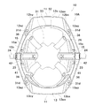
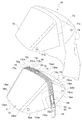
まず、構成を簡単に説明すると、図1乃至図3に示す、この実施の形態1の折畳み式帽子10は子供用の折り畳み式帽子であり、「本体部」としての折畳み式帽子本体部10Aは園児、学童等の子供が頭に被るのに適した大きさに形成されている。但し、折畳み式帽子10は子供用のみに限定されることはなく、折畳み式帽子本体部10Aが平均的な大人が頭に被るのに適した大きさに形成されていてもよい。   First, the configuration will be briefly described. The foldable cap 10 of the first embodiment shown in FIGS. 1 to 3 is a foldable cap for children, and a foldable cap main body 10A as a “main body” is as follows. The size is suitable for children such as kindergarten and schoolchildren to wear on their heads. However, the foldable hat 10 is not limited to children only, and the foldable hat main body 10A may be formed in a size suitable for an average adult to wear on the head.

図1乃至図3に示す折畳み式帽子本体部10Aは、ポリプロピレン等、剛性が高く、かつ折り曲げに対する強度が高い樹脂により一体成形されている。折畳み式帽子本体部10Aは、有色不透明、有色透明、無色透明にすることができる。有色透明、無色透明であれば、避難時に前方及び側方に視野が広がるので、有効である。   The foldable hat main body 10A shown in FIGS. 1 to 3 is integrally formed of a resin having high rigidity and high strength against bending, such as polypropylene. The foldable hat main body 10A can be colored, opaque, colored, transparent, and colorless and transparent. Colored and colorless and transparent are effective because the field of view widens forward and to the side during evacuation.

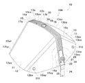
この折畳み式帽子本体部10Aは、前辺に連続して庇部11を有する一枚板状の前頭被覆用の「平板」としての前側平板12と、一枚の板状の後頭被覆用の「平板」としての後側平板13とを有している。前側平板12と後側平板13とは、平板状体で平板状態で形状が安定するように形成されている。   The foldable hat main body 10A includes a front flat plate 12 as a single plate-like frontal covering “flat plate” having a flange 11 continuously on the front side, and a single plate-like rear head covering “ And a rear flat plate 13 as a “flat plate”. The front flat plate 12 and the rear flat plate 13 are formed in a flat plate shape so that the shape is stable in a flat plate state.

前側平板12は、正面視略台形に形成された「平板本体部」としての前側平板本体部12ax、正面視略三角形に形成された「平板本体部」としての左側平板本体部12ay及び右側平板本体部12azを備えている。また、前側平板本体部12axと左側平板本体部12ayとの間には長手方向(図1における上下方向)に沿って帯状の「ヒンジ部」としての第一ヒンジ部12bxが、前側平板本体部12axと右側平板本体部12azとの間には長手方向に沿って略帯状の「ヒンジ部」としての第二ヒンジ部12byをそれぞれ備えている。   The front flat plate 12 includes a front flat plate main body portion 12ax as a “flat plate main body portion” formed in a substantially trapezoidal shape in front view, a left flat plate main body portion 12ay as a “flat plate main body portion” formed in a substantially triangular shape in front view, and a right flat plate main body. A portion 12az is provided. Further, a first hinge portion 12bx as a strip-like “hinge portion” along the longitudinal direction (vertical direction in FIG. 1) is provided between the front flat plate main body portion 12ax and the left flat plate main body portion 12ay. And a right flat plate main body portion 12az are each provided with a second hinge portion 12by as a substantially hinge-like “hinge portion” along the longitudinal direction.

同様に、後側平板13は、正面視略台形に形成された「平板本体部」としての後側平板本体部13ax、正面視略三角形に形成された「平板本体部」としての左側平板本体部13ay及び右側平板本体部13azを備えている。また、後側平板本体部13axと左側平板本体部13ayとの間には長手方向に沿って帯状の「ヒンジ部」としての第三ヒンジ部13bxが、後側平板本体部13axと右側平板本体部13azとの間には長手方向に沿って略帯状の「ヒンジ部」としての第四ヒンジ部13byをそれぞれ備えている。   Similarly, the rear flat plate 13 includes a rear flat plate main body portion 13ax as a “flat plate main body portion” formed in a substantially trapezoidal shape in front view, and a left flat plate main body portion as a “flat plate main body portion” formed in a substantially triangular shape in front view. 13ay and the right side flat plate main-body part 13az are provided. Further, a third hinge portion 13bx as a strip-like “hinge portion” along the longitudinal direction is provided between the rear flat plate main body portion 13ax and the left flat plate main body portion 13ay. A fourth hinge portion 13by as a substantially “belt-shaped” hinge portion along the longitudinal direction is provided between the first hinge portion 13az and the third hinge portion 13az.

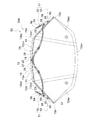
図1及び図3に示す通り、折畳み式帽子本体部10Aを展開した状態で頭部に被れる形状である帽子状態(以下単に「帽子状態」と称する。)としたときに、前側平板12の各平板本体部12ax,12ay,12azのそれぞれは平板の状態で頭部の前頭部略全域と両頭側部略全域とを覆い、また後側平板13の各平板本体部13ax,13ay,13azのそれぞれは平板の状態で頭部の後頭部略全域と両頭側部略全域とを覆い、第一〜第四ヒンジ部12bx,12by,13bx,13byは各平板本体部12ax,12ay,12az,13ax,13ay,13azの境界部分における帽子状態を形成する際に折り曲げなければならない最小限の箇所に配設された状態となっている。これにより、帽子状態の形成を支障なく行いつつ、頭部の略全域を剛性の高い各平板本体部12ax,12ay,12az,13ax,13ay,13azで覆うことで落下物等の衝撃から頭部を確実に保護できる。   As shown in FIGS. 1 and 3, when the foldable hat main body 10 </ b> A is unfolded and is in a hat state (hereinafter simply referred to as “hat state”) that is covered with the head, Each of the flat plate main body portions 12ax, 12ay, and 12az covers the entire frontal region of the head and the entire region of both head side portions in a flat plate state, and each of the flat plate main body portions 13ax, 13ay, and 13az of the rear flat plate 13 is covered. Each of the flat plate covers substantially the entire back of the head and both sides of the head, and the first to fourth hinge portions 12bx, 12by, 13bx, and 13by are the flat plate body portions 12ax, 12ay, 12az, 13ax, and 13ay. , 13az are arranged at the minimum positions that must be bent when forming the hat state at the boundary portion. Accordingly, the head can be protected from the impact of falling objects by covering the substantially entire area of the head with the highly rigid flat plate main body portions 12ax, 12ay, 12az, 13ax, 13ay, 13az while forming the hat state without any trouble. It can be reliably protected.

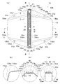
図3の(b)に示す通り、前側平板12の前側平板本体部12ax、左側平板本体部12ay、右側平板本体部12azは板厚が厚く(例えば2.5mm程度)、折り曲げによる弾性変形は生じにくくなるように形成されている。一方、第一ヒンジ部12bx、第二ヒンジ部12byは前記各平板本体部12ax,12ay,12azよりも板厚が薄く(例えば0.8mm程度)、折り曲げにより容易に弾性変形するように形成されている。同様に、後側平板13の後側平板本体部13ax,左側平板本体部13ay、右側平板本体部12azは折り曲げによる弾性変形が生じにくくなるように板厚が厚く形成され、一方、第三ヒンジ部13bx、第四ヒンジ部13byは折り曲げにより容易に弾性変形するように前記各平板本体部13ax,13ay,13azよりも板厚が薄く形成されている。   As shown in FIG. 3B, the front plate body 12ax, the left plate body 12ay, and the right plate body 12az of the front plate 12 are thick (for example, about 2.5 mm), and elastic deformation due to bending occurs. It is formed to be difficult. On the other hand, the first hinge portion 12bx and the second hinge portion 12by are thinner than the flat plate body portions 12ax, 12ay, 12az (for example, about 0.8 mm) and are formed so as to be easily elastically deformed by bending. Yes. Similarly, the rear flat plate main body portion 13ax, the left flat plate main body portion 13ay, and the right flat plate main body portion 12az are formed thick so that elastic deformation due to bending is less likely to occur, while the third hinge portion. 13bx and the fourth hinge portion 13by are formed thinner than the respective plate main body portions 13ax, 13ay, 13az so as to be easily elastically deformed by bending.

図2に示す通り、前記前側平板12の後辺12cは、正面視の状態で水平状の「周縁部」としての中央縁12cxと該中央縁12cxの左右両側に連設された外側端下がりの「周縁部」としての傾斜縁12cy,12czとを有する張り出し形状にされている。又、同様に、図1に示す後側平板13の前辺13cは、正面視(図示せず)の状態で、水平状の「周縁部」としての中央縁13cxと、該中央縁13cxの左右両側に連設された外側端下がりの「周縁部」としての傾斜縁13cy,13czとを有する張り出し形状にされている。そして、前記前側平板12の後辺12cと前記後側平板13の前辺13cとは、後述する連結部15に連結されている。なお、前記中央縁12cx及び中央縁13cxは、水平状にされているが、緩やかなカーブ状にすることができるし、同様に、前側平板12の前記傾斜縁12cy,12cz及び後側平板13の傾斜縁13cy,13czを緩やかなカーブ状にすることができる。要するに、前側平板12の後辺12c及び後側平板13の前辺13cは、その中央部分が張り出し、該中央部分に連続する両端側部分が傾斜した形状を呈するようにされていれば足りる。   
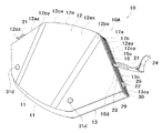
As shown in FIG. 2, the rear side 12c of the front flat plate 12 has a central edge 12cx as a horizontal "peripheral edge" in a front view, and a lower end of the outer edge connected to the left and right sides of the central edge 12cx. It has an overhanging shape having inclined edges 12 cy and 12 cz as “peripheral portions”. Similarly, the front side 13c of the rear flat plate 13 shown in FIG. 1 has a central edge 13cx as a horizontal “periphery” in the front view (not shown), and left and right sides of the central edge 13cx. It has an overhanging shape having inclined edges 13 cy and 13 cz as “peripheral edge portions” that are provided on both sides of the outer end downward. And the rear side 12c of the said front side flat plate 12 and the front side 13c of the said rear side flat plate 13 are connected with the connection part 15 mentioned later. The central edge 12cx and the central edge 13cx are horizontal, but can be gently curved. Similarly, the inclined edges 12cy and 12cz of the front flat plate 12 and the rear flat plate 13 can be formed. The inclined edges 13cy and 13cz can be formed into a gentle curve. In short, it is sufficient that the rear side 12c of the front flat plate 12 and the front side 13c of the rear flat plate 13 have a shape in which the central portion projects and both end side portions continuous to the central portion are inclined.

連結部15は、長手方向の略中央部分において幅方向(図3の(a)に示す左右方向)に連続する平面視略帯状に形成されている。連結部15の両縁側部分にはそれぞれ前側止着片部17a、後側止着片部17bを有する。そして、連結部15の両止着片部17a,17bは、前側平板12の水平状中央縁12cx近傍及び外側端下がりの傾斜縁12cy,12cz近傍と後側平板13の水平状中央縁近傍及び外側端下がりの傾斜縁近傍に連結された状態で止着されている。したがって、連結部15は、前方又は後方から見た場合、前側平板12の張り出し形状後辺12c及び後側平板13の張り出し形状前辺13cに略沿った形状になる。   The connecting portion 15 is formed in a substantially band shape in plan view that is continuous in the width direction (the left-right direction shown in FIG. 3A) at a substantially central portion in the longitudinal direction. The both side portions of the connecting portion 15 respectively have a front side fastening piece portion 17a and a rear side fastening piece portion 17b. Further, both fastening pieces 17a and 17b of the connecting portion 15 are provided in the vicinity of the horizontal central edge 12cx of the front flat plate 12 and in the vicinity of the inclined edges 12cy and 12cz of the outer end downward and in the vicinity of the horizontal central edge of the rear flat plate 13 and the outer side. It is fastened in a state of being connected to the vicinity of the inclined edge at the lower end. Therefore, when viewed from the front or the rear, the connecting portion 15 has a shape substantially along the protruding shape rear side 12 c of the front flat plate 12 and the protruding shape front side 13 c of the rear flat plate 13.

つまり、前記連結部15には、図1及び図3に示すように、折曲げ水平部15aと、該折曲げ水平部15aの両端から連続する「側片部」としての左右の折曲げ傾斜部15b,15cとが形成される。   That is, as shown in FIGS. 1 and 3, the connecting portion 15 includes a bent horizontal portion 15a and left and right bent inclined portions as “side piece portions” continuous from both ends of the bent horizontal portion 15a. 15b and 15c are formed.

なお、図示しないが、連結部15は、折曲げ水平部15aに対する左右の折曲げ傾斜部15b,15cの湾曲形状を容易に形成できるように、前側平板12の各平板本体部12ax,12ay,12azや後側平板13の各平板本体部13ax,13ay,13azよりも板厚が薄く形成されている。   Although not shown in the drawings, the connecting portion 15 has the plate main body portions 12ax, 12ay, 12az of the front plate 12 so that the bent shape of the left and right bent inclined portions 15b, 15c with respect to the bent horizontal portion 15a can be easily formed. And the plate | board thickness is formed thinner than each flat plate main-body part 13ax, 13ay, 13az of the back side flat plate 13. FIG.

また、図4及び図8に示すように、連結部15の表面には、幅方向に沿って連続する複数(この実施の形態1においては4つ)の突起状部30が外方に向けて突出形成されている。この突起状部30は、外部からの衝撃によって変形し衝撃を吸収できる形状に形成されている。   Further, as shown in FIGS. 4 and 8, a plurality of (four in the first embodiment) projecting portions 30 extending in the width direction are directed outward on the surface of the connecting portion 15. Protrusions are formed. The protruding portion 30 is formed in a shape that can be deformed by an external impact and absorb the impact.

一方、図3の(c)及び(d)に示すように、両止着片部17a,17bは、前側平板12の後辺12cよりもやや前側寄り、及び後側平板13の前辺13cよりもやや後側寄りにおいてそれぞれ前側平板12及び後側平板13に連結されている。そして、図3の(c)に示す通り、折畳み式帽子本体部10Aを展開した状態において、止着片部17a(又は17b)から前側平板12の後辺12c(又は後側平板の前辺13c)までの高さT1よりもよりも突起状部30の高さT2の高さの方が高くなるように形成されている。   On the other hand, as shown in FIGS. 3C and 3D, both fastening pieces 17 a and 17 b are slightly closer to the front side than the rear side 12 c of the front plate 12 and from the front side 13 c of the rear plate 13. It is connected to the front side flat plate 12 and the rear side flat plate 13 respectively slightly closer to the rear side. Then, as shown in FIG. 3C, in the state in which the foldable cap body 10A is unfolded, the fastening plate 17a (or 17b) to the rear side 12c of the front flat plate 12 (or the front side 13c of the rear flat plate). ), The height T2 of the protrusion 30 is higher than the height T1.

図3の(a)に示すように、折曲げ水平部15aの略中央部、即ち折畳み式帽子本体部10Aの頂部には、幅方向に長い平面視略矩形の貫通孔部18が貫通形成されている。この貫通孔部18には繋留止部19の固定片20(後述)が挿通されて止着される。   As shown in FIG. 3A, a substantially rectangular through-hole portion 18 that is long in the width direction is formed through the substantially horizontal portion of the folded horizontal portion 15a, that is, the top portion of the folding hat main body portion 10A. ing. A fixing piece 20 (described later) of the anchoring portion 19 is inserted into the through-hole portion 18 and fixed thereto.

また、折曲げ傾斜部15b,15cの外側(正面側)には、それぞれ「展開状態保持手段」としての係止部21と、この係止部21に係脱自在に設けられた「展開状態保持手段」としての被係止部22とを有している。係止されていない状態において、被係止部22は係止部21の略垂直下方に配設されている。この係止部21及び被係止部22は、係止部21を被係止部22に係止させることで、折畳み式帽子本体部の展開状態(後述)を保持する機能を奏するものである。係止部21及び被係止部22は、剛性が高く加工が容易な材料例えばポリプロピレン等の樹脂によって形成されている。   Further, on the outer side (front side) of the bending inclined portions 15b and 15c, a locking portion 21 as a “deployed state holding means” and a “deployed state holding” provided detachably on the locking portion 21 are provided. And a locked portion 22 as means. When not locked, the locked portion 22 is disposed substantially vertically below the locking portion 21. The locking portion 21 and the locked portion 22 have a function of holding the unfolded state (described later) of the foldable hat main body portion by locking the locking portion 21 to the locked portion 22. . The locking portion 21 and the locked portion 22 are made of a material having high rigidity and easy processing, for example, a resin such as polypropylene.

図9に示す通り、係止部21は、略円環状に形成されている。そして、係止部21の一方側には繋留紐23(後述)の一端部が連結されており、他方側には顎紐24(後述)の端部がそれぞれ連結されている。被係止部22は、図5及び図6に示す、折曲げ傾斜部15b,15cに貫通形成された被係止部嵌合孔部29,29に嵌合されて固着され、折曲げ傾斜部15b,15cの正面側に突設されている。被係止部22は、略突起状であって先端部に拡径部25が形成されている。これにより、係止部21の内部に挿入されて係止可能となるように形成されている。   As shown in FIG. 9, the locking portion 21 is formed in a substantially annular shape. One end of a tether 23 (described later) is connected to one side of the locking portion 21, and the end of a chin strap 24 (described later) is connected to the other side. The locked portion 22 is fitted and fixed to the locked portion fitting holes 29 and 29 formed through the bending inclined portions 15b and 15c shown in FIGS. 5 and 6, and the bent inclined portion. It protrudes on the front side of 15b and 15c. The locked portion 22 has a substantially protruding shape, and a diameter-enlarged portion 25 is formed at the tip. Thereby, it forms in the inside of the latching | locking part 21, and it is formed so that latching is possible.

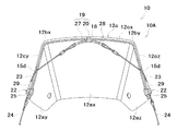
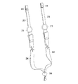
一方、図7に示す通り、折畳み式帽子本体部10Aの内側(即ち、被った際に頭部に対向する側)には、繋留止部19と、「繋留体」としての一対の繋留紐23,23と、ハンモック26とが配設されている。   On the other hand, as shown in FIG. 7, on the inner side of the foldable hat main body portion 10 </ b> A (that is, the side facing the head when worn), the anchoring portion 19 and a pair of tethers 23 as “tethers” , 23 and a hammock 26 are disposed.

繋留止部19は剛性が高く加工が容易な材料、例えばポリプロピレンのような樹脂にて形成されている。図5及び図6に示す通り、繋留止部19は繋留本体部27と固定片20とを有している。   The anchoring portion 19 is formed of a material having high rigidity and easy processing, for example, a resin such as polypropylene. As shown in FIGS. 5 and 6, the anchoring portion 19 includes an anchoring main body portion 27 and a fixing piece 20.

繋留本体部27は一方向に長い板状に形成されると共に、長手方向両端部に紐通し孔部28,28が開口形成されている。固定片20は繋留本体部27の長手方向中央部において上側に突出形成された軸部の上側に、繋留本体部27の幅方向に長い略矩形に形成されている。この固定片20の形状は、折曲げ水平部15aの貫通孔部18の形状と略等しい。即ち、図1に示す通り、繋留止部19は、固定片20を貫通孔部18に貫通させたのちに約90°回転させることで折曲げ水平部15aに固着させる。   The anchoring main body 27 is formed in a plate shape that is long in one direction, and string-through holes 28 are formed at both ends in the longitudinal direction. The fixed piece 20 is formed in a substantially rectangular shape that is long in the width direction of the anchoring main body portion 27 on the upper side of the shaft portion that protrudes upward in the central portion in the longitudinal direction of the anchoring main body portion 27. The shape of the fixed piece 20 is substantially equal to the shape of the through hole portion 18 of the bent horizontal portion 15a. That is, as shown in FIG. 1, the anchoring portion 19 is fixed to the bent horizontal portion 15 a by rotating the fixing piece 20 through the through-hole portion 18 and then rotating about 90 °.

繋留紐23は、剛性が高く柔軟な樹脂繊維によって帯状に形成されている。繋留紐23の一端部側は左右の折曲げ傾斜部15b,15cの外側に配設されて、繋留紐23の一端部は係止部21に連結されている。一方、図4及び図8に示す通り、繋留紐23は左右の折曲げ傾斜部15b,15cにそれぞれ貫通形成された繋留紐挿通孔部15dを貫通して、図6に示す通り、繋留紐23の他端部側は折畳み式帽子本体部10Aの内側まで延長され、繋留紐23の他端部は、繋留本体部27の紐通し孔部28に挿通されて繋留部27に繋留されている。   The tether 23 is formed in a strip shape with a highly rigid and flexible resin fiber. One end portion side of the tether 23 is disposed outside the left and right bent inclined portions 15 b and 15 c, and one end portion of the tether 23 is connected to the locking portion 21. On the other hand, as shown in FIGS. 4 and 8, the tether 23 penetrates the tether string insertion hole 15d formed through the left and right bent inclined portions 15b and 15c, respectively, and as shown in FIG. The other end of the tie is extended to the inside of the folding hat main body 10 </ b> A, and the other end of the tether 23 is inserted into the tether hole 28 of the tether main body 27 and is tethered to the tether 27.

これにより、それぞれ繋留紐23,23の他端部が、折畳み式帽子本体部10Aの内部で繋留止部19によって互いに連結された状態となり、また、それぞれの繋留紐23,23は折畳み式帽子本体部10Aの頂部に固定される。また、図6に示す通り、係止部21を被係止部22に係止させたとき、それぞれの繋留紐23,23は折畳み式帽子本体部10Aの内部で緊張した状態となり、図5に示す通り、係止部21が被係止部22に係止されていないときにはそれぞれの繋留紐23,23は折畳み式帽子本体部10aの内部で弛んだ状態になるように形成されている。   As a result, the other end portions of the tethers 23 and 23 are connected to each other by the tethers 19 inside the foldable hat main body 10A, and the tethers 23 and 23 are connected to the foldable hat main body. It is fixed to the top of the part 10A. Further, as shown in FIG. 6, when the locking portion 21 is locked to the locked portion 22, the tethers 23 and 23 are in tension in the foldable hat main body portion 10A. As shown, when the locking portion 21 is not locked to the locked portion 22, the tethers 23, 23 are formed so as to be loosened inside the foldable hat main body portion 10a.

また、図9に示す通り、繋留紐23,23の他端部側にはそれぞれ留め具41,41が設けられている。この留め具41はホック、スナップボタン等、係脱可能な一対の部材により形成され、図5及び図6に示すように、この一対の部材同士が係合して繋留紐23の他端部側が繋留部27に繋留された状態を保持できるようになっている。また、留め具41は繋留紐23に極めて強い衝撃や極めて引っ張り力が加わったときに上記一対の部材同士の係合が解除されて、この衝撃や引っ張り力によって繋留紐23や折畳み式帽子本体部10Aの破損を防止できるように構成されている。   Moreover, as shown in FIG. 9, the fasteners 41 and 41 are provided in the other end part side of the tether 23 and 23, respectively. The fastener 41 is formed by a pair of members that can be engaged and disengaged, such as a hook and a snap button. As shown in FIGS. 5 and 6, the pair of members are engaged with each other so that the other end side of the tether 23 is The state tethered to the tether part 27 can be maintained. The fastener 41 is disengaged between the pair of members when a very strong impact or a tensile force is applied to the tether 23, and the tether 23 or the folding hat main body portion is released by the impact or the tensile force. It is comprised so that breakage of 10A can be prevented.

図7に示す通り、ハンモック26は、頭頂部を抑える頭頂抑え部31aと、この頭頂抑え部31aから複数延長された計4本の略帯状の延長片部31bとを有し、この各延長片部31bの先端部に設けられた取付部31cが前側平板12及び後側平板13に取付リベット31dにより回動自在に取り付けられている。   As shown in FIG. 7, the hammock 26 has a parietal restraint portion 31a for restraining the parietal portion, and a total of four substantially strip-like extension pieces 31b extended from the parietal restraint portion 31a. A mounting portion 31c provided at the tip of the portion 31b is rotatably mounted on the front flat plate 12 and the rear flat plate 13 by mounting rivets 31d.

それら取付部31cは、合成樹脂で形成されて所定の剛性を有し、他の部分が繊維により帯状に成形されて柔軟性を有している。   The attachment portions 31c are made of synthetic resin and have a predetermined rigidity, and other portions are formed into a belt shape with fibers and have flexibility.

また、頭頂抑え部31aは、柔軟性を有する合成樹脂(ビニールレザー)から形成されている。   Moreover, the top restraint part 31a is formed from the synthetic resin (vinyl leather) which has a softness | flexibility.

一方、ヘッドバンド32は、頭部前側を押さえる合成樹脂製の所定の剛性を有する前側バンド部33と、頭部後側を押さえる合成樹脂製の所定の剛性を有する後側バンド部34とが、連結部15に対応した位置に設けられた柔軟性を有する連結部35を介して折り畳み可能に設けられている。   On the other hand, the headband 32 includes a front band portion 33 having a predetermined rigidity made of synthetic resin that holds the front side of the head and a rear band portion 34 having a predetermined rigidity made of synthetic resin that holds the rear side of the head. It is provided so as to be foldable via a flexible connecting portion 35 provided at a position corresponding to the connecting portion 15.

また、その前側バンド部33及び後側バンド部34がそれぞれ延長片部31bの取付部31cに連結リベット36を介して回動自在に設けられている。   Further, the front band part 33 and the rear band part 34 are provided rotatably on the attachment part 31c of the extension piece part 31b via a connecting rivet 36, respectively.

図7に示す通り、前側バンド部33と後側バンド部34とは、頭部の両側部を押さえる位置にそれぞれ配設されたアジャスタ42,42によって連結されている。このアジャスタ42は柔軟性のある帯状の部材によって形成され、両端部には例えば面ファスナのような係止部材(図示せず)が設けられている。図7に示す通り、アジャスタ42を前側バンド部33と後側バンド部34とにそれぞれ設けられた挿通孔部に挿通されると共に、アジャスタ42の係止部材同士を係止させることで前側バンド部33と後側バンド部34とを連結される。更に、アジャスタ42の係止部材同士の係止位置をアジャスタ42の長手方向に調節することで、前側バンド部33と後側バンド部34とを使用者の頭部の大きさにフィットするように調節することができる。アジャスタ42を頭部の両側部を押さえる位置にそれぞれ配設したことにより、折畳み式帽子本体部10Aを頭部に被った後も使用者自身が簡単にアジャスタ42を調節してハンモック26を頭部にフィットさせることができる。   As shown in FIG. 7, the front band portion 33 and the rear band portion 34 are connected to each other by adjusters 42 and 42 that are disposed at positions where both side portions of the head are pressed. The adjuster 42 is formed of a flexible belt-like member, and a locking member (not shown) such as a hook-and-loop fastener is provided at both ends. As shown in FIG. 7, the adjuster 42 is inserted into the insertion hole portions provided in the front band portion 33 and the rear band portion 34, respectively, and the locking members of the adjuster 42 are locked to each other to lock the front band portion. 33 and the rear band part 34 are connected. Further, by adjusting the locking position of the locking members of the adjuster 42 in the longitudinal direction of the adjuster 42, the front band part 33 and the rear band part 34 are fitted to the size of the user's head. Can be adjusted. By arranging the adjusters 42 at positions where both sides of the head are pressed, the user can easily adjust the adjuster 42 and put the hammock 26 on the head even after the foldable hat main body 10A is put on the head. Can be fitted.

更に、図9に示す通り、顎紐24は両端部がそれぞれ係止部21,21に連結されている。また、顎紐24の長手方向略中央部には、顎紐24の締結部分の長さを調節して折畳み式帽子本体部10Aを頭部に固定させるためのするコードストッパ38が設けられている。   Further, as shown in FIG. 9, both ends of the chin strap 24 are connected to the locking portions 21 and 21, respectively. Further, a cord stopper 38 for adjusting the length of the fastening portion of the chin strap 24 to fix the foldable hat main body portion 10A to the head is provided at a substantially central portion in the longitudinal direction of the chin strap 24. .

なお、この実施の形態1の係止部21、被係止部22、繋留止部19、ハンモック26、顎紐24は、折畳み式帽子本体部10Aに対して着脱自在に形成されている。これにより、折畳み式帽子本体部10A、係止部21、被係止部22、繋留止部19、ハンモック26、顎紐24をそれぞれ別工程で製造することができて、製造の容易化と製造コストの低減化とを図ることができる。   In addition, the latching | locking part 21, the latched | locked part 22, the anchoring part 19, the hammock 26, and the chin strap 24 of this Embodiment 1 are formed so that attachment or detachment is possible with respect to 10 A of foldable hat main bodies. Thereby, the foldable hat main body 10A, the locking part 21, the locked part 22, the anchoring part 19, the hammock 26, and the chin strap 24 can be manufactured in separate processes, respectively, and manufacturing is facilitated and manufactured. Cost can be reduced.

次に、この実施の形態1の折畳み式帽子10の作用について説明する。   Next, the operation of the foldable cap 10 of the first embodiment will be described.

この実施の形態1の折畳み式帽子10は、図2及び図5に示すように前側平板12と後側平板13とがそれぞれ平板状態となった状態において、左の折曲げ傾斜部15bの下端部と右の折曲げ傾斜部15cの下端部とを互いに近づく方向に同時に押す。すると、前側平板12の第一ヒンジ部12bx及び第二ヒンジ部12by、後側平板13の第三ヒンジ部13bx及び第四ヒンジ部13byがそれぞれ弾性変形する。これにより前側平板12及び後側平板13を弾性力に抗して変形させることで展開状態とする。このとき、折畳み式帽子本体部10Aは帽子状態となっている。   As shown in FIGS. 2 and 5, the foldable cap 10 according to the first embodiment has a lower end portion of a left bent inclined portion 15b in a state where the front flat plate 12 and the rear flat plate 13 are in a flat plate state, respectively. And the lower end of the right bent inclined portion 15c are simultaneously pushed in a direction approaching each other. Then, the first hinge portion 12bx and the second hinge portion 12by of the front flat plate 12 and the third hinge portion 13bx and the fourth hinge portion 13by of the rear flat plate 13 are elastically deformed, respectively. Thereby, the front side flat plate 12 and the rear side flat plate 13 are brought into a developed state by being deformed against the elastic force. At this time, the foldable hat body 10A is in a hat state.

この状態で折畳み式帽子本体部10Aを頭部に被らせて、折畳み式帽子10の使用者は自ら顎紐24を把持して、この顎紐24を下方に引き下ろす。すると、前側平板12の第一ヒンジ部12bx及び第二ヒンジ部12by、後側平板13の第三ヒンジ部13bx及び第四ヒンジ部13byは更に弾性変形し、その結果一対の繋留紐23,23の一端部側が折畳み式帽子本体部10Aの内部から外側に引き出される。そして、顎紐24の両端部に連結された係止部21,21の内部にそれぞれ被係止部22,22が挿通された状態となる。この状態で、折畳み式帽子10の使用者が顎紐24を離すと、第一ヒンジ部12bx、第二ヒンジ部12by、第三ヒンジ部13bx、第四ヒンジ部13byの弾性力によって繋留紐23,23が繋留止部19側に引っ張られ、繋留紐23,23の緊張により係止部21が被係止部22に係止された状態となり、折畳み式帽子本体部10Aの展開状態が保持される。   In this state, the foldable hat main body 10A is put on the head, and the user of the foldable hat 10 grips the chin strap 24 and pulls the chin strap 24 downward. Then, the first hinge part 12bx and the second hinge part 12by of the front side flat plate 12, and the third hinge part 13bx and the fourth hinge part 13by of the rear side flat plate 13 are further elastically deformed. As a result, the pair of tethers 23, 23 One end side is pulled out from the inside of the folding hat main body 10A. And the to-be-latched parts 22 and 22 will be inserted in the inside of the latching | locking parts 21 and 21 connected with the both ends of the chin strap 24, respectively. In this state, when the user of the foldable cap 10 releases the chin strap 24, the tether 23, the second hinge portion 12by, the third hinge portion 13bx, and the fourth hinge portion 13by are elastically coupled by the elastic force of the first hinge portion 12bx, the second hinge portion 12by, the third hinge portion 13by. 23 is pulled to the anchoring portion 19 side, and the locking portion 21 is locked to the locked portion 22 by the tension of the anchoring cords 23, 23, and the unfolded state of the folding hat main body portion 10A is maintained. .

顎紐24を下方に引っ張るときには、折畳み式帽子10の使用者がさほど大きな力を加えていなくても第一ヒンジ部12bx、第二ヒンジ部12by、第三ヒンジ部13bx、第四ヒンジ部13byを容易に弾性変形させることができる。即ち、折畳み式帽子10の使用者は、大きな力を要することなく簡単な操作で係止部21を被係止部22に係止させて展開状態を維持させることができる。   When the chin strap 24 is pulled downward, the first hinge part 12bx, the second hinge part 12by, the third hinge part 13bx, and the fourth hinge part 13by can be moved even if the user of the folding hat 10 does not apply a great force. It can be easily elastically deformed. That is, the user of the foldable cap 10 can maintain the unfolded state by locking the locking portion 21 to the locked portion 22 with a simple operation without requiring a large force.

折畳み式帽子本体部10Aの展開状態が保持された状態となったとき、前側平板本体部12ax、左側平板本体部12ay、右側平板本体部12az、後側平板本体部13ax、左側平板本体部13ay、右側平板本体部13azは頭部の大半の部分を覆っているので、落下物等の衝撃から頭部を確実に守ることができる。   When the unfolded state of the foldable hat main body 10A is maintained, the front flat plate main body 12ax, the left flat plate main body 12ay, the right flat plate main body 12az, the rear flat plate main body 13ax, the left flat plate main body 13ay, Since the right flat plate main body 13az covers most of the head, the head can be reliably protected from impacts such as falling objects.

更に、両止着片部17a,17bは、前側平板12の後辺12cよりもやや前側寄り、及び後側平板13の前辺13cよりもやや後側寄りにおいてそれぞれ前側平板12及び後側平板13に連結されている。そのため、図3の(c)に示す通り、係止部21を被係止部22に係止させたとき、連結部15は前側平板12の後辺12c及び後側平板13の前辺13cよりも内側に引っ込んだ状態となっており、板厚の薄い連結部15に落下物等が直撃し連結部15が破損する事態を防止できる。これにより、頭頂部付近等、連結部15が形成されている箇所に落下物等があったときにおいても、落下物等の衝撃から頭部を確実に保護できる。   Further, the fastening pieces 17a and 17b are respectively located slightly closer to the front side than the rear side 12c of the front side flat plate 12, and slightly closer to the rear side than the front side 13c of the rear side flat plate 13, respectively. It is connected to. Therefore, as shown in FIG. 3C, when the locking portion 21 is locked to the locked portion 22, the connecting portion 15 is from the rear side 12 c of the front flat plate 12 and the front side 13 c of the rear flat plate 13. Is also retracted to the inside, and it is possible to prevent a situation where the fallen object or the like hits the connecting portion 15 with a thin plate thickness and the connecting portion 15 is damaged. Thereby, even when there is a fallen object or the like near the top of the head or the like where the connecting part 15 is formed, the head can be reliably protected from the impact of the fallen object or the like.

更にまた、連結部15には突起状部30が外方に向けて突出形成されており、この突起状部30は外部からの衝撃に対して容易に変形して衝撃を吸収する。これにより、頭頂部付近等、連結部15が形成されている箇所にの落下物等があったときにこの落下物等の衝撃から頭部を確実に保護できる。   Furthermore, a protruding portion 30 is formed on the connecting portion 15 so as to protrude outward. The protruding portion 30 is easily deformed to absorb an impact from the outside. Thereby, when there is a fallen object or the like near the top of the head or the like where the connecting part 15 is formed, the head can be reliably protected from the impact of the fallen object or the like.

なお、折畳み式帽子本体部10Aを帽子状態から扁平状態に変形させたいときは、折畳み式帽子10の使用者は、折畳み式帽子本体部10Aを頭部に被った状態のままで、顎紐24を下方に引っ張る。これにより、係止部21は被係止部22への係止状態を解除させて係止部21と被係止部22とを離脱させる。このときも、折畳み式帽子10の使用者がさほど大きな力を加えていなくても第一ヒンジ部12bx、第二ヒンジ部12by、第三ヒンジ部13bx、第四ヒンジ部13byを容易に弾性変形させることができる。これにより、折畳み式帽子10の使用者は、大きな力を要することなく簡単な操作で係止部21と被係止部22との係止状態を解除させて、容易に折畳み式帽子本体部10Aを扁平状態とすることができる。   When the foldable hat main body 10A is desired to be deformed from the hat state to the flat state, the user of the foldable hat main body 10A keeps the foldable hat main body portion 10A on the head and keeps the chin strap 24 Pull down. Thereby, the locking part 21 releases the locking state to the locked part 22 and separates the locking part 21 and the locked part 22. Also at this time, the first hinge 12bx, the second hinge 12by, the third hinge 13bx, and the fourth hinge 13by are easily elastically deformed even if the user of the folding hat 10 does not apply a great force. be able to. As a result, the user of the foldable cap 10 can easily release the locking state between the locking portion 21 and the locked portion 22 with a simple operation without requiring a large force, and easily foldable cap main body portion 10A. Can be in a flat state.

以上、この実施の形態1においては、平板状態で形状が安定する部材で成形された前頭被覆用の前側平板12と、平板状態で形状が安定する部材で成形された後頭被覆用の後側平板13と、前側平板12の中央縁12cx、傾斜縁12cy,12czのそれぞれ近傍、及び後側平板13中央縁12cx、傾斜縁12cy,12czのそれぞれ近傍を連結させる連結部15とを備え、前側平板12及び後側平板13の周縁部側の一部が連結部15でそれぞれ連結され、折畳んだ状態で前側平板12及び後側平板13が扁平状態となり、展開した状態で頭部に被れる形状である帽子状態となる折畳み式帽子本体部10Aを有する折畳み式帽子10であって、連結部15における、頭部の側頭面に対面する左右の折曲げ傾斜部15b,15cを互いに接近させることにより、前側平板12と後側平板13とを平板状態から第一〜第四ヒンジ部12bx,12by,13bx,13byに抗して変形させることで展開状態とし、展開状態を保持する展開状態保持手段を備えたことにより、展開状態保持手段の保持機能により展開状態に保持され、保持機能が解除されたときには平板状態で形状が安定する部材の特性により自然に二つ折りの扁平な形にされる折畳み式の、危険を避けるのに向いている帽子を容易に提供できる。   As described above, in the first embodiment, the frontal flat plate 12 for frontal covering formed with a member whose shape is stable in a flat plate state, and the rear flat plate for rearal covering formed with a member whose shape is stable in a flat state. 13 and a connecting portion 15 that connects the vicinity of the central edge 12cx and the inclined edges 12cy and 12cz of the front flat plate 12 and the vicinity of the central edge 12cx and the inclined edges 12cy and 12cz of the rear flat plate 13, respectively. In addition, a part of the peripheral side of the rear flat plate 13 is connected by the connecting portion 15, and the front flat plate 12 and the rear flat plate 13 are flattened in a folded state, and are covered with the head in the unfolded state. A foldable hat 10 having a foldable hat main body portion 10A in a certain hat state, wherein left and right bent inclined portions 15b and 15c facing the temporal surface of the head in the connecting portion 15 are connected to each other. By bringing them closer, the front flat plate 12 and the rear flat plate 13 are deformed against the first to fourth hinge portions 12bx, 12by, 13bx, and 13by from the flat plate state to be in a deployed state, and the deployed state is maintained. By providing the state holding means, it is held in the expanded state by the holding function of the extended state holding means, and when the holding function is released, the flat shape is naturally folded into two due to the characteristics of the member whose shape is stable in the flat plate state. You can easily provide a foldable hat that is oriented to avoid danger.

また、この実施の形態1においては、展開状態保持手段は、側辺部の外側に設けられた係止部21と、係止部21に係脱自在に設けられた被係止部22とを有し、一端部が係止部21に連結されると共に、左右の折曲げ傾斜部15b,15cを貫通して内部まで延長された繋留紐23を備え、折畳み式帽子本体部10Aを頭部に固定させる顎紐24の端部が係止部21に連結されて、顎紐24を引くことで係止部21が被係止部22に係止されて、展開状態が保持されるように構成されたことにより、使用者が頭部に折畳み式帽子本体部10Aを被った状態で顎紐24の長さを調節するための操作と同様の操作を自ら行うことで簡単に係止部21を被係止部22に係止させることが可能になる。また、折畳み式帽子本体部10Aを被った状態で使用者が自ら顎紐24を引き下ろせば、小さな力で前側平板12及び後側平板13を弾性変形させることができ、よって顎紐24に連結された係止部21を小さな力で被係止部22に係止されることができる。これにより、簡易な操作と小さい力とで確実に展開状態保持手段を機能させることができる。   In the first embodiment, the unfolded state holding means includes a locking portion 21 provided outside the side portion and a locked portion 22 provided detachably on the locking portion 21. And has one end portion connected to the locking portion 21 and a tether 23 extending through the left and right bent inclined portions 15b and 15c to the inside, and the folding hat main body portion 10A on the head. The end portion of the chin strap 24 to be fixed is connected to the locking portion 21, and the locking portion 21 is locked to the locked portion 22 by pulling the chin strap 24 so that the unfolded state is maintained. As a result, the user can easily hold the locking portion 21 by performing the same operation as the operation for adjusting the length of the chin strap 24 while the user wears the foldable hat main body 10A on the head. It is possible to lock the locked portion 22. Further, if the user pulls down the chin strap 24 while wearing the foldable hat main body 10A, the front flat plate 12 and the rear flat plate 13 can be elastically deformed with a small force. The locked portion 21 can be locked to the locked portion 22 with a small force. As a result, the unfolded state holding means can function reliably with a simple operation and a small force.

更に、この実施の形態1においては、折畳み式帽子本体部10Aを頭部に被った後に係止部21と被係止部22とを連結させるため、使用者はまず折畳み式帽子本体部10Aを自らの頭部にかぶり、次いで係止部21を被係止部22に係止させることになる。そのため、地震等の緊急災害時には、使用者は展開状態の保持を完成させる前に取り急ぎ折畳み式帽子本体部10Aを頭部にかぶり、落下物等から頭部を保護することができる。これにより、緊急災害時においても迅速に頭部を保護することができる。   Furthermore, in this Embodiment 1, in order to connect the latching | locking part 21 and the to-be-latched part 22 after covering the foldable hat main-body part 10A on a head, a user first folds-down hat main-body part 10A. It is covered with its own head, and then the locking portion 21 is locked to the locked portion 22. Therefore, in the event of an emergency disaster such as an earthquake, the user can quickly cover the head with the foldable hat main body 10A before completing the maintenance of the unfolded state to protect the head from falling objects. Thereby, the head can be quickly protected even in an emergency disaster.

この実施の形態1においては、繋留紐23の他端部が、繋留止部19によって折畳み式帽子本体部10Aの内部の頂部に固定されていることにより、折畳み式帽子本体部10Aを被ったときに繋留紐23が頭部に接触することのない位置に繋留紐23を配設することができる。これにより、折畳み式帽子本体部10Aを被ったときの装着感を良好にすると共に、落下物の接触等による衝撃で繋留紐23が頭部にぶつかって使用者が負傷するような事態を防止できる。   In this Embodiment 1, when the other end part of the tether 23 is fixed to the top part inside the foldable hat main body part 10A by the anchoring part 19, the foldable hat main body part 10A is covered. The tether 23 can be disposed at a position where the tether 23 does not contact the head. As a result, it is possible to improve the feeling of wearing when the foldable hat main body 10A is worn, and to prevent the user from being injured by the tether 23 hitting the head due to an impact caused by the contact of a falling object or the like. .

この実施の形態1においては、繋留紐23,23の他端部は折畳み式帽子本体部10Aの内部で互いに連結されていることにより、顎紐24を引きおろしたときの前側平板12及び後側平板13の弾性変形の度合いを左右均等にすることができる。これにより、左右の係止部21,21を同じタイミングで被係止部22,22に係止させることができて、左右の係止部21,21と被係止部22,22との係止タイミングのずれによる係止の不具合を防止することができる。   In the first embodiment, the other ends of the tethers 23, 23 are connected to each other inside the folding hat main body 10A, so that the front flat plate 12 and the rear side when the chin strap 24 is pulled down. The degree of elastic deformation of the flat plate 13 can be made equal to the left and right. As a result, the left and right locking portions 21 and 21 can be locked to the locked portions 22 and 22 at the same timing, and the engagement between the left and right locking portions 21 and 21 and the locked portions 22 and 22 can be achieved. It is possible to prevent a locking failure due to a stop timing shift.

この実施の形態1においては、前側平板12と後側平板13とは、前側平板本体部12ax、左側平板本体部12ay、右側平板本体部12az、後側平板本体部13ax、左側平板本体部13ay、右側平板本体部13azと、これら平板本体部12ax,12ay,12az,13ax,13ay,13azよりも板厚の薄い第一〜第四ヒンジ部12bx,12by,13bx,13byとを備え、折畳み式帽子本体部10Aは、前側平板12の第一、第二ヒンジ部12bx,12byと後側平板13の第三、第四ヒンジ部13bx,13byとがそれぞれ折り曲げられることで変形させられて前記展開状態に形成されることにより、頭部の大部分を板厚が厚くて剛性の高い平板本体部12ax,12ay,12az,13ax,13ay,13azにて形成しつつ、弾性変形の容易な第一〜第四ヒンジ部12bx,12by,13bx,13byを折り曲げることで帽子形状を容易に形成できる。これにより、帽子形状の形成が容易でしかも落下物等の衝撃から頭部を確実に保護できる折畳み式帽子10を提供することができる。   In the first embodiment, the front flat plate 12 and the rear flat plate 13 include a front flat plate main body portion 12ax, a left flat plate main body portion 12ay, a right flat plate main body portion 12az, a rear flat plate main body portion 13ax, a left flat plate main body portion 13ay, A foldable hat body comprising a right flat plate body portion 13az and first to fourth hinge portions 12bx, 12by, 13bx, 13by that are thinner than the flat plate body portions 12ax, 12ay, 12az, 13ax, 13ay, 13az. The portion 10A is deformed by bending the first and second hinge portions 12bx and 12by of the front flat plate 12 and the third and fourth hinge portions 13bx and 13by of the rear flat plate 13 and formed in the unfolded state. As a result, the plate body portions 12ax, 12ay, 12az, 13ax, 13a having a large plate thickness and a high rigidity are formed on most of the head. , While forming at 13AZ, easy first-fourth hinge portion 12bx of elastic deformation, 12by, 13 bx, can easily form a hat shape by bending the 13By. As a result, it is possible to provide a foldable hat 10 that is easy to form a hat shape and can reliably protect the head from an impact such as a falling object.

この実施の形態1においては、折畳み式帽子本体部10Aは樹脂により一体形成されたことにより、ラインによる大量生産に適した折畳み式帽子本体部10Aを提供し、折畳み式帽子10の製造時における歩留まりの向上とコストダウンを図ることができる。   In the first embodiment, the foldable hat main body 10A is integrally formed of resin, so that a foldable hat main body 10A suitable for mass production by a line is provided, and the yield at the time of manufacturing the foldable hat 10 is provided. Improvement and cost reduction.

この実施の形態1においては、係止部21は略円環状に形成されると共に、被係止部22は係止部21の内部に挿入されて係止可能な略突起状に形成されていることにより、係止部21を被係止部22と略同一面上に配設し、係止部21を当該面方向に沿って被係止部22側に移動させることで、係止部21と被係止部22とを簡易且つ確実に係止させることができ、また、係止部21を被係止部22の突出方向に沿って移動させることで簡易且つ確実に係止状態を解除できる。これにより、係止部21と被係止部22との係脱を簡易且つ確実にし、折畳み式帽子10の扁平状態と展開状態とを自在に変化させることが可能になる。   In the first embodiment, the locking portion 21 is formed in a substantially annular shape, and the locked portion 22 is formed in a substantially protruding shape that can be inserted into the locking portion 21 and locked. Accordingly, the locking portion 21 is disposed on substantially the same plane as the locked portion 22, and the locking portion 21 is moved to the locked portion 22 side along the surface direction, whereby the locking portion 21. And the locked portion 22 can be easily and reliably locked, and the locked state can be easily and reliably released by moving the locking portion 21 along the protruding direction of the locked portion 22. it can. Thereby, engagement / disengagement of the latching | locking part 21 and the to-be-latched part 22 is made easy and reliable, and it becomes possible to change freely the flat state and unfolding state of the folding-type cap 10. FIG.

なお、この実施の形態1においては、繋留体を帯状の繋留紐23としたが、これに限定されず、係止部21を折畳み式帽子本体部10Aの一部に繋留して前側平板12と後側平板13との変形状態により係止部21と被係止部22との係脱状態を変えられるものであればどのようなものでもよい。例えば、繋留紐23を金属製ワイヤーのようなもので形成してもよいし、更に、紐状の細長い形状でなくてもよい。   In the first embodiment, the tether is a band-like tether 23. However, the tether is not limited to this, and the locking portion 21 is tethered to a part of the folding hat main body 10A to Any device can be used as long as the engagement / disengagement state between the locking portion 21 and the locked portion 22 can be changed depending on the deformation state of the rear flat plate 13. For example, the tether 23 may be formed of a metal wire or may not be a string-like elongated shape.

この実施の形態1においては、折畳み式帽子本体部10Aは樹脂により一体成形されるものとしたが、これに限定されず、例えば前側平板12、後側平板13、連結部15をそれぞれ別体として製造し、それらを接合して折畳み式帽子本体部10Aを形成してもよい。   In the first embodiment, the foldable hat main body 10A is integrally formed of resin. However, the present invention is not limited to this. For example, the front flat plate 12, the rear flat plate 13, and the connecting portion 15 are separately provided. They may be manufactured and joined to form the foldable hat main body 10A.

この実施の形態1においては、係止部21を顎紐24に連結させたが、これに限定されず、例えば顎紐24と別に設けられた係止用紐を係止部に連結し、この係止用紐を引き下ろすことで係止部21を被係止部22に連結されるものとしてもよい。また、紐以外の手段、例えばホックやレバー等をにより係止部21を被係止部22に係止させる構成としてもよい。   In the first embodiment, the locking portion 21 is connected to the chin strap 24. However, the present invention is not limited to this. For example, a locking cord provided separately from the chin strap 24 is connected to the locking portion. The locking portion 21 may be connected to the locked portion 22 by pulling down the locking string. Moreover, it is good also as a structure which latches the latching | locking part 21 to the to-be-latched part 22 by means other than a string, for example, a hook, a lever, etc.

この実施の形態1においては、繋留紐23を折畳み式帽子本体部10Aの内部にて繋留止部19に固定されているものとしたが、これに限定されず、繋留紐23が折畳み式帽子本体部10Aの外部において繋留止部19に固定されていてもよい。また、一対の繋留紐23,23の他端部同士は、繋留止部19を介さずに、直接連結されていてもよい。   In the first embodiment, the tether 23 is fixed to the tether 19 within the foldable hat main body 10A. However, the tether 23 is not limited to this, and the tether 23 is foldable. It may be fixed to the anchoring part 19 outside the part 10A. Further, the other ends of the pair of tethers 23, 23 may be directly connected without the tether 19.

この実施の形態1においては、前側平板12と後側平板13とは、前側平板本体部12ax、左側平板本体部12ay、右側平板本体部12az、後側平板本体部13ax、左側平板本体部13ay、右側平板本体部13azと、これら平板本体部12ax,12ay,12az,13ax,13ay,13azよりも板厚の薄い第一〜第四ヒンジ部12bx,12by,13bx,13byとを備え、折畳み式帽子本体部10Aは、前側平板12の第一、第二ヒンジ部12bx,12byと後側平板13の第三、第四ヒンジ部13bx,13byとがそれぞれ折り曲げられることで変形させられて展開状態に形成されるものとしたが、これに限定されず、前側平板12と後側平板13の全体が折り曲げることで変形させられて展開状態が形成される構成としてもよい。このように構成することで、折畳み式帽子本体部10Aを全て同じ厚さで製造すればよくなって、製造をより簡易化させることができる。
〔発明の実施の形態2〕
In the first embodiment, the front flat plate 12 and the rear flat plate 13 include a front flat plate main body portion 12ax, a left flat plate main body portion 12ay, a right flat plate main body portion 12az, a rear flat plate main body portion 13ax, a left flat plate main body portion 13ay, A foldable hat main body comprising a right flat plate main body portion 13az and first to fourth hinge portions 12bx, 12by, 13bx, 13by that are thinner than the flat plate main body portions 12ax, 12ay, 12az, 13ax, 13ay, 13az. The portion 10A is deformed by bending the first and second hinge portions 12bx and 12by of the front flat plate 12 and the third and fourth hinge portions 13bx and 13by of the rear flat plate 13 and is formed in an unfolded state. However, the present invention is not limited to this, and the front side flat plate 12 and the rear side flat plate 13 are deformed by being bent so that a developed state is formed. It may be configured to be. By comprising in this way, it will suffice if all foldable hat main-body parts 10A are manufactured with the same thickness, and the manufacturing can be further simplified.
[Embodiment 2 of the Invention]

図10乃至図20はこの発明の実施の形態2を示す。   10 to 20 show a second embodiment of the present invention.

この実施の形態2の折畳み式帽子50の折畳み式帽子本体部50Aにおいては、実施の形態1の折畳み式帽子10の折畳み式帽子本体部10Aにおける係止部21及び被係止部22に代えて、「展開状態保持手段」としての展開状態保持機構51が設けられている点が実施の形態1と相違する。   In the foldable cap body 50A of the foldable cap 50 of the second embodiment, instead of the locking portion 21 and the locked portion 22 in the foldable cap main body 10A of the foldable cap 10 of the first embodiment. The difference from the first embodiment is that a deployment state holding mechanism 51 as a “deployment state holding unit” is provided.

図10乃至図14に示す通り、この展開状態保持機構51は、レバー部材52と、折曲げ傾斜部15b,15cの一部に設けられた保持部材53とを備えている。   As shown in FIGS. 10 to 14, the unfolded state holding mechanism 51 includes a lever member 52 and a holding member 53 provided in a part of the bending inclined portions 15 b and 15 c.

レバー部材52は、剛性が高く、かつ折り曲げに対する強度が高い材料、例えば折畳み式帽子本体部50Aと同じポリプロピレン等により形成されている。レバー部材52は、長手方向先端部側から長手方向略中央部側を形成する略板状のレバー部材本体部54と、レバー部材本体部54よりも長手方向基端部側に突設された一対の脚部55,55とを有する。   The lever member 52 is formed of a material having high rigidity and high strength against bending, for example, the same polypropylene as that of the folding hat main body 50A. The lever member 52 includes a substantially plate-like lever member main body portion 54 that forms the substantially central portion side in the longitudinal direction from the distal end portion in the longitudinal direction, and a pair that protrudes from the lever member main body portion 54 toward the proximal end portion in the longitudinal direction. Leg portions 55, 55.

レバー部材本体部54の長手方向先端部側には、幅方向に細長い顎紐挿通孔56が貫通形成されている。図15に示す通り、この顎紐挿通孔56には顎紐24が挿通され、これにより、顎紐24の端部がレバー部材52の長手方向先端部に連結されている。   A chin string insertion hole 56 that is elongated in the width direction is formed through the lever member main body portion 54 at the distal end side in the longitudinal direction. As shown in FIG. 15, the chin strap 24 is inserted into the chin strap insertion hole 56, whereby the end portion of the chin strap 24 is connected to the longitudinal end portion of the lever member 52.

図15に示す通り、それぞれの脚部55,55の先端部(即ちレバー部材51の長手方向基端部)には、それぞれ略円筒形のピン57が側方に向けて突設されている。これら一対のピン57,57は一対のピン挿通孔61,61(後述)にそれぞれ挿通されて、レバー部材52はこれら一対のピン57,57を中心に上下方向に回動する。   As shown in FIG. 15, substantially cylindrical pins 57 project from the distal ends of the legs 55, 55 (that is, the base end in the longitudinal direction of the lever member 51), respectively. The pair of pins 57 and 57 are inserted into a pair of pin insertion holes 61 and 61 (described later), respectively, and the lever member 52 rotates in the vertical direction around the pair of pins 57 and 57.

また、それぞれの脚部55,55の基端部側(即ちレバー部材52の長手方向略中央部側)には、繋留紐23に繋留される連結棒58が、それぞれの脚部55,55に掛け渡されて配設されている。連結棒58とレバー部材本体部54との間には幅方向に細長い繋留紐挿通孔59が貫通形成されている。図15に示す通り、連結棒58には繋留紐挿通孔59に挿通された繋留紐23の一端部が連結されている。   In addition, on the base end side of each leg portion 55, 55 (that is, the substantially central portion side in the longitudinal direction of the lever member 52), a connecting rod 58 anchored to the tether 23 is attached to each leg portion 55, 55. It is stretched and arranged. A tether string insertion hole 59 elongated in the width direction is formed between the connecting rod 58 and the lever member main body 54. As shown in FIG. 15, one end of the tether 23 inserted through the tether insertion hole 59 is connected to the connecting rod 58.

保持部材53は、板状の保持部材本体部60,60を一対有する。図11に示す通り、それぞれの保持部材本体部60,60は、折曲げ傾斜部15b,15cの長手方向両側部に沿ってそれぞれ離間対向した状態で折曲げ傾斜部15b,15cの外方に向けて突設されている。それぞれの保持部材本体部60にはレバー部材52のピン57を挿通するためのピン挿通孔61が貫通形成されている。それ以外の構成は実施の形態1と同じである。   The holding member 53 has a pair of plate-like holding member main body portions 60 and 60. As shown in FIG. 11, the holding member main body portions 60, 60 are directed outward of the bending inclined portions 15b, 15c in a state of being opposed to each other along both longitudinal sides of the bending inclined portions 15b, 15c. Projecting. Each holding member main body 60 is formed with a pin insertion hole 61 through which the pin 57 of the lever member 52 is inserted. Other configurations are the same as those in the first embodiment.

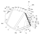
一方、図10、図11に示す通り、折畳み式帽子本体部50Aの左側平板本体部12ay、右側平板本体部12az、左側平板本体部13ay、右側平板本体部13azにはそれぞれ実施の形態1の取付リベット31d,31d,31d,31dに代えて取付リベット62a,62b,62c,62d(但し係止手段62dは図示せず)が設けられている。この取付リベット62a,62b,62c,62dは軸方向両端部が拡径すると共に軸方向略中央部が縮径した形状に形成されている。取付リベット62a,62b,62c,62dの各基端部側は折畳み式帽子本体部50Aの内側に配設されて、実施の形態1の取付リベット31d,31d,31d,31dと同様にハンモック26の取付部31c,31c,31c,31cを取り付けられるようになっており、各先端部側は折畳み式帽子本体部50Aの外側に配設されて、図15乃至図19に示すカバー部材70に開孔形成された係止孔部71a,71b,71c,71d(但し係止孔部71dは図示せず)が係止されるようになっている。   On the other hand, as shown in FIGS. 10 and 11, the left-side flat plate body 12ay, the right-side flat plate main-body portion 12az, the left-side flat plate main-body portion 13ay, and the right-side flat plate main-body portion 13az of the folding hat main body portion 50A are respectively attached to Instead of the rivets 31d, 31d, 31d, 31d, mounting rivets 62a, 62b, 62c, 62d (however, the locking means 62d is not shown) are provided. The mounting rivets 62a, 62b, 62c, and 62d are formed in a shape in which both ends in the axial direction are enlarged and the substantially central portion in the axial direction is reduced in diameter. The base ends of the mounting rivets 62a, 62b, 62c, 62d are arranged inside the folding hat main body 50A, and the hammock 26 of the hammock 26 is the same as the mounting rivets 31d, 31d, 31d, 31d of the first embodiment. The attachment portions 31c, 31c, 31c, and 31c can be attached, and each tip end side is disposed outside the foldable hat main body portion 50A, and has an opening in the cover member 70 shown in FIGS. The formed locking hole portions 71a, 71b, 71c, 71d (however, the locking hole portion 71d is not shown) are locked.

カバー部材70は布地の表面にアルミニウムが蒸着された部材等、折り畳み自在であって難燃性の部材によって形成されている。図16,図17に示す通り、カバー部材70は、前側被覆部材72と、連結部被覆部材73と、後側被覆部材74とが縫製されて、折畳み式帽子本体部50Aの外側を覆うことのできる形状に形成されている。前側被覆部材72は折畳み式帽子本体部50Aの前側平板12に略等しい形状に形成され、連結部被覆部材73は折畳み式帽子本体部50Aの連結部15の形状に略等しい形状に形成されている。図17に示す通り、後側被覆部材74は、上側は折畳み式帽子本体部50Aの後側平板13に略等しい形状に形成され、下側は前側被覆部材72よりも両側方向及び下方に伸長された形状に形成されている。   The cover member 70 is formed of a foldable and flame-retardant member such as a member having aluminum deposited on the surface of the fabric. As shown in FIGS. 16 and 17, the cover member 70 includes a front covering member 72, a connecting portion covering member 73, and a rear covering member 74 that are sewn to cover the outside of the foldable hat main body 50 </ b> A. It is formed in a shape that can be made. The front covering member 72 is formed in a shape substantially equal to the front flat plate 12 of the folding hat main body 50A, and the connecting portion covering member 73 is formed in a shape substantially equal to the shape of the connecting portion 15 of the folding hat main body 50A. . As shown in FIG. 17, the rear covering member 74 has an upper side formed substantially in the same shape as the rear flat plate 13 of the foldable hat main body 50 </ b> A, and a lower side extended in both directions and below the front covering member 72. It is formed in a different shape.

なお、図10乃至図19には図示しないが、折畳み式帽子本体部50Aの表面側において、取付リベット62a及び62b、又は、取付リベット62c及び62dには、バンド75a,75bが係止されている。このバンド75a,75bはいずれも柔軟性のある樹脂にて形成され、両端部には取付リベット62,62,62c,62dのうち何れか一つに係止可能な係止孔部がそれぞれ一つ設けられている。   Although not shown in FIGS. 10 to 19, bands 75a and 75b are locked to the attachment rivets 62a and 62b or the attachment rivets 62c and 62d on the surface side of the folding hat main body 50A. . Each of the bands 75a and 75b is formed of a flexible resin, and each of the ends has one locking hole that can be locked to any one of the mounting rivets 62, 62, 62c, and 62d. Is provided.

上述の構成以外の構成は、実施の形態1と同じである。   Configurations other than those described above are the same as those in the first embodiment.

次に、この実施の形態2の折畳み式帽子50の作用について説明する。   Next, the operation of the foldable cap 50 of the second embodiment will be described.

この実施の形態2の折畳み式帽子50は、図11に示すように前側平板12と後側平板13とがそれぞれ平板状態となった状態において、左右のレバー部材52,52のレバー部材本体部54,54を上方から下方に向けて押し下げる。すると、レバー部材52,52はピン57,57を軸に下方に向けて回動し、レバー部材52,52の動作に伴って繋留紐23,23が折畳み式帽子本体部50Aの外側に向けて引っ張られる。ここで、使用者がレバー部材52,52を押し下げる際には、レバー部材52,52の長手方向基端部側に回動時の支点となるピン57,57が存在し、かつ、長手方向略中央部に作用点となる繋留紐23,23が連結された連結棒58,58が存在し、更に長手方向先端部側に力点となる使用者の把持部分が存在する。そのため、てこの原理により、繋留紐23,23の張力が強くても、使用者は小さい力でレバー部材52,52を回動させ繋留体23,23を引張ることができる。   As shown in FIG. 11, the foldable cap 50 according to the second embodiment has the lever member main body 54 of the left and right lever members 52, 52 in a state where the front flat plate 12 and the rear flat plate 13 are in the flat plate state. , 54 are pushed downward from above. Then, the lever members 52, 52 are rotated downward about the pins 57, 57, and the tethers 23, 23 are directed toward the outside of the folding hat main body 50A in accordance with the operation of the lever members 52, 52. Be pulled. Here, when the user pushes down the lever members 52, 52, the pins 57, 57 serving as fulcrums at the time of rotation exist on the longitudinal base end side of the lever members 52, 52, and the longitudinal direction is substantially the same. There are connecting rods 58, 58 to which the tethers 23, 23 that are the action points are connected at the center, and there is a user's gripping portion that is a force point on the distal end side in the longitudinal direction. Therefore, according to the lever principle, even if the tension of the tethers 23 and 23 is strong, the user can rotate the lever members 52 and 52 and pull the tethers 23 and 23 with a small force.

一方、レバー部材52,52が押し下げられると、繋留紐23,23の張力によってレバー部材52,52が左右の折曲げ傾斜部15b,15cを内側に押圧して、この押圧力により前側平板12の第一ヒンジ部12bx及び第二ヒンジ部12by、後側平板13の第三ヒンジ部13bx及び第四ヒンジ部13byがそれぞれ弾性変形する。これにより前側平板12及び後側平板13を弾性力に抗して変形させることで折畳み式帽子本体部10Aが展開した状態で頭に被れる形状である帽子状態となる。   On the other hand, when the lever members 52 and 52 are pushed down, the lever members 52 and 52 press the left and right bent inclined portions 15b and 15c inward by the tension of the tethers 23 and 23, and the pressing force of the front flat plate 12 is increased. The first hinge portion 12bx and the second hinge portion 12by, and the third hinge portion 13bx and the fourth hinge portion 13by of the rear flat plate 13 are elastically deformed, respectively. As a result, the front flat plate 12 and the rear flat plate 13 are deformed against the elastic force, thereby forming a hat state that is a shape to be put on the head in a state where the folding hat main body portion 10A is unfolded.

そして、レバー部材52を押し下げることで、図13に示す、繋留紐挿通孔部15dの下端部とピン57の外周部外側を結ぶ仮想線L1よりも外側位置P1から同仮想線L1の内側位置P2に、レバー部材の連結棒58の軸心部が移行すると、連結棒58における繋留紐23の張力F1は、傾斜縁12cy(及び傾斜縁12cz)の面に垂直方向の分力F2を発生させる。この分力F2がレバー部材52を一層内側位置P2方向に回転させる力として作用するため、レバー部材52,52は、レバー部材本体部54,54が傾斜縁12cy,12czに接触する状態に押し下げられて固定される。これにより、折畳み式帽子本体部50Aの展開状態が保持される。   Then, by depressing the lever member 52, the inner position P2 of the virtual line L1 from the outer position P1 than the virtual line L1 connecting the lower end of the tether insertion hole 15d and the outer periphery of the pin 57 shown in FIG. In addition, when the axial center portion of the connecting rod 58 of the lever member moves, the tension F1 of the tether 23 on the connecting rod 58 generates a component force F2 in the vertical direction on the surface of the inclined edge 12cy (and the inclined edge 12cz). Since this component force F2 acts as a force for rotating the lever member 52 toward the inner position P2, the lever members 52 and 52 are pushed down so that the lever member main body portions 54 and 54 are in contact with the inclined edges 12cy and 12cz. Fixed. Thereby, the unfolded state of the folding hat main body 50A is maintained.

なお、使用者は、レバー部材本体部54を把持して押し下げる代わりに、顎紐24を把持して下方に引き下ろすことでレバー部材52を下方に向けて回動させ、折畳み式帽子本体部50Aを帽子状態にして展開状態を保持させることもできる。   Instead of grasping and pushing down the lever member main body 54, the user grasps the chin strap 24 and pulls it down to rotate the lever member 52 downward, thereby folding the foldable hat main body 50A. It is also possible to keep the unfolded state in a hat state.

そして、図17及び図18に示すように、折畳み式帽子本体部50Aの表面にカバー部材70を被せ、係止孔部71a,71b,71c,71dを係止部材62a,62b,62c,62dに係止すると、折畳み式帽子本体部50Aの表面にカバー部材70が装着される。この状態で、折畳み式帽子本体部50Aの表面略全域がカバー部材70で覆われた状態となる。この折畳み式帽子本体部50Aを使用者が頭部に被ると、折畳み式帽子本体部50Aによって落下物等の衝撃から頭部を確実に守ることができると共に、カバー部材70によって熱や炎から使用者の頭部を守ることができる。更に、使用者が折畳み式帽子本体部50Aを頭部に被ったとき、カバー部材70の後側被覆部材74は使用者の首周りから肩にかけて覆うことになるため、熱や炎から使用者の首周りから肩にかけて守ることができる。   17 and 18, the cover member 70 is put on the surface of the foldable hat main body 50A, and the locking holes 71a, 71b, 71c, 71d are engaged with the locking members 62a, 62b, 62c, 62d. When locked, the cover member 70 is mounted on the surface of the foldable hat main body 50A. In this state, substantially the entire surface of the foldable hat main body 50 </ b> A is covered with the cover member 70. When the user wears the foldable hat main body 50A on the head, the foldable hat main body 50A can reliably protect the head from the impact of falling objects and the like, and the cover member 70 can be used from heat and flame. Can protect the person's head. Furthermore, when the user wears the foldable hat main body 50A on the head, the rear covering member 74 of the cover member 70 is covered from the user's neck to the shoulder, so that the user's heat and flames can prevent the Can be protected from the neck to the shoulder.

一方、展開状態の折畳み式帽子50の使用が終了し、折畳み式帽子本体部50Aを帽子状態から扁平状態にしたい場合には、使用者は折畳み式帽子本体部50Aを頭部から離脱させ、レバー部材52,52のレバー部材本体部54,54を上方に引きあげる。そして、レバー部材52の連結棒58の軸心部が仮想線Lよりも内側位置P2から外側位置P1に移行して、折畳み式帽子本体部50Aの形状が図13に示す状態から図12に示す状態に移行すると、分力F2によりレバー部材52が押し下げられて固定された状態が解除され、そして繋留紐23,23の緊張が緩み、レバー部材52,52が左右の折曲げ傾斜部15b,15cを内側に押圧する押圧力が弱まる。これにより前側平板12、後側平板13は平板状態になって、折畳み式帽子本体部50Aは扁平状態となる。   On the other hand, when the use of the unfolded folding hat 50 is finished and the folding hat body 50A is desired to be changed from the hat state to the flat state, the user removes the folding hat body 50A from the head and moves the lever. The lever member main body portions 54, 54 of the members 52, 52 are pulled upward. Then, the axial center portion of the connecting rod 58 of the lever member 52 moves from the inner position P2 to the outer position P1 with respect to the imaginary line L, and the shape of the folding hat main body 50A is shown in FIG. 12 from the state shown in FIG. When the state shifts to the state, the lever member 52 is pushed down and fixed by the component force F2, and the tension of the tethers 23 and 23 is loosened, and the lever members 52 and 52 are bent to the left and right bent inclined portions 15b and 15c. The pressing force that presses inward becomes weaker. As a result, the front flat plate 12 and the rear flat plate 13 are in a flat plate state, and the foldable hat main body 50A is in a flat plate state.

そして、扁平状態となった折畳み式帽子本体部50Aにカバー部材70が装着されている場合には、後側被覆部材74を折畳み、図19に示すように、カバー部材70の表面側から取付リベット62a,62b,62c,62dに一対のバンド75a,75bを装着し、後側被覆部材74を折り畳んだ状態でバンド75a,75bで束ねる。これにより、折畳み式帽子本体部50Aにカバー部材70を装着した状態のままで、コンパクトに保管・収容することが可能になる。   When the cover member 70 is attached to the foldable hat main body 50A in the flat state, the rear covering member 74 is folded, and the mounting rivet is attached from the surface side of the cover member 70 as shown in FIG. A pair of bands 75a and 75b are attached to 62a, 62b, 62c, and 62d, and the rear covering member 74 is folded and bundled with the bands 75a and 75b. Thereby, it becomes possible to store and accommodate in a compact manner with the cover member 70 attached to the foldable hat main body 50A.

以上、この実施の形態2によれば、折畳み式帽子本体部50Aの展開状態保持機構51は、側辺部の外側に長手方向基端部側が上下方向に回動自在に設けられたレバー部材52を有し、一端部がレバー部材52の長手方向中間部に連結されると共に、側辺部を貫通して内部まで延長された繋留体23を備え、レバー部材52を下方に向けて回動させることによって繋留体23が引張られて、展開状態が保持されるように構成されたことにより、レバー部材52の先端部側を把持して引き下ろすとレバー部材52は長手方向基端部のピン57を支点に回動し、てこの原理により繋留体23を小さい力で引張ることができると共に折畳み式帽子本体部50Aの展開状態を保持することができる。これにより、簡易な操作と小さい力とで確実に展開状態保持機構51を機能させることができる。   As described above, according to the second embodiment, the unfolded state holding mechanism 51 of the foldable hat main body 50A has the lever member 52 provided on the outer side of the side portion so that the longitudinal base end portion is rotatable in the vertical direction. And has one end portion connected to the middle portion in the longitudinal direction of the lever member 52, and a tether 23 extending through the side portion to the inside, and rotating the lever member 52 downward. As a result, the anchoring body 23 is pulled to be held in the unfolded state, so that when the distal end side of the lever member 52 is gripped and pulled down, the lever member 52 becomes the pin 57 at the longitudinal base end. The anchoring body 23 can be pulled with a small force by the lever principle, and the unfolded state of the folding hat main body 50A can be maintained. Thereby, the unfolded state holding mechanism 51 can be reliably functioned with a simple operation and a small force.

この実施の形態2によれば、折畳み式帽子本体部50Aを頭部に固定させる顎紐24の端部がレバー部材52の長手方向先端部側に連結されていることにより、顎紐24を引きおろすことでレバー部材を下方に向けて回動させることができる。これにより、一層簡易な操作で確実に展開状態保持機構51を機能させることができる。   According to the second embodiment, the end of the chin strap 24 that fixes the foldable hat main body 50A to the head is connected to the distal end side in the longitudinal direction of the lever member 52, whereby the chin strap 24 is pulled. The lever member can be turned downward by lowering. Thereby, the unfolded state holding mechanism 51 can be surely functioned with a simpler operation.

なお、上記各実施の形態においては、実施の形態2の折畳み式帽子本体部50Aのみにカバー部材70を装着できる構成としたが、実施の形態1の折畳み式帽子本体部10Aにカバー部材70を装着できる構成としてもよい。   In each of the above embodiments, the cover member 70 can be attached only to the foldable hat main body 50A of the second embodiment. However, the cover member 70 is attached to the foldable cap main body 10A of the first embodiment. It is good also as a structure which can be mounted | worn.

上記各実施の形態は本発明の例示であり、本発明が上記各実施の形態のみに限定されることを意味するものではないことは、いうまでもない。   It is needless to say that each of the above embodiments is an exemplification of the present invention and does not mean that the present invention is limited to only the above each embodiment.

この実施の形態1の折畳み式帽子を、展開状態における正面側斜め上方から見た斜視図である。It is the perspective view which looked at the folding-type cap of this Embodiment 1 from the front side diagonally upper direction in the unfolded state. 同実施の形態1の折畳み式帽子の扁平状態における正面側斜視図である。It is a front side perspective view in the flat state of the foldable hat of Embodiment 1. 同実施の形態1の折畳み式帽子の展開状態における、(a)平面図、(b)展開状態におけるC−C線断面図、(c)展開状態におけるD−D線断面図、(d)扁平状態におけるD−D線断面図である。(A) Top view in the unfolded state of the foldable hat of Embodiment 1, (b) CC sectional view in the unfolded state, (c) DD line sectional view in the unfolded state, (d) Flatness It is the DD sectional view taken on the line in a state. 同実施の形態1の折畳み式帽子の展開状態における、A−A線断面図である。It is an AA line sectional view in the unfolded state of the folding type hat of the embodiment 1. 同実施の形態1の折畳み式帽子の、扁平状態においてハンモックを取り外した状態のB−B線断面図である。It is a BB sectional view of the state where the hammock was removed in the flat state of the foldable hat of the embodiment 1. 同実施の形態1の折畳み式帽子の、展開状態においてハンモックを取り外した状態のB−B線平面図である。It is a BB line top view in the state where the hammock was removed in the deployment state of the foldable hat of the embodiment 1. 同実施の形態1の折畳み式帽子の展開状態の底面図である。It is a bottom view of the unfolding state of the folding-type cap of the first embodiment. 同実施の形態1の折畳み式帽子の展開状態の左側面図である。It is a left view of the unfolding state of the folding-type cap of the Embodiment 1. 同実施の形態1の折畳み式帽子の締結紐、係止部、顎紐及びコードストッパの正面図である。It is a front view of the fastening string, the latching | locking part, chin string, and cord stopper of the foldable cap of Embodiment 1. この実施の形態2の折畳み式帽子を、展開状態における正面側斜め上方から見た斜視図である。It is the perspective view which looked at the folding-type cap of this Embodiment 2 from the front side diagonally upper direction in the unfolded state. 同実施の形態2の折畳み式帽子の扁平状態における正面側斜視図である。It is a front side perspective view in the flat state of the foldable hat of Embodiment 2. 同実施の形態2の折畳み式帽子の、扁平状態においてハンモックを取り外した状態のE−E線断面図である。It is the EE sectional view taken on the line of the state which removed the hammock in the flat state of the foldable hat of the embodiment 2. 同実施の形態2の折畳み式帽子の、展開状態においてハンモックを取り外した状態のE−E線平面図である。It is the EE line top view of the state which removed the hammock in the expansion | deployment state of the foldable hat of the same Embodiment 2. FIG. 同実施の形態2の折畳み式帽子の展開状態の左側面図である。It is a left view of the expansion | deployment state of the folding-type cap of the same Embodiment 2. 同実施の形態2の折畳み式帽子の締結紐、レバー部材、顎紐及びコードストッパの正面図である。It is a front view of the fastening string, lever member, chin string, and cord stopper of the foldable hat of the second embodiment. 同実施の形態2のカバー部材の斜視図である。It is a perspective view of the cover member of the second embodiment. 同実施の形態2のカバー部材の(a)正面図、(b)左側面図である。It is (a) front view and (b) left view of the cover member of Embodiment 2. 同実施の形態2の折畳み式帽子において、展開状態の折畳み式帽子本体部にカバー部材を装着する前の状態を示す斜視図である。FIG. 10 is a perspective view showing a state before the cover member is attached to the unfolded foldable hat main body in the foldable hat of the second embodiment. 同実施の形態2の折畳み式帽子において、展開状態の折畳み式帽子本体部にカバー部材を装着した状態を示す斜視図である。FIG. 10 is a perspective view showing a state in which the cover member is attached to the unfolded foldable hat main body in the foldable hat of the second embodiment. 同実施の形態2の折畳み式帽子において、折畳み式帽子本体部にカバー部材を装着した状態で、折畳み式帽子本体部を扁平状態にし、カバー部材の後側被覆部材を束ねた状態を示す斜視図である。The foldable hat of the second embodiment is a perspective view showing a state in which the foldable hat main body is flattened and the rear covering member of the cover member is bundled with the cover member attached to the foldable hat main body. It is.

符号の説明Explanation of symbols

10,50・・・折畳み式帽子
10A,50A・・・折畳み式帽子本体部
12・・・前側平板(平板)
12ax・・・前側平板本体部(平板本体部)
12ay・・・左側平板本体部(平板本体部)
12az・・・右側平板本体部(平板本体部)
12bx・・・第一ヒンジ部(ヒンジ部)
12by・・・第二ヒンジ部(ヒンジ部)
12cx・・・中央縁(周縁部)
12cy,12cz・・・傾斜縁(周縁部)
13・・・後側平板(平板)
13ax・・・前側平板本体部(平板本体部)
13ay・・・左側平板本体部(平板本体部)
13az・・・右側平板本体部(平板本体部)
13bx・・・第三ヒンジ部(ヒンジ部)
13by・・・第四ヒンジ部(ヒンジ部)
13cx・・・中央縁(周縁部)
13cy,13cz・・・傾斜縁(周縁部)
15・・・連結部
15b,15c・・・折曲げ傾斜部
21・・・係止部(展開状態保持手段)
22・・・被係止部(展開状態保持手段)
23・・・繋留紐(繋留体)
24・・・顎紐
51・・・展開状態保持機構(展開状態保持手段)
52・・・レバー部材
10, 50 ... Folding cap 10A, 50A ... Folding cap body 12 ... Front plate (flat plate)
12ax: Front flat plate body (flat plate body)
12ay ... Left plate body (flat plate body)
12az ・ ・ ・ Right plate body (flat plate body)
12bx ... 1st hinge part (hinge part)
12 by ... 2nd hinge part (hinge part)
12cx ... Center edge (peripheral edge)
12cy, 12cz ... Inclined edge (peripheral part)
13 ... Rear plate (flat plate)
13ax: Front flat plate body (flat plate body)
13ay ... Left plate body (flat plate body)
13az ・ ・ ・ Right plate body (flat plate body)
13bx ... Third hinge (hinge)
13 by ... 4th hinge part (hinge part)
13cx ... Center edge (peripheral edge)
13cy, 13cz ... Inclined edge (peripheral edge)
15 ... connecting part 15b, 15c ... bending inclined part 21 ... locking part (deployed state holding means)
22: Locked portion (deployment state holding means)
23 ... Tether (tether)
24 ... chin string 51 ... deployed state holding mechanism (deployed state holding means)
52 ... Lever member

Claims (8)

平板状態で形状が安定する部材で成形された前頭被覆用の前側平板と、平板状態で形状が安定する部材で成形された後頭被覆用の後側平板と、前記前側平板の後辺部側及び前記後側平板の前辺部側をそれぞれ連結させる連結部とを備え、該一対の平板の周縁部側の一部が連結部でそれぞれ連結され、折畳んだ状態で前記一対の板材が扁平状態となり、展開した状態で頭部に被れる形状である帽子状態となる本体部を有する折畳み式帽子であって、
前記連結部における、頭部の側頭面に対面する側辺部を互いに接近させることにより、前記前側平板と前記後側平板とを平板状態から弾性力に抗して変形させることで展開状態とし、該展開状態を保持する展開状態保持手段を備え、
該展開状態保持手段は、側辺部の外側に設けられた係止部と、該係止部に係脱自在に設けられた被係止部とを有し、
一端部が前記係止部に連結されると共に、前記側辺部を貫通して内部まで延長された繋留体を備え、
前記本体部を前記頭部に固定させる顎紐の端部が前記係止部に連結されて、
前記顎紐を引くことで前記係止部が前記被係止部に係止されて、前記展開状態が保持されるように構成されたことを特徴とする折畳み式帽子。
A frontal flat plate for frontal covering formed with a member whose shape is stable in a flat plate state, a rear flat plate for frontal covering formed with a member whose shape is stable in a flat state, a rear side portion side of the front flat plate, and A connecting portion for connecting the front side portions of the rear flat plate, respectively, and a portion of the pair of flat plates on the peripheral side is connected by the connecting portion, and the pair of plate members are flat in a folded state. It is a foldable hat having a main body part that becomes a hat state that is a shape that covers the head in the unfolded state,
By bringing the side portions facing the temporal surface of the head in the connecting portion close to each other, the front side flat plate and the rear side flat plate are deformed against the elastic force from the flat plate state to be in an expanded state. A deployment state holding means for holding the deployment state,
The unfolded state holding means has a locking portion provided outside the side portion, and a locked portion provided detachably on the locking portion,
One end portion is connected to the locking portion, and includes a tether extending through the side portion to the inside,
The end of the chin strap that fixes the main body to the head is connected to the locking portion,
A foldable hat configured to pull the chin strap so that the locking portion is locked to the locked portion and the unfolded state is maintained.
平板状態で形状が安定する部材で成形された前頭被覆用の前側平板と、平板状態で形状が安定する部材で成形された後頭被覆用の後側平板と、前記前側平板の後辺部側及び前記後側平板の前辺部側をそれぞれ連結させる連結部とを備え、該一対の平板の周縁部側の一部が連結部でそれぞれ連結され、折畳んだ状態で前記一対の板材が扁平状態となり、展開した状態で頭部に被れる形状である帽子状態となる本体部を有する折畳み式帽子であって、
前記連結部における、頭部の側頭面に対面する側辺部を互いに接近させることにより、前記前側平板と前記後側平板とを平板状態から弾性力に抗して変形させることで展開状態とし、該展開状態を保持する展開状態保持手段を備え、
前記展開状態保持手段は、前記側辺部の外側に長手方向基端部側が上下方向に回動自在に設けられたレバー部材を有し、
一端部が前記レバー部材の長手方向中間部に連結されると共に、前記側辺部を貫通して内部まで延長された繋留体を備え、
レバー部材を下方に向けて回動させることによって前記繋留体が引張られて、前記展開状態が保持されるように構成されたことを特徴とする折畳み式帽子。
A frontal flat plate for frontal covering formed with a member whose shape is stable in a flat plate state, a rear flat plate for frontal covering formed with a member whose shape is stable in a flat state, a rear side portion side of the front flat plate, and A connecting portion for connecting the front side portions of the rear flat plate, respectively, and a portion of the pair of flat plates on the peripheral side is connected by the connecting portion, and the pair of plate members are flat in a folded state. It is a foldable hat having a main body part that becomes a hat state that is a shape that covers the head in the unfolded state,
By bringing the side portions facing the temporal surface of the head in the connecting portion close to each other, the front side flat plate and the rear side flat plate are deformed against the elastic force from the flat plate state to be in an expanded state. A deployment state holding means for holding the deployment state,
The unfolded state holding means has a lever member provided on the outer side of the side portion so that the longitudinal base end side is rotatable in the vertical direction,
One end portion is connected to the middle portion in the longitudinal direction of the lever member, and includes a tether extending through the side portion to the inside,
A foldable cap configured to hold the unfolded state by pulling the tether by rotating a lever member downward.
前記本体部を前記頭部に固定させる顎紐の端部が前記レバー部材の長手方向先端部に連結されていることを特徴とする請求項2に記載の折畳み式帽子。   The foldable cap according to claim 2, wherein an end portion of a chin strap for fixing the main body portion to the head portion is connected to a longitudinal end portion of the lever member. 前記繋留体の他端部が、前記本体部の内部の頂部に固定されていることを特徴とする請求項1乃至3の何れか一つに記載の折畳み式帽子。   The foldable hat according to any one of claims 1 to 3, wherein the other end portion of the anchoring body is fixed to a top portion inside the main body portion. 前記繋留体の他端部は前記本体部の内部で互いに連結されていることを特徴とする請求項1乃至4の何れか一つに記載の折畳み式帽子。   The folding cap according to any one of claims 1 to 4, wherein the other ends of the tethers are connected to each other inside the main body. 前記前側平板と前記後側平板とは、平板本体部と該平板本体部よりも板厚の薄いヒンジ部とを備え、前記本体部は、前記前側平板の前記ヒンジ部と前記後側平板の前記ヒンジ部とがそれぞれ折り曲げられることで変形させられて前記展開状態に形成されることを特徴とする請求項1乃至5の何れか一つに記載の折畳み式帽子。   The front flat plate and the rear flat plate each include a flat plate main body portion and a hinge portion having a thinner plate thickness than the flat plate main body portion, and the main body portion includes the hinge portion of the front flat plate and the rear flat plate. The foldable hat according to any one of claims 1 to 5, wherein the hinge portion is deformed by being bent and formed in the unfolded state. 前記本体部は樹脂により一体形成されたことを特徴とする請求項1乃至6の何れか一つに記載の折畳み式帽子。   The foldable hat according to any one of claims 1 to 6, wherein the main body is integrally formed of resin. 前記係止部は略円環状に形成されると共に、前記被係止部は前記係止部の内部に挿入されて係止可能な略突起状に形成されていることを特徴とする請求項1、4乃至7の何れか一つに記載の折畳み式帽子。   2. The locking portion is formed in a substantially annular shape, and the locked portion is formed in a substantially protruding shape that can be inserted into and locked in the locking portion. The foldable hat according to any one of 4 to 7.
JP2008236181A 2008-08-05 2008-09-16 Foldable hat Active JP5185034B2 (en)

Priority Applications (1)

Application Number Priority Date Filing Date Title
JP2008236181A JP5185034B2 (en) 2008-08-05 2008-09-16 Foldable hat

Applications Claiming Priority (3)

Application Number Priority Date Filing Date Title
JP2008202447 2008-08-05
JP2008236181A JP5185034B2 (en) 2008-08-05 2008-09-16 Foldable hat

Publications (2)

Publication Number Publication Date
JP2010059593A true JP2010059593A (en) 2010-03-18
JP5185034B2 JP5185034B2 (en) 2013-04-17

Family

ID=42186688

Family Applications (1)

Application Number Title Priority Date Filing Date
JP2008236181A Active JP5185034B2 (en) 2008-08-05 2008-09-16 Foldable hat

Country Status (1)

Country Link
JP (1) JP5185034B2 (en)

Cited By (2)

* Cited by examiner, † Cited by third party
Publication number Priority date Publication date Assignee Title
JP2013019060A (en) * 2011-07-07 2013-01-31 Toshiki Nishiyama Rainwear hood structure, and rainwear hood shape retaining member
JP2020079472A (en) * 2018-11-12 2020-05-28 株式会社イエロー Foldable cap body

Citations (1)

* Cited by examiner, † Cited by third party
Publication number Priority date Publication date Assignee Title
JP2007162179A (en) * 2005-12-15 2007-06-28 Yellow:Kk Folding type cap

Patent Citations (1)

* Cited by examiner, † Cited by third party
Publication number Priority date Publication date Assignee Title
JP2007162179A (en) * 2005-12-15 2007-06-28 Yellow:Kk Folding type cap

Cited By (2)

* Cited by examiner, † Cited by third party
Publication number Priority date Publication date Assignee Title
JP2013019060A (en) * 2011-07-07 2013-01-31 Toshiki Nishiyama Rainwear hood structure, and rainwear hood shape retaining member
JP2020079472A (en) * 2018-11-12 2020-05-28 株式会社イエロー Foldable cap body

Also Published As

Publication number Publication date
JP5185034B2 (en) 2013-04-17

Similar Documents

Publication Publication Date Title
US8381316B2 (en) Head apparel
US3187342A (en) Chin strap for a helmet
JP4694167B2 (en) Hooded hug
JP5041906B2 (en) helmet
JP3955127B2 (en) helmet
CH667377A5 (en) PROTECTIVE HELMET HOLDED BACK TO THE HEAD.
JP5185034B2 (en) Foldable hat
JP5042742B2 (en) Foldable hat
JP5607804B2 (en) Foldable hat
JP4901205B2 (en) Foldable hat
ITVR20090030A1 (en) WEARABLE PROTECTIVE DEVICE.
KR200472872Y1 (en) visored cap having adhesive type mask
ES2360129T3 (en) SEAT BELT ACCESSORY FOR VEHICLE.
JP3906192B2 (en) Hat removal device
JP3017336U (en) Safety hat
JP6180014B2 (en) Helmet with hat
JP5384839B2 (en) Foldable hat
JP4368696B2 (en) mask
JP5994732B2 (en) Hat protective equipment and hats
TW473439B (en) Method and device for impact shielding
JP2009201622A (en) Container
JP5882096B2 (en) Foldable hat cap
JP2007070739A (en) Cap and covering body of cap
KR200488491Y1 (en) A Hat having Removalble Visor
JP3104663U (en) Head-mounted body holder

Legal Events

Date Code Title Description
A621 Written request for application examination

Free format text: JAPANESE INTERMEDIATE CODE: A621

Effective date: 20110531

A977 Report on retrieval

Free format text: JAPANESE INTERMEDIATE CODE: A971007

Effective date: 20120830

A131 Notification of reasons for refusal

Free format text: JAPANESE INTERMEDIATE CODE: A131

Effective date: 20120911

A521 Request for written amendment filed

Free format text: JAPANESE INTERMEDIATE CODE: A523

Effective date: 20121109

TRDD Decision of grant or rejection written
A01 Written decision to grant a patent or to grant a registration (utility model)

Free format text: JAPANESE INTERMEDIATE CODE: A01

Effective date: 20130115

A61 First payment of annual fees (during grant procedure)

Free format text: JAPANESE INTERMEDIATE CODE: A61

Effective date: 20130117

R150 Certificate of patent or registration of utility model

Ref document number: 5185034

Country of ref document: JP

Free format text: JAPANESE INTERMEDIATE CODE: R150

Free format text: JAPANESE INTERMEDIATE CODE: R150

FPAY Renewal fee payment (event date is renewal date of database)

Free format text: PAYMENT UNTIL: 20160125

Year of fee payment: 3

R250 Receipt of annual fees

Free format text: JAPANESE INTERMEDIATE CODE: R250

R250 Receipt of annual fees

Free format text: JAPANESE INTERMEDIATE CODE: R250

R250 Receipt of annual fees

Free format text: JAPANESE INTERMEDIATE CODE: R250

R250 Receipt of annual fees

Free format text: JAPANESE INTERMEDIATE CODE: R250

R250 Receipt of annual fees

Free format text: JAPANESE INTERMEDIATE CODE: R250

R250 Receipt of annual fees

Free format text: JAPANESE INTERMEDIATE CODE: R250

R250 Receipt of annual fees

Free format text: JAPANESE INTERMEDIATE CODE: R250

S531 Written request for registration of change of domicile

Free format text: JAPANESE INTERMEDIATE CODE: R313531

R350 Written notification of registration of transfer

Free format text: JAPANESE INTERMEDIATE CODE: R350