JP2010059457A - Sealing structure of device for plating cylinder block - Google Patents
Sealing structure of device for plating cylinder block Download PDFInfo
- Publication number
- JP2010059457A JP2010059457A JP2008225262A JP2008225262A JP2010059457A JP 2010059457 A JP2010059457 A JP 2010059457A JP 2008225262 A JP2008225262 A JP 2008225262A JP 2008225262 A JP2008225262 A JP 2008225262A JP 2010059457 A JP2010059457 A JP 2010059457A
- Authority
- JP
- Japan
- Prior art keywords
- cylinder
- seal
- cylinder block
- peripheral surface
- inner peripheral
- Prior art date
- Legal status (The legal status is an assumption and is not a legal conclusion. Google has not performed a legal analysis and makes no representation as to the accuracy of the status listed.)
- Granted
Links
- 238000007789 sealing Methods 0.000 title claims abstract description 86
- 238000007747 plating Methods 0.000 title claims abstract description 50
- 239000007788 liquid Substances 0.000 claims abstract description 41
- 230000002093 peripheral effect Effects 0.000 claims description 79
- 230000007246 mechanism Effects 0.000 claims description 10
- 230000008878 coupling Effects 0.000 claims description 5
- 238000010168 coupling process Methods 0.000 claims description 5
- 238000005859 coupling reaction Methods 0.000 claims description 5
- 238000000034 method Methods 0.000 claims description 5
- 230000008569 process Effects 0.000 claims description 5
- 230000035939 shock Effects 0.000 claims 1
- 230000008602 contraction Effects 0.000 description 9
- 239000000243 solution Substances 0.000 description 6
- 238000004140 cleaning Methods 0.000 description 3
- 238000004891 communication Methods 0.000 description 3
- 238000012790 confirmation Methods 0.000 description 3
- 239000012530 fluid Substances 0.000 description 3
- WABPQHHGFIMREM-UHFFFAOYSA-N lead(0) Chemical compound [Pb] WABPQHHGFIMREM-UHFFFAOYSA-N 0.000 description 3
- 239000000126 substance Substances 0.000 description 3
- 238000007743 anodising Methods 0.000 description 2
- 238000001514 detection method Methods 0.000 description 2
- 229920001971 elastomer Polymers 0.000 description 2
- 238000000866 electrolytic etching Methods 0.000 description 2
- 229920002379 silicone rubber Polymers 0.000 description 2
- 239000004809 Teflon Substances 0.000 description 1
- 229920006362 Teflon® Polymers 0.000 description 1
- 238000007664 blowing Methods 0.000 description 1
- 230000008859 change Effects 0.000 description 1
- 230000006866 deterioration Effects 0.000 description 1
- 230000000694 effects Effects 0.000 description 1
- 230000005611 electricity Effects 0.000 description 1
- 238000007667 floating Methods 0.000 description 1
- 238000009413 insulation Methods 0.000 description 1
- 239000000463 material Substances 0.000 description 1
- 239000008155 medical solution Substances 0.000 description 1
- 239000002184 metal Substances 0.000 description 1
- 238000007781 pre-processing Methods 0.000 description 1
- 239000011347 resin Substances 0.000 description 1
- 229920005989 resin Polymers 0.000 description 1
- 239000004945 silicone rubber Substances 0.000 description 1
Images


Classifications
-
- C—CHEMISTRY; METALLURGY
- C25—ELECTROLYTIC OR ELECTROPHORETIC PROCESSES; APPARATUS THEREFOR
- C25D—PROCESSES FOR THE ELECTROLYTIC OR ELECTROPHORETIC PRODUCTION OF COATINGS; ELECTROFORMING; APPARATUS THEREFOR
- C25D7/00—Electroplating characterised by the article coated
- C25D7/04—Tubes; Rings; Hollow bodies
-
- C—CHEMISTRY; METALLURGY
- C25—ELECTROLYTIC OR ELECTROPHORETIC PROCESSES; APPARATUS THEREFOR
- C25D—PROCESSES FOR THE ELECTROLYTIC OR ELECTROPHORETIC PRODUCTION OF COATINGS; ELECTROFORMING; APPARATUS THEREFOR
- C25D17/00—Constructional parts, or assemblies thereof, of cells for electrolytic coating
- C25D17/004—Sealing devices
-
- C—CHEMISTRY; METALLURGY
- C25—ELECTROLYTIC OR ELECTROPHORETIC PROCESSES; APPARATUS THEREFOR
- C25D—PROCESSES FOR THE ELECTROLYTIC OR ELECTROPHORETIC PRODUCTION OF COATINGS; ELECTROFORMING; APPARATUS THEREFOR
- C25D17/00—Constructional parts, or assemblies thereof, of cells for electrolytic coating
- C25D17/10—Electrodes, e.g. composition, counter electrode
- C25D17/12—Shape or form
-
- C—CHEMISTRY; METALLURGY
- C25—ELECTROLYTIC OR ELECTROPHORETIC PROCESSES; APPARATUS THEREFOR
- C25D—PROCESSES FOR THE ELECTROLYTIC OR ELECTROPHORETIC PRODUCTION OF COATINGS; ELECTROFORMING; APPARATUS THEREFOR
- C25D5/00—Electroplating characterised by the process; Pretreatment or after-treatment of workpieces
- C25D5/02—Electroplating of selected surface areas
Landscapes
- Chemical & Material Sciences (AREA)
- Engineering & Computer Science (AREA)
- Chemical Kinetics & Catalysis (AREA)
- Electrochemistry (AREA)
- Materials Engineering (AREA)
- Metallurgy (AREA)
- Organic Chemistry (AREA)
- Electroplating Methods And Accessories (AREA)
Abstract
Description
本発明は、シリンダブロックのシリンダにおけるシリンダ内周面の一端側をシールして処理液を循環させ、シリンダ内周面をめっき前処理またはめっき処理するシリンダブロックめっき処理装置のシール構造に関する。 The present invention relates to a seal structure of a cylinder block plating apparatus that seals one end of a cylinder inner peripheral surface in a cylinder of a cylinder block and circulates a processing liquid, and performs plating pretreatment or plating on the cylinder inner peripheral surface.
従来から、シリンダブロックのシリンダにおけるシリンダ内周面の一端側(クランクケース面側)をシールして処理液を循環させ、シリンダ内周面をめっき前処理またはめっき処理するシリンダブロックめっき処理装置が開示されている。このうち、特許文献1には、風船形状のシール部材をクランクケース面側からシリンダ内へ挿入し、このシール部材によりシリンダ内周面のクランクケース面側をシールするものが記載されている。
しかし、近年のエンジンでは、コンパクト化の要請から複数のシリンダのピッチが短縮される傾向にある。このようなエンジンのシリンダブロックでは、クランクケース面側に、クランクシャフトをクランクケースとの間で軸支するクランクジャーナルがシリンダ内側方向へ張り出して形成されている。このようなシリンダブロックをめっき処理する場合、シール部材をクランクケース面側から挿入しようとすると、シール部材がクランクジャーナルに干渉するため、その形状が非常に制約されて複雑化してしまう。 However, in recent engines, the pitch of a plurality of cylinders tends to be shortened due to the demand for compactness. In such a cylinder block of an engine, a crank journal that pivotally supports the crankshaft with the crankcase is formed on the crankcase surface side so as to protrude inward of the cylinder. When plating such a cylinder block, if the seal member is inserted from the crankcase surface side, the seal member interferes with the crank journal, so that its shape is very limited and complicated.
また、シール部材を、クランクジャーナルを回避してクランクケース面側からシリンダ内に挿入した後、シリンダ内周面の全面をシールしようとすると、シール部材の拡張・収縮における寸法変化量が甚大になって、シール部材のシール精度が低下し、シリンダ内周面を確実にシールすることができない恐れがある。 In addition, if the seal member is inserted into the cylinder from the crankcase surface side while avoiding the crank journal, then if the entire inner peripheral surface of the cylinder is sealed, the amount of dimensional change due to expansion / contraction of the seal member becomes large. As a result, the sealing accuracy of the seal member is lowered, and there is a possibility that the inner peripheral surface of the cylinder cannot be reliably sealed.
本発明の目的は、上述の事情を考慮してなされたものであり、シリンダ内周面の一端側付近に障害物が存在している複雑な形状のシリンダブロックであっても、シール治具のシール精度を確保して、シリンダ内周面を確実にシールできるシリンダブロックめっき処理装置のシール構造を提供することにある。 The object of the present invention has been made in consideration of the above-described circumstances, and even a cylinder block having a complicated shape in which an obstacle exists in the vicinity of one end side of a cylinder inner peripheral surface, An object of the present invention is to provide a seal structure of a cylinder block plating apparatus that can ensure sealing accuracy and can reliably seal the inner peripheral surface of a cylinder.
本発明は、シリンダブロックにおけるシリンダのシリンダ内周面の一端側をシール治具がシールして、前記シリンダ内周面に処理液を導き、このシリンダ内周面をめっき前処理またはめっき処理するシリンダブロックめっき処理装置であって、前記シール治具が電極の先端に設置され、このシール治具のシール部材を作動させる駆動機構が前記シール治具と分離して配置され、前記電極及びシール治具が、前記シリンダ内周面の他端側から前記シリンダ内へ挿入され、前記駆動機構が前記一端側から挿入されて、前記シール治具と結合可能に構成されたことを特徴とするものである。 The present invention provides a cylinder in which a sealing jig seals one end side of a cylinder inner peripheral surface of a cylinder in a cylinder block, guides a treatment liquid to the cylinder inner peripheral surface, and performs pre-plating or plating treatment on the cylinder inner peripheral surface. A block plating apparatus, wherein the seal jig is installed at the tip of an electrode, and a drive mechanism for operating a seal member of the seal jig is disposed separately from the seal jig, and the electrode and the seal jig Is inserted into the cylinder from the other end side of the inner circumferential surface of the cylinder, and the drive mechanism is inserted from the one end side so as to be coupled to the sealing jig. .
本発明によれば、シリンダ内周面の一端側付近に障害物が存在している複雑な形状のシリンダブロックであっても、シール治具をシリンダ内周面の他端側からシリンダ内へ挿入するので、シール治具におけるシール部材は、前記障害物を回避する必要がなく、従って、その外径寸法をシリンダ内周面の内径寸法に近い値に設定できる。このため、シール治具におけるシール部材の拡張・収縮量を低減できるので、シール治具によるシール精度を確保でき、このシール治具を用いてシリンダ内周面を確実にシールできる。 According to the present invention, a sealing jig is inserted into the cylinder from the other end side of the cylinder inner peripheral surface even in the case of a complicatedly shaped cylinder block in which an obstacle exists near one end side of the cylinder inner peripheral surface. Therefore, the sealing member in the sealing jig does not need to avoid the obstacle, and therefore, the outer diameter can be set to a value close to the inner diameter of the cylinder inner peripheral surface. For this reason, since the expansion / contraction amount of the sealing member in the sealing jig can be reduced, the sealing accuracy by the sealing jig can be ensured, and the inner circumferential surface of the cylinder can be reliably sealed using this sealing jig.
以下、本発明を実施するための最良の形態を、図面に基づき説明する。但し、本発明は、これらの実施の形態に限定されるものではない。 The best mode for carrying out the present invention will be described below with reference to the drawings. However, the present invention is not limited to these embodiments.
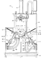
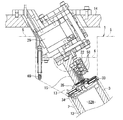
図1は、本発明に係るシリンダブロックめっき処理装置のシール構造における一実施の形態が適用されためっき処理装置として機能する処理装置を示す全体正面図である。図2は、図1の処理装置における電極及びエアジョイント周りを示す断面図である。 FIG. 1 is an overall front view showing a processing apparatus functioning as a plating apparatus to which an embodiment of a seal structure of a cylinder block plating apparatus according to the present invention is applied. FIG. 2 is a cross-sectional view showing the periphery of an electrode and an air joint in the processing apparatus of FIG.
図1に示す処理装置10は、エンジンにおけるシリンダブロック1のシリンダ内周面3の一端側であるクランクケース面5側端部をシール治具13(図2)がシールし、シリンダ内周面3に処理液(めっき前処理液またはめっき液)を導いて、シリンダ内周面3を高速で処理(めっき前処理またはめっき処理)するものであり、装置本体11、電極12、シール治具13、ワーク保持治具14、エアジョイント15、クランプ用シリンダ16及び電極用シリンダ17を有して構成される。
In the
本実施の形態では、シリンダブロック1がV型多気筒エンジンのV型シリンダブロックであり、このシリンダブロック1において所定角度差を有して形成された複数のシリンダ2のシリンダ内周面3に、処理装置10によって同時にめっき前処理またはめっき処理が施される。従って、処理装置10は、シリンダブロック1用の電解エッチング処理装置、陽極酸化処理装置等のシリンダブロックめっき前処理装置、及び/またはシリンダブロックめっき処理装置として機能する。
In the present embodiment, the
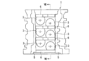
また、シリンダブロック1には、図6及び図7に示すように、複数のシリンダ2におけるシリンダ内周面3のクランクケース面5側端部付近に、クランクケースとの間でクランクシャフト(共に図示せず)を軸支するためのクランクジャーナル6が形成されている。複数のシリンダ2の配列ピッチが短く設定されたシリンダブロック1では、クランクジャーナル6は、シリンダ内周面3のクランクケース面5側端部付近において、シリンダ2の内側方向に張り出して形成され、シリンダ内周面3のクランクケース面5側端部付近において障害物となっている。
Further, as shown in FIGS. 6 and 7, the
図1に示すように、処理装置10の装置本体11は架台18に設置して固定され、シリンダブロック1を載置するワーク載置台19を備える。シリンダブロック1は、ヘッド面4を下方にしてワーク載置台19に載置される。装置本体11にはワーク載置台19の上方にワーク保持治具14が、クランプ用シリンダ16によって昇降可能に設置される。このワーク保持治具14には、図示しないクランプ(不図示)が設けられている。ワーク保持治具14は、下降位置で、ワーク載置台19に載置されたシリンダブロック1のクランクケース面5に当接する。このとき、ワーク保持治具14の前記クランプがシリンダブロック1のクランクケース面5側を把持して、シリンダブロック1がワーク載置台19とワーク保持治具14間に保持される。
As shown in FIG. 1, the apparatus
このときには、エアジョイント15は、図1の1点鎖線及び図3に示すように、シリンダブロック1のクランクケース面5側からシリンダブロック1内へ挿入され、電極12の上端に設置されたシール治具13に対向し、このシール治具13から離反した待機位置で待機する。
At this time, the
電極12は電極支持部20に支持され、この電極支持部20が装置本体11に設置された電極用シリンダ17に取り付けられる。この電極用シリンダ17の進退動作によって、電極12がシリンダブロック1のシリンダ2内へ、シリンダ内周面3のヘッド面4側端部から挿入され、また、電極12がシリンダブロック1のシリンダ2から退避される。図1の左側の電極12がシリンダ2内への挿入状態を示し、図1の右側の電極12がシリンダ2からの退避状態を示す。電極12がシリンダブロック1のシリンダ2内へ挿入されたときには、流路構成ブロック66に設置されたシリコンゴムシートなどのシールリング21(図2)がシリンダブロック1のヘッド面4に接触して、シリンダ内周面3のヘッド面4側端部(他端側)がシールされる。
The
尚、流路構成ブロック66は、電極支持部20に一体化されて、この電極支持部20及び電極12と共に電極用シリンダ17により動作され、且つ電極支持部20の外周面との間で処理液用の流路67を構成する。また、電極12内にも、処理液用の流路(電極内流路12A)が形成される。
The flow
図1〜図3に示すように、電極12の上端にシール治具13が設置され、ワーク保持治具14に、シール治具13のシール部材33を作動させる駆動機構としてのエアジョイント15が、シール治具13と分離して、このシール治具13及び電極12の上方位置に配置されている。
As shown in FIGS. 1 to 3, a
シール治具13は、電極12と共に、電極用シリンダ17の進出動作によって、シリンダ内周面3のヘッド面4側端部からシリンダ内へ挿入される。従って、シール治具13は、図3、図6及び図7に示すクランクジャーナル6を回避して挿入される必要がない。このため、シール治具13のシール部材33は、その外径寸法がシリンダ内周面3の内径寸法に近い値、即ちシリンダ内周面3の内径寸法よりも若干小さな値に設定されて、後述の拡張・収縮量が低減される。
The
エアジョイント15は、シール治具13のシール部材33を作動させるための作動流体としてのエアを、このシール部材33へ供給するものである。このエアジョイント15は、図4に示すように、ワーク保持治具14に固定されたエアジョイント用シリンダ29に設置されており、このエアジョイント用シリンダ29の進退動作によって、図2及び図4に示す進出位置と、図2の2点差線及び図3に示す待機位置との間で移動可能に設けられる。従って、このエアジョイント15は、エアジョイント用シリンダ29の進出動作によって、図3に示す待機位置からシリンダ2へ向かって移動され、図2及び図4に示すように、シリンダ2内に挿入されたシール治具13に結合可能に設けられる。
The
即ち、これらのシール治具13及びエアジョイント15は、電極12がシリンダブロック1のシリンダ2内へ挿入された後に、エアジョイント用シリンダ29の進出動作でエアジョイント15がシール治具13に当接して結合し、後に詳説するが、エアジョイント15のメインエア継手22からシール治具13のシール部材33へ流体としてのエア(空気)が供給される。これにより、シール部材33が半径方向のみに拡張してシリンダブロック1のシリンダ内周面3に接触し、このシリンダ内周面3のクランクケース面5側端部(一端側)がシールされる。シール部材33へのエアの供給が停止されてこのシール部材33が収縮した後に、エアジョイント15は、エアジョイント用シリンダ29の退避動作によって待機位置に戻される。
That is, the
ここで、エアジョイント15に設置されるメインエア継手22及び後述のサブエア継手58は、図3及び図4に示すように、シリンダブロック1のクランクジャーナル6を回避する位置に設けられ、クランクジャーナル6との干渉が防止される。尚、図4中の符号69は、処理中のシリンダブロック1の温度を測定するための温度センサであり、エアジョイント用シリンダ29に隣接してワーク保持治具14に設置される。
Here, as shown in FIGS. 3 and 4, the
図1に示す電極支持部20には処理液パイプ23Aが接続され、この処理液パイプ23Aに送液ポンプ24A(図2)が配設される。この送液ポンプ24Aは、シリンダブロック1のシリンダ内周面3におけるクランクケース面5側端部がシール部材33によりシールされた状態において、薬液貯留タンク25に貯溜された処理液(めっき液)を処理液パイプ23A及び電極支持部20を経て電極12の電極内流路12Aへ導く。この電極内流路12Aに導かれた処理液は、図2の矢印に示すように電極内流路12Aを上方へ流れ、シール治具13のシール下板34(後述)と電極12との間のスリット26を経て、電極12の外周面とシリンダブロック1のシリンダ内周面3とにより区画される空間27内を下方へ流れ、電極支持部20と流路構成ブロック66により構成される流路67を経て薬液貯留タンク25へ戻り循環する。
A
また、流路構成ブロック66に処理液パイプ23Bが接続され、この処理液パイプ23Bに送液ポンプ24Bが配設される。この送液ポンプ24Bは、シリンダブロック1のシリンダ内周面3におけるクランクケース面5側端部がシール治具13によりシールされた状態で、薬液タンク25に貯溜された処理液(めっき前処理液)を処理液パイプ23B、電極支持部20と流路構成ブロック66により構成される流路67を順次経て、電極12とシリンダ内周面3との空間27内へ導き、この空間27内を上方へ流動させる。この空間27内を流れた処理液は、シール治具13と電極12間のスリット26を通って電極12の電極内流路12Aへ至り、この電極内流路12Aを下方へ流れ、薬液タンク25へ戻って循環する。尚、処理液パイプ23A及び23Bは、屈曲自在なフレキシブルホースで構成されている。
Further, the processing
図1及び図2に示すように、電極支持部20には屈曲可能なリード線28が接続され、このリード線28が電源装置30に接続される。電源装置30は、前記空間27が処理液で満たされ、この処理液が流動した状態で、リード線28及び電極支持部20を経て電極12へ電気を供給する。この給電は、めっき前処理時には電極12がマイナス極、シリンダブロック1がプラス極になるように実施され、これによりシリンダブロック1のシリンダ内周面3がめっき前処理される。めっき処理時には電極12がプラス極、シリンダブロック1がマイナス極に給電され、シリンダ内周面3がめっき処理されて、このシリンダ内周面3にめっき皮膜が形成される。ここで、めっき前処理とめっき処理は、処理液と通電条件等を異ならせることで、同一種類の処理装置10により実施される。
As shown in FIGS. 1 and 2, a
尚、エアジョイント15は、図1に1個図示されているが、電極12の個数に対応した個数(つまり、シリンダブロック1におけるシリンダ2の個数)がワーク保持治具14に設置されている。また、図1中の符号31は、シリンダブロック1のシリンダ内周面3にめっき前処理またはめっき処理がなされて、電極12がシリンダブロック1から退避した後に進出して、シリンダブロック1のヘッド面4へ洗浄液を噴射し洗浄するときに用いられる洗浄シャッターである。
Although one air joint 15 is shown in FIG. 1, a number corresponding to the number of electrodes 12 (that is, the number of
次に、前記シール治具13とエアジョイント15などの構成を、図2及び図5を用いて詳説する。
Next, the configuration of the sealing
シール治具13は、シリンダブロック1のシリンダ内周面3を含む空間27内へ処理液を導く際に、シリンダ内周面3のクランクケース側端部に接触してこのシリンダ内周面3をシールするものであり、シール部材33、シール下板34及びシールベース35を有して構成される。
The
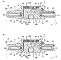
シール部材33は、図5に示すように、伸縮自在な材料(例えばゴムなどの弾性部材)にて構成され、浮き輪形状に形成される。このシール部材33の内周側部分は開口されて開口部49が設けられると共に、この開口部49近傍の両側に係合突起36が形成される。このシール部材33の外周部33Aが、シリンダブロック1のシリンダ内周面3に接触可能とされる。このシール部材33の外周部33Aの外径寸法は、内部にエアが供給されない状態で、シリンダ内周面3の内径寸法よりも若干小さな値に設定される。
As shown in FIG. 5, the
シール下板34は、図5に示すように、円板部32の中央に膨出部37が一体成形されて構成される。膨出部37の外周に、周溝38が形成されたリング部材39が配置される。また、膨出部37にはメインエア流路40C及び40Dが連通して形成される。このうちメインエア流路40Dは、シール下板34の周方向に複数本、例えば3本等間隔に形成される。このメインエア流路40Dは、リング部材39の周溝38に連通し、このリング部材39の周方向複数箇所(例えば3箇所)に周溝38に連通して形成されたメインエア流路40Eと連通する。
As shown in FIG. 5, the
また、シール下板34の円板部32には、膨出部37との境界部分に係合溝41がリング形状に形成される。この係合溝41に、シール部材33の係合突起36が係合される。また、円板部32及び膨出部37には、締結用の雌ねじ部42と、ボルト43挿入用のボルトねじ穴44が設けられる。このように構成されたシール下板34は、リング部材39にシール部材33の開口部49を嵌合させ、係合溝41にシール部材33の係合突起36が係合した状態で、円板部32がシール部材33の一方の片側面(図5の下側面33C)を支持する。
Further, an
シールベース35は、図5に示すように、円板部45の中央に膨出部46が一体成形されて構成され、膨出部46にシート座47及びメインエア流路40Bが形成される。シート座47にシールシート48が装着され、このシールシート48に、メインエア流路40Bに連通するメインエア流路40Aが形成される。メインエア流路40Bは、シール下板34のメインエア流路40Cに連通可能に設けられる。
As shown in FIG. 5, the
また、円板部45には、シート座47と反対位置に、シール下板34の膨出部37を嵌合可能な凹部50が形成され、この凹部50の外側に係合溝51がリング状に形成される。この係合溝51にシール部材33の係合突部36が係合される。円板部45及び膨出部46には、ボルト43螺挿用のボルトねじ穴52が形成される。
Further, the
シール下板34の膨出部37がシールベース35の凹部50に嵌合し、シール部材33の開口部49がシール下板34のリング部材39に嵌合し、シール部材33の係合突起36がシール下板34の係合溝41及びシールベース35の係合溝51に係合した状態で、シール下板34のボルトねじ穴44とシールベース35のボルトねじ穴52にボルト43が螺合され、シール部材33、シール下板34及びシールベース35が一体化されてシール治具13が構成される。
The bulging
この状態で、シール下板34とシールベース35とが互いに対向配置され、シール下板34の円板部32がシール部材33の一方の片側面(図5の下側面33C)を、シールベース35の円板部45がシール部材33の他方の片側面(図5の上側面33B)をそれぞれ支持する。更に、シール部材33、シール下板34及びシールベース35が一体化された状態で、互いに連通するメインエア流路40A、40B、40C、40D及び40Eが、シール部材33の内部に連通する。
In this state, the seal
図2に示すように、シール治具13は、絶縁部材としてのシール治具取付板53を介して電極12の上端に取り付けられる。このシール治具取付板53は4方向が切り欠かれた略十字形状に形成され、中央部に締結用の雄ねじ部54が形成される。この略十字形状のシール治具取付板53の先端部がボルト55により電極12に固定される。そして、シール治具取付板53の雄ねじ部54がシール治具13のシール下板34における雌ねじ部42に螺合して、シール部材33、シール下板34及びシールベース35が一体化されたシール治具13がシール治具取付板53に取り付けられる。
As shown in FIG. 2, the sealing
このシール治具取付板53は、非導電性の樹脂などにて構成され、導電性の金属にて構成されたシール下板34及びシールベース35を電極12に対して絶縁する。また、略十字形状のシール治具取付板53の切り欠かれた部分を通って処理液が、例えば図2の矢印に示すように前記スリット26へ向かって流動する。シール治具取付板53の外周側下面には、絶縁性を更に高めるために、絶縁カラー68が装着されている。
The seal
図1及び図2に示すエアジョイント15は、前述の如くメインエア継手22を備えると共に、メインエア供給流路56が形成されている。メインエア継手22は、メインエア供給配管57を介して図示しないエア供給バルブ及びコンプレッサに接続される。また、エアジョイント15は、電極12がシリンダブロック1のシリンダ2内に挿入された後に、エアジョイント用シリンダ29の進出動作によって、図3に示す待機位置からシリンダ2へ向かって挿入され、電極12に取り付けられたシール治具13のシールシート48に当接して、このシール治具13に結合する。この結合状態で、エアジョイント15のメインエア供給流路56がシール治具13のシールシート48のメインエア流路40Aに連通する。メインエア供給流路56からメインエア流路40Aへエアが供給されるが、この際のエアの漏洩がシールシート48により防止される。
The air joint 15 shown in FIGS. 1 and 2 includes the main air joint 22 as described above, and a main
このシールシート48は、エアの漏洩を防止する気密性確保の機能のほか、エアジョイント15の当接時の衝撃を吸収する機能も有する。このため、このシールシート48は、シリコンゴムやテフロン(登録商標)ゴムなどの弾性部材にて構成されることが好ましい。このシールシート48は、シール治具13のシールベース35に装着される代りに、エアジョイント15の先端に設けられてもよく、またはシール治具13のシールベース35とエアジョイント15の先端との両者に設けられてもよい。
The
メインエア供給流路56からメインエア流路40Aへ供給されたエアは、図5に示すように、メインエア流路40B、40C、40D及び40Eを経てシール部材33内へ導入される。このシール部材33は、上側面33Bがシールベース35により、下側面33Cがシール下板34によりそれぞれ支持されて膨張が規制されるので、図5(A)に示すように半径方向のみに拡張され、シール部材33の外周部33Aがシリンダブロック1のシリンダ内周面3に接触して、このシリンダ内周面3のクランクケース面5側端部をシールする。これにより、シリンダ内周面3と電極12の外周面とにより区画された空間27(図2)からクランクケース面5側へ、めっき前処理液またはめっき液が液漏れすることが防止される。
The air supplied from the main
メインエア継手22からシール部材33内へのエアの供給が遮断されたときには、図5(B)に示すように、シール部材33は半径方向に収縮して、その外周部33Aがシリンダ内周面3から離反する。その後、エアジョイント用シリンダ29の退避動作によって、エアジョイント15はシール治具13のシールシート48から離反し、待機位置(図3)に戻される。
When the supply of air from the
シール部材33の拡張、収縮を確認する確認手段が、図2に示すようにシール治具13及びエアジョイント15に設けられている。この確認手段は、エアジョイント15側のサブエア継手58及びサブエア供給流路59と、シール治具13側のサブエア流路60と、エア圧センサ61及び制御回路62とである。
Confirmation means for confirming expansion and contraction of the
サブエア継手58は、エアジョイント15に複数個、例えば3個配置されている。サブエア供給流路59は、サブエア継手58に対応してエアジョイント15に複数本、例えば3本形成され、それぞれがサブエア継手58に連通して設けられる。 A plurality of, for example, three sub air joints 58 are arranged in the air joint 15. A plurality of, for example, three sub air supply passages 59 are formed in the air joint 15 corresponding to the sub air joint 58, and each is provided in communication with the sub air joint 58.
サブエア流路60は、図5に示すように、シール治具13のシールベース35に形成される。このシールベース35には、膨出部46の天面に同心円状のリング溝63が、サブエア供給流路59の本数に対応して複数個(例えば3個)形成されており、それぞれが各サブエア供給流路59(図2)に連通可能とされる。シールベース35には、更に、各リング溝63の個数に対応して複数本(例えば3本)のサブエア流路60が放射状に等間隔に形成される。それぞれのサブエア流路60が各リング溝63に連通して設けられる。これらのサブエア流路60のそれぞれには、シールベース35の外周端部において吹出口64が形成される。この吹出口64は、図5に示すように、シール部材33の拡張時にこのシール部材33によって閉塞され、シール部材33の収縮時に開放される位置に設けられる。
The sub
図2に示すエアジョイント15に備えられたサブエア継手58から導入される流体としてのエアは、サブエア供給流路59を通り、シール治具13(図5)のリング溝63及びサブエア流路60を経て吹出口64から吹き出し可能に設けられる。この吹出口64からのエアの吹き出しは、図5(B)に示すように、シール部材33の収縮時に吹出口64がシール部材33により閉塞されず開放されているときに実施される。このときには、サブエア流路60、サブエア供給流路59及びサブエア継手58のエア圧が低くなる。これに対し、シール部材33の拡張時には、図5(A)に示すように、吹出口64がシール部材33により閉塞されてエアが吹出口64から吹き出されず、サブエア流路60、サブエア供給流路59及びサブエア継手58内のエア圧が上昇する。
Air as a fluid introduced from the sub air joint 58 provided in the air joint 15 shown in FIG. 2 passes through the sub air supply flow path 59 and passes through the
図2に示すエア圧センサ61は、例えば複数本のサブエア継手58へそれぞれエアを導く複数本、例えば3本のサブエア供給配管65に配置されて、上述のサブエア流路60のエア圧を検出する。このエア圧の検出値によって、シール治具13のシール部材33の拡張または収縮を確認することが可能となる。つまり、シール部材33が拡張してシリンダブロック1のシリンダ内周面3に接触し、このシリンダ内周面3を液密にシールしている状態であるか、またはシール部材33が収縮して、シリンダブロック1のシリンダ内周面3に接触せず、このシリンダ内周面3がシールされていない状態であるかを確認することが可能となる。
The
シール部材33の拡張、収縮によるシリンダブロック1のシリンダ内周面3のシールの確認は、サブエア流路60がシールベース35(つまりシール部材33)の周方向に複数本等間隔に、例えばシール部材33の周方向に120度の等間隔で3本形成されているので、シール部材33の全周に亘ってなされる。これにより、シール部材33の周方向の一部に劣化や亀裂、破損が発生して、その箇所以外ではシール部材33の拡張が正常になされるが、亀裂等が発生した箇所ではシール部材33の拡張が不充分となって、シリンダブロック1のシリンダ内周面3に接触していない場合にも、このシール部材33の周方向の拡張、収縮状況を確認して、シリンダ内周面3のシールを確認することが可能となる。
Confirmation of the seal of the cylinder inner
図2に示す制御回路62は、エア圧センサ61からの検出値を取り込んで、送液ポンプ24A、24B及び電源装置30の駆動を制御する。つまり、制御回路62は、エア圧センサ61からの検出値が所定値よりも高い場合に、シール治具13のシール部材33が拡張してシリンダブロック1のシリンダ内周面3に接触し、このシリンダ内周面3におけるクランクケース面5側のシールが良好になされていると判断する。このとき、制御回路62は、送液ポンプ24Aまたは24Bを起動して処理液を、シリンダ内周面3と電極12の外周面とにより区画された空間27へ供給し、その後、電源装置30を駆動して電極12へ給電し、シリンダ内周面3にめっき前処理(電解エッチング処理、陽極酸化処理)またはめっき処理を実施させる。
The
制御回路62は、エア圧センサ61からの検出値が所定値以下の場合には、シール治具13のシール部材33が適正に拡張せずまたは収縮して、シリンダ内周面3に接触していず、このシリンダ内周面3のシールが不完全であると判断して、送液ポンプ24A、24B及び電源装置30を駆動せず、またはこれらの駆動中にはこれらの駆動を中止する。
When the detected value from the
以上のように構成されたことから、本実施の形態によれば、次の効果(1)〜(3)を奏する。 With the configuration as described above, the following effects (1) to (3) are achieved according to the present embodiment.
(1)シリンダブロック1におけるシリンダ内周面3のクランクケース面5側端部をシールするシール治具13が、電極12の上端に設置され、このシール治具13のシール部材33をエアにより作動させるエアジョイント15が、シール治具13と分離してワーク保持治具14に配置され、シール治具13が電極12と共に、シリンダ内周面3のヘッド面4側端部からシリンダ2内へ挿入され、エアジョイント15がシリンダブロック1のクランクケース面5側からシリンダ2へ向かって挿入されて、シール治具13に結合される。
(1) A
このため、シリンダ内周面3のクランクケース面5側端部付近にクランクジャーナル6が障害物として存在する複雑な形状のシリンダブロック1であっても、シール治具13をシリンダ内周面3のヘッド面4側端部からシリンダ2内へ挿入するので、シール治具13におけるシール部材33は、クランクジャーナル6を回避する必要がなく、従って、その寸法をシリンダ内周面3の寸法に近い値に設定できる。このため、シール治具13におけるシール部材33の拡張・収縮量を低減できるので、シール治具13によるシール精度を確保でき、このシール治具13を用いてシリンダ内周面3を確実にシールできる。更に、シール部材33の拡張・収縮量を低減できるので、シール部材33の負担が少なく、その分シール部材33を長寿命化できる。
For this reason, even if the
(2)電極12に、処理液を流す電極内流路12Aが形成されると共に、この電極12を支持する電極支持部20と流路構成ブロック66との間にも、処理液を流す流路67が形成されている。そして、これらの電極12、電極支持部20及び流路構成ブロック66の上方に、シール治具13のシール部材33へ作動用のエアを供給するエアジョイント15及びエアジョイント用シリンダ29が配置されている。この結果、これらのエアジョイント15及びエアジョイント用シリンダ29は、処理液に接触することがないので、固着等のトラブルを防止できる。更に、エアシリンダ15及びエアジョイント用シリンダ29が電極内流路12Aや流路構成ブロック66の流路67の邪魔にならないので、これらの流路12A、67内で処理液の流れが乱されることがなく、この結果、シリンダブロック1のシリンダ内周面3のめっき品質を向上させることができる。
(2) An in-
(3)エアジョイント15は、シール治具13のシール部材33を作動させるエアを供給するものであるため、電動系を用いてシール部材33を動作させる場合に生ずる、処理液によるショートなどの不具合を確実に防止できる。
(3) Since the air joint 15 supplies air for operating the sealing
1 シリンダブロック
2 シリンダ
3 シリンダ内周面
4 ヘッド面(他端)
5 クランクケース面(一端)
6 クランクジャーナル
10 処理装置
12 電極
12A 電極内流路
13 シール治具
14 ワーク保持治具
15 エアジョイント(駆動機構)
33 シール部材
1
5 Crankcase surface (one end)
6
33 Seal member
Claims (6)
前記シール治具が電極の先端に設置され、このシール治具のシール部材を作動させる駆動機構が前記シール治具と分離して配置され、
前記電極及びシール治具が、前記シリンダ内周面の他端側から前記シリンダ内へ挿入され、前記駆動機構が前記一端側から挿入されて、前記シール治具と結合可能に構成されたことを特徴とするシリンダブロックめっき処理装置のシール構造。 A cylinder block plating apparatus that seals one end side of the cylinder inner peripheral surface of the cylinder in the cylinder block, guides the treatment liquid to the cylinder inner peripheral surface, and performs plating pretreatment or plating on the cylinder inner peripheral surface. Because
The sealing jig is installed at the tip of the electrode, and a drive mechanism for operating the sealing member of the sealing jig is arranged separately from the sealing jig,
The electrode and the sealing jig are inserted into the cylinder from the other end side of the inner peripheral surface of the cylinder, and the drive mechanism is inserted from the one end side so as to be coupled to the sealing jig. The seal structure of the cylinder block plating apparatus characterized by the above.
前記シリンダ内周面の他端側であるヘッド面側端部から電極及びシール治具がシリンダ内に挿入され、前記シリンダブロックのクランクケース面側から駆動機構が挿入されたことを特徴とする請求項1に記載のシリンダブロックめっき処理装置のシール構造。 In the cylinder block, a crank journal as an obstacle is formed to protrude in the cylinder inner direction in the vicinity of the end portion on the crankcase surface side which is one end side of the cylinder inner peripheral surface in the cylinder,
An electrode and a sealing jig are inserted into the cylinder from a head surface side end which is the other end side of the cylinder inner peripheral surface, and a drive mechanism is inserted from a crankcase surface side of the cylinder block. Item 2. A seal structure for a cylinder block plating apparatus according to Item 1.
Priority Applications (5)
| Application Number | Priority Date | Filing Date | Title |
|---|---|---|---|
| JP2008225262A JP5332416B2 (en) | 2008-09-02 | 2008-09-02 | Seal structure of cylinder block plating equipment |
| CN200980134931.8A CN102144051B (en) | 2008-09-02 | 2009-09-01 | Device for plating cylinder block and sealing mechanism therefor |
| DE112009002130.1T DE112009002130B4 (en) | 2008-09-02 | 2009-09-01 | Cylinder block metallizer and sealing mechanism for this |
| PCT/JP2009/065248 WO2010026958A1 (en) | 2008-09-02 | 2009-09-01 | Device for plating cylinder block and sealing mechanism therefor |
| US13/061,654 US8585876B2 (en) | 2008-09-02 | 2009-09-01 | Cylinder block plate processing apparatus and sealing mechanism of the same |
Applications Claiming Priority (1)
| Application Number | Priority Date | Filing Date | Title |
|---|---|---|---|
| JP2008225262A JP5332416B2 (en) | 2008-09-02 | 2008-09-02 | Seal structure of cylinder block plating equipment |
Publications (2)
| Publication Number | Publication Date |
|---|---|
| JP2010059457A true JP2010059457A (en) | 2010-03-18 |
| JP5332416B2 JP5332416B2 (en) | 2013-11-06 |
Family
ID=41797126
Family Applications (1)
| Application Number | Title | Priority Date | Filing Date |
|---|---|---|---|
| JP2008225262A Expired - Fee Related JP5332416B2 (en) | 2008-09-02 | 2008-09-02 | Seal structure of cylinder block plating equipment |
Country Status (5)
| Country | Link |
|---|---|
| US (1) | US8585876B2 (en) |
| JP (1) | JP5332416B2 (en) |
| CN (1) | CN102144051B (en) |
| DE (1) | DE112009002130B4 (en) |
| WO (1) | WO2010026958A1 (en) |
Cited By (1)
| Publication number | Priority date | Publication date | Assignee | Title |
|---|---|---|---|---|
| KR20200058967A (en) * | 2018-11-20 | 2020-05-28 | (주)동보 | Plating masking tool for common rail of a car |
Families Citing this family (3)
| Publication number | Priority date | Publication date | Assignee | Title |
|---|---|---|---|---|
| JP5338500B2 (en) * | 2009-06-10 | 2013-11-13 | スズキ株式会社 | Sealing jig and sealing method for cylinder block plating apparatus |
| DE102018110905A1 (en) * | 2018-05-07 | 2019-11-07 | Lucas Automotive Gmbh | Electrode for an anodizing process |
| CN111237464A (en) * | 2020-01-16 | 2020-06-05 | 中国科学院近代物理研究所 | Rotary dynamic sealing structure and rotary electrolytic polishing device |
Citations (2)
| Publication number | Priority date | Publication date | Assignee | Title |
|---|---|---|---|---|
| JPH07118891A (en) * | 1993-09-02 | 1995-05-09 | Yamaha Motor Co Ltd | Surface treating device |
| JP2000192287A (en) * | 1998-12-24 | 2000-07-11 | Suzuki Motor Corp | Surface treatment of cylinder block, masking method and device used for the same |
Family Cites Families (4)
| Publication number | Priority date | Publication date | Assignee | Title |
|---|---|---|---|---|
| US5620575A (en) * | 1993-12-27 | 1997-04-15 | Honda Giken Kogyo Kabushiki Kaisha | Composite plating apparatus and apparatus for dispersing air bubbles within a composite plating solution |
| JP3244962B2 (en) | 1994-09-05 | 2002-01-07 | ヤマハ発動機株式会社 | Surface treatment equipment |
| US5682676A (en) * | 1994-09-22 | 1997-11-04 | Yamaha Hatsudoki Kabushiki Kaisha | Method for surface treatment of work having plural cylinders with different axial alignments |
| JP3502689B2 (en) * | 1995-03-23 | 2004-03-02 | ヤマハ発動機株式会社 | Plating cylinder block and plating method thereof |
-
2008
- 2008-09-02 JP JP2008225262A patent/JP5332416B2/en not_active Expired - Fee Related
-
2009
- 2009-09-01 WO PCT/JP2009/065248 patent/WO2010026958A1/en active Application Filing
- 2009-09-01 CN CN200980134931.8A patent/CN102144051B/en not_active Expired - Fee Related
- 2009-09-01 DE DE112009002130.1T patent/DE112009002130B4/en not_active Expired - Fee Related
- 2009-09-01 US US13/061,654 patent/US8585876B2/en not_active Expired - Fee Related
Patent Citations (2)
| Publication number | Priority date | Publication date | Assignee | Title |
|---|---|---|---|---|
| JPH07118891A (en) * | 1993-09-02 | 1995-05-09 | Yamaha Motor Co Ltd | Surface treating device |
| JP2000192287A (en) * | 1998-12-24 | 2000-07-11 | Suzuki Motor Corp | Surface treatment of cylinder block, masking method and device used for the same |
Cited By (2)
| Publication number | Priority date | Publication date | Assignee | Title |
|---|---|---|---|---|
| KR20200058967A (en) * | 2018-11-20 | 2020-05-28 | (주)동보 | Plating masking tool for common rail of a car |
| KR102203342B1 (en) | 2018-11-20 | 2021-01-15 | (주)동보 | Plating masking tool for common rail of a car |
Also Published As
| Publication number | Publication date |
|---|---|
| US8585876B2 (en) | 2013-11-19 |
| US20110162961A1 (en) | 2011-07-07 |
| CN102144051A (en) | 2011-08-03 |
| CN102144051B (en) | 2015-01-21 |
| DE112009002130T5 (en) | 2011-06-22 |
| WO2010026958A1 (en) | 2010-03-11 |
| DE112009002130B4 (en) | 2016-12-22 |
| JP5332416B2 (en) | 2013-11-06 |
Similar Documents
| Publication | Publication Date | Title |
|---|---|---|
| JP5212184B2 (en) | Seal jig and plating equipment | |
| JP5168062B2 (en) | Cylinder block plating pretreatment apparatus and method | |
| JP5201004B2 (en) | Plating method | |
| JP5332416B2 (en) | Seal structure of cylinder block plating equipment | |
| CN106041999B (en) | The connection member of rat tail body is configured at the articulated robot of arm | |
| ES2795057T3 (en) | Hermetic surface processing machine and method | |
| CN1734140A (en) | Paint selector valve | |
| CN100569440C (en) | Fragment removal method and fragment are removed air nozzle | |
| JP2009270182A (en) | Plating treatment line | |
| JP5439767B2 (en) | Electrode structure of cylinder block surface treatment equipment | |
| TWI623652B (en) | Holding device and high-speed plating machine provided with the same | |
| TW201510292A (en) | Anode and high-speed plating device provided with same | |
| TW201510289A (en) | Power-supply member, and high-speed plating device provided with same | |
| JP5168081B2 (en) | Multi-cylinder cylinder block plating pretreatment apparatus and method | |
| CN104769339B (en) | For regulating the sealing device of valve | |
| JP5167986B2 (en) | Plating equipment | |
| CN113172332B (en) | Installation method, working method and system of liquid cooling friction stir welding tool clamping system | |
| KR20150106529A (en) | Tip for welding apparatus and the method thereof | |
| JP5338500B2 (en) | Sealing jig and sealing method for cylinder block plating apparatus | |
| JP3244962B2 (en) | Surface treatment equipment | |
| CN211626819U (en) | Water leakage detection device for aluminum shell in microwave product | |
| CN215318795U (en) | Manipulator with air passage | |
| CN218330446U (en) | Oil pump body gas tightness check out test set | |
| KR200387447Y1 (en) | Manifold | |
| JP6747649B1 (en) | Fluid module |
Legal Events
| Date | Code | Title | Description |
|---|---|---|---|
| A621 | Written request for application examination |
Free format text: JAPANESE INTERMEDIATE CODE: A621 Effective date: 20110523 |
|
| A131 | Notification of reasons for refusal |
Free format text: JAPANESE INTERMEDIATE CODE: A131 Effective date: 20130416 |
|
| A521 | Request for written amendment filed |
Free format text: JAPANESE INTERMEDIATE CODE: A523 Effective date: 20130607 |
|
| RD02 | Notification of acceptance of power of attorney |
Free format text: JAPANESE INTERMEDIATE CODE: A7422 Effective date: 20130607 |
|
| TRDD | Decision of grant or rejection written | ||
| A01 | Written decision to grant a patent or to grant a registration (utility model) |
Free format text: JAPANESE INTERMEDIATE CODE: A01 Effective date: 20130702 |
|
| A61 | First payment of annual fees (during grant procedure) |
Free format text: JAPANESE INTERMEDIATE CODE: A61 Effective date: 20130715 |
|
| LAPS | Cancellation because of no payment of annual fees |