JP2010058796A - Packaging case - Google Patents
Packaging case Download PDFInfo
- Publication number
- JP2010058796A JP2010058796A JP2008224579A JP2008224579A JP2010058796A JP 2010058796 A JP2010058796 A JP 2010058796A JP 2008224579 A JP2008224579 A JP 2008224579A JP 2008224579 A JP2008224579 A JP 2008224579A JP 2010058796 A JP2010058796 A JP 2010058796A
- Authority
- JP
- Japan
- Prior art keywords
- flap
- packaging case
- overlap
- folding
- folded
- Prior art date
- Legal status (The legal status is an assumption and is not a legal conclusion. Google has not performed a legal analysis and makes no representation as to the accuracy of the status listed.)
- Granted
Links
Images


Abstract
Description
この発明は、建築物に使用される木質フロア材等、長尺物の包装に適した包装ケースに関するものである。 The present invention relates to a packaging case suitable for packaging long objects such as wooden floor materials used in buildings.
従来、長尺の木質フロア材を包装する際には、図9に示すように、段ボール製の包装ケースとして、周壁51の長面及び幅面を形成する各一対の側板52,53を角筒状に折り曲げ、各側板52,53の上下から延びる短いフラップ54,55を内側へ折り曲げて、フロア材Fの外周部分を抱持するものを使用している。
Conventionally, when packaging a long wood floor material, as shown in FIG. 9, each pair of
この包装ケースは、ブランクが一方向に著しく長くなるのを防止するため、半分に分割した2枚の分割ブランク56から構成される。各分割ブランク56は、周壁51の2面を形成する側板52,53及びフラップ54,55を備え、側板53の一端に継代片57を連設したものとされている。
This packaging case is composed of two divided
そして、この包装ケースを製造する際には、分割ブランク56同士を、互いの継代片57を他の分割ブランク56の側板52の内面に貼り付けて継ぎ合わせる。このように分割ブランク56を継ぎ合わせると、フロア材Fの包装に際し、1枚のブランクから成る通常の包装ケースと同様に組み立てられる。
When the packaging case is manufactured, the divided
しかしながら、上記のような包装ケースでは、製造に際し、分割ブランク同士を手作業で糊貼りするため、加工コストが非常に高くつくという問題がある。 However, in the packaging case as described above, since the divided blanks are glued manually, there is a problem that the processing cost is very high.
そこで、この発明は、包装時の組立性を損なうことなく、低コストで製造できる包装ケースを提供することを課題とする。 Then, this invention makes it a subject to provide the packaging case which can be manufactured at low cost, without impairing the assembly property at the time of packaging.
上記のような課題を解決するため、この発明は、周壁の各面を形成する側板を角筒状に折り曲げ、各側板の上下から延びるフラップを内側へ折り曲げて、物品を包装する包装ケースにおいて、周壁の半分をなす側板及びフラップを備えた2本の列材が平行に並んだ1枚のブランクから構成し、このブランクは、各列材の相反する一端部に、折込部及び連結部を側板から順次連設し、各列材の連結部にフラップ重合部を設け、互いのフラップ重合部とフラップとを繋いで、列材同士を連結したものとし、互いの連結部が他の列材の内側に重なるように、列材同士を折り曲げ、折込部と連結部とを、その境界を谷折りして重ね合わせ、フラップをフラップ重合部と共に内側へ折り曲げたのである。 In order to solve the above problems, the present invention is a packaging case for packaging an article by folding side plates forming each surface of the peripheral wall into a rectangular tube shape, folding the flaps extending from the top and bottom of each side plate inward, It consists of one blank with two side plates with flaps and side plates forming half of the peripheral wall, and this blank has side plates with folding and connecting parts at opposite ends of each row material. Are connected to each other in sequence, provided with a flap overlapping portion at the connecting portion of each row material, connecting the flap overlapping portions and the flaps to each other, and connecting the row materials to each other. The row members were folded so as to overlap with each other, the folding portion and the connecting portion were overlapped with each other at the boundary, and the flap was folded inward together with the flap overlapping portion.
また、前記各列材の折込部にもフラップ重合部を設け、このフラップ重合部と連結部のフラップ重合部とを繋ぎ、折込部と連結部との谷折りに伴い、フラップ重合部同士が重なるようにしたのである。 In addition, a flap overlapping part is also provided in the folding part of each row material, the flap overlapping part and the flap overlapping part of the connecting part are connected, and the flap overlapping part overlaps with the valley folding of the folding part and the connecting part. I did it.
前記折込部のフラップ重合部の端縁と、これに隣り合うフラップの端縁とを、相互の干渉を回避するため、斜めに切り欠いたのである。 In order to avoid mutual interference, the edge of the flap overlapping part of the folding part and the edge of the flap adjacent thereto are cut out obliquely.
前記折込部及び連結部と、これに重なる側板及びフラップの端部とを、折り重ねた部分の反発を抑制するため、ブランクの厚さ方向に押し潰したのである。 In order to suppress the repulsion of the folded part, the folding part and the connecting part, and the side plate and the end part of the flap that overlap with each other are crushed in the thickness direction of the blank.
この発明に係る包装ケースでは、1枚のブランクを折り曲げて組み立てるので、製造時に糊貼りの手間がかかることなく、加工コストを抑制することができ、折込部と連結部とが重なり合うように予め折り曲げておくと、物品の包装に際し、従来の包装ケースと同様の作業で組み立てることができる。 In the packaging case according to the present invention, since one blank is folded and assembled, it is possible to suppress processing costs without taking time and effort to apply glue during manufacturing, and bend in advance so that the folded portion and the connecting portion overlap each other. In other words, when packaging an article, it can be assembled in the same manner as a conventional packaging case.
以下、この発明の実施形態を添付図面に基づいて説明する。 Embodiments of the present invention will be described below with reference to the accompanying drawings.
この発明に係る包装ケースは、図1に示す1枚の段ボール製ブランクから成り、図7に示す形状に組み立てて、長尺の木質フロア材Fを包装するものである。 The packaging case according to the present invention comprises a single cardboard blank shown in FIG. 1, and is assembled into the shape shown in FIG. 7 to wrap a long wooden floor material F.
このブランクでは、周壁1の半分を形成する長面及び幅面の側板2,3を横方向に連設し、側板2,3の上下にそれぞれフラップ4,5を連設した2本の列材11が平行に並べて配置されている。
In this blank,
各列材11の相反する一端部には、折込部6及び連結部7が側板3から順次連設されている。折込部6及び連結部7には、フラップ重合部6a,7aがそれぞれの上下に設けられ、隣接するフラップ重合部6a,7aは繋がれている。列材11同士は、互いのフラップ重合部7aとフラップ4とを繋いで連結されている。
A fold-in
折込部6のフラップ重合部6aと、これに隣り合うフラップ5の端部とは、組立時に折り曲げたとき、相互の干渉を防止するため、それぞれの先端から隣接する基端へかけて斜めに切り欠かれている。
The
折込部6と連結部7の境界には、罫線に沿って切目が入れられ、フラップ重合部6a,7aの基端にも、罫線に沿って切目が入れられている。また、側板2とフラップ4の境界にも、罫線に沿って断続するミシン目状の切目が入れられている。これらの切目は、組立時に折り曲げ易くするためのものである。
A cut is made along the ruled line at the boundary between the
また、図中斜線を施した折込部6及び連結部7と、連結部7が繋がる他の列材11の端部と、フラップ重合部6aに隣り合うフラップ5の端部とは、組立時に折り重ねた部分の反発を抑制するため、段ボールの厚さ方向に押し潰されている。
In addition, the folded
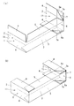
このようなブランクから包装ケースを組み立てるには、まず、図2及び図4(a)に示すように、各列材11の互いの連結部7が他の列材11の内側に重なるように、列材11同士を折り曲げる。
In order to assemble a packaging case from such a blank, first, as shown in FIG. 2 and FIG. 4 (a), the mutual connecting
次に、図3及び図4(b)に示すように、折込部6と連結部7とを、その境界を谷折りして重ね合わせ、これに伴い、フラップ重合部6a,7aを重ね合わせる。この状態で、包装ケースを保管しておくと、扁平な折畳状態となっているので、嵩張ることがない。
Next, as shown in FIG.3 and FIG.4 (b), the folding
そして、多数枚のフロア材Fを積み重ねて包装する際には、図5及び図8(a)に示すように、周壁1の各一対の側板2,3を角筒状に折り曲げる。
When a large number of floor materials F are stacked and packaged, the pair of
次に、図6、図7及び図8(b)に示すように、下方のフラップ5を内側へ折り曲げ、フラップ4をフラップ重合部6a,7aと共に内側へ折り曲げた状態で、周壁1の内部にフロア材Fを挿入した後、上方のフラップ5を内側へ折り曲げ、フラップ4をフラップ重合部6a,7aと共に内側へ折り曲げ、フラップ5に重ねて、バンド掛け等を施すと、包装が完了する。
Next, as shown in FIGS. 6, 7, and 8 (b), the
上記のような包装ケースでは、1枚のブランクを折り曲げて組み立てるので、従来の2枚のブランクを継ぎ合わせるもののように、製造時に糊貼りの手間がかかることなく、加工コストを抑制することができる。 In the packaging case as described above, since one blank is folded and assembled, the processing cost can be suppressed without taking time and effort for pasting the glue as in the case of joining two conventional blanks. .
また、図5に示すように、折込部6と連結部7とが重なり合うように予め折り曲げておくと、フロア材Fの包装に際し、従来の包装ケースと同様に、フラップ4,5を折り曲げるだけの作業で組み立てることができ、既存の包装機械を使用することもできる。
Also, as shown in FIG. 5, if the
なお、コーナー部分の強度に問題がない場合には、折込部6のフラップ重合部6aを省略してもよい。
In addition, when there is no problem in the strength of the corner portion, the
また、材料として、薄手の段ボールを使用する場合には、組立時の反発が弱いので、段ボールの押し潰しを省略してもよい。 Further, when thin cardboard is used as the material, the repulsion during assembly is weak, so that the cardboard may be omitted.
そのほか、上記実施形態では、周壁1が四角筒のものを例示したが、周壁1が六角筒や八角筒をなす包装ケースにおいても、同様の構成を採用することができる。
In addition, in the said embodiment, although the surrounding
1 周壁
2,3 側板
4,5 フラップ
6 折込部
7 連結部
6a,7a 重合部
11 列材
DESCRIPTION OF
Claims (4)
Priority Applications (1)
| Application Number | Priority Date | Filing Date | Title |
|---|---|---|---|
| JP2008224579A JP5021590B2 (en) | 2008-09-02 | 2008-09-02 | Packaging case |
Applications Claiming Priority (1)
| Application Number | Priority Date | Filing Date | Title |
|---|---|---|---|
| JP2008224579A JP5021590B2 (en) | 2008-09-02 | 2008-09-02 | Packaging case |
Publications (2)
| Publication Number | Publication Date |
|---|---|
| JP2010058796A true JP2010058796A (en) | 2010-03-18 |
| JP5021590B2 JP5021590B2 (en) | 2012-09-12 |
Family
ID=42186089
Family Applications (1)
| Application Number | Title | Priority Date | Filing Date |
|---|---|---|---|
| JP2008224579A Active JP5021590B2 (en) | 2008-09-02 | 2008-09-02 | Packaging case |
Country Status (1)
| Country | Link |
|---|---|
| JP (1) | JP5021590B2 (en) |
Cited By (1)
| Publication number | Priority date | Publication date | Assignee | Title |
|---|---|---|---|---|
| JP2014177297A (en) * | 2013-03-15 | 2014-09-25 | Tomoku Co Ltd | Package |
Citations (3)
| Publication number | Priority date | Publication date | Assignee | Title |
|---|---|---|---|---|
| JPS58183366U (en) * | 1982-05-29 | 1983-12-06 | 大日本印刷株式会社 | Shrink packaging with frame |
| JPS63156912U (en) * | 1987-03-31 | 1988-10-14 | ||
| JPH03187833A (en) * | 1989-09-12 | 1991-08-15 | Chiquita Brands Inc | Conainer capable of being piled up for ripening fuit during transport and storage |
-
2008
- 2008-09-02 JP JP2008224579A patent/JP5021590B2/en active Active
Patent Citations (3)
| Publication number | Priority date | Publication date | Assignee | Title |
|---|---|---|---|---|
| JPS58183366U (en) * | 1982-05-29 | 1983-12-06 | 大日本印刷株式会社 | Shrink packaging with frame |
| JPS63156912U (en) * | 1987-03-31 | 1988-10-14 | ||
| JPH03187833A (en) * | 1989-09-12 | 1991-08-15 | Chiquita Brands Inc | Conainer capable of being piled up for ripening fuit during transport and storage |
Cited By (1)
| Publication number | Priority date | Publication date | Assignee | Title |
|---|---|---|---|---|
| JP2014177297A (en) * | 2013-03-15 | 2014-09-25 | Tomoku Co Ltd | Package |
Also Published As
| Publication number | Publication date |
|---|---|
| JP5021590B2 (en) | 2012-09-12 |
Similar Documents
| Publication | Publication Date | Title |
|---|---|---|
| JP6863340B2 (en) | How to assemble the packaging box | |
| JP5021590B2 (en) | Packaging case | |
| JP7360302B2 (en) | Packaging box with polygonal partitions | |
| JP4727553B2 (en) | Cardboard tray | |
| JP2008254813A (en) | Polygonal packaging box | |
| WO2018198750A1 (en) | Packaging box | |
| JP3169848U (en) | Assembly box | |
| JP6907074B2 (en) | Packaging box | |
| TWI538858B (en) | Packaging box structure and method for folding the packaging box structure | |
| JP2013163537A (en) | Packaging box | |
| JP7475030B2 (en) | Packaging box and manufacturing method thereof | |
| JP4792264B2 (en) | paper box | |
| JP6988685B2 (en) | tray | |
| JP7155555B2 (en) | Self-supporting thin rectangular parallelepiped carton and manufacturing method thereof | |
| JP2004042969A (en) | Packaging box | |
| JP6003415B2 (en) | Mirror bowl container and method for assembling a mirror bowl set using the same | |
| JP5191344B2 (en) | One-touch partition structure | |
| TWM528967U (en) | Paper box structure | |
| JP3064784U (en) | Packaging box with pressure divider | |
| JPH07814U (en) | Packaging box | |
| JP2004359279A (en) | Packaging box | |
| JP2023177407A (en) | container | |
| JP3140382U (en) | Folding cardboard boxes | |
| JP2006044715A (en) | Packaging box | |
| JP2005219806A (en) | Prefabricated corrugated cardboard packaging box |
Legal Events
| Date | Code | Title | Description |
|---|---|---|---|
| A621 | Written request for application examination |
Free format text: JAPANESE INTERMEDIATE CODE: A621 Effective date: 20110407 |
|
| TRDD | Decision of grant or rejection written | ||
| A01 | Written decision to grant a patent or to grant a registration (utility model) |
Free format text: JAPANESE INTERMEDIATE CODE: A01 Effective date: 20120529 |
|
| A01 | Written decision to grant a patent or to grant a registration (utility model) |
Free format text: JAPANESE INTERMEDIATE CODE: A01 |
|
| A61 | First payment of annual fees (during grant procedure) |
Free format text: JAPANESE INTERMEDIATE CODE: A61 Effective date: 20120614 |
|
| R150 | Certificate of patent or registration of utility model |
Ref document number: 5021590 Country of ref document: JP Free format text: JAPANESE INTERMEDIATE CODE: R150 Free format text: JAPANESE INTERMEDIATE CODE: R150 |
|
| FPAY | Renewal fee payment (event date is renewal date of database) |
Free format text: PAYMENT UNTIL: 20150622 Year of fee payment: 3 |
|
| R250 | Receipt of annual fees |
Free format text: JAPANESE INTERMEDIATE CODE: R250 |
|
| R250 | Receipt of annual fees |
Free format text: JAPANESE INTERMEDIATE CODE: R250 |
|
| R250 | Receipt of annual fees |
Free format text: JAPANESE INTERMEDIATE CODE: R250 |
|
| R250 | Receipt of annual fees |
Free format text: JAPANESE INTERMEDIATE CODE: R250 |
|
| R250 | Receipt of annual fees |
Free format text: JAPANESE INTERMEDIATE CODE: R250 |
|
| R250 | Receipt of annual fees |
Free format text: JAPANESE INTERMEDIATE CODE: R250 |
|
| R250 | Receipt of annual fees |
Free format text: JAPANESE INTERMEDIATE CODE: R250 |
|
| R250 | Receipt of annual fees |
Free format text: JAPANESE INTERMEDIATE CODE: R250 |
|
| R250 | Receipt of annual fees |
Free format text: JAPANESE INTERMEDIATE CODE: R250 |