JP2010058741A - Turning controller for vessel propulsion engine - Google Patents
Turning controller for vessel propulsion engine Download PDFInfo
- Publication number
- JP2010058741A JP2010058741A JP2008228635A JP2008228635A JP2010058741A JP 2010058741 A JP2010058741 A JP 2010058741A JP 2008228635 A JP2008228635 A JP 2008228635A JP 2008228635 A JP2008228635 A JP 2008228635A JP 2010058741 A JP2010058741 A JP 2010058741A
- Authority
- JP
- Japan
- Prior art keywords
- servo
- turning
- signal
- control
- motor speed
- Prior art date
- Legal status (The legal status is an assumption and is not a legal conclusion. Google has not performed a legal analysis and makes no representation as to the accuracy of the status listed.)
- Granted
Links
Images


Abstract
Description
本発明は、Z型推進装置、L型推進装置やポッド推進装置のような推進機能と舵機能を備えたアジマススラスター等と総称される船舶推進機において、当該船舶推進機を旋回制御するための操舵システムである旋回制御装置に係り、特にACサーボモータによる電気式旋回制御装置に関するものである。 The present invention relates to a marine vessel propulsion device generally referred to as an azimuth thruster having a propulsion function and a rudder function such as a Z-type propulsion device, an L-type propulsion device, and a pod propulsion device. The present invention relates to a turning control device that is a steering system, and more particularly to an electric turning control device using an AC servo motor.
Z型推進装置やポッド推進装置等のアジマススラスターによる旋回では、従来は一般的に油圧旋回装置が使われていた。従来の油圧旋回装置は、油圧ポンプやサーボ弁、サクションフィルター、油タンク等の油圧機器の間が配管で接続された複雑な構成であり、オイル漏れによる汚損等もあり、不具合が生じる度に、修理や、オイルを充填してエアを取り除く等のメンテナンス作業が必要となるため、機器の安定的な運用に支障をきたす場合もあった。 Conventionally, a hydraulic swivel device is generally used for turning by an azimuth thruster such as a Z-type propulsion device or a pod propulsion device. The conventional hydraulic swivel device has a complicated structure in which hydraulic equipment such as a hydraulic pump, servo valve, suction filter, oil tank, etc. are connected by piping, and there is also contamination due to oil leakage, etc. Since repair work and maintenance work such as removing oil by filling with oil is required, stable operation of equipment may be hindered.
上述したような構成の複雑さやメンテナンス上の煩雑さを回避するため、油圧に替えて電気モータを使用することも考えられる。例えば、下記特許文献1は、アジマススラスタータイプではなく、通常の舵を制御するための技術に関するものであるが、モータを利用した電動式操舵装置の発明を開示している。しかしながら、そのモータはACモータ及びDCモータであり、サーボモータではない。従来、船舶のアジマススラスターの旋回制御用にサーボモータを使用した実例は存在していない。
本発明者等は、船舶のアジマススラスターの旋回制御用に、従来は用いられていなかったACサーボモータを利用する着想を得て、鋭意研究開発に務めた結果、従来知られていない新規な発明として(1) アナログ式、及び(2) マスタ・スレーブ通信方式の2種類の旋回制御装置を案出するに至った。
以下にこれらの装置について説明する。
As a result of diligent research and development, the present inventors have obtained an idea of using an AC servo motor that has not been conventionally used for turning control of a ship's azimuth thruster. As a result, we have devised two types of turning control devices: (1) analog type and (2) master / slave communication type.
These devices will be described below.
(1) アナログ式
図4に示すように、船舶推進機1は、船舶の底部外面に突出して旋回自在に設けられたケーシング2と、そのケーシング2に設けられ、図示しない主機に連結されて回転駆動されるプロペラ3とを備えている。そして、本例の旋回制御装置は、船舶推進機1の推進方向を任意に設定するために、船舶推進機1を所望の角度だけ旋回させて所望の旋回位置に設定するために利用される。この旋回制御装置を各構成部分ごとに説明する。
(1) Analog type As shown in FIG. 4, the ship propulsion device 1 is provided on the casing 2 so as to be pivotable by protruding from the outer surface of the bottom of the ship, and is connected to a main machine (not shown) and rotated. And a propeller 3 to be driven. The turning control device of this example is used to turn the ship propulsion device 1 by a desired angle and set it to a desired turning position in order to arbitrarily set the propulsion direction of the ship propulsion device 1. This turning control device will be described for each component.
操作ハンドル4は、船舶の乗組員が操作することにより、目標となる船舶推進機1の旋回位置を設定するための装置である。操作された操作ハンドル4からは、船舶推進機1の設定しようとする旋回位置を示すハンドル信号が出力される。
The
一方、船舶推進機1には、船舶推進機1の実際の旋回位置を検出してフィードバック信号を出力する角度センサ5が設けられている。
On the other hand, the marine vessel propulsion device 1 is provided with an
制御手段である旋回制御基板6では、操作ハンドル4が出力するハンドル信号と、角度センサ5からのフィードバック信号とがA/D変換器7でデジタル化され、両信号の偏差がCPU8で演算される。CPU8には、制御プログラム等が記憶されたROM9と、各種データが読み書きされるRAM10とを備えている。そして、CPU8は算出した偏差に応じてモータ速度指令を算出し、このモータ速度指令をD/A変換器11でアナログ化して外部に出力する。
In the turning control board 6 as the control means, the handle signal output from the
旋回制御基板6から出力されたアナログのモータ速度指令は、旋回制御基板6の外部に設けられた3基のACサーボアンプ12a,12b,12cにそれぞれ入力される。各ACサーボアンプ12a,12b,12cは、船舶推進機1の回転機構に取り付けられた3台のACサーボモータ15a,15b,15cに、モータ速度指令に対応した制御信号をそれぞれ与えるように接続構成されている。
The analog motor speed command output from the turning control board 6 is input to each of the three
各ACサーボアンプ12a,12b,12cには、当該ACサーボアンプ12a,12b,12cの異常を旋回制御基板6に通報するアラーム手段としてのアラームスイッチ18が設けられている。ACサーボアンプ12a,12b,12cに異常があった場合には、当該ACサーボアンプ12a,12b,12cのアラームスイッチ18が旋回制御基板6にアラーム(接点信号)を送り、これを受けた旋回制御基板6がサーボON/OFFスイッチ17で当該ACサーボアンプ12a,12b,12cを切り離して制御対象から外す。
Each
以上の構成によれば、旋回制御基板6のCPU8内部でハンドル信号とフィードバック信号の偏差が算出され、さらに該偏差からモータ指令信号が演算される。これをアナログ信号に変換して3つの各ACサーボアンプ12a,12b,12cに出力する。
According to the above configuration, the deviation between the steering wheel signal and the feedback signal is calculated inside the
しかしながら、このアナログ情報である同一のモータ指令信号を各ACサーボアンプ12a,12b,12cに与えた場合、その結果各ACサーボアンプ12a,12b,12cが対応する各ACサーボモータ15a,15b,15cに入力される制御信号にオフセットが生じることがある。これは、各ACサーボアンプ12a,12b,12cが有するアナログ信号を処理するためのICや抵抗器等の電子部品は、規格上は同一であっても性能値には各々固有のオフセットがあるため、同一のモータ指令信号を受けた場合であっても、ACサーボモータ15a,15b,15cに出力する制御信号が同一になるとは限らず、その制御信号には電圧のずれを生じることがあるからである。
However, when the same motor command signal as analog information is given to each
例えば、旋回制御基板6での偏差が0のとき、旋回制御基板6から各ACサーボアンプ12a,12b,12cには0(V)がモータ速度指令として与えられるが、この時、3台のACサーボアンプ12a,12b,12cのオフセットがすべて異なる場合がある。例えば、第1のACサーボアンプ12aは0(V)、第2のACサーボアンプ12bは+1(mV)、第3のACサーボアンプ12cは−3(mV)などどなる場合があり、この場合には第1のACサーボアンプ12aのACサーボモータ15aは停止、第2のACサーボアンプ12bのACサーボモータ15bは右回転、第3のACサーボアンプ12cのACサーボモータ15cは左回転などとなり、すなわち3台のACサーボモータ15a,15b,15cがそれぞればらばらに動作してしまう。
For example, when the deviation on the turning control board 6 is 0, 0 (V) is given as a motor speed command from the turning control board 6 to each of the
このようにオフセット値はアナログ入力ごと(ACサーボアンプごと)に異なり、オフセット値の極性の違いや大きさの差異により、特に微少偏差の場合等には目標位置付近で各ACサーボモータの回転速度や回転方向が異なって停止精度が十分にでない場合がある。このように、アナログ方式によれば、オフセットによる悪影響で船舶推進機1を目標の旋回位置に停止させる精度が低下するハンチングという現象を起こしてしまう問題があった。 In this way, the offset value differs for each analog input (for each AC servo amplifier), and due to the difference in polarity and size of the offset value, the rotational speed of each AC servo motor near the target position, especially in the case of a slight deviation. There are cases where the stopping accuracy is not sufficient due to different rotation directions. As described above, according to the analog method, there is a problem in that the phenomenon of hunting in which the accuracy of stopping the marine propulsion device 1 at the target turning position is lowered due to an adverse effect due to the offset occurs.
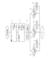
(2) マスタ・スレーブ通信方式
図5に示すように、船舶推進機1は、船舶の底部外面に突出して旋回自在に設けられたケーシング2と、そのケーシング2に設けられ、図示しない主機に連結されて回転駆動されるプロペラ3とを備えている。そして、本例の旋回制御装置は、船舶推進機1の推進方向を任意に設定するために、船舶推進機1を所望の角度だけ旋回させて所望の旋回位置に設定するために利用される。この旋回制御装置を各構成部分ごとに説明する。
(2) Master / Slave Communication Method As shown in FIG. 5, a ship propulsion device 1 is provided on a casing 2 that protrudes from the outer surface of the bottom of the ship so as to be turnable, and is connected to a main machine (not shown). And a propeller 3 that is driven to rotate. The turning control device of this example is used to turn the ship propulsion device 1 by a desired angle and set it to a desired turning position in order to arbitrarily set the propulsion direction of the ship propulsion device 1. This turning control device will be described for each component.
操作ハンドル4は、船舶の乗組員が操作することにより、目標となる船舶推進機1の旋回位置を設定するための装置である。操作された操作ハンドル4からは、船舶推進機1の設定しようとする旋回位置を示すハンドル信号が出力される。
The
一方、船舶推進機1には、船舶推進機1の実際の旋回位置を検出してフィードバック信号を出力する角度センサ5が設けられている。
On the other hand, the marine vessel propulsion device 1 is provided with an
制御手段である旋回制御基板16では、操作ハンドル4が出力するハンドル信号と、角度センサからのフィードバック信号とがA/D変換器7でデジタル化され、両信号の偏差がCPU8で演算される。CPU8は、制御プログラム等が記憶されたROM9と、各種データが読み書きされるRAM10とを備えている。そして、CPU8は算出した偏差に応じてモータ速度指令を算出し、このモータ速度指令を通信用ICであるシリアル信号生成部20でデジタル信号化し、ドライバ21を介して例えばRS422等のデジタル通信方式で外部に出力する。
In the
旋回制御基板16から出力されたデジタルのモータ速度指令は、旋回制御基板16の外部に設けられた3台のACサーボアンプ22a,22b,22cのうち、ACサーボアンプ22a(マスタ)のみに入力される。残りの2台のACサーボアンプはACサーボアンプ22b(スレーブ1)及びACサーボアンプ22c(スレーブ2)であり、ACサーボアンプ22a(マスタ)と同期をとってACサーボアンプ22a(マスタ)から通信でモータ速度指令の転送を受け、これによって3台のACサーボアンプ22a,22b,22cは対応する各ACサーボモータ15a,15b,15cに制御信号を送って制御を行なう。
The digital motor speed command output from the
各ACサーボアンプ22a,22b,22cには、当該ACサーボアンプ22a,22b,22cの異常を旋回制御基板16に通報するアラーム手段としてのアラームスイッチ18が設けられている。ACサーボアンプ22a,22b,22cに異常があった場合には、当該ACサーボアンプ22a,22b,22cのアラームスイッチ18が旋回制御基板16にアラーム(接点信号)を送り、これを受けた旋回制御基板16は異常があったACサーボアンプを切り離して制御対象から外す。
Each
以上の構成によれば、旋回制御基板16のCPU8内部でハンドル信号とフィードバック信号の偏差が算出され、さらに該偏差からモータ指令信号が演算される。これをデジタル信号に変換してドライバ21からACサーボアンプ22a(マスタ)にシリアル信号による通信方式で出力する。
According to the above configuration, the deviation between the steering wheel signal and the feedback signal is calculated in the
旋回制御基板16からモータ速度指令を送られたACサーボアンプ22a(マスタ)は、他の2台のACサーボアンプ22b,22c(スレーブ1、2)との間で同期をとり、対応する3台のACサーボモータ15a,15b,15cにそれぞれ制御信号を与えて制御する。
The
しかしながら、例えばACサーボアンプ22b(スレーブ1)だけが故障した場合には、その故障したACサーボアンプ22b(スレーブ1)だけを切り離せれば、ACサーボアンプ22a(マスタ)と残りのACサーボアンプ22c(スレーブ2)だけで制御可能であるが、ACサーボアンプ22a(マスタ)が故障した場合には、ACサーボアンプ22a(マスタ)が切り離されてしまうため、故障していないACサーボアンプ22b,22c(スレーブ1及び2)も制御できなくなり、全体として制御不能となってしまうという問題があった。
However, for example, when only the
このように、本発明者等は、ACサーボモータを利用したアジマススラスターの旋回制御装置(アナログ式及びマスタ・スレーブ通信方式)を発明したが、前述した通り、これらの発明にも解決すべき課題があることを見出した。そこで、本発明は、本発明者等による前述した新規な先行発明の課題を解決し、さらに改良された新たな発明を提供するものであり、アジマススラスターを旋回制御するためにACサーボモータを用いた旋回制御装置において、複数台のACサーボモータを1台から当該複数台まで独立して制御可能とすることにより制御不能に陥りにくく、小型から大型の旋回式船舶推進機1にまで広く適用可能であり、さらにアナログ式のようなオフセットの影響もなく高い追従精度が得られる船舶推進機1の旋回制御装置を提供することを目的としている。 As described above, the present inventors have invented the azimuth thruster turning control device (analog type and master / slave communication method) using an AC servo motor. However, as described above, these problems should also be solved. Found that there is. Accordingly, the present invention solves the problems of the above-mentioned novel prior invention by the present inventors and provides a new and improved invention, and uses an AC servo motor to control the turning of an azimuth thruster. In a conventional turning control device, it is possible to control a plurality of AC servo motors independently from one to the other, and thus it is difficult to fall out of control and can be widely applied to small to large turning type marine propulsion devices 1. In addition, an object of the present invention is to provide a turning control device for a marine propulsion device 1 that can obtain a high tracking accuracy without being affected by an offset like an analog type.
請求項1に記載された船舶推進機の旋回制御装置は、
回転駆動されるプロペラを備え推進方向を任意に設定するために船舶に旋回自在に設けられた船舶推進機を所望の旋回位置に設定する旋回制御装置において、
船舶推進機の旋回位置を設定することにより前記旋回位置を示すハンドル信号を出力する操作ハンドルと、
船舶推進機の旋回位置を検出してフィードバック信号を出力するセンサと、
前記操作ハンドルが出力するハンドル信号と前記センサからのフィードバック信号の偏差を演算し、該偏差に応じてモータ速度指令を演算し、前記モータ速度指令を複数の対象に対して同時に同一のデジタル信号としてデジタル通信によって送信する制御手段と、
前記制御手段から同時に同一のデジタル信号としてデジタル通信によって送信された前記モータ速度指令をそれぞれ受信し、前記モータ速度指令に応じて制御信号をそれぞれ出力する複数のACサーボアンプと、
前記各ACサーボアンプからの前記制御信号をそれぞれ受けて駆動されることにより船舶推進機1を旋回させる複数のACサーボモータと、
を具備することを特徴としている。
A turning control device for a ship propulsion unit according to claim 1 is provided.
In a turning control device for setting a ship propulsion device provided with a propeller that is rotationally driven and capable of turning freely on a ship to arbitrarily set a propulsion direction at a desired turning position,
An operation handle for outputting a handle signal indicating the turning position by setting a turning position of the ship propulsion device;
A sensor that detects the turning position of the ship propulsion device and outputs a feedback signal;
A deviation between a handle signal output from the operation handle and a feedback signal from the sensor is calculated, a motor speed command is calculated according to the deviation, and the motor speed command is simultaneously converted into the same digital signal for a plurality of objects. Control means for transmitting by digital communication;
A plurality of AC servo amplifiers each receiving the motor speed command transmitted by digital communication as the same digital signal simultaneously from the control means, and outputting a control signal according to the motor speed command;
A plurality of AC servo motors for turning the marine vessel propulsion machine 1 by being driven by receiving the control signals from the AC servo amplifiers;
It is characterized by comprising.
請求項2に記載された船舶推進機の旋回制御装置は、請求項1記載の船舶推進機の旋回制御装置において、
前記各ACサーボアンプには、当該ACサーボアンプの異常を前記制御手段にアラーム信号で通報するアラーム手段が設けられており、
前記制御手段はアラーム信号を受信した場合には、当該アラーム信号を出力した前記アラーム手段が設けられた前記ACサーボアンプを前記制御手段から切り離すことを特徴としている。
The turning control device for a ship propulsion device according to claim 2 is the turning control device for a ship propulsion device according to claim 1,
Each AC servo amplifier is provided with an alarm means for reporting an abnormality of the AC servo amplifier to the control means with an alarm signal.
When the control means receives an alarm signal, the control means disconnects the AC servo amplifier provided with the alarm means that outputs the alarm signal from the control means.
請求項1に記載された船舶推進機の旋回制御装置によれば、操作ハンドルからのハンドル信号とセンサからのフィードバック信号の偏差に基づいてモータ速度指令を演算し、このモータ速度指令を複数のACサーボアンプに対して同時に同一のデジタル信号としてデジタル通信によって送信するので、複数台のACサーボモータは、1台から全台数まで各々独立して制御可能であるため、仮に一部のACサーボアンプに故障が生じても装置全体としての制御不能には陥りにくい。また、複数のACサーボモータによる制御であるため、小型から大型の旋回式船舶推進機に広く適用可能であり、アナログ式のようなオフセットの影響もなく高い追従精度が得られる。 According to the turning control device for a marine vessel propulsion device described in claim 1, a motor speed command is calculated based on a deviation between a handle signal from the operation handle and a feedback signal from the sensor, and the motor speed command is converted into a plurality of AC speed commands. Since the same digital signal is simultaneously transmitted to the servo amplifier via digital communication, multiple AC servo motors can be controlled independently from one to all units. Even if a failure occurs, it is difficult for the entire device to fall out of control. In addition, since the control is performed by a plurality of AC servo motors, it can be widely applied to small to large turning type marine propulsion devices, and high follow-up accuracy can be obtained without the influence of offset as in the analog type.
請求項2に記載された船舶推進機の旋回制御装置によれば、請求項1記載の船舶推進機の旋回制御装置による効果において、さらに、ACサーボアンプが故障した場合には、当該ACサーボアンプのアラーム手段が異常を制御手段にアラーム信号で通報し、制御手段は異常が通報されたACサーボアンプのみを制御から切り離すことにより、残ったACサーボアンプとこれらに対応するACサーボモータだけで制御を継続することができる。 According to the turning control device for a ship propulsion device described in claim 2, in the effect of the turning control device for a ship propulsion device according to claim 1, when the AC servo amplifier further fails, the AC servo amplifier The alarm means reports the abnormality to the control means with an alarm signal, and the control means controls only the remaining AC servo amplifier and the corresponding AC servo motor by disconnecting only the AC servo amplifier in which the abnormality is reported from the control. Can continue.
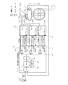
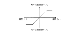
本発明の実施形態を図1〜図3を参照して説明する。図1は本発明の一実施形態である船舶推進機1の旋回制御装置を示す構成図であり、図2は一実施形態における旋回制御基板26での偏差とモータ速度指令の関係を示すグラフ図、図3は一実施形態における制御動作を示す流れ図である。
An embodiment of the present invention will be described with reference to FIGS. FIG. 1 is a configuration diagram showing a turning control device of a marine propulsion device 1 according to an embodiment of the present invention, and FIG. 2 is a graph showing a relationship between a deviation on a
図1に示すように、船舶推進機1は、船舶の底部外面に突出して旋回自在に設けられたケーシング2と、そのケーシング2に設けられ、図示しない主機に連結されて回転駆動されるプロペラ3とを備えている。そして、本例の旋回制御装置は、船舶推進機1の推進方向を任意に設定するために、船舶推進機1を所望の角度だけ旋回させて所望の旋回位置に設定するために利用される。以下、この旋回制御装置を各構成部分ごとに説明する。 As shown in FIG. 1, a marine vessel propulsion device 1 includes a casing 2 that protrudes from the outer surface of the bottom of the vessel and is provided so as to be rotatable, and a propeller 3 that is provided on the casing 2 and is driven to rotate by being connected to a main unit (not shown). And. The turning control device of this example is used to turn the ship propulsion device 1 by a desired angle and set it to a desired turning position in order to arbitrarily set the propulsion direction of the ship propulsion device 1. Hereinafter, this turning control device will be described for each component.
船舶の操舵室に設けられた操作ハンドル4は、船舶の乗組員が操作することにより、目標となる船舶推進機1の旋回位置を設定するための装置である。操作された操作ハンドル4からは、船舶推進機1の設定しようとする旋回位置を示すハンドル信号が出力される。
The operation handle 4 provided in the steering room of the ship is a device for setting a turning position of the target ship propulsion device 1 when operated by a crew member of the ship. From the operated
一方、船舶推進機1には、船舶推進機1の実際の旋回位置を検出してフィードバック信号を出力する角度センサ5が設けられている。
On the other hand, the marine vessel propulsion device 1 is provided with an
制御手段である旋回制御基板26では、操作ハンドル4が出力するハンドル信号と、センサからのフィードバック信号とがA/D変換器7でデジタル化され、両信号の偏差がCPU8で演算される。
In the turning
CPU8は、制御プログラムや制御に必要な各種データ、例えば図2に示すように前記偏差とモータ速度指令との関係を示すデータ等が記憶されたROM9aと、必要に応じて各種データが読み書きされるRAM10とを備えている。なお、図2に示すグラフが表すデータにおいて、モータ速度指令はモータ回転数とモータ回転速度を表す信号であり、前記偏差が+−いずれの極性においてもある限度以上に大きくなると、モータの最大能力を越えないように一定に維持されるようになっている(図2のグラフにおいて左右両端の水平部分を参照)。
The
CPU8は、算出した前記偏差とROM9aに格納した図2に示すようなデータを利用し、ROM9aの制御プログラムに従ってモータ速度指令を算出する。そして、このモータ速度指令は通信用ICであるシリアル信号生成部20(SIO)でデジタル信号化され、シリアル信号生成部20(SIO)に並列に接続された3つのドライバ21a,21b,21cを介して、RS422のデジタル通信方式で外部の3つのACサーボアンプ32a,32b,32cにそれぞれに出力される。
The
旋回制御基板26から出力されたデジタルのモータ速度指令は、旋回制御基板26の外部に設けられた3台のACサーボアンプ32a,32b,32cにそれぞれ入力されるが、これら3台のACサーボアンプ32a,32b,32cは互いに独立したアンプであって、モータ速度指令の送信を受け、これによって3台のACサーボアンプ32a,32b,32cは対応する各ACサーボモータ15a,15b,15cにそれぞれ制御信号を送って制御を行なう。
The digital motor speed command output from the turning
各ACサーボアンプ32a,32b,32cには、当該ACサーボアンプ32a,32b,32cの異常を旋回制御基板26に通報するアラーム手段としてのアラームスイッチ18が設けられている。ACサーボアンプ32a,32b,32cに異常があった場合には、当該ACサーボアンプ32a,32b,32cのアラームスイッチ18が旋回制御基板26にアラーム(接点信号)を送り、これを受けた旋回制御基板26は、各ACサーボアンプ32a,32b,32cごとに対応して設けられたサーボON/OFFスイッチ17を操作することにより、異常を通報してきたACサーボアンプ32a,32b,32cのみを通信系から切り離して制御対象から外す。
Each
次に、以上の構成における作用を図1及び図3を参照して説明する。
図3に示す本例の電気式旋回制御においては、まず旋回制御基板26のCPU8内部でハンドル信号とフィードバック信号の偏差が算出される(S1)。さらに偏差とモータ速度信号との関係を表すデータと、算出した前記偏差から、モータ指令信号が演算される(S2)。これをデジタル信号に変換してRS422の各ドライバ21a,21b,21cから対応する各ACサーボアンプ32a,32b,32cにデジタルのモータ速度指令を送信する(S3)。
Next, the operation of the above configuration will be described with reference to FIGS.
In the electric turning control of this example shown in FIG. 3, first, the deviation between the steering wheel signal and the feedback signal is calculated inside the
本例はアナログ制御ではなく、デジタルのモータ速度指令をACサーボアンプ32a,32b,32cに与えてACサーボモータ15a,15b,15cを制御するデジタル制御方式であるため、3台のACサーボモータ15a,15b,15cはばらばらに動作することはなく、同一の回転方向に同一の回転速度で動作して船舶推進機1を旋回させることができる。すなわちオフセットによる悪影響は存在せず、高い精度で船舶推進機1を目標の旋回位置に停止させることができ、目標値(所望の旋回位置)付近でハンチングを起こすことはない。一具体例を挙げれば、本発明者の先行発明であるアナログ制御の場合では目標値付近でハンチングし、位置決め誤差が収束しないが、本例によれば位置決め誤差は大きくみても±0.1度以内、ほとんど計測誤差の範囲内であり、誤差0といえる程度である。本例におけるこのような効果は、推進力が作用する方向自体を設定して保持する必要があるために回転方向の位置制御に高い精度が要求されるアジマススラスター等の船舶推進機1において、特に有利である。
This example is not an analog control but a digital control system in which a digital motor speed command is given to the
アナログ制御においては、特に微少偏差の場合等に目標位置付近で各ACサーボモータの回転速度や回転方向が異なって停止精度が十分にでない場合があったが、複数のACサーボモータ15a,15b,15cをそれぞれ独立してデジタル制御する本例によれば、ハンチングは確実に防止され、精密な回転位置制御が達成される。
In analog control, especially in the case of a slight deviation, the rotation speed and rotation direction of each AC servo motor is different near the target position, and stop accuracy may not be sufficient. However, a plurality of
図3に示す本例の電気式旋回制御において、ACサーボアンプ32a,32b,32cに異常があった場合(S4〜S6においてYES)には、当該ACサーボアンプ32a,32b,32cのアラームスイッチ18が旋回制御基板26にアラーム(接点信号)を送り、これを受けた旋回制御基板26は、各ACサーボアンプ32a,32b,32cごとに対応して設けられたサーボON/OFFスイッチ17を操作することにより、異常を通報してきたACサーボアンプ32a,32b,32cのみを通信系から切り離して制御対象から外す(S7〜S9)。異常がない場合は、S1からの制御手順を繰り返すこととなる。
In the electric turning control of the present example shown in FIG. 3, if there is an abnormality in the
このように、本例によれば、個々のACサーボアンプ32a,32b,32cはそれぞれ対応するACサーボモータ15a,15b,15cをそれぞれ独立して制御しているので、1基が故障しても全体として制御不能になるようなことはない。例えば、3台のACサーボモータ15a,15b,15cで運転している最中に、第1のACサーボモータ15aで故障が発生して第1のACサーボアンプ32aがアラームを発生すると、旋回制御基板26は第1のACサーボアンプ32aによる第1のACサーボモータ15aの運転をOFFとし、第1のACサーボモータ15aをフリーの状態(第1のACサーボモータ32aを切り離した状態)とする。ここで、第2及び第3のACサーボモータ15b,15cは正常であるため、通常のサーボ運転を継続する。このように、不具合が発生した場合は、不具合要因のみを切り離して正常なモータのみで運転を続行することができる。
As described above, according to this example, each
また、本例の電気式旋回制御において採用したACサーボモータは、周波数を変えてモータに与える電流値を制御し、トルクを制御することができるので、ある電流値(例えば10A)を限界としておけば、これに対応してトルクにもリミットがかかるため、これ以上の力が逆方向に加わっても船舶推進機1はこれ以上のトルクを発生して回転することはなく、外力に従って回るので機械の破損を防止することができる。すなわち、油圧におけるリリーフ機能と同様の機能をトルクリミット制御で達成することができる。 Also, the AC servo motor employed in the electric turning control of this example can control the current value applied to the motor by changing the frequency and control the torque, so that a certain current value (for example, 10 A) can be limited. For example, since torque is also limited in response to this, even if more force is applied in the opposite direction, the ship propulsion device 1 does not rotate by generating more torque but rotates according to the external force. Can be prevented from being damaged. That is, a function similar to the relief function in hydraulic pressure can be achieved by torque limit control.
また、本例の電気式旋回制御では複数のACサーボモータを使用しているので、一部のモータが故障その他で使用不能になっても、残りのモータで運転を続行でき、船舶運航上安全である。また、仮に1台のACサーボモータで必要な出力を得ようとすると相当の大きさになってしまうが、本例のように複数台(例えば本例のように3台程度)のモータに必要な出力を分担させた方が装置構成上無理がない。 In addition, since the electric swing control of this example uses multiple AC servo motors, even if some motors fail or cannot be used, the remaining motors can continue to operate, which is safe for ship operation. It is. Also, if it is attempted to obtain the required output with one AC servo motor, it will be a considerable size, but it is necessary for a plurality of motors (for example, about three as in this example) as in this example. It is not unreasonable for the device configuration to share a certain output.
1…船舶推進機
3…プロペラ
4…操作ハンドル
5…角度センサ
15a〜c…ACサーボモータ
17…サーボON/OFFスイッチ
18…アラーム手段としてのアラームスイッチ
21a〜c…ドライバ
26…制御手段としての旋回制御基板
32a〜c…ACサーボアンプ
DESCRIPTION OF SYMBOLS 1 ... Ship propulsion machine 3 ...
Claims (2)
船舶推進機の旋回位置を設定することにより前記旋回位置を示すハンドル信号を出力する操作ハンドルと、
船舶推進機の旋回位置を検出してフィードバック信号を出力するセンサと、
前記操作ハンドルが出力するハンドル信号と前記センサからのフィードバック信号の偏差を演算し、該偏差に応じてモータ速度指令を演算し、前記モータ速度指令を複数の対象に対して同時に同一のデジタル信号としてデジタル通信によって送信する制御手段と、
前記制御手段から同時に同一のデジタル信号としてデジタル通信によって送信された前記モータ速度指令をそれぞれ受信し、前記モータ速度指令に応じて制御信号をそれぞれ出力する複数のACサーボアンプと、
前記各ACサーボアンプからの前記制御信号をそれぞれ受けて駆動されることにより船舶推進機を旋回させる複数のACサーボモータと、
を具備することを特徴とする船舶推進機の旋回制御装置。 In a turning control device for setting a ship propulsion device provided with a propeller that is rotationally driven and capable of turning freely on a ship to arbitrarily set a propulsion direction at a desired turning position,
An operation handle for outputting a handle signal indicating the turning position by setting a turning position of the ship propulsion device;
A sensor for detecting a turning position of the ship propulsion device and outputting a feedback signal;
A deviation between a handle signal output from the operation handle and a feedback signal from the sensor is calculated, a motor speed command is calculated according to the deviation, and the motor speed command is simultaneously converted into the same digital signal for a plurality of objects. Control means for transmitting by digital communication;
A plurality of AC servo amplifiers each receiving the motor speed command transmitted by digital communication as the same digital signal simultaneously from the control means, and outputting a control signal according to the motor speed command;
A plurality of AC servomotors that turn the marine vessel propulsion machine by being driven by receiving the control signals from the AC servo amplifiers;
A turning control device for a marine vessel propulsion device.
前記制御手段はアラーム信号を受信した場合には、当該アラーム信号を出力した前記アラーム手段が設けられた前記ACサーボアンプを前記制御手段から切り離すことを特徴とする請求項1記載の船舶推進機の旋回制御装置。 Each AC servo amplifier is provided with an alarm means for reporting an abnormality of the AC servo amplifier to the control means with an alarm signal.
2. The ship propulsion device according to claim 1, wherein, when the control unit receives an alarm signal, the AC servo amplifier provided with the alarm unit that outputs the alarm signal is disconnected from the control unit. 3. Swivel control device.
Priority Applications (1)
| Application Number | Priority Date | Filing Date | Title |
|---|---|---|---|
| JP2008228635A JP5364318B2 (en) | 2008-09-05 | 2008-09-05 | Ship propulsion unit turning control device |
Applications Claiming Priority (1)
| Application Number | Priority Date | Filing Date | Title |
|---|---|---|---|
| JP2008228635A JP5364318B2 (en) | 2008-09-05 | 2008-09-05 | Ship propulsion unit turning control device |
Related Child Applications (1)
| Application Number | Title | Priority Date | Filing Date |
|---|---|---|---|
| JP2013108041A Division JP5636470B2 (en) | 2013-05-22 | 2013-05-22 | Ship propulsion unit turning control device |
Publications (2)
| Publication Number | Publication Date |
|---|---|
| JP2010058741A true JP2010058741A (en) | 2010-03-18 |
| JP5364318B2 JP5364318B2 (en) | 2013-12-11 |
Family
ID=42186045
Family Applications (1)
| Application Number | Title | Priority Date | Filing Date |
|---|---|---|---|
| JP2008228635A Active JP5364318B2 (en) | 2008-09-05 | 2008-09-05 | Ship propulsion unit turning control device |
Country Status (1)
| Country | Link |
|---|---|
| JP (1) | JP5364318B2 (en) |
Cited By (2)
| Publication number | Priority date | Publication date | Assignee | Title |
|---|---|---|---|---|
| WO2014054304A1 (en) | 2012-10-05 | 2014-04-10 | 新潟原動機株式会社 | Turning control device for ship propulsion device |
| JP2017171293A (en) * | 2017-06-05 | 2017-09-28 | 新潟原動機株式会社 | Turn control device of ship propulsion machine |
Citations (3)
| Publication number | Priority date | Publication date | Assignee | Title |
|---|---|---|---|---|
| JPH068190U (en) * | 1992-07-08 | 1994-02-01 | 川崎重工業株式会社 | Revolving thruster drive device |
| JPH07215292A (en) * | 1994-02-04 | 1995-08-15 | Mitsubishi Heavy Ind Ltd | Vehicle with oscillating blade control propeller |
| JP2008018882A (en) * | 2006-07-14 | 2008-01-31 | Honda Motor Co Ltd | Conversion unit of outboard motor |
-
2008
- 2008-09-05 JP JP2008228635A patent/JP5364318B2/en active Active
Patent Citations (3)
| Publication number | Priority date | Publication date | Assignee | Title |
|---|---|---|---|---|
| JPH068190U (en) * | 1992-07-08 | 1994-02-01 | 川崎重工業株式会社 | Revolving thruster drive device |
| JPH07215292A (en) * | 1994-02-04 | 1995-08-15 | Mitsubishi Heavy Ind Ltd | Vehicle with oscillating blade control propeller |
| JP2008018882A (en) * | 2006-07-14 | 2008-01-31 | Honda Motor Co Ltd | Conversion unit of outboard motor |
Cited By (5)
| Publication number | Priority date | Publication date | Assignee | Title |
|---|---|---|---|---|
| WO2014054304A1 (en) | 2012-10-05 | 2014-04-10 | 新潟原動機株式会社 | Turning control device for ship propulsion device |
| JP2014073783A (en) * | 2012-10-05 | 2014-04-24 | Niigata Power Systems Co Ltd | Turn control device of ship propulsion machine |
| EP2905219A1 (en) * | 2012-10-05 | 2015-08-12 | Niigata Power Systems Co., Ltd. | Turning control device for ship propulsion device |
| EP2905219A4 (en) * | 2012-10-05 | 2016-07-13 | Niigata Power Systems Co Ltd | Turning control device for ship propulsion device |
| JP2017171293A (en) * | 2017-06-05 | 2017-09-28 | 新潟原動機株式会社 | Turn control device of ship propulsion machine |
Also Published As
| Publication number | Publication date |
|---|---|
| JP5364318B2 (en) | 2013-12-11 |
Similar Documents
| Publication | Publication Date | Title |
|---|---|---|
| JP6312108B2 (en) | Ship station maintenance system and method | |
| EP3148752B1 (en) | Systems and methods for modular units in electro-mechanical systems | |
| AU2005293163B2 (en) | System of automatic control of maneuver of motor crafts, related method, and craft provided with the system | |
| EP3099570B1 (en) | Hydraulic slip compensation systems and methods | |
| CN108482631B (en) | Control system and control method for multiple full-turning rudder propellers | |
| US9376198B2 (en) | Serviceable marine pod steering brake system | |
| EP3432464B1 (en) | Multiaxial motor control system | |
| NO322007B1 (en) | Method and system for testing a dynamic positioning system | |
| US9868501B1 (en) | Method and system for controlling propulsion of a marine vessel | |
| JP2007253638A (en) | Remote controlling device, and water craft | |
| CN108100030A (en) | The method and system of steering wheel angle verification are realized based on EPS | |
| JP5364318B2 (en) | Ship propulsion unit turning control device | |
| US9963214B2 (en) | Ship handling device | |
| JP5636470B2 (en) | Ship propulsion unit turning control device | |
| WO2014017401A1 (en) | Steering device for ship | |
| JP6395996B2 (en) | Ship propulsion unit turning control device | |
| CN108508873A (en) | The submarine rudder system fault diagnosis and fault tolerant control method of ultrasonic wave auxiliary detection | |
| JP6419897B2 (en) | Ship propulsion unit turning control device | |
| JP5058721B2 (en) | Ship propulsion unit turning control device | |
| Kurowski et al. | AGaPaS-a new approach for Search-and-Rescue-Operations at sea | |
| JP2013184537A (en) | Actuator drive device | |
| JP2010000973A (en) | Electric motor driving system for vessel | |
| Benetazzo et al. | Fault-tolerant variable structure control of an overactuated dynamic positioning vessel after thruster failures | |
| US20230166823A1 (en) | Steering system with twin actuators and tie bar | |
| US10994822B1 (en) | Marine steering system and method providing resistance control |
Legal Events
| Date | Code | Title | Description |
|---|---|---|---|
| A621 | Written request for application examination |
Free format text: JAPANESE INTERMEDIATE CODE: A621 Effective date: 20110516 |
|
| A977 | Report on retrieval |
Free format text: JAPANESE INTERMEDIATE CODE: A971007 Effective date: 20120620 |
|
| A131 | Notification of reasons for refusal |
Free format text: JAPANESE INTERMEDIATE CODE: A131 Effective date: 20120724 |
|
| A521 | Request for written amendment filed |
Free format text: JAPANESE INTERMEDIATE CODE: A523 Effective date: 20120913 |
|
| A131 | Notification of reasons for refusal |
Free format text: JAPANESE INTERMEDIATE CODE: A131 Effective date: 20130326 |
|
| A521 | Request for written amendment filed |
Free format text: JAPANESE INTERMEDIATE CODE: A523 Effective date: 20130522 |
|
| TRDD | Decision of grant or rejection written | ||
| A01 | Written decision to grant a patent or to grant a registration (utility model) |
Free format text: JAPANESE INTERMEDIATE CODE: A01 Effective date: 20130813 |
|
| A61 | First payment of annual fees (during grant procedure) |
Free format text: JAPANESE INTERMEDIATE CODE: A61 Effective date: 20130909 |
|
| R150 | Certificate of patent or registration of utility model |
Ref document number: 5364318 Country of ref document: JP Free format text: JAPANESE INTERMEDIATE CODE: R150 Free format text: JAPANESE INTERMEDIATE CODE: R150 |
|
| S533 | Written request for registration of change of name |
Free format text: JAPANESE INTERMEDIATE CODE: R313533 |
|
| R350 | Written notification of registration of transfer |
Free format text: JAPANESE INTERMEDIATE CODE: R350 |
|
| R250 | Receipt of annual fees |
Free format text: JAPANESE INTERMEDIATE CODE: R250 |
|
| R250 | Receipt of annual fees |
Free format text: JAPANESE INTERMEDIATE CODE: R250 |
|
| R250 | Receipt of annual fees |
Free format text: JAPANESE INTERMEDIATE CODE: R250 |
|
| R250 | Receipt of annual fees |
Free format text: JAPANESE INTERMEDIATE CODE: R250 |