JP2010056656A - Display position decision device, display position decision method, and computer program - Google Patents
Display position decision device, display position decision method, and computer program Download PDFInfo
- Publication number
- JP2010056656A JP2010056656A JP2008216965A JP2008216965A JP2010056656A JP 2010056656 A JP2010056656 A JP 2010056656A JP 2008216965 A JP2008216965 A JP 2008216965A JP 2008216965 A JP2008216965 A JP 2008216965A JP 2010056656 A JP2010056656 A JP 2010056656A
- Authority
- JP
- Japan
- Prior art keywords
- display position
- transmission
- location
- display
- data
- Prior art date
- Legal status (The legal status is an assumption and is not a legal conclusion. Google has not performed a legal analysis and makes no representation as to the accuracy of the status listed.)
- Granted
Links
Images


Abstract
Description
本発明は、コンピュータなどの表示画面に通信ネットワークの構成を表示する際の表示方法に関する。 The present invention relates to a display method for displaying a configuration of a communication network on a display screen of a computer or the like.
ネットワークのバックボーンを構成する伝送システムは、通信ネットワークシステムを構成する伝送装置と、これらの伝送装置を含むネットワーク構成要素(NE: Network Element)を監視及び制御する監視制御装置(NE-OpS: NE Opetations System)とを含む。
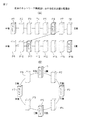
OpSと接続されるNEには、NE−OpSサーバと専用線などの通信回線を経由して接続される装置(GNE: Gateway NE)と、GNE経由で伝送装置の主信号に含まれるDCC(Data Communication Channel)を経由して接続される装置(RNE: Remote NE)とが含まれる。従来の伝送システムは、提供するサービスに応じて図1の(A)に示すリニア構成や図1の(B)に示すリング構成によりネットワークを構成していた。
A transmission system that constitutes the backbone of a network includes a transmission control device (NE-OpS: NE Opetations) that monitors and controls a transmission device that constitutes a communication network system and a network element (NE: Network Element) that includes these transmission devices. System).
The NE connected to the OpS includes a device (GNE: Gateway NE) connected to the NE-OpS server via a communication line such as a dedicated line, and a DCC (Data included in the main signal of the transmission device via the GNE. And devices connected via the Communication Channel (RNE: Remote NE). In the conventional transmission system, a network is configured with a linear configuration shown in FIG. 1A or a ring configuration shown in FIG.
リニア構成は、直線的に伝送装置NE1〜NE4を接続したネットワークの両端にGNEを配置し、NE−OpSサーバから2つのGNE経由で接続することによって、途中の接続が1箇所で切断された場合にも、全ての伝送装置がどちらか一方の端のGNEから監視及び制御されることが可能なネットワーク構成である。
リング構成は、リング状に伝送装置NE1〜NE4を接続することによって、冗長化を図ったネットワーク構成である。
In the linear configuration, the GNE is arranged at both ends of the network in which the transmission devices NE1 to NE4 are linearly connected, and the connection in the middle is disconnected at one location by connecting from the NE-OpS server via the two GNEs. In addition, in this network configuration, all transmission apparatuses can be monitored and controlled from the GNE at either end.
The ring configuration is a network configuration in which redundancy is achieved by connecting the transmission devices NE1 to NE4 in a ring shape.
近年、加入者線のブロードバンド化とIPサービスの増加により、キャリアネットワークのトラフィック量が急激に増加している。この状況に対応すべく、ネットワークのバックボーンを形成する伝送システムにおいても伝送装置の大容量化を図ってきたが、上記のリニア構成やリング構成のネットワークでは限界があった。このため、より効率的なネットワーク管理を行うためにメッシュ構成のネットワークの運用が近年求められている。メッシュ構成ネットワークでは、リニア構成ネットワークやリング構成ネットワークと違い、1つの伝送装置は、隣接する3つ以上の伝送装置と接続することが可能となる。 In recent years, the amount of traffic on carrier networks has increased rapidly due to the increase in subscriber line broadband and IP services. In order to cope with this situation, the transmission system that forms the backbone of the network has also been increased in capacity of the transmission device, but there are limitations in the network of the linear configuration and the ring configuration described above. For this reason, in order to perform more efficient network management, operation of a network having a mesh structure has been demanded in recent years. In a mesh configuration network, unlike a linear configuration network or a ring configuration network, one transmission device can be connected to three or more adjacent transmission devices.
OpSにおいて、ユーザインタフェースの表示画面上にネットワーク構成を表示する場合、ネットワークを構成する伝送装置を表示画面上の何れの位置に表示するかを決定する必要がある。リニア構成及びリング構成のネットワークを表示する場合には、各伝送装置が直列、またはリング状に接続されているため、各装置間の間隔が均等になるように自動配置すれば十分であった。 In OpS, when the network configuration is displayed on the display screen of the user interface, it is necessary to determine at which position on the display screen the transmission apparatus constituting the network is displayed. When displaying a network having a linear configuration and a ring configuration, since each transmission device is connected in series or in a ring shape, it is sufficient to automatically arrange the intervals between the devices to be equal.
図2の(A)はリニア構成のネットワークを表示する際の伝送装置の配置例を示す図である。本配置例では、最大16台の伝送装置を表示する位置P1〜P16が予め用意され、これらの位置P1〜P16に4台の伝送装置NE1〜NE4をできるだけ等間隔に配置する。
図2の(B)はリング構成のネットワークを表示する際の伝送装置の配置例を示す図である。本配置例では、最大8台の伝送装置を表示する位置P1〜P8が予め用意され、これらの位置P1〜P8に4台の伝送装置NE1〜NE4をできるだけ等間隔に配置する。
FIG. 2A is a diagram illustrating an arrangement example of transmission apparatuses when a network having a linear configuration is displayed. In this arrangement example, positions P1 to P16 for displaying a maximum of 16 transmission apparatuses are prepared in advance, and the four transmission apparatuses NE1 to NE4 are arranged at equal intervals as possible in these positions P1 to P16.
FIG. 2B is a diagram illustrating an arrangement example of transmission apparatuses when a network having a ring configuration is displayed. In this arrangement example, positions P1 to P8 for displaying a maximum of eight transmission apparatuses are prepared in advance, and four transmission apparatuses NE1 to NE4 are arranged at equal intervals as possible at these positions P1 to P8.
これに対して、メッシュ構成のネットワークでは、1つの装置が3つ以上の装置へ接続されることがあり、直列的な接続関係でネットワークを表現することができない。このため上記のような等間隔な伝送装置の配置による自動配置方法が使用できず、各伝送装置の多次元的な位置情報を用いることが必要となる。 On the other hand, in a mesh configuration network, one device may be connected to three or more devices, and the network cannot be expressed in a serial connection relationship. For this reason, it is not possible to use the automatic arrangement method based on the arrangement of the transmission devices at equal intervals as described above, and it is necessary to use multidimensional position information of each transmission device.
なお、下記特許文献1には、ノードA、B、Cと、ノード間を結ぶアークp、q、rとを有するネットワーク図形を描画するための情報を記憶するメモリが、ノードの位置情報と、アークの始点及び終点の位置情報と、アークがその始点及び終点で接するノードを特定する識別子と、を有するネットワーク図形半自動編集装置が開示されている。
In
複数の伝送装置と、伝送装置間を接続する伝送路とを表示して、ネットワークの全体構成を表示するとき、ネットワークがリニア構成、またはリング構成である場合に比べ、ネットワークがメッシュ構成の場合は、伝送装置の表示における配置の自由度が大きく、簡単なアルゴリズムで自動的にネットワーク構成を表示する方法が必要である。 When displaying the entire network configuration by displaying multiple transmission devices and transmission paths connecting the transmission devices, the network is a mesh configuration compared to a linear configuration or a ring configuration. Therefore, there is a need for a method of automatically displaying a network configuration with a simple algorithm with a large degree of freedom in arrangement in display of a transmission apparatus.
また、ネットワーク表示画面における伝送装置の表示位置として、その伝送装置が収容される局舎の位置情報すなわち所在地の位置情報を用い、伝送装置の表示位置を所在地の位置情報に関連付けられて決定することが考えられる。
この場合、1つの局舎内に複数の伝送装置が設置されていた場合に、所在地の位置情報のみに基づいて伝送装置の表示位置を決定すると、これらの伝送装置が表示画面上の同一位置に重なって表示されてしまい、これら複数の伝送装置とその接続関係を正しく表示できない場合がある。
Further, as the display position of the transmission apparatus on the network display screen, the position information of the station where the transmission apparatus is accommodated, that is, the position information of the location is used, and the display position of the transmission apparatus is determined in association with the position information of the location. Can be considered.
In this case, when a plurality of transmission apparatuses are installed in one station, if the display position of the transmission apparatus is determined based only on the location information, these transmission apparatuses are located at the same position on the display screen. In some cases, these multiple transmission devices and their connection relations cannot be displayed correctly.
開示のシステム及び方法は、メッシュ構成のネットワークを表示する際の上述の問題点を解消することを目的とする。 It is an object of the disclosed system and method to solve the above-described problems in displaying a mesh configuration network.
開示の装置、方法及びプログラムは、通信ネットワークを構成する伝送装置同士の接続関係を記憶する接続関係データの中から、当該伝送装置に接続する伝送装置である各隣接装置を決定し、通信ネットワークを表示する所定の表示画面上における各伝送装置の表示位置を記憶する表示位置データの中から、隣接装置の各々の隣接装置の表示位置を取得する表示位置取得し、取得された各々の表示位置の中間位置を伝送装置の表示位置として決定する。 The disclosed device, method, and program determine each adjacent device that is a transmission device connected to the transmission device from the connection relationship data that stores the connection relationship between the transmission devices that constitute the communication network. From the display position data for storing the display position of each transmission device on a predetermined display screen to be displayed, the display position for acquiring the display position of each adjacent device of the adjacent device is acquired, and each of the acquired display positions is acquired. The intermediate position is determined as the display position of the transmission apparatus.
また、開示の装置、方法及びプログラムは、各伝送装置が設置される所在地の候補の各々について各所在地の表示画面上の位置を示す位置情報がそれぞれ登録された所在地情報データの中から、表示位置決定部が決定した当該伝送装置の表示位置に最も近い所在地を検索し、この所在地の位置に伝送装置の表示位置を再配置する。 In addition, the disclosed apparatus, method, and program provide the display position from the location information data in which the location information indicating the location on the display screen of each location is registered for each of the location candidates where each transmission device is installed. The location closest to the display position of the transmission device determined by the determination unit is searched, and the display position of the transmission device is rearranged at the location of this location.
さらに、開示の装置、方法及びプログラムは、隣接装置の位置の中間値に基づき決定された伝送装置の表示位置と伝送装置について検索された所在地の位置との間の距離が所定値よりも大きいとき、各住所について表示画面上の位置を示す位置情報が登録された住所情報データの中から、伝送装置の表示位置に最も近い住所を検索し、この住所の位置情報と同じ位置情報を有する新たな所在地データを所在地情報データに登録し、新たに登録された所在地データの位置に伝送装置の表示位置を再配置する。 Furthermore, the disclosed apparatus, method, and program are configured such that the distance between the display position of the transmission apparatus determined based on the intermediate value of the position of the adjacent apparatus and the position of the location searched for the transmission apparatus is greater than a predetermined value. The address closest to the display position of the transmission device is searched from the address information data in which the position information indicating the position on the display screen is registered for each address, and a new one having the same position information as the position information of this address The location data is registered in the location information data, and the display position of the transmission apparatus is rearranged at the location of the newly registered location data.
またさらに、開示の装置、方法及びプログラムは、同一位置に再配置された複数の前記伝送装置のそれぞれについて、該伝送装置に接続する伝送装置である各隣接装置であって前記同一位置に配置されていないものとの間の表示位置の座標値の差の合計値を決定し、各伝送装置について決定したそれぞれの合計値に応じて、伝送装置の表示位置を、上記の同一位置に設けられた複数のマス目の位置のいずれかになるように調整する。 Still further, the disclosed apparatus, method, and program are arranged in the same position for each of the plurality of transmission apparatuses rearranged at the same position, in each adjacent apparatus that is a transmission apparatus connected to the transmission apparatus. The total value of the coordinate values of the display position between the transmission device and the display device is not determined, and the display position of the transmission device is provided at the same position according to the respective total value determined for each transmission device. Adjust so that it is one of the positions of the squares.
ネットワークを構成する伝送装置について、表示位置を自動的に決定する手段が提供される。 Means are provided for automatically determining the display position for transmission devices comprising the network.
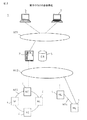
以下、添付する図面を参照して実施例を説明する。図3は、開示のオペレーションシステム(OpS)の全体構成を表示対象となるネットワークを含めて示す図である。OpS1は、伝送ネットワークNT3及びNT4を構成する伝送装置(NE)4を制御するNE−OpSサーバ2(以下、単に「サーバ」と記す)と、伝送装置4に関する情報を管理するデータベース(DB)5と、サーバ2へのインタフェースを保守要員に与えるOpSクライアントであるヒューマンマシンインタフェース(HMI)6と、サーバ2とヒューマンマシンインタフェース6とを接続するデータ通信ネットワークNT1と、サーバ2と伝送ネットワークNT3及びNT4内のゲートウエイネットワーク構成要素とを接続するデータ通信ネットワークNT2を備える。
ここで、伝送ネットワークNT3及びNT4はOpSの表示対象となるネットワークである。
Hereinafter, embodiments will be described with reference to the accompanying drawings. FIG. 3 is a diagram illustrating the entire configuration of the disclosed operation system (OpS) including the network to be displayed. The OpS 1 is a NE-OpS server 2 (hereinafter simply referred to as “server”) that controls transmission apparatuses (NE) 4 constituting the transmission networks NT 3 and NT 4, and a database (DB) 5 that manages information about the
Here, the transmission networks NT3 and NT4 are networks for which OpS is displayed.
データベース5は、伝送ネットワークNT3及びNT4を構成する伝送装置4に関する情報を管理するため、装置情報データと、所在地情報データと、住所情報データを記憶する。
サーバ2及び/又はヒューマンマシンインタフェース6は、伝送ネットワークNT3及びNT4を保守する保守要員に対し、サーバ2及び/又はヒューマンマシンインタフェース6に接続されたディスプレイ装置に、伝送ネットワークNT3及びNT4に関するネットワーク図を表示する。サーバ2及び/又はヒューマンマシンインタフェース6に接続されたディスプレイ装置上に表示するネットワーク図を、以下簡単に「ネットワーク図」と記す。サーバ2及び/又はヒューマンマシンインタフェース6は、ネットワーク図を表示する際に、データベース5内の装置情報データに含まれる各伝送装置4の座標値(X座標、Y座標)を読み出して、各伝送装置4の配置位置を決定する。このためサーバ2は、各伝送装置4をデータベース5に登録するとき、伝送装置4の表示位置を決定して装置情報データに登録する。
The
The
図4は、データベース5に記憶される装置情報データのデータ構造を示す図である。本実施例の装置情報データは、「装置ID」カラム、「装置名」カラム、「所在地ID」カラム、「隣接装置ID」カラム、「X座標」カラム及び「Y座標」カラムを有する。
「装置ID」カラムには各伝送装置の識別子が格納され、「装置名」カラムにはユーザが設定可能な各伝送装置の名称が格納され、「所在地ID」カラムには伝送装置が設置される所在地に対して後述の所在地情報データ(図5)内で使用される所在地IDの値が格納され、「隣接装置ID」カラムには、隣接する伝送装置を示す装置IDの値が格納され、「X座標」カラム及び「Y座標」カラムには、ネットワーク図における、該当する伝送装置の表示位置のX座標値及びY座標値が格納される。
なお本明細書において、上述の「隣接する伝送装置」の語は、伝送ネットワークNT3及びNT4において当該伝送装置にリンク(伝送路)により直接接続された伝送装置の意味で使用される。
FIG. 4 is a diagram showing a data structure of device information data stored in the
The “device ID” column stores the identifier of each transmission device, the “device name” column stores the name of each transmission device that can be set by the user, and the “location ID” column stores the transmission device. A location ID value used in location information data (FIG. 5), which will be described later, is stored for the location. In the “adjacent device ID” column, a device ID value indicating an adjacent transmission device is stored. In the “X coordinate” column and the “Y coordinate” column, the X coordinate value and the Y coordinate value of the display position of the corresponding transmission device in the network diagram are stored.
In the present specification, the term “adjacent transmission apparatus” is used to mean a transmission apparatus directly connected to the transmission apparatus via a link (transmission path) in the transmission networks NT3 and NT4.
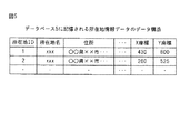
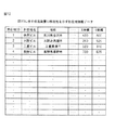
図5は、データベース5に記憶される所在地情報データのデータ構造を示す図である。本実施例の所在地情報データは、「所在地ID」カラム、「所在地名」カラム、「住所」カラム、「X座標」カラム及び「Y座標」カラムを有する。
「所在地ID」カラムには、各所在地の識別子が格納され、「所在地名」カラムにはユーザが設定可能な所在地の名称(例えばxxビルなど)が格納され、「住所」カラムには所在地が存在する住所が格納され、「X座標」カラム及び「Y座標」カラムには、所在地に対応するネットワーク図上の表示位置のX座標値及びY座標値が格納される。
FIG. 5 is a diagram showing the data structure of location information data stored in the
The “location ID” column stores an identifier of each location, the “location name” column stores a name of a location that can be set by the user (for example, xx building), and the “address” column has a location. The “X coordinate” column and the “Y coordinate” column store the X coordinate value and the Y coordinate value of the display position on the network diagram corresponding to the location.
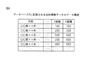
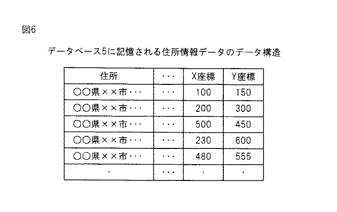
図6は、データベース5に記憶される住所情報データのデータ構造を示す図である。本実施例の住所情報データは、「住所」カラム、「X座標」カラム及び「Y座標」カラムを有する。「住所」カラムには各住所が格納され、「X座標」カラム及び「Y座標」カラムには住所に対応するネットワーク図上の表示位置のX座標値及びY座標値が格納される。
FIG. 6 is a diagram showing the data structure of the address information data stored in the
図7は、開示のサーバ2のハードウエア構成を示す図である。サーバ2は、CPU21と、メモリ22と、オペレーディングシステム(OS)28やプログラムを記憶するためのハードディスクドライブ23、キーボードやマウスなどの入力機器24、ディスプレイ装置などの出力機器25、プログラムやOSのインストール及びデータの入出力のためのドライブ装置26、データベース5やネットワークNT1及びNT2との接続のための通信ネットワーク27を備えて構成される。
ハードディスクドライブ23には、サーバ2により実行され、ネットワーク図上における各伝送装置の表示位置を決定する処理を、サーバ2に実行させるネットワーク図登録処理プログラム29がインストールされている。
FIG. 7 is a diagram illustrating a hardware configuration of the disclosed
The
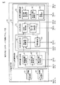
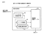
図8は、サーバ2の機能ブロック図である。サーバ2がネットワーク図登録処理プログラム29を実行することによって、ネットワーク登録処理部30に示す各機能が実行される。
ネットワーク登録処理部30は、図2の(A)及び図2の(B)を参照して説明した、リニア構成ネットワーク及びリング構成ネットワーク用のネットワーク図における各伝送装置4の配置を決定するリニア配置処理部31及びリング配置処理部32と、メッシュ配置ネットワーク用のネットワーク図における各伝送装置4の配置を決定するメッシュ配置処理部33とを備える。
FIG. 8 is a functional block diagram of the
The network
メッシュ配置処理部33は、中間位置決定部40と、所在地決定部50と、再配置部60と、住所決定部70と、位置情報調整部80とを備える。
中間位置決定部40は、ネットワーク図内の表示位置を決定すべき伝送装置4(以下、「対象装置」と記す)の隣接装置のそれぞれの表示位置の中間位置を、対象装置の表示位置として決定する。
The mesh
The intermediate
中間位置決定部40は、装置情報データに含まれる対象装置に関するレコードの中から、対象装置と隣接装置との接続関係を示す「隣接装置ID」カラムのデータを参照して各隣接装置を決定する隣接装置決定部41と、決定された隣接装置の装置IDに基づいて、装置情報データに含まれる各隣接装置に関するレコード中の「X座標」カラム及び「Y座標」カラムのデータをそれぞれ参照して各隣接装置の表示位置の座標値を取得する表示位置取得部42と、表示位置取得部42により取得された各隣接装置の表示位置の中間位置を算出し、対象装置の表示位置として決定する表示位置決定部43を備える。
The intermediate
所在地決定部50は、所在地情報データの中から、中間位置決定部40により決定された対象装置の表示位置に最も近い座標データが「X座標」カラム及び「Y座標」カラムに保持されている所在地を検索する所在地検索部51を備える。
The
住所決定部70は、中間位置決定部40により決定された対象装置の表示位置と、この対象装置について所在地決定部50により検索された所在地の座標との間の距離が所定の閾値よりも大きいとき、住所情報データの中から、中間位置決定部40により決定された対象装置の表示位置に最も近い座標データが「X座標」カラム及び「Y座標」カラムに保持されている住所を検索する住所検索部71と、住所検索部71により検索された住所情報を有する所在地に関するレコードを、所在地情報データに新たに登録する所在地データ登録部72と、を備える。
When the
再配置部60は、所在地検索51によって検索された所在地の「X座標」カラム及び「Y座標」カラムに保持された座標データ、又は所在地データ登録部72により登録された所在地の「X座標」カラム及び「Y座標」カラムに保持された座標データに、対象装置の表示位置を再配置する。
The
位置情報調整部80は、再配置部60による処理によって、複数の対象装置がネットワーク図上の同一の表示位置に配置されたとき、これらの対象装置が重なって表示されないように表示位置を調整する。位置情報調整部80は、再配置部60により同一の表示位置に再配置された複数の対象装置のそれぞれについて、各隣接装置であって対象装置の表示位置に配置されていないものの表示位置と対象装置の表示位置との間の変位量の合計値を決定する変位量合計値決定部81と、各対象装置について決定したそれぞれの合計値に応じて、元の表示位置及びその代替位置とからなる複数の表示候補位置のいずれかに、各伝送装置の表示位置を分配する表示位置調整部82と、表示位置調整部82により同一の表示候補位置に複数の装置が配置されたとき競合関係を解消する競合処理部83と、を備える。
When the plurality of target devices are arranged at the same display position on the network diagram by the processing by the
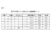
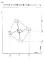
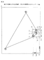
図9は、伝送装置の表示位置決定方法の第1例を示すフローチャートである。現在、図10に示すように、伝送装置A、B、C、DがOpS1のネットワーク図Dに既に登録されている。ネットワーク図Dにおいて、伝送装置A、B、C、D間を接続するリンクはL1〜L4によって表示されている。いまネットワーク図Dに、伝送装置A、B、C、Dを隣接装置とする新たな伝送装置Eを登録する場合を考える。
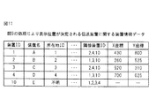
図11は、データベース5に記憶される伝送装置A〜Eに関する装置情報データを示す図であり、図12は、データベース5に記憶される伝送装置A〜Dの所在地を示す所在地情報データを示す図である。
図11に示すように、この時点では、伝送装置Eの所在地IDは「不明」であり、ネットワーク図上の表示位置を示す座標はX座標、Y座標ともに未定であることを示す「−」となっている。
なお、伝送装置Eの隣接装置の情報は、伝送装置Eと各隣接装置とが接続されると例えば伝送装置間の監視情報の通信によって得ることができ、図11の例では、伝送装置Eは、装置ID1、2、3、4の各伝送装置が隣接していることを認識可能であり、この情報が装置情報データに反映されている。
FIG. 9 is a flowchart illustrating a first example of the display position determination method of the transmission apparatus. At present, as shown in FIG. 10, transmission apparatuses A, B, C, and D are already registered in the network diagram D of OpS1. In the network diagram D, links connecting the transmission apparatuses A, B, C, and D are indicated by L1 to L4. Consider a case where a new transmission apparatus E having transmission apparatuses A, B, C, and D as adjacent apparatuses is registered in the network diagram D.
11 is a diagram showing device information data related to the transmission devices A to E stored in the
As shown in FIG. 11, at this time, the location ID of the transmission apparatus E is “unknown”, and the coordinates indicating the display position on the network diagram are “−” indicating that both the X coordinate and the Y coordinate are undetermined. It has become.
The information on the neighboring device of the transmission device E can be obtained by, for example, communication of monitoring information between the transmission devices when the transmission device E and each neighboring device are connected. In the example of FIG. ,
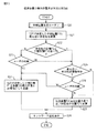
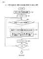
図9に示すステップS10において隣接装置決定部41は、装置情報データに記憶される対象装置Eに関するレコードの中から、対象装置と隣接装置との接続関係を示す「隣接装置ID」カラムのデータを参照して各隣接装置の装置IDを取得する。図11に示す装置情報データの例では、対象装置E(ID=10)の隣接装置A〜Dの装置ID=1、2、3及び4が取得される。
In step S10 shown in FIG. 9, the adjacent
ステップS11において表示位置取得部42は、装置情報データに記憶されている隣接装置A〜Dに関するそれぞれのレコードの中からX座標及びY座標を取得する。そして、ステップS12において表示位置決定部43は、これらの座標値の中間値をX座標及びY座標について算出して、これらの中間値を有する座標を、隣接装置A〜Dの表示位置の中間位置として決定する。
例えば表示位置決定部43は、隣接装置A〜Dに関するX座標の最大値と最小値との平均値をX座標の中間値として、隣接装置A〜Dに関するY座標の最大値と最小値との平均値をY座標の中間値として決定する。
図11の例の場合、隣接装置のX座標に関する最大値は装置Dの700であり、最小値は装置Bの260であるから、X座標の中間値として(700+260)/2=480を算出し、決定する。
また、隣接装置のY座標に関する最大値は装置Aの800であり最小値は装置Cの310であるから、Y座標の中間値を(800+310)/2=555を算出し、決定する。
そしてこれらX座標の中間値480及びY座標の中間値555をそれぞれX座標及びY座標として有する位置を、隣接装置A〜Dの表示位置の中間位置として決定する。
なお表示位置取得部42は、隣接装置A〜Dの表示位置の重心を中間位置として決定してもよい。
一例としては、隣接装置の数をNとしたとき、隣接装置の座標それぞれを合計してNで除算してその商を四捨五入して対象装置のX座標とし、隣接装置のY座標それぞれを合計してNで除算してその商を四捨五入して対象装置のY座標とする方法がある。
In step S <b> 11, the display position acquisition unit 42 acquires the X coordinate and the Y coordinate from the respective records regarding the adjacent devices A to D stored in the device information data. In step S12, the display
For example, the display
In the case of the example in FIG. 11, since the maximum value regarding the X coordinate of the adjacent device is 700 of the device D and the minimum value is 260 of the device B, (700 + 260) / 2 = 480 is calculated as the intermediate value of the X coordinate. ,decide.
Further, since the maximum value regarding the Y coordinate of the adjacent device is 800 of the device A and the minimum value is 310 of the device C, the intermediate value of the Y coordinate is calculated by determining (800 + 310) / 2 = 555.
A position having the
The display position acquisition unit 42 may determine the center of gravity of the display positions of the adjacent devices A to D as the intermediate position.
As an example, when the number of neighboring devices is N, the coordinates of the neighboring devices are totaled, divided by N, and the quotient is rounded to the X coordinate of the target device, and the Y coordinates of the neighboring devices are summed. There is a method of dividing by the N and rounding off the quotient to obtain the Y coordinate of the target device.
ステップS13において表示位置決定部43は、ステップS12で決定した中間位置(X480、Y=555)を、伝送装置Eの表示位置として装置情報データに登録する。
そして、ステップS14で、メッシュ配置処理部33は、装置情報データをヒューマンマシンインタフェース6に送信することにより、ネットワーク図を表示させる。
図13は、図9の処理により対象装置Eの表示位置が決定されるネットワーク図であり、図14は、図9の処理により対象装置Eに関するデータが変更された装置情報データを示す図である。
図13に示すように、伝送装置Eは、X座標480、Y座標555を中心とした位置にその装置を示す図形が表示されている。
また、図14に示すように、装置情報データの対象装置E、すなわち装置ID=10のX座標として480、Y座標として555が登録されている。
このように、本実施例によれば、メッシュ構成のネットワーク図表示において、たとえば、その所在地が未定である伝送装置が追加された場合でも、対象装置の隣接装置の表示位置情報に基づいて自動的に対象装置の表示位置を決定することができる。
In step S13, the display
In step S14, the mesh
FIG. 13 is a network diagram in which the display position of the target device E is determined by the processing of FIG. 9, and FIG. 14 is a diagram showing device information data in which data related to the target device E is changed by the processing of FIG. .
As shown in FIG. 13, in the transmission apparatus E, a graphic indicating the apparatus is displayed at a position centered on the X coordinate 480 and the Y coordinate 555.
As shown in FIG. 14, 480 is registered as the X coordinate of the target device E of the device information data, that is, device ID = 10, and 555 is registered as the Y coordinate.
As described above, according to the present embodiment, even when a transmission device whose location is undetermined is added in the network diagram display of the mesh configuration, for example, automatically based on the display position information of the adjacent device of the target device. The display position of the target device can be determined.
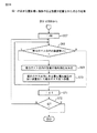
図15は、伝送装置の表示位置決定方法の第2例を示すフローチャートである。本例では、中間位置決定部40が対象装置Eの表示位置として決定した座標に近い座標(所在地)が、データベース5の所在地情報データベースに登録されているか否かを検索し、登録されている場合にはその座標(所在地)に対応するネットワーク図上の位置を、対象装置Eの表示位置として登録する。
FIG. 15 is a flowchart illustrating a second example of the display position determination method of the transmission apparatus. In this example, when the coordinate (location) close to the coordinate determined by the intermediate
ステップS20では、図9に示すS10〜S12と同様にして中間位置決定部40が隣接装置の表示位置の座標値の中間位置P1(X=480、Y=555)を決定する。
ステップS21において所在地検索部51は、データベース5内に記憶された所在地情報データから、「X座標」カラム及び「Y座標」カラムに記憶された位置が中間位置P1に最も近い所在地を検索する。
In step S20, the intermediate
In step S <b> 21, the
例えば、所在地検索部51は、中間位置P1のX座標値及びY座標値をそれぞれX1及びY1とし、所在地のX座標及びY座標値をX2及びY2とするとき、中間位置P1と所在地との間の距離をZ=|X1−X2|+|Y1−Y2|により計算し、かかる距離が最も短い所在地を検索する。
図16は、図13に示す伝送装置Eに近い所在地データを含む所在地情報データを示す図である。図16に示す例では、所在地ID=100として登録されているX座標=520及びY座標=625を有する「岐阜ビル」が中間位置P1に最も近い所在地として検索されたこととする。また検索された所在地の位置(X座標=520,Y座標=625)を位置P2と示す。
For example, the
FIG. 16 is a diagram showing location information data including location data close to the transmission device E shown in FIG. In the example shown in FIG. 16, it is assumed that “Gifu Building” having X coordinate = 520 and Y coordinate = 625 registered as the location ID = 100 is searched as the location closest to the intermediate position P1. The position of the searched location (X coordinate = 520, Y coordinate = 625) is indicated as position P2.
ステップS22においてメッシュ配置処理部33は、検索された所在地の位置P2と中間位置P1との間の距離が所定の閾値Thよりも小さいか否かを判定する。位置P2とP1の間の距離が閾値Thよりも小さくない場合、メッシュ配置処理部33は、ステップS23にて、ヒューマンマシンインタフェース6にその旨を表示してユーザの指示を受け付ける。検索された所在地の位置P2を対象装置Eの表示位置として使用することをユーザが許可しない場合には、ステップS24において、図9に示すステップS13と同様に中間位置P1を対象装置Eの表示位置として登録する。
In step S22, the mesh
ステップS22の判定において位置P2と中間位置P1との間の距離が所定の閾値Thよりも小さい場合、又はステップS23の判定においてユーザが位置P2を対象装置Eの表示位置として使用することを許可した場合には、ステップS25においてメッシュ配置処理部33は、所在地検索部51により検索された所在地が複数あるか否かを判定する。
所在地検索部51により検索された所在地が複数ある場合には、ステップS26においてヒューマンマシンインタフェース6にその旨を表示してユーザの指示を受け付ける。検索された所在地の位置P2を対象装置Eの表示位置として使用することをユーザが許可しない場合には、ステップS24において中間位置P1を対象装置Eの表示位置として登録する。
When the distance between the position P2 and the intermediate position P1 is smaller than the predetermined threshold Th in the determination in step S22, or the determination in step S23 allows the user to use the position P2 as the display position of the target device E. In this case, in step S25, the mesh
If there are a plurality of locations searched by the
ステップS25の判定において所在地検索部51により検索された所在地が単数である場合には、ステップS27において再配置部60は、対象装置Eの表示位置を、検索された所在地の位置P2(X座標=520、Y座標=625)へ再配置する。また、装置情報データ中の対象装置Eに関するレコードの「所在地ID」カラムの値を、検索された所在地の所在地IDの値(100)へ変更する。図17は、図15の処理により変更された装置情報データを示す図である。
またステップS26の判定において所在地の位置P2を対象装置Eの表示位置として使用することをユーザが許可した場合には、ステップS27において、再配置部60は、検索された複数の所在地のいずれかの位置P2を対象装置Eの表示位置として登録する。
ステップS28においてメッシュ配置処理部33は、装置情報データをヒューマンマシンインタフェース6に送信することにより、ネットワーク図を表示させる。図18は、図15の処理により伝送装置Eの表示位置が再配置されるネットワーク図である。
本実施例によれば、対象装置の隣接装置の表示位置から算出した対象装置の表示位置(座標)から、近傍の登録された所在地(座標)を検索する。そして、ネットワーク運用管理者は、所在地が未定である対象装置の表示位置の決定において、隣接装置の表示位置から決定された中間位置と、登録された所在地に対応する位置と、から対象装置の表示位置(座標)を選択可能となる効果がある。
If the location searched by the
If the user permits the location P2 of the location to be used as the display location of the target device E in step S26, the
In step S <b> 28, the mesh
According to the present embodiment, the registered location (coordinates) in the vicinity is searched from the display position (coordinates) of the target device calculated from the display position of the adjacent device of the target device. The network operation manager determines the display position of the target device from the intermediate position determined from the display position of the adjacent device and the position corresponding to the registered location in determining the display position of the target device whose location is undetermined. There is an effect that the position (coordinates) can be selected.
図19は、伝送装置の表示位置決定方法の第3例を示すフローチャートである。本例では、中間位置決定部40が対象装置Eの表示位置として決定した座標に近い住所が、データベース5の住所データベースに登録されているか否かを検索し、登録されている場合にはその住所に対応するネットワーク図上の位置を、対象装置Eの表示位置として登録する。
FIG. 19 is a flowchart illustrating a third example of the display position determination method of the transmission apparatus. In this example, it is searched whether or not an address close to the coordinates determined by the intermediate
ステップS30では、図9に示すS10〜S12と同様にして中間位置決定部40が隣接装置の表示位置の座標値の中間位置P1(X=480、Y=555)を決定する。
ステップS31において所在地検索部51は、データベース5内に記憶された所在地情報データから、「X座標」カラム及び「Y座標」カラムに記憶された位置が中間位置P1に最も近い所在地を検索する。ここでは図16に示す所在地情報データの所在地ID=100のレコードに記録される「岐阜ビル」が検索されたものと仮定する。
In step S30, the intermediate
In step S31, the
ステップS32においてメッシュ配置処理部33は、検索された所在地の位置P2と中間位置P1との間の距離が所定の閾値Thよりも小さいか否かを判定する。位置P2とP1の間の距離が閾値Thよりも小さい場合、ステップS34においてメッシュ配置処理部33は、所在地検索部51により検索された所在地が複数あるか否かを判定する。所在地検索部51により検索された所在地が複数ある場合には、ステップS35においてヒューマンマシンインタフェース6にその旨を表示してユーザの指示を受け付ける。
In step S32, the mesh
ステップS34の判定において所在地検索部51により検索された所在地が単数である場合、又はステップS35の判定において検索された所在地の位置P2を対象装置Eの表示位置として使用することをユーザが許可した場合には、図15に示すステップS27と同様にして、再配置部60は、検索された所在地の位置P2を対象装置Eの表示位置として登録する。
When the location searched by the
ステップS32の判定において、所在地の位置P2と中間位置P1との間の距離が所定の閾値Thよりも小さくないとき、メッシュ配置処理部33は、ステップS37にて、ヒューマンマシンインタフェース6にその旨を表示してユーザの指示を受け付ける。位置P2を対象装置Eの表示位置として使用することをユーザが許可する場合には処理を上記ステップS34に移す。
If it is determined in step S32 that the distance between the location position P2 and the intermediate position P1 is not smaller than the predetermined threshold Th, the mesh
ステップS37又はステップS35の判定において、検索された所在地の位置P2を対象装置Eの表示位置として使用することをユーザが許可しない場合には、ステップS38において、図8に示す住所検索部71は、データベース5内に記憶された住所情報データから、「X座標」カラム及び「Y座標」カラムに記憶された位置が中間位置P1に最も近い住所を検索する。
In the determination in step S37 or step S35, when the user does not permit the use of the searched location P2 as the display position of the target device E, in step S38, the
例えば、住所検索部71は、中間位置P1のX座標値及びY座標値をそれぞれX1及びY1とし、住所のX座標及びY座標値をX3及びY3とするとき、中間位置P1と所在地との間の距離をZ=|X1−X3|+|Y1−Y3|により計算し、かかる距離が最も短い住所を検索してよい。
図20は、図13に示す伝送装置Eに近い住所データを含む住所情報データを示す図である。図20に示す例では、X座標=480及びY座標=555を有する「愛知県名古屋市」が中間位置P1に最も近い住所として検索されたこととする。また検索された住所の位置(X座標=480,Y座標=555)を位置P3と示す。
For example, when the
FIG. 20 is a diagram illustrating address information data including address data close to the transmission apparatus E illustrated in FIG. In the example illustrated in FIG. 20, it is assumed that “Nagoya, Aichi Prefecture” having an X coordinate = 480 and a Y coordinate = 555 is searched as an address closest to the intermediate position P1. The position of the searched address (X coordinate = 480, Y coordinate = 555) is indicated as position P3.
ステップS39において所在地データ登録部72は、住所検索部71が検索した住所「愛知県名古屋市」のレコードの「住所」カラム、「X座標」カラム及び「Y座標」カラムに記憶されているデータと同じ情報を有する新規のレコードを、所在地情報データに登録する。その際に所在地データ登録部72は、新規レコードの「所在地名」カラムに記憶する所在地の名称をユーザに問い合わせてもよい。
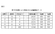
図21は、図19の処理により変更された所在地情報データを示す図である。図20に示す住所情報データの「愛知県名古屋市」のレコードの「住所」カラム、「X座標」カラム及び「Y座標」カラムに記憶されているデータと同じ情報を有する、ID=250のレコードが新たに登録されている。
In step S39, the location
FIG. 21 is a diagram showing the location information data changed by the processing of FIG. Record of ID = 250 having the same information as the data stored in the “address” column, “X coordinate” column, and “Y coordinate” column of the record of “Nagoya City, Aichi Prefecture” of the address information data shown in FIG. Is newly registered.
ステップS40において、再配置部60は、対象装置Eの表示位置を、追加された所在地の位置P3(ID=250、X座標=480、Y座標=555)へ再配置する。また、装置情報データ中の対象装置Eに関するレコードの「所在地ID」カラムの値を、検索された所在地の所在地IDの値(250)へ変更する。図22は、図19の処理により変更された装置情報データを示す図である。
ステップS41においてメッシュ配置処理部33は、装置情報データをヒューマンマシンインタフェース6に送信することにより、ネットワーク図を表示させる。図23は、図19の処理により伝送装置Eの表示位置が再配置されるネットワーク図である。
本実施例によれば、予め画面上の座標が登録された住所の座標の中から、対象装置の隣接装置の表示位置から算出した対象装置の表示位置(座標)の近傍にある住所の座標を検索する。そしてネットワーク管理者は、所在地が未定である対象装置の表示位置の決定において、隣接装置の表示位置から決定された中間位置と、登録された住所の座標とから、対象装置の表示位置を選択可能となる効果がある。
In step S40, the
In step S41, the mesh
According to the present embodiment, the coordinates of the address in the vicinity of the display position (coordinate) of the target device calculated from the display position of the adjacent device of the target device are selected from the coordinates of the address whose coordinates on the screen are registered in advance. Search for. Then, the network administrator can select the display position of the target device from the intermediate position determined from the display position of the neighboring device and the coordinates of the registered address when determining the display position of the target device whose location is undetermined There is an effect.
以下に示す実施例では、同一位置に配置された複数の伝送装置のアイコンが重複して表示されないように表示位置を調整する方法を示す。
同じ所在地、例えば局舎に複数の伝送装置が存在するなどの理由によって、図15又は図19に示す処理の結果、ネットワーク図上の同一位置に複数の伝送装置が配置されることが生じる。図24は、同一位置に配置された複数、ここでは3台の伝送装置F、G及びHに関する情報を含む装置情報データを示す図であり、図25は、図24に示す伝送装置F〜Jの所在地を示す所在地情報データを示す図である。本例では伝送装置F、G及びHが同一の所在地(所在地ID=1の「福岡ビル」)にある結果、どの装置についても表示位置がX座標=440、Y座標100になっている。
同一位置に複数の伝送装置が配置されると、ネットワーク図にはこれらの伝送装置のアイコンが重なって表示され、これら伝送装置の識別が困難となる。また、同一表示位置の伝送装置間の接続関係(リンク)も識別が困難となる。
In the embodiment described below, a method of adjusting the display position so that icons of a plurality of transmission apparatuses arranged at the same position are not displayed redundantly is shown.
As a result of the processing shown in FIG. 15 or FIG. 19, a plurality of transmission devices may be arranged at the same position on the network diagram because there are a plurality of transmission devices in the same location, for example, in a station. FIG. 24 is a diagram showing device information data including information on a plurality of, here three, transmission devices F, G, and H arranged at the same position, and FIG. 25 shows the transmission devices F to J shown in FIG. It is a figure which shows the location information data which shows the location. In this example, as a result of the transmission devices F, G, and H being at the same location (“Fukuoka Building” with location ID = 1), the display position is X coordinate = 440 and Y coordinate 100 for any device.
When a plurality of transmission apparatuses are arranged at the same position, icons of these transmission apparatuses are displayed in an overlapping manner on the network diagram, and it becomes difficult to identify these transmission apparatuses. In addition, it is difficult to identify the connection relationship (link) between transmission devices at the same display position.
まず、複数の伝送装置が配置された同一の表示位置(以下「元の表示位置」と示す)を中心とする代替表示位置を定め、元の表示位置と代替表示位置とからなる配置位置候補を決定する。図26の(A)は、配置位置候補の例を示す図であり、計9個の配置位置候補S1〜S9は、元の表示位置S1とその代替位置S2〜S9からなる。 First, an alternative display position centering on the same display position (hereinafter referred to as “original display position”) where a plurality of transmission devices are arranged is determined, and an arrangement position candidate consisting of the original display position and the alternative display position is determined. decide. FIG. 26A shows an example of arrangement position candidates. A total of nine arrangement position candidates S1 to S9 are composed of the original display position S1 and its alternative positions S2 to S9.
図26の(A)に示すように、代替表示位置のマス目S3、S2及びS9は、元の表示位置のマス目S1から−60ピクセルだけX座標方向に移動させたマス目であり、マス目S5〜S7は、マス目S1から+60ピクセルだけX座標方向に移動させたマス目である。
そして、マス目S3〜S5は、マス目S1から+75ピクセルだけY座標方向に移動させたマス目であり、マス目S7〜S9は、マス目S1から−75ピクセルだけY座標方向に移動させたマス目である。
ここで、伝送装置を示すアイコンとして、幅、高さのそれぞれが60ピクセルより小さいものを使用すれば、各代替位置にそれぞれアイコンを表示させてもその表示は重ならないことになる。
図24に示す装置情報データにおいて複数の伝送装置F〜Hが配置された位置について生成する配置位置候補S1〜S9の座標を図26の(B)に示す。なお、本例では3×3=9個の配置位置候補を使用したがこれは例示であって、配置位置候補の数及び配置方法は必要に応じて他の適切な数及び配置方法を使用できることは明らかである。
As shown in FIG. 26A, the cells S3, S2 and S9 at the alternative display positions are cells moved in the X coordinate direction by −60 pixels from the cells S1 at the original display position. The eyes S5 to S7 are squares moved in the X coordinate direction by +60 pixels from the square S1.
The squares S3 to S5 are squares moved in the Y coordinate direction by +75 pixels from the square S1, and the squares S7 to S9 are moved in the Y coordinate direction by −75 pixels from the square S1. It is a grid.
Here, if an icon indicating a transmission device having a width and a height smaller than 60 pixels is used, even if the icon is displayed at each alternative position, the display does not overlap.
FIG. 26B shows the coordinates of the arrangement position candidates S1 to S9 generated for the position where the plurality of transmission apparatuses F to H are arranged in the apparatus information data shown in FIG. In this example, 3 × 3 = 9 placement position candidates are used, but this is an example, and the number of placement position candidates and the placement method can use other appropriate numbers and placement methods as necessary. Is clear.
次に、同一位置に配置された複数の伝送装置F、G及びHを、各配置位置候補S1〜S9のいずれかに配置する。伝送装置F、G及びHを配置する際には、これら伝送装置F、G及びHのうち、他の伝送装置I及びJと直接接続されない(すなわち伝送装置I及びJの隣接装置でない)装置を、各配置位置候補S1〜S9の中心の位置S1に配置する。
これは、伝送装置間に表示するリンクの交差が少なくなるためである。
この動作は、具体的には図24に示す装置情報データにおいて、同一位置に配置されている各伝送装置のエントリの隣接装置IDをそれぞれ検索する。すなわち、他の伝送装置、ここでは装置ID3、4、5以外の装置IDが隣接装置IDに含まれるか否かにより、他の伝送装置とのリンクがあるかないかを判定する。
Next, a plurality of transmission devices F, G, and H arranged at the same position are arranged in any one of the arrangement position candidates S1 to S9. When the transmission apparatuses F, G, and H are arranged, an apparatus that is not directly connected to the other transmission apparatuses I and J (that is, not an adjacent apparatus of the transmission apparatuses I and J) among the transmission apparatuses F, G, and H is selected. These are arranged at the center position S1 of the respective arrangement position candidates S1 to S9.
This is because the number of link intersections displayed between transmission apparatuses is reduced.
Specifically, this operation searches the adjacent device IDs of the entries of the respective transmission devices arranged at the same position in the device information data shown in FIG. That is, it is determined whether or not there is a link with another transmission device, depending on whether or not another transmission device, here, a device ID other than
また、伝送装置F、G及びHのうちこれらの元の表示位置S1よりもX座標が大きい隣接装置と接続されている装置を、元の表示位置S1よりもX座標が大きいマス目S5〜S7に配置する。伝送装置F〜Hのうち元の表示位置S1よりもX座標が小さい隣接装置と接続されている装置を、元の表示位置S1よりもX座標が小さいマス目S3、S2及びS9に配置する。伝送装置F〜Hのうち元の表示位置S1よりもY座標が大きい隣接装置と接続されている装置を、元の表示位置S1よりもY座標が大きいマス目S3〜S5に配置する。伝送装置F〜Hのうち元の表示位置S1よりもY座標が小さい隣接装置と接続されている装置を、元の表示位置S1よりもY座標が小さいマス目S7〜S9に配置する。これはリンクの交差を少なくするためである。
この処理は、具体的には図24に示す装置情報データにおいて、各伝送装置F、G及びHのエントリについて、隣接装置IDをそれぞれ検索し、検索された隣接装置IDが示す各伝送装置のうち、これら伝送装置F、G及びHの表示位置S1と異なる位置に配置された隣接装置を選択する。そして、選択された各隣接装置の表示位置のそれぞれのX座標と表示位置S1のX座標との間の差の合計値を算出する。また選択された各隣接装置の表示位置のそれぞれのY座標と表示位置S1のY座標との間の差の合計値を算出する。そしてこれら合計値に従って各伝送装置をマス目S2〜S9のいずれに配置するかを決定する。
Further, among the transmission devices F, G, and H, the devices connected to the neighboring devices having the X coordinate larger than the original display position S1 are assigned to the cells S5 to S7 having the X coordinate larger than the original display position S1. To place. Among the transmission devices F to H, devices connected to neighboring devices having an X coordinate smaller than that of the original display position S1 are arranged in the cells S3, S2, and S9 having an X coordinate smaller than that of the original display position S1. Among the transmission devices F to H, devices connected to neighboring devices having a larger Y coordinate than the original display position S1 are arranged in the cells S3 to S5 having a larger Y coordinate than the original display position S1. Among the transmission devices F to H, devices connected to adjacent devices having a Y coordinate smaller than the original display position S1 are arranged in the cells S7 to S9 having a Y coordinate smaller than the original display position S1. This is to reduce the number of link crossings.
Specifically, this process searches the neighboring device ID for each entry of the transmission devices F, G, and H in the device information data shown in FIG. 24, and among the transmission devices indicated by the searched neighboring device ID. Then, an adjacent device arranged at a position different from the display position S1 of these transmission devices F, G and H is selected. And the total value of the difference between each X coordinate of the display position of each selected adjacent apparatus and X coordinate of the display position S1 is calculated. Further, the total value of the differences between the respective Y coordinates of the display positions of the selected adjacent devices and the Y coordinates of the display position S1 is calculated. Then, according to these total values, it is determined in which of the cells S2 to S9 each transmission device is arranged.
このため、同一位置S1に再配置された複数の伝送装置F、G及びHのそれぞれについて、伝送装置に接続する伝送装置である各隣接装置であって、かつ同一位置S1に配置されていないものを特定する。例えば、伝送装置Hについては、その隣接装置F、G及びJのうち位置S1に配置されていない装置は装置Jであり、伝送装置Gについては、その隣接装置F、H及びIのうち位置S1に配置されていない装置は装置Iであり、伝送装置Fについては、その隣接装置のうち位置S1に配置されていない装置はない。
そして、複数の伝送装置F、G及びHのそれぞれと、これら装置についてそれぞれ特定した隣接装置との間の座標値の差をX座標方向及びY座標方向について決定し、ぞれぞれの差の合計値を指標値として決定する。複数の伝送装置F、G及びHのうちの各装置iについてそれぞれ特定された隣接装置をjで表すとすると、各装置iについての指標値は次式(1)で表される。
Therefore, each of the plurality of transmission devices F, G, and H rearranged at the same position S1 is each adjacent device that is a transmission device connected to the transmission device and is not arranged at the same position S1. Is identified. For example, for the transmission device H, the device that is not arranged at the position S1 among the neighboring devices F, G, and J is the device J, and for the transmission device G, the position S1 among the neighboring devices F, H, and I. The device that is not disposed at is the device I, and there is no device that is not disposed at the position S1 among the adjacent devices for the transmission device F.
Then, the difference in coordinate values between each of the plurality of transmission devices F, G, and H and the adjacent devices specified for these devices is determined for the X coordinate direction and the Y coordinate direction, and the difference of each difference is determined. The total value is determined as the index value. If an adjacent device specified for each device i among the plurality of transmission devices F, G, and H is represented by j, the index value for each device i is represented by the following equation (1).
例えば、装置GについてのX座標の指標値は900(装置IのX座標)−440=460となり、Y座標の指標値は365(装置IのY座標)−100=265となり、装置HについてのX座標の指標値は100(装置JのX座標)−440=−340となり、Y座標の指標値は900(装置JのY座標)−100=800となり、装置FについてのX座標及びY座標の指標値は0となる。 For example, the index value of the X coordinate for the device G is 900 (X coordinate of the device I) −440 = 460, and the index value of the Y coordinate is 365 (Y coordinate of the device I) −100 = 265. The index value of the X coordinate is 100 (X coordinate of the apparatus J) −440 = −340, the index value of the Y coordinate is 900 (Y coordinate of the apparatus J) −100 = 800, and the X coordinate and the Y coordinate of the apparatus F are The index value of is 0.
一方で、各マス目S1〜S9に配置すべき装置の指標値の範囲を定める。図26の(C)は、各マス目S1〜S9に配置すべき装置の指標値の範囲を示す図である。そして各装置F、G及びHを、その指標値を含む範囲を有するマス目に配置する。
上記例では、装置Fはマス目S1に、装置Gはマス目S6に、装置Hはマス目S3に配置される。
On the other hand, the range of the index value of the device to be arranged in each of the cells S1 to S9 is determined. (C) of FIG. 26 is a figure which shows the range of the index value of the apparatus which should be arrange | positioned to each square S1-S9. And each apparatus F, G, and H is arrange | positioned at the square which has the range containing the index value.
In the above example, the device F is arranged in the cell S1, the device G is arranged in the cell S6, and the device H is arranged in the cell S3.
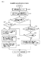
図27は、伝送装置の表示位置決定方法の第4例を示すフローチャートである。ステップS50において図8に示す中間位置決定部40、所在地決定部50、再配置部60及び住所決定部70により、図9、図15及び図19を参照して説明した処理と同様にして、各伝送装置の配置位置を決定する。
ステップS51において位置情報調整部80は、同一位置に配置された複数の伝送装置が存在するか否かを判定する。このような伝送装置がなければ処理を終了する。
ステップS52において表示位置調整部82は、ステップS51において検出した複数の伝送装置が配置された位置に対して、図26の(A)及び図26の(B)を参照して説明した配置位置候補S1〜S9を決定する。
FIG. 27 is a flowchart illustrating a fourth example of the display position determination method of the transmission apparatus. In step S50, the intermediate
In step S51, the position
In step S52, the display
ステップS53〜S56に示すループは、ステップS51において検出した同一位置に配置された複数の伝送装置のそれぞれについて反復され、同一位置に配置された、最後の伝送装置の処理が終わるとループから抜け、ステップ57に移行する。ループ中で繰り返される1回の処理で対象とする装置を装置iと示す。
すると、同一位置に配置された伝送装置数をMとすると、このループに含まれる処理はi=1からMまでのM回の処理が行われる。
ステップS54及びS55では変位量合計値決定部81が各装置iについて上記式(1)に示す指標値を決定する。
ステップS57において表示位置調整部82は、そしてステップS51において検出した同一位置に配置された各装置を、その指標値を含む範囲を有する配置位置候補に配置するように、装置情報データベースを変更する。
The loop shown in steps S53 to S56 is repeated for each of the plurality of transmission devices arranged at the same position detected in step S51, and exits from the loop when the processing of the last transmission device arranged at the same position is completed. Control goes to step 57. A device to be processed in one process repeated in the loop is indicated as device i.
Then, assuming that the number of transmission apparatuses arranged at the same position is M, the processing included in this loop is performed M times from i = 1 to M.
In steps S54 and S55, the displacement total
In step S57, the display
図28は、図27の処理により伝送装置F、G及びHが配置されたネットワーク図である。図29は、図27の処理により変更された装置情報データを示す図である。
本実施例によれば、図15又は図19に示す処理の結果、たとえば同一所在地に配置されている等の理由によって複数の伝送装置が同一の表示位置に配置されても、これらの伝送装置の表示位置の重なりを解消して、伝送装置の識別を容易にするという効果がある。
FIG. 28 is a network diagram in which transmission apparatuses F, G, and H are arranged by the process of FIG. FIG. 29 is a diagram showing the device information data changed by the processing of FIG.
According to the present embodiment, as a result of the processing shown in FIG. 15 or FIG. 19, even if a plurality of transmission apparatuses are arranged at the same display position due to reasons such as being arranged at the same location, There is an effect that the overlapping of the display positions is eliminated and the transmission apparatus can be easily identified.
図30は、図5に示す競合処理部83の構成例を示す図である。競合処理部83は、表示位置調整部82に示す処理によって、同一の配置位置候補に複数の装置が配置されたときに、これら複数の装置の間に優先順位を定めて優先順位の低い装置を他の配置位置候補に配置することにより、これら複数の装置間の競合を解消する。
競合処理部83は、仮配置記憶テーブル84と、インデックス変数操作部85と、ソート処理部86と、配置位置変更部87とを備える。
30 is a diagram illustrating a configuration example of the
The
仮配置記憶テーブル84は、表示位置調整部82が伝送装置を各配置位置候補に配置したとき、競合処理部83が複数の装置間の競合の解消処理を行う間、各配置位置候補への伝送状態の配置状態を記憶するテーブルである。図26の(A)を参照して説明した配置位置候補S1〜S9について構成される仮配置記憶テーブル84の例を以下に説明する。
2次元テーブルを有する仮配置記憶テーブル84の一つの次元である行番号で配置位置候補S1〜S9を表し、他方の次元である列番号によって各候補に配置された複数の装置を表すために、2次元配置されている配置位置候補S1〜S9間の順序を決定する。図31は、図26の(A)に示す各マス目の順序の決定例を説明する図であり、配置位置候補S1〜S9についてそれぞれ順序1〜9が割り当てられている。
The temporary arrangement storage table 84 is transmitted to each arrangement position candidate while the
In order to represent arrangement position candidates S1 to S9 by row numbers that are one dimension of the temporary arrangement storage table 84 having a two-dimensional table, and to represent a plurality of devices arranged in each candidate by column numbers that are the other dimension, The order between the two-dimensionally arranged placement position candidates S1 to S9 is determined. FIG. 31 is a diagram for explaining an example of determining the order of the squares shown in FIG. 26A.
図32は、図30に示す仮配置記憶テーブル84のデータ構造を示す図である。仮配置記憶テーブル84は、配置位置候補であるマス目S1〜S9のそれぞれについて1つのレコード(行)を有し、各行には、そのマス目に配置されている装置の数を記憶する「登録装置数」カラムと、各マス目に配置されている装置の装置IDをマス目数と同じ台数分(9台)記憶する1次元配列を有するデータ構造を有する。 FIG. 32 shows the data structure of the temporary arrangement storage table 84 shown in FIG. The temporary arrangement storage table 84 has one record (row) for each of the cells S1 to S9 which are arrangement position candidates, and each row stores the number of devices arranged in the cell. It has a data structure having a one-dimensional array for storing the “device number” column and the device IDs of the devices arranged in each cell for the same number (9) as the cell number.
図33及び図34は、同一の表示位置候補に複数の伝送装置が重なって配置された場合の処理を示すフローチャートである。
ステップS60において、表示位置調整部82が伝送装置を各マス目S1〜S9に配置したとき、各マス目S1〜S9における伝送装置の配置状態が仮配置記憶テーブル84に記憶される。表示位置調整部82により9台の伝送装置(装置ID=101〜109)が、マス目に配置された初期状態の例を図35の(A)に示す。本例では、装置ID=101〜103を有する3台の装置がマス目番号1のマス目S1に配置され、装置ID=104〜109を有する各装置がそれぞれマス目番号2〜7を有するマス目S2〜S7に配置された状態を示している。
FIG. 33 and FIG. 34 are flowcharts showing processing when a plurality of transmission apparatuses are arranged overlapping the same display position candidate.
In step S <b> 60, when the display
ステップS61においてインデックス変数操作部85が、インデックス変数iの値を「1」に初期化する。
ステップS62において、ソート処理部86は、仮配置記憶テーブル84内のi番目のマス目の行の「登録装置数」カラムに記憶される値を参照し、i番目のマス目に配置された装置数が2以上であるか否かを判定する。i番目のマス目に配置された装置数が1である場合には処理をステップS65に移す。
In step S61, the index
In step S62, the
ステップS62の判定において、i番目のマス目に配置された装置数が2以上である場合には、ソート処理部86は、ステップS63において仮配置記憶テーブル84のi行目に設けられた1次元配列に記憶された装置IDを、i番目のマス目について定められた所定の優先順位の基準に従ってソートし、優先順位のより高い装置IDをインデックスがより小さい列に移動し、優先順位のより低い装置IDをインデックスがより大きい列に移動する。
If it is determined in step S62 that the number of devices arranged in the i-th cell is 2 or more, the
図36に、各マス目S1〜S9に配置される装置の優先順位の基準の例を示す。
例えば1番目のマス目S1においては、配置された各装置の|X座標値|+|Y座標値|の値がより小さい装置ほど優先順位が高くなる。
また、3、5、7及び9番目のマス目S3、S5、S7及びS9においては、配置された各装置の|X座標値|+|Y座標値|の値がより大きい装置ほど優先順位が高くなる。
2及び6番目のマス目S2及びS6においては、配置された各装置の|X座標値|の値がより大きい装置ほど優先順位が高くなる。
4及び8番目のマス目S4及びS8においては、配置された各装置の|Y座標値|の値がより大きい装置ほど優先順位が高くなる。
FIG. 36 shows an example of priority criteria for devices arranged in the cells S1 to S9.
For example, in the first cell S1, the priority is higher for a device having a smaller | X coordinate value | + | Y coordinate value |
In the third, fifth, seventh, and ninth cells S3, S5, S7, and S9, a device having a larger | X coordinate value | + | Y coordinate value | Get higher.
In the second and sixth squares S2 and S6, the higher the | X coordinate value | of each arranged device, the higher the priority.
In the fourth and eighth squares S4 and S8, a device having a larger | Y coordinate value | of each device disposed has a higher priority.
図35の(A)に示す例では、i=1の場合のマスS1において装置ID=101、102及び103の順で優先順位が高く、ソートの結果、装置IDの移動が生じなかったものとする。
ステップS64では、配置位置変更部87がi番目のマス目に配置された装置のうち最も優先順位が低い装置をi+1番目のマス目に移動する。図35の(A)に示すマス目S1に配置された装置ID=103の装置は、ステップS64によって図35の(B)に示すようにマス目S2に移動される。ステップS62の判定によってi番目のマス目内の装置数が1になるまでステップS62〜S64を反復する。1番目のマス目S1について装置数が1になるまでステップS62〜S64を反復することにより図35の(C)に示す状態となる。
In the example shown in FIG. 35A, the priority is higher in the order of device ID = 101, 102 and 103 in the cell S1 in the case of i = 1, and the device ID has not moved as a result of sorting. To do.
In step S64, the arrangement
ステップS65においてインデックス変数操作部85は、インデックス変数の値を1増量し、ステップS66において変数iの値がマス目の数M(本例ではM=9)以上になるまで、ステップS62〜S66を反復する。
In step S65, the index
図37の(A)〜図37の(C)は、図33に示すステップS62〜S66により変更される仮配置記憶テーブル84の内容の変化を示す図である。
図37の(A)は、インデックス変数i=2のときのステップS63によるソートによって、図35の(C)に示すテーブルの第2行目の1次元配列に記憶された装置IDの順序が変更された状態を示す。
図37の(B)は、インデックス変数i=2〜7についてのステップS62〜S66の繰り返しによって、順次、装置ID=102及び103の装置が移動し、8番目のマス目S8まで移動した状態を示す。
図37の(C)は、インデックス変数i=8についてのステップS62〜S66の実行によって装置ID=103の装置が9番目のマス目S8まで移動し、全てのマス目S1〜S9について、競合が解消されたことを示す。
FIGS. 37A to 37C are diagrams showing changes in the contents of the temporary arrangement storage table 84 changed in steps S62 to S66 shown in FIG.
In FIG. 37A, the order of the device IDs stored in the one-dimensional array in the second row of the table shown in FIG. 35C is changed by the sorting in step S63 when the index variable i = 2. Indicates the state that has been performed.
FIG. 37B shows a state in which the devices with device IDs = 102 and 103 are sequentially moved to the eighth cell S8 by repeating steps S62 to S66 for the index variable i = 2 to 7. Show.
FIG. 37C shows that the apparatus of apparatus ID = 103 moves to the ninth cell S8 by executing steps S62 to S66 for the index variable i = 8, and there is contention for all cells S1 to S9. Indicates that it has been resolved.
図33に示したステップS61〜S66の処理では、インデックス変数iを1から(Mー1)まで変化させ、順次、i番目のマス目に配置された2個目以降の装置を(i+1)番目のマス目に移動させた。この処理によれば図35の(A)に示すように、複数の装置が配置されたマス目Siの順位(この例ではi=「1」)が、空のマス目の順位(この例では「8」及び「9」)よりも小さければ、マス目Siに配置された2個目以降の装置を空のマス目まで移動させることができる。
しかし、図38の(A)に示す例では、複数の装置が配置されたマス目Siの順位(この例ではi=「9」)が、空のマス目の順位(この例では「1」及び「2」)よりも大きいため、ステップS61〜S66の処理では、マス目S9に配置された2個目以降の装置(107、108)を空のマス目まで移動させることができない。
In the processing of steps S61 to S66 shown in FIG. 33, the index variable i is changed from 1 to (M−1), and the second and subsequent devices arranged in the i-th cell are sequentially (i + 1) -th. Moved to the squares. According to this processing, as shown in FIG. 35 (A), the rank of the grid Si (in this example, i = “1”) in which a plurality of devices are arranged is the rank of the empty grid (in this example). If it is smaller than “8” and “9”), the second and subsequent devices arranged in the grid Si can be moved to the empty grid.
However, in the example shown in FIG. 38A, the rank of the grid Si where a plurality of devices are arranged (in this example, i = “9”) is the rank of the empty grid (in this example, “1”). And “2”), the second and subsequent devices (107, 108) arranged in the grid S9 cannot be moved to the empty grid in the processing of steps S61 to S66.
そこで、図34に示すステップS67〜S72では、インデックス変数iをMから2まで変化させ、i番目のマス目に配置された装置が2個以上であるとき(ステップS68)、i番目のマス目に配置された装置をステップS63と同様にソートし(ステップS69)、i番目のマス目に配置された装置が1個となるまで優先順位がより低い装置を(i−1)番目のマス目に移動させる(ステップS70)。 Therefore, in steps S67 to S72 shown in FIG. 34, the index variable i is changed from M to 2, and when there are two or more devices arranged in the i-th cell (step S68), the i-th cell. The devices arranged in (i) are sorted in the same manner as in step S63 (step S69), and the devices with lower priority until the number of devices arranged in the i th cell becomes one (i−1) th cell. (Step S70).
図38の(B)及び図38の(C)は、図34に示すステップS68〜S72により変更される仮配置記憶テーブル84の内容の変化を示す図である。
図38の(B)は、インデックス変数i=9〜3についてのステップS68〜S72の繰り返しによって、図38の(A)において9番目のマス目S9に配置されていた2番目以降の装置(108及び109)を、順次移動させ、2番目のマス目S2まで移動した状態を示す。
図38の(C)は、インデックス変数i=2についてのステップS68〜S72の実行によって装置ID=107の装置が1番目のマス目S1まで移動し、全てのマス目S1〜S9について、競合が解消されたことを示す。
競合処理部83は、図33及び図34の処理が終了した後に、仮配置記憶テーブル84に記憶された、各マスS1〜S9への伝送装置の配置状態に応じて伝送装置の表示位置を装置情報データに登録する。
図30に示す競合処理部83及び図33及び図34に示す処理によれば、図27に示す処理によって、同一位置S1に配置すべき複数の伝送装置の表示位置の重なりを、これら複数の伝送装置とその隣接装置との間の相対位置関係に従って解消することができなくても、複数の伝送装置の表示位置を互いに重ならないように最終的に決定することができる。
(B) in FIG. 38 and (C) in FIG. 38 are diagrams showing changes in the contents of the temporary arrangement storage table 84 changed in steps S68 to S72 shown in FIG.
(B) of FIG. 38 shows the second and subsequent devices (108) arranged in the ninth cell S9 in (A) of FIG. 38 by repeating steps S68 to S72 for the index variable i = 9 to 3. And 109) are sequentially moved to the second square S2.
In FIG. 38C, the apparatus of device ID = 107 moves to the first cell S1 by executing steps S68 to S72 for the index variable i = 2, and there is contention for all cells S1 to S9. Indicates that it has been resolved.
The
According to the
以上の実施例を含む実施形態に関し、更に以下の付記を開示する。 The following additional notes are further disclosed with respect to the embodiment including the above examples.
(付記1)
通信ネットワークを構成する伝送装置同士の接続関係を記憶する接続関係データの中から、当該伝送装置に接続する伝送装置である各隣接装置を決定する隣接装置決定部と、
前記通信ネットワークを表示する所定の表示画面上における各前記伝送装置の表示位置を記憶する表示位置データの中から、前記隣接装置決定部により決定された前記隣接装置の各々の表示位置を取得する表示位置取得部と、
前記表示位置取得部により取得された各々の隣接装置の表示位置の中間位置を、当該伝送装置の表示位置として決定する表示位置決定部と、
を備える前記伝送装置の表示位置決定装置。
(Appendix 1)
An adjacent device determination unit that determines each adjacent device that is a transmission device connected to the transmission device from connection relationship data that stores a connection relationship between the transmission devices constituting the communication network;
Display for acquiring the display position of each of the adjacent devices determined by the adjacent device determination unit from the display position data for storing the display position of each of the transmission devices on a predetermined display screen for displaying the communication network. A position acquisition unit;
A display position determination unit that determines an intermediate position of the display position of each adjacent device acquired by the display position acquisition unit as a display position of the transmission device;
A display position determination device for the transmission device.
(付記2)
各前記伝送装置が設置される所在地の候補の各々について各前記所在地の前記表示画面上の位置を示す位置情報がそれぞれ登録された所在地情報データの中から、前記表示位置決定部が決定した当該伝送装置の表示位置に最も近い所在地を検索する所在地検索部と、
前記所在地検索部により検索された前記所在地の位置に前記伝送装置の表示位置を再配置する再配置部と、
を備える付記1に記載の表示位置決定装置。
(Appendix 2)
The transmission determined by the display position determination unit from the location information data in which the location information indicating the location on the display screen of each location is registered for each of the location candidates where the transmission devices are installed. A location search unit for searching for a location closest to the display position of the device;
A rearrangement unit that rearranges the display position of the transmission device at the location of the location searched by the location search unit;
The display position determining apparatus according to
(付記3)
前記表示位置決定部により決定された当該伝送装置の表示位置と当該伝送装置について検索された前記所在地の位置との間の距離が所定値よりも大きいとき、各住所について前記表示画面上の位置を示す位置情報が登録された住所情報データの中から、当該伝送装置の表示位置に最も近い住所を検索する住所検索部と、
前記住所検索部により検索された前記住所の位置情報と同じ位置情報を有する新たな所在地データを、前記所在地情報データに登録する所在地データ登録部と、を備え、
前記再配置部は、登録された前記所在地データの位置に前記伝送装置の表示位置を再配置する付記2に記載の表示位置決定装置。
(Appendix 3)
When the distance between the display position of the transmission apparatus determined by the display position determination unit and the position of the location searched for the transmission apparatus is greater than a predetermined value, the position on the display screen is determined for each address. An address search unit that searches for the address closest to the display position of the transmission device from the address information data in which the position information to be registered is registered;
A location data registration unit for registering new location data having the same location information as the location information of the address searched by the address search unit in the location information data,
The display position determination device according to
(付記4)
前記再配置部により同一位置に再配置された複数の前記伝送装置のそれぞれについて、該伝送装置に接続する伝送装置である各隣接装置であって前記同一位置に配置されていないものとの間の表示位置の座標値の差の合計値を決定する合計値決定部と、
各前記伝送装置について決定したそれぞれの前記合計値に応じて、該伝送装置の表示位置を、前記同一位置に設けられた複数のマス目の位置のいずれかになるように調整する表示位置調整部と、
を備える付記2又は3に記載の表示位置決定装置。
(Appendix 4)
For each of the plurality of transmission devices rearranged at the same position by the rearrangement unit, between each adjacent device that is a transmission device connected to the transmission device and is not arranged at the same position A total value determination unit that determines the total value of the difference between the coordinate values of the display position;
A display position adjusting unit that adjusts the display position of the transmission device to be one of the positions of the plurality of cells provided at the same position according to the total value determined for each of the transmission devices. When,
The display position determination apparatus according to
(付記5)
通信ネットワークを構成する伝送装置同士の接続関係を記憶する接続関係データと、前記通信ネットワークを表示する所定の表示画面上における各前記伝送装置の表示位置を記憶する表示位置データと、にアクセス可能なコンピュータにより実行される、前記所定の表示画面上における前記伝送装置の表示位置決定方法であって、
前記コンピュータが、前記接続関係データの中から、当該伝送装置に接続する伝送装置である各隣接装置を決定する隣接装置決定ステップと、
前記コンピュータが、前記隣接装置決定ステップにより決定された前記隣接装置の各々の表示位置を前記表示位置データの中から取得する表示位置取得ステップと、
前記コンピュータが、前記表示位置取得ステップにより取得された各々の隣接装置の表示位置の中間位置を、当該伝送装置の表示位置として決定する表示位置決定ステップと、
を含む表示位置決定方法。
(Appendix 5)
Access to connection relation data for storing connection relations between transmission apparatuses constituting a communication network, and display position data for storing display positions of the transmission apparatuses on a predetermined display screen for displaying the communication network A method for determining a display position of the transmission device on the predetermined display screen, which is executed by a computer,
An adjacent device determining step in which the computer determines each adjacent device that is a transmission device connected to the transmission device from the connection relation data;
A display position acquisition step in which the computer acquires the display position of each of the adjacent devices determined in the adjacent device determination step from the display position data;
A display position determining step in which the computer determines an intermediate position of the display position of each adjacent device acquired by the display position acquiring step as a display position of the transmission device;
Display position determination method including
(付記6)
前記コンピュータは、各前記伝送装置が設置される所在地の候補の各々について各前記所在地の前記表示画面上の位置を示す位置情報がそれぞれ登録された所在地情報データにアクセス可能であって、
前記表示位置決定方法は、
前記コンピュータが、前記表示位置決定ステップにより決定された当該伝送装置の表示位置に最も近い所在地を前記所在地情報データの中から検索する所在地検索ステップと、
前記コンピュータが、前記所在地検索ステップにより検索された前記所在地の位置に前記伝送装置の表示位置を再配置する再配置ステップと、
を含む付記5に記載の表示位置決定方法。
(Appendix 6)
The computer is capable of accessing location information data in which location information indicating the location of each location on the display screen is registered for each location candidate where each transmission device is installed,
The display position determination method includes:
A location search step in which the computer searches the location information data for a location closest to the display position of the transmission apparatus determined by the display position determination step;
A rearrangement step in which the computer rearranges the display position of the transmission device at the position of the location searched by the location search step;
The display position determination method according to
(付記7)
前記コンピュータは、各住所について前記表示画面上の位置を示す位置情報が登録された住所情報データにアクセス可能であって、
前記表示位置決定方法は、
前記コンピュータが、前記表示位置決定ステップにより決定された当該伝送装置の表示位置と当該伝送装置について検索された前記所在地の位置との間の距離が所定値よりも大きいとき、当該伝送装置の表示位置に最も近い住所を前記住所情報データの中から検索する住所検索ステップと、
前記コンピュータが、前記住所検索ステップにより検索された前記住所の位置情報と同じ位置情報を有する新たな所在地データを、前記所在地情報データに登録する所在地データ登録ステップと、
前記コンピュータが、登録された前記所在地データの位置に前記伝送装置の表示位置を再配置するステップと、
を含む付記6に記載の表示位置決定方法。
(Appendix 7)
The computer can access address information data in which position information indicating a position on the display screen is registered for each address,
The display position determination method includes:
When the distance between the display position of the transmission device determined by the display position determination step and the position of the location searched for the transmission device is larger than a predetermined value, the display position of the transmission device An address search step of searching for the address closest to the address information data,
A location data registration step in which the computer registers, in the location information data, new location data having the same location information as the location information of the address searched in the address search step;
The computer rearranging the display position of the transmission device to the position of the registered location data;
The display position determination method according to
(付記8)
前記コンピュータが、同一位置に再配置された複数の前記伝送装置のそれぞれについて、該伝送装置に接続する伝送装置である各隣接装置であって前記同一位置に配置されていないものとの間の表示位置の座標値の差の合計値を決定する合計値決定ステップと、
前記コンピュータが、各前記伝送装置について決定したそれぞれの前記合計値に応じて、該伝送装置の表示位置を、前記同一位置に設けられた複数のマス目の位置のいずれかになるように調整する表示位置調整ステップと、
を含む付記6又は7に記載の表示位置決定方法。
(Appendix 8)
For each of the plurality of transmission devices rearranged at the same position, the computer displays each neighboring device that is a transmission device connected to the transmission device and is not located at the same position. A total value determination step for determining a total value of the difference between the coordinate values of the positions;
The computer adjusts the display position of the transmission device to be one of a plurality of grid positions provided at the same position according to the total value determined for each transmission device. A display position adjustment step;
The display position determination method according to
(付記9)
通信ネットワークを構成する伝送装置同士の接続関係を記憶する接続関係データと、前記通信ネットワークを表示する所定の表示画面上における各前記伝送装置の表示位置を記憶する表示位置データと、にアクセス可能なコンピュータに、
前記接続関係データの中から、当該伝送装置に接続する伝送装置である各隣接装置を決定する隣接装置決定ステップと、
前記隣接装置決定ステップにより決定された前記隣接装置の各々の表示位置を前記表示位置データの中から取得する表示位置取得ステップと、
前記表示位置取得ステップにより取得された各々の隣接装置の表示位置の中間位置を、当該伝送装置の表示位置として決定する表示位置決定ステップと、
を実行させるコンピュータプログラム。
(Appendix 9)
Access to connection relation data for storing connection relations between transmission apparatuses constituting a communication network, and display position data for storing display positions of the transmission apparatuses on a predetermined display screen for displaying the communication network On the computer,
An adjacent device determining step for determining each adjacent device that is a transmission device connected to the transmission device from the connection relation data;
A display position acquisition step of acquiring the display position of each of the adjacent devices determined by the adjacent device determination step from the display position data;
A display position determination step of determining an intermediate position of the display position of each adjacent device acquired by the display position acquisition step as a display position of the transmission device;
A computer program that executes
(付記10)
前記コンピュータは、各前記伝送装置が設置される所在地の候補の各々について各前記所在地の前記表示画面上の位置を示す位置情報がそれぞれ登録された所在地情報データにアクセス可能であって、
前記コンピュータプログラムは、前記コンピュータに、
前記表示位置決定ステップにより決定された当該伝送装置の表示位置に最も近い所在地を前記所在地情報データの中から検索する所在地検索ステップと、
前記所在地検索ステップにより検索された前記所在地の位置に前記伝送装置の表示位置を再配置する再配置ステップと、
を実行させる付記9に記載のコンピュータプログラム。
(Appendix 10)
The computer is capable of accessing location information data in which location information indicating the location of each location on the display screen is registered for each location candidate where each transmission device is installed,
The computer program is stored in the computer.
A location search step of searching the location information data for a location closest to the display position of the transmission device determined by the display position determination step;
A rearrangement step of rearranging the display position of the transmission device at the location of the location searched by the location search step;
The computer program according to
(付記11)
前記コンピュータは、各住所について前記表示画面上の位置を示す位置情報が登録された住所情報データにアクセス可能であって、
前記コンピュータプログラムは、前記コンピュータに、
前記表示位置決定ステップにより決定された当該伝送装置の表示位置と当該伝送装置について検索された前記所在地の位置との間の距離が所定値よりも大きいとき、当該伝送装置の表示位置に最も近い住所を前記住所情報データの中から検索する住所検索ステップと、
前記住所検索ステップにより検索された前記住所の位置情報と同じ位置情報を有する新たな所在地データを、前記所在地情報データに登録する所在地データ登録ステップと、
登録された前記所在地データの位置に前記伝送装置の表示位置を再配置するステップと、
を実行させる付記10に記載のコンピュータプログラム。
(Appendix 11)
The computer can access address information data in which position information indicating a position on the display screen is registered for each address,
The computer program is stored in the computer.
When the distance between the display position of the transmission device determined by the display position determination step and the location of the location searched for the transmission device is greater than a predetermined value, the address closest to the display position of the transmission device An address search step for searching from the address information data;
Location data registration step of registering new location data having the same location information as the location information of the address searched by the address search step in the location information data;
Rearranging the display position of the transmission device to the position of the registered location data;
The computer program according to
(付記12)
前記コンピュータに、
同一位置に再配置された複数の前記伝送装置のそれぞれについて、該伝送装置に接続する伝送装置である各隣接装置であって前記同一位置に配置されていないものとの間の表示位置の座標値の差の合計値を決定する合計値決定ステップと、
各前記伝送装置について決定したそれぞれの前記合計値に応じて、該伝送装置の表示位置を、前記同一位置に設けられた複数のマス目の位置のいずれかになるように調整する表示位置調整ステップと、
を実行させる付記10又は11に記載のコンピュータプログラム。
(Appendix 12)
In the computer,
For each of the plurality of transmission devices rearranged at the same position, the coordinate value of the display position between each adjacent device that is a transmission device connected to the transmission device and is not arranged at the same position A total value determining step for determining a total value of differences between
A display position adjustment step for adjusting the display position of the transmission device to be one of the positions of a plurality of cells provided at the same position according to the total value determined for each of the transmission devices. When,
Item 12. The computer program according to
1 OpS
2 NE−OpSサーバ
4 伝送装置(NE)
5 データベース
6 ヒューマンマシンインタフェース
NT1、NT2 データ通信ネットワーク(DCN)
NT3、NT4 伝送ネットワーク
1 OpS
2 NE-
5
NT3, NT4 transmission network
Claims (6)
前記通信ネットワークを表示する所定の表示画面上における各前記伝送装置の表示位置を記憶する表示位置データの中から、前記隣接装置決定部により決定された前記隣接装置の各々の表示位置を取得する表示位置取得部と、
前記表示位置取得部により取得された各々の隣接装置の表示位置の中間位置を、当該伝送装置の表示位置として決定する表示位置決定部と、
を備える前記伝送装置の表示位置決定装置。 An adjacent device determination unit that determines each adjacent device that is a transmission device connected to the transmission device from connection relationship data that stores a connection relationship between the transmission devices constituting the communication network;
Display for acquiring the display position of each of the adjacent devices determined by the adjacent device determination unit from the display position data for storing the display position of each of the transmission devices on a predetermined display screen for displaying the communication network. A position acquisition unit;
A display position determination unit that determines an intermediate position of the display position of each adjacent device acquired by the display position acquisition unit as a display position of the transmission device;
A display position determination device for the transmission device.
前記所在地検索部により検索された前記所在地の位置に前記伝送装置の表示位置を再配置する再配置部と、
を備える請求項1に記載の表示位置決定装置。 The transmission determined by the display position determination unit from the location information data in which the location information indicating the location on the display screen of each location is registered for each of the location candidates where the transmission devices are installed. A location search unit for searching for a location closest to the display position of the device;
A rearrangement unit that rearranges the display position of the transmission device at the location of the location searched by the location search unit;
The display position determining apparatus according to claim 1.
前記住所検索部により検索された前記住所の位置情報と同じ位置情報を有する新たな所在地データを、前記所在地情報データに登録する所在地データ登録部と、を備え、
前記再配置部は、登録された前記所在地データの位置に前記伝送装置の表示位置を再配置する請求項2に記載の表示位置決定装置。 When the distance between the display position of the transmission apparatus determined by the display position determination unit and the position of the location searched for the transmission apparatus is greater than a predetermined value, the position on the display screen is determined for each address. An address search unit that searches for the address closest to the display position of the transmission device from the address information data in which the position information to be registered is registered;
A location data registration unit for registering new location data having the same location information as the location information of the address searched by the address search unit in the location information data,
The display position determination device according to claim 2, wherein the rearrangement unit rearranges the display position of the transmission device at a position of the registered location data.
各前記伝送装置について決定したそれぞれの前記合計値に応じて、該伝送装置の表示位置を、前記同一位置に設けられた複数のマス目の位置のいずれかになるように調整する表示位置調整部と、
を備える請求項2又は3に記載の表示位置決定装置。 For each of the plurality of transmission devices rearranged at the same position by the rearrangement unit, between each adjacent device that is a transmission device connected to the transmission device and is not arranged at the same position A total value determination unit that determines the total value of the difference between the coordinate values of the display position;
A display position adjusting unit that adjusts the display position of the transmission device to be one of the positions of the plurality of cells provided at the same position according to the total value determined for each of the transmission devices. When,
The display position determination apparatus according to claim 2 or 3.
前記コンピュータが、前記接続関係データの中から、当該伝送装置に接続する伝送装置である各隣接装置を決定する隣接装置決定ステップと、
前記コンピュータが、前記隣接装置決定ステップにより決定された前記隣接装置の各々の表示位置を前記表示位置データの中から取得する表示位置取得ステップと、
前記コンピュータが、前記表示位置取得ステップにより取得された各々の隣接装置の表示位置の中間位置を、当該伝送装置の表示位置として決定する表示位置決定ステップと、
を含む表示位置決定方法。 Access to connection relation data for storing connection relations between transmission apparatuses constituting a communication network, and display position data for storing display positions of the transmission apparatuses on a predetermined display screen for displaying the communication network A method for determining a display position of the transmission device on the predetermined display screen, which is executed by a computer,
An adjacent device determining step in which the computer determines each adjacent device that is a transmission device connected to the transmission device from the connection relation data;
A display position acquisition step in which the computer acquires the display position of each of the adjacent devices determined in the adjacent device determination step from the display position data;
A display position determining step in which the computer determines an intermediate position of the display position of each adjacent device acquired by the display position acquiring step as a display position of the transmission device;
Display position determination method including
前記接続関係データの中から、当該伝送装置に接続する伝送装置である各隣接装置を決定する隣接装置決定ステップと、
前記隣接装置決定ステップにより決定された前記隣接装置の各々の表示位置を前記表示位置データの中から取得する表示位置取得ステップと、
前記表示位置取得ステップにより取得された各々の隣接装置の表示位置の中間位置を、当該伝送装置の表示位置として決定する表示位置決定ステップと、
を実行させるコンピュータプログラム。 Access to connection relation data for storing connection relations between transmission apparatuses constituting a communication network, and display position data for storing display positions of the transmission apparatuses on a predetermined display screen for displaying the communication network On the computer,
An adjacent device determining step for determining each adjacent device that is a transmission device connected to the transmission device from the connection relation data;
A display position acquisition step of acquiring the display position of each of the adjacent devices determined by the adjacent device determination step from the display position data;
A display position determination step of determining an intermediate position of the display position of each adjacent device acquired by the display position acquisition step as a display position of the transmission device;
A computer program that executes
Priority Applications (1)
| Application Number | Priority Date | Filing Date | Title |
|---|---|---|---|
| JP2008216965A JP5083123B2 (en) | 2008-08-26 | 2008-08-26 | Display position determining apparatus, display position determining method, and computer program |
Applications Claiming Priority (1)
| Application Number | Priority Date | Filing Date | Title |
|---|---|---|---|
| JP2008216965A JP5083123B2 (en) | 2008-08-26 | 2008-08-26 | Display position determining apparatus, display position determining method, and computer program |
Publications (2)
| Publication Number | Publication Date |
|---|---|
| JP2010056656A true JP2010056656A (en) | 2010-03-11 |
| JP5083123B2 JP5083123B2 (en) | 2012-11-28 |
Family
ID=42072159
Family Applications (1)
| Application Number | Title | Priority Date | Filing Date |
|---|---|---|---|
| JP2008216965A Expired - Fee Related JP5083123B2 (en) | 2008-08-26 | 2008-08-26 | Display position determining apparatus, display position determining method, and computer program |
Country Status (1)
| Country | Link |
|---|---|
| JP (1) | JP5083123B2 (en) |
Citations (4)
| Publication number | Priority date | Publication date | Assignee | Title |
|---|---|---|---|---|
| JPH0779283A (en) * | 1993-09-06 | 1995-03-20 | Nippon Telegr & Teleph Corp <Ntt> | Communication network constitution display system |
| JP2004186742A (en) * | 2002-11-29 | 2004-07-02 | Fujitsu Ltd | Automatic schematic flow diagram data generating system |
| JP2005312017A (en) * | 2004-03-23 | 2005-11-04 | Matsushita Electric Ind Co Ltd | Equipment installation-place setting system, equipment control apparatus, electrical equipment, equipment installation-place setting method and equipment installation-place setting program |
| JP2006245802A (en) * | 2005-03-01 | 2006-09-14 | Mitsubishi Electric Corp | Power line carrier communication system and communication apparatus thereof, and buildup method of power line carrier communication system |
-
2008
- 2008-08-26 JP JP2008216965A patent/JP5083123B2/en not_active Expired - Fee Related
Patent Citations (4)
| Publication number | Priority date | Publication date | Assignee | Title |
|---|---|---|---|---|
| JPH0779283A (en) * | 1993-09-06 | 1995-03-20 | Nippon Telegr & Teleph Corp <Ntt> | Communication network constitution display system |
| JP2004186742A (en) * | 2002-11-29 | 2004-07-02 | Fujitsu Ltd | Automatic schematic flow diagram data generating system |
| JP2005312017A (en) * | 2004-03-23 | 2005-11-04 | Matsushita Electric Ind Co Ltd | Equipment installation-place setting system, equipment control apparatus, electrical equipment, equipment installation-place setting method and equipment installation-place setting program |
| JP2006245802A (en) * | 2005-03-01 | 2006-09-14 | Mitsubishi Electric Corp | Power line carrier communication system and communication apparatus thereof, and buildup method of power line carrier communication system |
Also Published As
| Publication number | Publication date |
|---|---|
| JP5083123B2 (en) | 2012-11-28 |
Similar Documents
| Publication | Publication Date | Title |
|---|---|---|
| DK2082537T3 (en) | SYSTEM AND PROCEDURE FOR RE-HOME SEQUENCING OPTIMIZATION | |
| JP5438836B2 (en) | Questionnaire creation support system, questionnaire execution apparatus, and recording medium | |
| EP1764685A2 (en) | Method for displaying two-dimensional representation relating to an object and corresponding apparatus and program storage medium | |
| US20060282443A1 (en) | Information processing apparatus, information processing method, and information processing program | |
| JP4451027B2 (en) | Multi-route search method and network device to which the method is applied | |
| JP2005117640A (en) | Method of displaying sample image and retrieval method employing the same, surveillance method, system of displaying sample image, program for displaying the sample image and recording medium recording with the program stored thereto | |
| JP3571162B2 (en) | Similar object search method and apparatus | |
| KR20090062011A (en) | Method and apparatus for managing neighbor node having similar characteristic with active node and computer readable medium thereof | |
| JP5083123B2 (en) | Display position determining apparatus, display position determining method, and computer program | |
| JP5185988B2 (en) | Design support apparatus, design support method, and design support program | |
| JP2012159887A (en) | Retrieval request control device, retrieval request control program and retrieval request control method | |
| JP5076290B2 (en) | Operation management rule diversion device, operation management rule diversion method, and program | |
| JPH1145262A (en) | Position retrieved result display method and device therefor | |
| CN106445973B (en) | The monitoring method and device of search engine | |
| JP2008225686A (en) | Data arrangement management device and method in distributed data processing platform, and system and program | |
| JP5381548B2 (en) | Optical network design support system and program | |
| US20110106417A1 (en) | Path Planning in a Warehouse | |
| US20060100845A1 (en) | Multiple stream real time data simulation adapted for a KStore data structure | |
| CN104809175B (en) | The generation method and device of feature database | |
| CN114125597A (en) | Optical fiber scheduling method and device | |
| Candela et al. | Dynamic traceroute visualization at multiple abstraction levels | |
| JP5390424B2 (en) | Plant monitoring device | |
| US6738936B2 (en) | Method for testing communication line to locate failure according to test point priorities in communication line management system | |
| US7693087B1 (en) | Selection and optimization of potential hub candidates within a network | |
| JPH11509656A (en) | Computer reservation system |
Legal Events
| Date | Code | Title | Description |
|---|---|---|---|
| A621 | Written request for application examination |
Free format text: JAPANESE INTERMEDIATE CODE: A621 Effective date: 20110513 |
|
| A977 | Report on retrieval |
Free format text: JAPANESE INTERMEDIATE CODE: A971007 Effective date: 20120511 |
|
| A131 | Notification of reasons for refusal |
Free format text: JAPANESE INTERMEDIATE CODE: A131 Effective date: 20120522 |
|
| A521 | Request for written amendment filed |
Free format text: JAPANESE INTERMEDIATE CODE: A523 Effective date: 20120720 |
|
| TRDD | Decision of grant or rejection written | ||
| A01 | Written decision to grant a patent or to grant a registration (utility model) |
Free format text: JAPANESE INTERMEDIATE CODE: A01 Effective date: 20120807 |
|
| A01 | Written decision to grant a patent or to grant a registration (utility model) |
Free format text: JAPANESE INTERMEDIATE CODE: A01 |
|
| A61 | First payment of annual fees (during grant procedure) |
Free format text: JAPANESE INTERMEDIATE CODE: A61 Effective date: 20120820 |
|
| R150 | Certificate of patent or registration of utility model |
Free format text: JAPANESE INTERMEDIATE CODE: R150 |
|
| FPAY | Renewal fee payment (event date is renewal date of database) |
Free format text: PAYMENT UNTIL: 20150914 Year of fee payment: 3 |
|
| LAPS | Cancellation because of no payment of annual fees |