JP2010056601A - Image forming device, control device, and program - Google Patents
Image forming device, control device, and program Download PDFInfo
- Publication number
- JP2010056601A JP2010056601A JP2008216369A JP2008216369A JP2010056601A JP 2010056601 A JP2010056601 A JP 2010056601A JP 2008216369 A JP2008216369 A JP 2008216369A JP 2008216369 A JP2008216369 A JP 2008216369A JP 2010056601 A JP2010056601 A JP 2010056601A
- Authority
- JP
- Japan
- Prior art keywords
- unit
- image forming
- control
- power supply
- function
- Prior art date
- Legal status (The legal status is an assumption and is not a legal conclusion. Google has not performed a legal analysis and makes no representation as to the accuracy of the status listed.)
- Granted
Links
- 230000015572 biosynthetic process Effects 0.000 claims description 18
- 230000006870 function Effects 0.000 description 126
- 230000007246 mechanism Effects 0.000 description 44
- 238000012545 processing Methods 0.000 description 11
- 238000012805 post-processing Methods 0.000 description 10
- 238000010586 diagram Methods 0.000 description 9
- 238000004891 communication Methods 0.000 description 7
- 238000000034 method Methods 0.000 description 4
- 238000007639 printing Methods 0.000 description 4
- 238000011084 recovery Methods 0.000 description 4
- 238000004080 punching Methods 0.000 description 3
- 230000007704 transition Effects 0.000 description 3
- 238000004140 cleaning Methods 0.000 description 2
- 239000000470 constituent Substances 0.000 description 2
- 230000008569 process Effects 0.000 description 2
- 238000004886 process control Methods 0.000 description 2
- 230000008275 binding mechanism Effects 0.000 description 1
- 230000005540 biological transmission Effects 0.000 description 1
- 230000008859 change Effects 0.000 description 1
- 238000001514 detection method Methods 0.000 description 1
- 239000000463 material Substances 0.000 description 1
- 230000007723 transport mechanism Effects 0.000 description 1
Images


Abstract
Description
本発明は、画像形成装置、制御装置、およびプログラムに関する。 The present invention relates to an image forming apparatus, a control apparatus, and a program.
一般のプリンタや複写機等の画像形成装置では、例えば予め定めた時間を超えて画像データ等が入力されない場合には消費電力の少ない動作状態(省電力状態)に移行させて、装置の省電力化を図っている。その場合に、画像形成装置の使われ方はユーザによって異なる。そのため、ユーザの使用形態等に応じた省電力状態を設定できる画像形成装置が提案されている。
例えば特許文献1には、省電力モード(省電力状態)が設定された場合に電力供給が遮断される構成要素を変更・選択できる画像形成装置が記載されている。
In general image forming apparatuses such as printers and copiers, for example, when image data or the like is not input over a predetermined time, the apparatus is shifted to an operation state (power saving state) with low power consumption to save power of the apparatus. We are trying to make it. In this case, how the image forming apparatus is used differs depending on the user. For this reason, there has been proposed an image forming apparatus that can set a power saving state in accordance with the usage pattern of the user.
For example,
ここで一般に、複写機能やプリント機能、ファクシミリ機能等といった複数の機能を備えた画像形成装置では、省電力状態中にこれらの機能を実行する構成要素の何れが電力供給を停止された状態に設定されていたとしても、省電力状態から復帰する際には、画像形成装置の全体に対して電力が供給される。そのため、通常、省電力状態から復帰した直後にはこれら複数の機能の中の1つの機能だけが使用されるにも拘わらず、画像形成装置が有する機能全体が稼働状態となり、電力が無駄に消費される場合があった。
本発明は、省電力状態から復帰した後の画像形成装置で消費される電力の低減を図ることを目的とする。
Here, in general, in an image forming apparatus having a plurality of functions such as a copying function, a printing function, a facsimile function, etc., any of the components that execute these functions is set to a state where the power supply is stopped during the power saving state. Even when the power is restored, power is supplied to the entire image forming apparatus when returning from the power saving state. For this reason, generally, immediately after returning from the power saving state, although only one of these functions is used, the entire function of the image forming apparatus is in an operating state, and power is wasted. There was a case.
An object of the present invention is to reduce the power consumed by an image forming apparatus after returning from a power saving state.
請求項1に記載の発明は、画像情報に基づき画像形成を行う画像形成機能部と、前記画像形成機能部との間で画像形成に関連する情報または信号の送受信を行う複数の制御機能部と、前記画像形成機能部および複数の前記制御機能部に対する電力供給を制御する制御手段と、前記画像形成機能部および複数の前記制御機能部の一または複数の指定を受け付ける指定受付手段とを備え、前記制御手段は、前記画像形成機能部および複数の前記制御機能部に設定された電力停止状態を電力供給状態に復帰させる際に、前記指定受付手段にて指定された当該画像形成機能部および/または当該制御機能部を電力供給状態に設定することを特徴とする画像形成装置である。
The invention described in
請求項2に記載の発明は、前記指定受付手段は、前記制御手段が前記画像形成機能部および複数の前記制御機能部に設定された電力停止状態を電力供給状態に復帰させる前に当該画像形成機能部および複数の当該制御機能部の一または複数の指定を事前に受け付けることを特徴とする請求項1記載の画像形成装置である。
請求項3に記載の発明は、前記指定受付手段は、前記制御手段が前記画像形成機能部および複数の前記制御機能部に設定された電力停止状態を電力供給状態に復帰させるに際して当該画像形成機能部および複数の当該制御機能部の一または複数の指定を受け付けることを特徴とする請求項1記載の画像形成装置である。
請求項4に記載の発明は、前記制御手段は、前記画像形成機能部および複数の前記制御機能部に設定された電力停止状態を電力供給状態に復帰させる前に前記指定受付手段が当該画像形成機能部および複数の当該制御機能部の何れの指定も事前に受け付けていない場合には、予め定めた当該画像形成機能部および/または当該制御機能部を電力供給状態に設定することを特徴とする請求項1記載の画像形成装置である。
請求項5に記載の発明は、前記指定受付手段は、前記制御手段により電力供給状態が設定される前記画像形成機能部を構成する構成要素の一部の指定および前記制御機能部を構成する構成要素の一部の指定をさらに受け付けることを特徴とする請求項1記載の画像形成装置である。
According to a second aspect of the present invention, the designation receiving unit forms the image before the control unit returns the power stop state set in the image forming function unit and the plurality of control function units to the power supply state. The image forming apparatus according to
According to a third aspect of the present invention, the designation accepting unit is configured so that the control unit returns the power stop state set in the image forming function unit and the plurality of control function units to a power supply state. The image forming apparatus according to
According to a fourth aspect of the present invention, the control unit causes the designation receiving unit to perform the image formation before returning the power stop state set in the image forming function unit and the plurality of control function units to a power supply state. When any designation of the function unit and the plurality of control function units is not received in advance, the predetermined image forming function unit and / or the control function unit is set to a power supply state. The image forming apparatus according to
The invention according to claim 5 is a configuration in which the designation receiving unit designates a part of the components constituting the image forming function unit and the control function unit for which a power supply state is set by the control unit. The image forming apparatus according to
請求項6に記載の発明は、画像情報に基づき画像形成を行う画像形成機能部と、当該画像形成機能部との間で画像形成に関連する情報または信号の送受信を行う複数の制御機能部とに対する電力供給を制御する制御手段と、前記画像形成機能部および複数の前記制御機能部の一または複数の指定を受け付ける指定受付手段とを備え、前記制御手段は、前記画像形成機能部および複数の前記制御機能部に設定された電力停止状態を電力供給状態に復帰させる際に、前記指定受付手段にて指定された当該画像形成機能部および/または当該制御機能部を電力供給状態に設定することを特徴とする制御装置である。
請求項7に記載の発明は、前記指定受付手段は、前記制御手段が前記画像形成機能部および複数の前記制御機能部に設定された電力停止状態を電力供給状態に復帰させる前に、または当該電力停止状態を電力供給状態に復帰させるに際して、当該画像形成機能部および複数の当該制御機能部の一または複数の指定を受け付けることを特徴とする請求項6記載の制御装置である。
According to a sixth aspect of the present invention, there is provided an image forming function unit that forms an image based on image information, and a plurality of control function units that transmit and receive information or signals related to image formation between the image forming function unit. Control means for controlling power supply to the image forming apparatus, and designation receiving means for accepting one or more designations of the image forming function section and the plurality of control function sections, wherein the control means includes the image forming function section and the plurality of control function sections. When the power stop state set in the control function unit is returned to the power supply state, the image forming function unit and / or the control function unit designated by the designation receiving unit is set to the power supply state. Is a control device characterized by
According to a seventh aspect of the present invention, the designation receiving unit is configured so that the control unit returns the power stop state set in the image forming function unit and the plurality of control function units to the power supply state, or The control device according to claim 6, wherein one or more designations of the image forming function unit and the plurality of control function units are received when the power stop state is returned to the power supply state.
請求項8に記載の発明は、前記制御手段は、前記画像形成機能部および複数の前記制御機能部に設定された電力停止状態を電力供給状態に復帰させる前に前記指定受付手段が当該画像形成機能部および複数の当該制御機能部の何れの指定も事前に受け付けていない場合には、予め定めた当該画像形成機能部および/または当該制御機能部を電力供給状態に設定することを特徴とする請求項6記載の制御装置である。
請求項9に記載の発明は、前記指定受付手段は、前記制御手段により電力供給状態が設定される前記画像形成機能部を構成する構成要素の一部の指定および前記制御機能部を構成する構成要素の一部の指定をさらに受け付けることを特徴とする請求項6記載の制御装置である。
According to an eighth aspect of the present invention, the control unit causes the designation receiving unit to perform the image formation before returning the power stop state set in the image forming function unit and the plurality of control function units to a power supply state. When any designation of the function unit and the plurality of control function units is not received in advance, the predetermined image forming function unit and / or the control function unit is set to a power supply state. A control device according to claim 6.
The invention according to claim 9 is a configuration in which the designation receiving unit designates a part of the constituent elements constituting the image forming function unit and the control function unit to which a power supply state is set by the control unit. The control device according to claim 6, further accepting designation of a part of the element.
請求項10に記載の発明は、コンピュータに、画像情報に基づき画像形成を行う画像形成機能部と、当該画像形成機能部との間で画像形成に関連する情報または信号の送受信を行う複数の制御機能部とから一または複数の指定を受け付ける機能と、前記画像形成機能部および複数の前記制御機能部に設定された電力停止状態を電力供給状態に復帰させる際に、指定された当該画像形成機能部および/または当該制御機能部を電力供給状態に設定する機能とを実現させることを特徴とするプログラムである。 According to a tenth aspect of the present invention, an image forming function unit that performs image formation based on image information and a plurality of controls that perform transmission / reception of information or signals related to image formation between the image forming function unit. A function of accepting one or more designations from the function unit, and the specified image forming function when returning the power stop state set in the image forming function unit and the plurality of control function units to the power supply state And / or a function for setting the control function unit to a power supply state.
本発明の請求項1によれば、本発明を採用しない場合に比べて、省電力状態から復帰した後の画像形成装置で消費される電力の低減を図ることができる。
本発明の請求項2によれば、電力停止状態から復帰させる際に指定された機能部が速やかに電力供給状態に設定され、本発明を採用しない場合に比べて、復帰処理時間の短縮化を図ることができる。
本発明の請求項3によれば、電力停止状態から復帰させる際にユーザが動作させたい機能を改めて指定でき、本発明を採用しない場合に比べて、ユーザの利便性の向上を図ることができる。
本発明の請求項4によれば、何れの機能にも共通して動作する機能部へは電力供給状態が速やかに設定され、本発明を採用しない場合に比べて、電力停止状態から復帰させる際に電力供給状態に設定される機能部が指定された場合にも復帰処理時間の短縮化を図ることができる。
本発明の請求項5によれば、機能部を構成する構成要素毎に電力供給状態が設定され、本発明を採用しない場合に比べて、各機能部単位での電力消費を低減することができる。
According to the first aspect of the present invention, it is possible to reduce the power consumed by the image forming apparatus after returning from the power saving state as compared with the case where the present invention is not adopted.
According to
According to the third aspect of the present invention, the function that the user wants to operate when returning from the power stop state can be designated again, and the convenience of the user can be improved as compared with the case where the present invention is not adopted. .
According to the fourth aspect of the present invention, the power supply state is quickly set for the functional units that operate in common with any function, and when returning from the power stop state compared to the case where the present invention is not adopted. Even when a functional unit to be set in the power supply state is designated, the recovery processing time can be shortened.
According to claim 5 of the present invention, the power supply state is set for each component constituting the functional unit, and the power consumption in each functional unit can be reduced as compared with the case where the present invention is not adopted. .
本発明の請求項6によれば、本発明を採用しない場合に比べて、省電力状態から復帰した後の画像形成装置で消費される電力の低減を図ることができる。
本発明の請求項7によれば、本発明を採用しない場合に比べて、復帰処理時間の短縮化を図り、またユーザの利便性の向上を図ることができる。
本発明の請求項8によれば、何れの機能にも共通して動作する機能部へは電力供給状態が速やかに設定され、本発明を採用しない場合に比べて、電力停止状態から復帰させる際に電力供給状態に設定される機能部が指定された場合にも復帰処理時間の短縮化を図ることができる。
本発明の請求項9によれば、機能部を構成する構成要素毎に電力供給状態が設定され、本発明を採用しない場合に比べて、各機能部単位での電力消費を低減することができる。
本発明の請求項10によれば、本発明を採用しない場合に比べて、省電力状態から復帰した後の画像形成装置で消費される電力の低減を図ることができる。
According to the sixth aspect of the present invention, it is possible to reduce the power consumed by the image forming apparatus after returning from the power saving state as compared with the case where the present invention is not adopted.
According to the seventh aspect of the present invention, it is possible to shorten the return processing time and improve the convenience of the user as compared with the case where the present invention is not adopted.
According to
According to claim 9 of the present invention, the power supply state is set for each component constituting the functional unit, and the power consumption in each functional unit can be reduced as compared with the case where the present invention is not adopted. .
According to the tenth aspect of the present invention, it is possible to reduce the power consumed by the image forming apparatus after returning from the power saving state as compared with the case where the present invention is not adopted.
以下、添付図面を参照して、本発明の実施の形態について詳細に説明する。
〈画像形成装置の全体説明〉
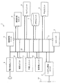
図1は本実施の形態が適用される画像形成装置1の全体構成の一例を示した図である。図1に示す画像形成装置1は、各色の画像データ(画像情報)に基づき画像形成を行う画像形成機能部の一例としての画像形成ユニット2、原稿上の画像を読み取って画像データを生成し画像形成ユニット2に送る制御機能部の一例としての画像読取ユニット3を備えている。また、ユーザからの操作入力の受付やユーザに対する各種情報の表示を行う制御機能部の一例としてのユーザインターフェース(UI)ユニット4、例えば公衆電話回線を介して画像情報の送受信を行う制御機能部の一例としてのファクシミリ(FAX)ユニット5を備えている。
さらに、画像形成装置1は、画像形成ユニット2(画像形成装置本体)に外付けで接続され、画像形成ユニット2に用紙Pを供給する制御機能部の一例としてのトレイユニット6、例えばハードディスクドライブ(HDD)やフラッシュメモリ等で構成される外部記憶装置であるメモリユニット7を備えている。またさらに、画像形成装置1全体の動作や通信回線を介した通信等を制御する制御手段の一例としてのシステム制御ユニット8、各部に電力を供給する電力供給ユニット9を備えている。
また、画像形成装置1は、用紙Pへの両面印刷時に使用される両面搬送路R2を構成する制御機能部の一例としての両面ユニット10、手差し用紙収容部からの用紙搬送経路R3を構成する制御機能部の一例としての手差しユニット11、画像形成ユニット2にて画像形成された後の用紙Pに対して綴じ等の後処理を行う制御機能部の一例としての後処理ユニット12を備えている。
Embodiments of the present invention will be described below in detail with reference to the accompanying drawings.
<Overall description of image forming apparatus>
FIG. 1 is a diagram illustrating an example of the overall configuration of an
Further, the
The
〈画像形成ユニットの説明〉
図1に示すように、画像形成ユニット2は、一定の間隔を置いて並列的に配置された4つの画像形成モジュール30Y,30M,30C,30K(以下、画像形成モジュール30)を備えている。各画像形成モジュール30には、構成要素の一例である画像形成機構部(後段図3の画像形成機構部24)として、静電潜像を形成してトナー像を保持する感光体ドラム31、感光体ドラム31の表面を帯電する帯電器32、帯電器32によって帯電された感光体ドラム31を画像データに基づいて露光する露光器33、感光体ドラム31上に形成された静電潜像を現像する現像器34、転写後の感光体ドラム31表面を清掃するクリーナ35が配置されている。
そして、各画像形成モジュール30は、それぞれがイエロー(Y)、マゼンタ(M)、シアン(C)、黒(K)のトナー像を形成する。
<Description of image forming unit>
As shown in FIG. 1, the
Each image forming module 30 forms yellow (Y), magenta (M), cyan (C), and black (K) toner images.
さらに、画像形成ユニット2は、画像形成機構部として、各画像形成モジュール30の感光体ドラム31にて形成された各色トナー像が多重転写される中間転写ベルト36、各画像形成モジュール30による各色トナー像を中間転写ベルト36に順次転写(一次転写)する一次転写ロール37、中間転写ベルト36上に転写された重畳トナー像を記録材(記録紙)である用紙Pに一括転写(二次転写)する二次転写ロール38、二次転写されたトナー画像を用紙Pに定着する定着器39を備えている。
また、画像形成ユニット2は、用紙P1を収容する用紙収容容器41を備えている。また、用紙収容容器41から用紙P1を用紙搬送経路R1に繰り出す構成要素の一例としての給紙機構部42、用紙収容容器41からの用紙P1やトレイユニット6からの用紙Pを用紙搬送経路R1に沿って搬送する構成要素の一例としての用紙搬送機構部43を備えている。
そして、画像形成ユニット2は、画像読取ユニット3からの画像データ、システム制御ユニット8が通信手段(後段図2の外部LAN14)を介して取得した印刷ジョブデータ、FAXユニット5にて受信したファクシミリデータ(画像情報)に基づいて、用紙収容容器41、トレイユニット6、および手差しユニット11に収容された用紙Pの片面に画像を形成する。また、両面ユニット10を用いて両面に画像を形成する。そして、画像形成された用紙Pを後処理ユニット12に搬送する。
Further, the
Further, the
The
〈画像読取ユニットの説明〉
画像読取ユニット3は、原稿上の画像を読み取って例えばR,G,B各色信号(画像データ)を生成する構成要素の一例としての画像読取機構部3A、画像読取機構部3Aにて原稿の片面が読み取られるように原稿を搬送する構成要素の一例としての片面原稿搬送機構部3B、画像読取機構部3Aにて原稿の両面が読み取られるように原稿を搬送する構成要素の一例としての両面原稿搬送機構部3Cを備えている。
そして、画像読取ユニット3は、原稿の片面または両面から画像を読み取って画像データを生成し、生成した画像データを画像形成ユニット2に送信する。
<Description of image reading unit>
The
Then, the
〈トレイユニットの説明〉
トレイユニット6は、上下方向に縦列的に配置された構成要素の一例としての3つのサブトレイ機構部6A〜6Cと、サブトレイ機構部6A〜6Cに横列して配置された構成要素の一例としての大容量のサブトレイ機構部6Dとを備えている。サブトレイ機構部6Aは、用紙P2を収容し、用紙P2を画像形成ユニット2に供給する。サブトレイ機構部6Bは、用紙P3を収容し、サブトレイ機構部6Aを通って用紙P3を画像形成ユニット2に供給する。サブトレイ機構部6Cは、用紙P4を収容し、サブトレイ機構部6Aおよびサブトレイ機構部6Bを通って用紙P4を画像形成ユニット2に供給する。サブトレイ機構部6Dは、用紙P5を収容し、用紙P5を画像形成ユニット2に供給する。
そして、トレイユニット6は、UIユニット4にてユーザの操作入力により指定された用紙Pや、システム制御ユニット8が取得した印刷ジョブデータにて指定された用紙Pをサブトレイ機構部6A〜6Dの何れかから画像形成ユニット2に供給する。
<Description of tray unit>
The tray unit 6 includes three sub-tray mechanism units 6A to 6C as an example of components arranged in a column in the vertical direction, and a large example of components arranged in a row in the sub-tray mechanism units 6A to 6C. And a sub-tray mechanism 6D having a capacity. The sub-tray mechanism 6A accommodates the paper P2 and supplies the paper P2 to the
Then, the tray unit 6 receives the paper P designated by the user's operation input in the
〈後処理ユニットの説明〉
後処理ユニット12は、画像形成ユニット2にて画像形成された後の用紙Pに2穴や4穴等の穴あけ(パンチ)を施す構成要素の一例としてのパンチ機構部12A、用紙Pに対して内三折り(C折り)や外三折り(Z折り)等の折り処理を施す構成要素の一例としての折り機構部12Bを備えている。また、用紙Pを複数枚集積させた用紙束の端部にステープル綴じ(端綴じ)を実行する構成要素の一例としての端綴じ機構部12C、用紙Pを複数枚集積させた用紙束の中央部分にステープル綴じ(中綴じ)を実行する構成要素の一例としての中綴じ機構部12Dを備えている。
そして、後処理ユニット12は、UIユニット4にてユーザの操作入力により指定された処理や、システム制御ユニット8が取得した印刷ジョブデータにて指定された処理を、画像形成ユニット2にて画像形成された後の用紙Pに施す。
<Description of post-processing unit>
The
Then, the
〈画像形成装置の通信系統および電力供給系統の説明〉
次の図2は、図1に示す画像形成装置1の通信系統と電力供給系統とを説明する図である。本実施の形態では、画像形成機能部である画像形成ユニット2と、制御機能部である画像読取ユニット3、UIユニット4、FAXユニット5、トレイユニット6、メモリユニット7、両面ユニット10、手差しユニット11、後処理ユニット12と、さらにはシステム制御ユニット8とが、機内LAN(Local Area Network)13に接続されている。本実施の形態では、各ユニット間を1本のバス(機内LAN13)に接続し、ユニット間の通信を実現している。それにより、システム制御ユニット8は、他のユニットを統合的に制御する。
また、システム制御ユニット8は、外部の機器(外部機器)と外部LAN14によって接続されている。それにより、システム制御ユニット8は、外部LAN14を介して外部機器から送られた印刷ジョブデータを、機内LAN13を介して画像形成ユニット2やメモリユニット7に送る。
さらに、画像形成装置1の各ユニット(画像形成ユニット2、画像読取ユニット3、UIユニット4、FAXユニット5、トレイユニット6、メモリユニット7、システム制御ユニット8、両面ユニット10、手差しユニット11、後処理ユニット12)には電力ライン15が接続されており、この電力ライン15に接続されている電力供給ユニット9を介して電力が供給される。電力供給ユニット9は、常夜電源として、予め定めた電圧(24V)の電力を常時供給する。
<Description of communication system and power supply system of image forming apparatus>
FIG. 2 is a diagram for explaining the communication system and the power supply system of the
The
Further, each unit of the image forming apparatus 1 (
〈各ユニット内での電源供給・停止制御の説明〉
各ユニット内で行われる電源供給・停止の制御について、画像形成ユニット2を代表例として説明する。
図3は、画像形成ユニット2の機能構成を説明する図である。画像形成機能部である画像形成ユニット2は、画像形成ユニット2の全体を制御する画像形成制御部20を備えている。また、各機構部(画像形成機構部24、給紙機構部42、用紙搬送機構部43)を個別に制御するサブ制御部として、画像形成機構部24を制御するプロセス制御部21、給紙機構部42を制御する給紙制御部22、および用紙搬送機構部43を制御する用紙搬送制御部23を備えている。また、電源部として、画像形成ユニット2内に電力を供給する画像形成電源部29を備えている。
画像形成制御部20は、機内LAN13により接続されたシステム制御ユニット8の制御に従って、ユニット内LAN(Local Area Network)16により接続された各サブ制御部(プロセス制御部21、給紙制御部22、用紙搬送制御部23)および画像形成電源部29を制御する。
<Description of power supply / stop control in each unit>
The power supply / stop control performed in each unit will be described using the
FIG. 3 is a diagram illustrating a functional configuration of the
The image forming
また、画像形成制御部20は、システム制御ユニット8による制御の下で、画像形成ユニット2の電源モード(画像形成ユニット2の動作状態)の遷移を制御する。すなわち、画像形成制御部20は画像形成電源部29を制御して、システム制御ユニット8によって設定された(i)電力供給を停止するスリープモード、(ii)各制御部への制御電力5Vだけを供給するスタンバイモード、(iii)制御電力5Vおよび各機構部への稼働電力24Vを供給するジョブモード等の電源モードを画像形成ユニット2に設定する。
さらに、画像形成制御部20は、電力供給を制御する制御手段の一例であるシステム制御ユニット8による制御の下で、スリープモードからの復帰時における各制御部への制御電力5Vの供給・停止および各機構部への稼働電力24Vの供給・停止を制御する。したがって、画像形成制御部20も、電力供給を制御する制御手段の一例として機能する。
Further, the image forming
Further, the image forming
画像形成電源部29は、電力供給ユニット9から常夜電源として予め定めた電圧(24V)の電力が電力ライン15を介して常時供給される。そして、画像形成電源部29は、画像形成制御部20にて設定される電源モードやスリープモードからの復帰時に設定される電力供給・停止指示に応じて、DC−DCコンバータにより低電圧化した制御電力(5V)を制御用電力ライン17を介して画像形成制御部20や各サブ制御部に供給する(電力供給状態)。また、稼働電力ライン18を介して稼働電力(24V)を各機構部や給紙検出部25Bに供給する(電力供給状態)。さらに、制御電力(5V)も稼働電力(24V)も停止する状態(電力停止状態)を設定する。
The image forming
なお、画像形成ユニット2以外においても、制御機能部である画像読取ユニット3、UIユニット4、FAXユニット5、トレイユニット6、メモリユニット7、両面ユニット10、手差しユニット11、後処理ユニット12は、システム制御ユニット8による制御の下で、同様の電源モードによる動作状態の制御、およびスリープモードからの復帰時における電力供給・停止の制御が行われる。
In addition to the
〈スリープモードからの復帰時における各ユニットの電力供給・停止の説明〉
本実施の形態の画像形成装置1においては、スリープモードから復帰する際に、例えばユーザによって予め定められたユニットおよび/またはユニット内の機構部へは電力供給を行い、それ以外のユニットおよび/またはユニット内の機構部へは電力供給を停止状態に維持する。それにより、スリープモードからの復帰時に画像形成装置1を機能させるのに必要なユニットやユニット内の機構部には電力供給されるが、スリープモードからの復帰時に画像形成装置1を機能させるのに不必要なユニットやユニット内の機構部には電力供給の停止状態が維持される。それによって、画像形成装置1で消費される電力の低減が図られる。
<Description of power supply / stop of each unit when returning from sleep mode>
In the
図4は、画像形成装置1をスリープモードから復帰させる場合に、システム制御ユニット8が各ユニットへの電力供給・停止の制御を行う際の処理の手順の一例を示したフローチャートである。
例えばUIユニット4に配置されたスリープモードからの復帰ボタンがユーザによってオンされると、システム制御ユニット8がスリープモードから復帰する(ステップ101)。そして、システム制御ユニット8は、画像形成装置1をスリープモードから復帰させる際に画像形成装置1に設定する機能内容について、例えばユーザによる事前設定(デフォルト設定)が存在するか否かを判定する(ステップ102)。
ここで、ユーザによる事前設定(デフォルト設定)は、UIユニット4からの事前のユーザ入力により、システム制御ユニット8の記憶部(例えば、後段図9の不揮発性メモリ104)に記憶(登録)される。したがって、UIユニット4およびシステム制御ユニット8は、画像形成機能部およびの制御機能部の一または複数の指定を受け付ける指定受付手段としても機能する。
FIG. 4 is a flowchart illustrating an example of a processing procedure when the
For example, when the return button from the sleep mode arranged in the
Here, the pre-setting (default setting) by the user is stored (registered) in the storage unit (for example, the
ステップ102にてデフォルト設定が存在する場合には(ステップ102でYes)、システム制御ユニット8は、デフォルト設定された機能内容に対応する画像形成機能部である画像形成ユニット2や制御機能部である各ユニットに対して、制御電力(5V)および稼働電力(24V)による電力供給状態(ON)の設定を指示する(ステップ103)。その一方で、デフォルト設定された機能に対応しない画像形成ユニット2や各ユニットに対しては、制御電力および稼働電力に関する電力停止状態(OFF)の設定を指示する(ステップ104)。
このように、デフォルト設定を予め登録しておくことで、スリープモードからの復帰処理の迅速化が図られる。
If the default setting exists in step 102 (Yes in step 102), the
Thus, by registering the default settings in advance, it is possible to speed up the return process from the sleep mode.
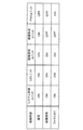
ここで、図5は、デフォルト設定された機能内容が「複写」、「画像読取」、「ファクシミリ」である場合に画像形成ユニット2および各ユニットに設定される電力供給状態(ON)および電力停止状態(OFF)の組み合わせの一例を示した図である。システム制御ユニット8は、この図5に一例として示した画像形成ユニット2および各ユニットにおけるON/OFF設定の組み合わせを機能内容に対応付けて、例えばシステム制御ユニット8の記憶部(例えば、後段図9のROM103)にテーブルとして保持する。そして、システム制御ユニット8は、スリープモードから復帰した際に、保持するテーブルに基づき、デフォルト設定された機能内容に対応して動作する(対応する)画像形成ユニット2および各ユニットに対して、制御電力および稼働電力に関するONの設定を指示する。一方、デフォルト設定された機能内容に対応して動作しない(対応しない)画像形成ユニット2および各ユニットに対しては、制御電力および稼働電力に関するOFFの設定を指示する。
なお、「複写」、「画像読取」、「ファクシミリ」以外の例えば「プリント」機能は、例えば外部LAN14を介して外部機器から印刷ジョブデータが送られた場合には必ず設定される。したがって、スリープモードから復帰させる際のデフォルト設定の如何に拘わらず、印刷ジョブデータが送られた場合には「プリント」機能に対応して動作する画像形成ユニット2および各ユニットにおいて制御電力および稼働電力に関する電力供給状態(ON)が必ず設定される。
Here, FIG. 5 shows the power supply state (ON) and power stop set for the
For example, “print” functions other than “copy”, “image reading”, and “facsimile” are always set when print job data is sent from an external device via the
次に、ステップ102にてデフォルト設定が存在しない場合には(ステップ102でNo)、システム制御ユニット8は、UIユニット4をスリープモードから復帰させる(ステップ105)。すなわち、デフォルト設定が存在しない場合には、システム制御ユニット8は、「複写」、「画像読取」、「ファクシミリ」の何れの機能内容においても共通に使用される制御機能部(ここではUIユニット4)を予め定めておき、これをスリープモードから復帰させておく。それにより、何れの機能内容が選択された場合にでも、スリープモードからの復帰処理の短縮化が図られる。
そして、システム制御ユニット8は、UIユニット4に対してスリープモードから復帰させる際に設定する機能内容の表示を指示する(ステップ106)。それにより、UIユニット4は、スリープモードから復帰させる際に設定する機能内容を表示する。
なお、ステップ102にてデフォルト設定が存在しない場合に機能内容の表示を指示する構成の他に、デフォルト設定として、機能内容の表示を行う設定を選択できる構成としてもよい。
Next, when there is no default setting in step 102 (No in step 102), the
Then, the
In addition to the configuration in which the display of the function contents is instructed when there is no default setting in
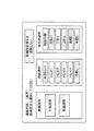
ここで、図6は、UIユニット4にてユーザに提示する選択可能な機能内容の一例を示した図である。ユーザは、UIユニット4から図6に一例として示した機能内容の何れかを選択する。すなわち、ユーザは、UIユニット4から例えば「複写」、「画像読取」、「ファクシミリ」の何れかを選択する。
Here, FIG. 6 is a diagram showing an example of selectable function contents presented to the user by the
UIユニット4にてスリープモードから復帰させる際に設定する機能内容が選択されると(ステップ107でYes)、システム制御ユニット8は、選択された機能内容に関する詳細設定項目の表示を指示する(ステップ108)。それにより、UIユニット4は、選択された機能内容に関する詳細設定項目を表示する。
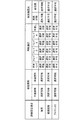
ここで、図7は、UIユニット4にてユーザに提示する選択された機能内容(複写)に関する詳細設定項目の一例を示した図である。ユーザは、UIユニット4から図7に一例として示した詳細設定項目の何れかを選択するか、または詳細設定項目を選択しないを設定する。
また、次の図8は、選択された機能内容に対応して選択可能な詳細設定項目の一例を示した図である。図7では、選択された機能内容が「複写」である場合においてUIユニット4にてユーザに提示する詳細設定項目の一例を示したが、選択された機能内容が「画像読取」、「ファクシミリ」である場合には、図8に示した選択可能な詳細設定項目が選択された機能内容に対応して表示される。
When the function content to be set when the
Here, FIG. 7 is a diagram showing an example of detailed setting items related to the selected function content (copy) presented to the user by the
FIG. 8 is a diagram showing an example of detailed setting items that can be selected according to the selected function content. FIG. 7 shows an example of the detailed setting items presented to the user in the
システム制御ユニット8は、UIユニット4にて機能内容に関する詳細設定項目の何れか一または複数が選択されると(ステップ109でYes)、ステップ107にて選択された機能内容に対応するユニットと、ステップ109にて選択された一または複数の詳細設定項目に対応するユニットおよび機構部とについて電力供給状態(ON)の設定を指示する(ステップ110)。
例えば、ステップ107にて機能内容として「複写」が選択され、ステップ109にて詳細設定項目の何れかが選択された場合には、「複写」に対応するユニット、すなわち、図5に示した画像読取ユニット3と画像形成ユニット2とが、システム制御ユニット8およびUIユニット4に加えて電力供給状態(ON)に設定される。
加えて、選択された詳細設定項目に対応するユニットまたはユニット内の機構部がONに設定される。具体的には、例えば図7に示した「片面読取」が選択された場合には、画像読取ユニット3の片面原稿搬送機構部3B(図1参照)が電力供給状態(ON)に設定される。また、「両面読取」が選択された場合には、画像読取ユニット3の両面原稿搬送機構部3CがONに設定される。また、「本体トレイ」が選択された場合には、トレイユニット6が電力停止状態(OFF)に設定される。「トレイ1」〜「トレイ4」の何れかが選択された場合には、トレイユニット6の中の「トレイ1」〜「トレイ4」に対応するサブトレイ機構部6A〜6DがONに設定される。「手差し」が選択された場合には、手差しユニット11がONに設定される。「両面印刷」が選択された場合には、両面ユニット10がONに設定される。「穴あけ」、「C折り」、「Z折り」、「端綴じ」、「中綴じ」の何れかが選択された場合には、後処理ユニット12がONに設定される。
When any one or more of the detailed setting items related to the function contents are selected in the UI unit 4 (Yes in Step 109), the
For example, when “Copy” is selected as the function content in Step 107 and any of the detailed setting items is selected in Step 109, the unit corresponding to “Copy”, that is, the image shown in FIG. The
In addition, the unit corresponding to the selected detailed setting item or the mechanism section in the unit is set to ON. Specifically, for example, when “single-sided reading” shown in FIG. 7 is selected, the single-sided document
一方、UIユニット4にて機能内容に関する詳細設定項目が選択されない場合には(ステップ109でNo)、システム制御ユニット8は、ステップ107にて選択された機能内容に対応するユニットに対する電力供給状態(ON)の設定を指示する(ステップ111)。
例えば、ステップ107にて機能内容として「複写」が選択され、ステップ109にて詳細設定項目が選択されない場合には、「複写」に対応するユニット、すなわち、図5に示した画像読取ユニット3と画像形成ユニット2とが、システム制御ユニット8およびUIユニット4に加えて電力供給状態(ON)に設定される。
On the other hand, when the detailed setting item related to the function content is not selected in the UI unit 4 (No in Step 109), the
For example, if “Copy” is selected as the function content in Step 107 and the detailed setting item is not selected in Step 109, the unit corresponding to “Copy”, that is, the
このように、画像形成装置1をスリープモードから復帰させる際には、例えばユーザによって予め定められたユニットおよび/または機構部へは電力供給を行い、それ以外のユニットおよび/またはユニット内の機構部へは電力供給を停止状態に維持する。それにより、スリープモードからの復帰時に画像形成装置1を機能させるのに必要なユニットやユニット内の機構部には電力供給され、不必要なユニットやユニット内の機構部には電力供給が停止状態に維持される。その結果として、画像形成装置1で消費される電力の低減が図られる。
As described above, when the
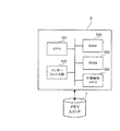
図9は、システム制御ユニット8のハードウェア構成を示した図である。図9に示したように、システム制御ユニット8は、各ユニットに対する電力供給制御や電源モードの遷移制御を実行するに際して、予め定められたプログラムに従ってデジタル演算処理を実行する演算手段の一例としてのCPU101、CPU101の作業領域として用いられるRAM102、CPU101により実行されるプログラム等にて用いられる設定値等のデータが格納されたROM103、書き換え可能で電源供給が途絶えた場合にもデータを保持するEEPROMやフラッシュメモリ等の不揮発性メモリ104、システム制御ユニット8やユニット内LAN16を介して接続された各サブ制御部との信号の入出力を制御するインターフェース部105を備えている。
FIG. 9 is a diagram showing a hardware configuration of the
ここで、メモリユニット7にはシステム制御ユニット8により実行されるプログラムが格納されており、システム制御ユニット8がこのプログラムを読み込むことによって、各ユニットに対する電力供給制御や電源モードの遷移制御が実行される。すなわち、各ユニットに対する電力供給制御や電源モードの遷移制御を実行するプログラム等が、例えばメモリユニット7としてのハードディスクやDVD−ROM等からシステム制御ユニット8のRAM102に読み込まれる。そして、RAM102に読み込まれたプログラムに基づいて、CPU101が各種処理を行う。このプログラムに関するその他の提供形態としては、予めROM103に格納された状態にて提供され、RAM102にロードされる形態がある。さらに、EEPROM等の書き換え可能なROM103を備えている場合には、システム制御ユニット8がセッティングされた後に、プログラムだけがROM103にインストールされ、RAM102にロードされる形態がある。また、インターネット等の外部LAN14を介してシステム制御ユニット8にプログラムが伝送され、システム制御ユニット8のROM103にインストールされ、RAM102にロードされる形態がある。
Here, the program executed by the
以上説明したように、本実施の形態の画像形成装置1では、画像形成装置1をスリープモードから復帰させる際には、スリープモードから復帰する際に予め定められたユニットおよび/またはユニット内の機構部へは電力供給を行い、それ以外のユニットおよび/またはユニット内の機構部へは電力供給を停止状態に維持する。それにより、スリープモードからの復帰時に画像形成装置1を機能させるのに必要なユニットやユニット内の機構部には電力供給するが、スリープモードからの復帰時に画像形成装置1を機能させるのに不必要なユニットやユニット内の機構部には電力供給を停止状態に維持される。それによって、画像形成装置1で消費される電力の低減が図られる。
As described above, in the
1…画像形成装置、2…画像形成ユニット、3…画像読取ユニット、4…ユーザインターフェース(UI)ユニット、5…ファクシミリ(FAX)ユニット、6…トレイユニット、6A〜6D…サブトレイ機構部、7…メモリユニット、8…システム制御ユニット、9…電力供給ユニット、10…両面ユニット、11…手差しユニット、12…後処理ユニット、13…機内LAN、14…外部LAN、15…電力ライン、16…ユニット内LAN、17…制御用電力ライン、18…稼働電力ライン、20…画像形成制御部、29…画像形成電源部
DESCRIPTION OF
Claims (10)
前記画像形成機能部との間で画像形成に関連する情報または信号の送受信を行う複数の制御機能部と、
前記画像形成機能部および複数の前記制御機能部に対する電力供給を制御する制御手段と、
前記画像形成機能部および複数の前記制御機能部の一または複数の指定を受け付ける指定受付手段とを備え、
前記制御手段は、前記画像形成機能部および複数の前記制御機能部に設定された電力停止状態を電力供給状態に復帰させる際に、前記指定受付手段にて指定された当該画像形成機能部および/または当該制御機能部を電力供給状態に設定することを特徴とする画像形成装置。 An image forming function unit for forming an image based on image information;
A plurality of control function units for transmitting and receiving information or signals related to image formation with the image forming function unit;
Control means for controlling power supply to the image forming function section and the plurality of control function sections;
A designation receiving unit that receives one or more designations of the image forming function unit and the plurality of control function units;
When the control unit returns the power stop state set in the image forming function unit and the plurality of control function units to a power supply state, the control unit and the image forming function unit specified by the specification receiving unit and / or Alternatively, the control function unit is set in a power supply state.
前記画像形成機能部および複数の前記制御機能部の一または複数の指定を受け付ける指定受付手段とを備え、
前記制御手段は、前記画像形成機能部および複数の前記制御機能部に設定された電力停止状態を電力供給状態に復帰させる際に、前記指定受付手段にて指定された当該画像形成機能部および/または当該制御機能部を電力供給状態に設定することを特徴とする制御装置。 Control means for controlling power supply to an image forming function unit that forms an image based on image information and a plurality of control function units that transmit and receive information or signals related to image formation between the image forming function unit; ,
A designation receiving unit that receives one or more designations of the image forming function unit and the plurality of control function units;
When the control unit returns the power stop state set in the image forming function unit and the plurality of control function units to a power supply state, the control unit and the image forming function unit specified by the specification receiving unit and / or Or the control function part is set to an electric power supply state, The control apparatus characterized by the above-mentioned.
画像情報に基づき画像形成を行う画像形成機能部と、当該画像形成機能部との間で画像形成に関連する情報または信号の送受信を行う複数の制御機能部とから一または複数の指定を受け付ける機能と、
前記画像形成機能部および複数の前記制御機能部に設定された電力停止状態を電力供給状態に復帰させる際に、指定された当該画像形成機能部および/または当該制御機能部を電力供給状態に設定する機能と
を実現させることを特徴とするプログラム。 On the computer,
A function that accepts one or more designations from an image forming function unit that performs image formation based on image information and a plurality of control function units that transmit and receive information or signals related to image formation between the image forming function unit When,
When the power stop state set in the image forming function unit and the plurality of control function units is returned to the power supply state, the specified image forming function unit and / or the control function unit is set to the power supply state. A program characterized by realizing a function to perform.
Priority Applications (1)
| Application Number | Priority Date | Filing Date | Title |
|---|---|---|---|
| JP2008216369A JP5262433B2 (en) | 2008-08-26 | 2008-08-26 | Image forming apparatus, control apparatus, and program |
Applications Claiming Priority (1)
| Application Number | Priority Date | Filing Date | Title |
|---|---|---|---|
| JP2008216369A JP5262433B2 (en) | 2008-08-26 | 2008-08-26 | Image forming apparatus, control apparatus, and program |
Publications (2)
| Publication Number | Publication Date |
|---|---|
| JP2010056601A true JP2010056601A (en) | 2010-03-11 |
| JP5262433B2 JP5262433B2 (en) | 2013-08-14 |
Family
ID=42072109
Family Applications (1)
| Application Number | Title | Priority Date | Filing Date |
|---|---|---|---|
| JP2008216369A Expired - Fee Related JP5262433B2 (en) | 2008-08-26 | 2008-08-26 | Image forming apparatus, control apparatus, and program |
Country Status (1)
| Country | Link |
|---|---|
| JP (1) | JP5262433B2 (en) |
Cited By (3)
| Publication number | Priority date | Publication date | Assignee | Title |
|---|---|---|---|---|
| JP2011206965A (en) * | 2010-03-29 | 2011-10-20 | Kyocera Mita Corp | Image forming apparatus |
| JP2012078955A (en) * | 2010-09-30 | 2012-04-19 | Canon Inc | Information processing apparatus, power source control method thereof and power source control program |
| JP2012145871A (en) * | 2011-01-14 | 2012-08-02 | Fuji Xerox Co Ltd | Image forming apparatus and program |
Citations (4)
| Publication number | Priority date | Publication date | Assignee | Title |
|---|---|---|---|---|
| JPH08254922A (en) * | 1995-03-15 | 1996-10-01 | Ricoh Co Ltd | Image forming device |
| JP2003008794A (en) * | 2001-06-20 | 2003-01-10 | Ricoh Co Ltd | Facsimile composite machine |
| JP2004222234A (en) * | 2002-12-27 | 2004-08-05 | Ricoh Co Ltd | Image forming apparatus and energy saving control method for the same |
| JP2006217647A (en) * | 1995-06-09 | 2006-08-17 | Ricoh Co Ltd | Data communication apparatus |
-
2008
- 2008-08-26 JP JP2008216369A patent/JP5262433B2/en not_active Expired - Fee Related
Patent Citations (4)
| Publication number | Priority date | Publication date | Assignee | Title |
|---|---|---|---|---|
| JPH08254922A (en) * | 1995-03-15 | 1996-10-01 | Ricoh Co Ltd | Image forming device |
| JP2006217647A (en) * | 1995-06-09 | 2006-08-17 | Ricoh Co Ltd | Data communication apparatus |
| JP2003008794A (en) * | 2001-06-20 | 2003-01-10 | Ricoh Co Ltd | Facsimile composite machine |
| JP2004222234A (en) * | 2002-12-27 | 2004-08-05 | Ricoh Co Ltd | Image forming apparatus and energy saving control method for the same |
Cited By (3)
| Publication number | Priority date | Publication date | Assignee | Title |
|---|---|---|---|---|
| JP2011206965A (en) * | 2010-03-29 | 2011-10-20 | Kyocera Mita Corp | Image forming apparatus |
| JP2012078955A (en) * | 2010-09-30 | 2012-04-19 | Canon Inc | Information processing apparatus, power source control method thereof and power source control program |
| JP2012145871A (en) * | 2011-01-14 | 2012-08-02 | Fuji Xerox Co Ltd | Image forming apparatus and program |
Also Published As
| Publication number | Publication date |
|---|---|
| JP5262433B2 (en) | 2013-08-14 |
Similar Documents
| Publication | Publication Date | Title |
|---|---|---|
| US11528373B2 (en) | Printing apparatus and control method for determining a print order of images on sheets based on a binding setting | |
| US8687234B2 (en) | Image forming apparatus | |
| JP2016114903A (en) | Image formation apparatus, image formation system and image formation control method | |
| JP6288005B2 (en) | Image forming apparatus, image forming management apparatus, and image forming method | |
| JP6435780B2 (en) | Image forming apparatus, image forming system, image forming control apparatus, and image forming method | |
| JP6045137B2 (en) | Image forming apparatus, image forming apparatus control method and program | |
| JP5262433B2 (en) | Image forming apparatus, control apparatus, and program | |
| JP2012027099A (en) | Image forming control device, image forming system, control method, and program | |
| JP2010130163A (en) | Image forming device, control device, and program | |
| JP2007025877A (en) | Power source supply unit | |
| JP5262384B2 (en) | Image forming apparatus, control apparatus, and program | |
| JP2015098096A (en) | Image forming device, and control method for image forming device | |
| JP2010052148A (en) | Image forming apparatus, controller, and program | |
| JP5540486B2 (en) | Image forming apparatus, control apparatus, and program | |
| JP2010056750A (en) | Image forming device, controller and program | |
| JP2010256470A (en) | Image forming apparatus and control structure | |
| JP2010054563A (en) | Image forming apparatus, control device and program | |
| JP2010056659A (en) | Image forming apparatus, controller, and program | |
| JP2010062901A (en) | Image forming system, image forming apparatus, and program | |
| JP2010066299A (en) | Printing control apparatus, printing control method, and program | |
| JP2003015478A (en) | Image forming device | |
| JP2011191424A (en) | Image forming apparatus, control method of image forming apparatus, and control program of image forming apparatus | |
| JP2011065072A (en) | Image forming apparatus and controlling structure | |
| JP5660518B2 (en) | Image forming apparatus and program | |
| JP2005323059A (en) | Image forming apparatus |
Legal Events
| Date | Code | Title | Description |
|---|---|---|---|
| A621 | Written request for application examination |
Free format text: JAPANESE INTERMEDIATE CODE: A621 Effective date: 20110809 |
|
| A977 | Report on retrieval |
Free format text: JAPANESE INTERMEDIATE CODE: A971007 Effective date: 20120821 |
|
| A131 | Notification of reasons for refusal |
Free format text: JAPANESE INTERMEDIATE CODE: A131 Effective date: 20120828 |
|
| A521 | Request for written amendment filed |
Free format text: JAPANESE INTERMEDIATE CODE: A523 Effective date: 20121022 |
|
| TRDD | Decision of grant or rejection written | ||
| A01 | Written decision to grant a patent or to grant a registration (utility model) |
Free format text: JAPANESE INTERMEDIATE CODE: A01 Effective date: 20130402 |
|
| A61 | First payment of annual fees (during grant procedure) |
Free format text: JAPANESE INTERMEDIATE CODE: A61 Effective date: 20130415 |
|
| R150 | Certificate of patent or registration of utility model |
Free format text: JAPANESE INTERMEDIATE CODE: R150 Ref document number: 5262433 Country of ref document: JP Free format text: JAPANESE INTERMEDIATE CODE: R150 |
|
| S533 | Written request for registration of change of name |
Free format text: JAPANESE INTERMEDIATE CODE: R313533 |
|
| R350 | Written notification of registration of transfer |
Free format text: JAPANESE INTERMEDIATE CODE: R350 |
|
| LAPS | Cancellation because of no payment of annual fees |