JP2010055851A - Support structure of headlamp and fuel tank - Google Patents
Support structure of headlamp and fuel tank Download PDFInfo
- Publication number
- JP2010055851A JP2010055851A JP2008217500A JP2008217500A JP2010055851A JP 2010055851 A JP2010055851 A JP 2010055851A JP 2008217500 A JP2008217500 A JP 2008217500A JP 2008217500 A JP2008217500 A JP 2008217500A JP 2010055851 A JP2010055851 A JP 2010055851A
- Authority
- JP
- Japan
- Prior art keywords
- headlamp
- fuel tank
- support structure
- joint
- lens
- Prior art date
- Legal status (The legal status is an assumption and is not a legal conclusion. Google has not performed a legal analysis and makes no representation as to the accuracy of the status listed.)
- Granted
Links
Images


Landscapes
- Lighting Device Outwards From Vehicle And Optical Signal (AREA)
- Non-Portable Lighting Devices Or Systems Thereof (AREA)
Abstract
Description
本発明は、ヘッドランプと燃料タンクの支持構造に関し、詳しくは、雨水等がランプハウジングとレンズとの接合部に進入するのを抑制することができるヘッドランプと燃料タンクの支持構造に関するものである。 The present invention relates to a support structure for a headlamp and a fuel tank, and more particularly to a support structure for a headlamp and a fuel tank that can prevent rainwater or the like from entering a joint between a lamp housing and a lens. .
従来のヘッドランプと燃料タンクの支持構造として、ヘッドランプ支持体にヘッドランプが取り付けられたものがある(例えば、特許文献1参照)。 As a conventional support structure for a headlamp and a fuel tank, there is one in which a headlamp is attached to a headlamp support (see, for example, Patent Document 1).
しかし、従来の技術では、ヘッドランプが枠体で構成されたヘッドランプ支持体の内部に収容されているため、問題がある。 However, the conventional technique has a problem because the headlamp is housed inside a headlamp support body formed of a frame.
上記従来技術では、次の問題が生じる。
《問題》 雨水等がランプハウジングとレンズとの接合部に進入しやすい。
ヘッドランプが枠体で構成されたヘッドランプ支持体の内部に収容されているため、降雨時に雨水がヘッドランプ支持体に導かれると、この雨水がヘッドランプ支持体からランプハウジングとレンズとの接合部に落下し、接合部に進入しやすい。また、給油時にこぼした燃料がヘッドランプ支持体に導かれると、この燃料がランプハウジングとレンズとの接合部に落下し、接合部に進入するおそれもある。
雨水や燃料がランプハウジングとレンズとの接合部に進入すると、この接合部にシール材や接着剤が用いられている場合には、これらの劣化や膨潤が生じる。また、雨水や燃料がランプハウジング内にまで進入すると、レンズの曇り等を引き起こすおそれがある。
In the above-described conventional technology, the following problem occurs.
<Problem> Rainwater or the like tends to enter the joint between the lamp housing and the lens.
Since the headlamp is housed inside the headlamp support composed of a frame, when rainwater is guided to the headlamp support during rainfall, the rainwater joins the lamp housing and the lens from the headlamp support. It is easy to fall into the joint and enter the joint. In addition, if fuel spilled during refueling is guided to the headlamp support, the fuel may fall to the joint between the lamp housing and the lens and enter the joint.
When rainwater or fuel enters the joint between the lamp housing and the lens, when a sealing material or an adhesive is used at the joint, the deterioration or swelling occurs. Further, if rainwater or fuel enters the lamp housing, the lens may become cloudy.
本発明は、上記問題点を解決することができるヘッドランプと燃料タンクの支持構造、すなわち、雨水等がランプハウジングとレンズとの接合部に進入するのを抑制することができるヘッドランプと燃料タンクの支持構造を提供することを課題とする。 The present invention is a headlamp and fuel tank support structure that can solve the above-described problems, that is, a headlamp and a fuel tank that can prevent rainwater or the like from entering the joint between the lamp housing and the lens. It is an object to provide a support structure.
請求項1に係る発明の発明特定事項は、次の通りである。
図2(A)に例示するように、ヘッドランプ支持体(1)にヘッドランプ(2)が取り付けられ、ヘッドランプ(2)はランプハウジング(3)の前部にレンズ(4)を取り付けて構成され、このヘッドランプ(2)の後方に燃料タンク(5)が配置され、この燃料タンク(5)から前方に取付フランジ(6)が突出され、この取付フランジ(6)がヘッドランプ支持体(1)に固定された、ヘッドランプと燃料タンクの支持構造であって、
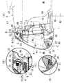
図1(A)、図2(A)(B)、図3に例示するように、ランプハウジング(3)とレンズ(4)との接合部(7)のうち、ヘッドランプ天井壁(8)に形成された接合部天井壁部分(9)の少なくとも一部が、燃料タンク(5)の取付フランジ(6)よりも高い位置に配置されている、ことを特徴とするヘッドランプと燃料タンクの支持構造。
Invention specific matters of the invention according to
As illustrated in FIG. 2A, the
As illustrated in FIGS. 1 (A), 2 (A), 2 (B), and 3, the headlamp ceiling wall (8) of the joint (7) between the lamp housing (3) and the lens (4). The headlamp and the fuel tank are characterized in that at least a part of the joint ceiling wall portion (9) formed on the fuel tank is disposed at a position higher than the mounting flange (6) of the fuel tank (5). Support structure.
(請求項1に係る発明)
《効果》 雨水等がランプハウジングとレンズとの接合部に進入するのを抑制することができる。
図1(A)、図2(A)(B)、図3に例示するように、ランプハウジング(3)とレンズ(4)との接合部(7)のうち、ヘッドランプ天井壁(8)に形成された接合部天井壁部分(9)の少なくとも一部が、燃料タンク(5)の取付フランジ(6)よりも高い位置に配置されているので、降雨時に雨水が燃料タンク(5)の壁を伝って取付フランジ(6)やヘッドランプ支持体(1)に導かれても、雨水がランプハウジング(3)とレンズ(4)との接合部(7)に進入するのを抑制することができる。また、給油時にこぼした燃料が燃料タンク(5)の壁を伝って取付フランジ(6)やヘッドランプ支持体(1)に導かれても、燃料がランプハウジング(3)とレンズ(4)との接合部(7)に進入するのを抑制することができる。
(Invention according to Claim 1)
<Effect> Rain water or the like can be prevented from entering the joint between the lamp housing and the lens.
As illustrated in FIGS. 1 (A), 2 (A), 2 (B), and 3, the headlamp ceiling wall (8) of the joint (7) between the lamp housing (3) and the lens (4). At least a part of the joint ceiling wall portion (9) formed at the position is higher than the mounting flange (6) of the fuel tank (5). Even if it is guided to the mounting flange (6) and the headlamp support (1) through the wall, rainwater can be prevented from entering the joint (7) between the lamp housing (3) and the lens (4). Can do. In addition, even if fuel spilled during refueling travels along the wall of the fuel tank (5) and is guided to the mounting flange (6) and the headlamp support (1), the fuel can be removed from the lamp housing (3) and the lens (4). It can suppress entering into the junction part (7).
(請求項2に係る発明)
請求項1に係る発明の効果に加え、次の効果を奏する。
《効果》 簡単な構造のヘッドランプ支持体で燃料タンクの支持を行うことができる。
図1(A)に例示するように、ヘッドランプ支持体(1)が枠体(10)を備え、枠体(10)が横向きの上枠部(11)と立向きの左右の横側枠部(12)(12)とを備え、図1(A)、図2(A)(B)、図3に例示するように、上枠部(11)にタンク固定手段(13)で、燃料タンク(5)の取付フランジ(6)が固定されているので、簡単な構造のヘッドランプ支持体(1)で燃料タンク(5)の支持を行うことができる。
(Invention according to Claim 2)
In addition to the effect of the invention according to
<Effect> The fuel tank can be supported by a headlamp support having a simple structure.
As illustrated in FIG. 1 (A), the headlamp support (1) includes a frame (10), and the frame (10) has a horizontal upper frame (11) and a left and right horizontal side frame. Parts (12) and (12), as illustrated in FIGS. 1 (A), 2 (A), (B), and 3, the tank fixing means (13) is attached to the upper frame part (11). Since the mounting flange (6) of the tank (5) is fixed, the fuel tank (5) can be supported by the headlamp support (1) having a simple structure.
(請求項3に係る発明)
請求項2に係る発明の効果に加え、次の効果を奏する。
《効果》 ランプハウジングとレンズとの接合部への雨水等の進入抑制機能が高い。
図1(A)に例示するように、ランプハウジング(3)とレンズ(4)との接合部(7)のうち、左右のヘッドランプ横側壁(14)(14)に形成された左右の接合部横側壁部分(15)(15)の少なくとも上半部が、正面前方から見て、ヘッドランプ支持体(1)の左右の横側枠部(12)(12)よりも外寄りに配置されているので、ヘッドランプ支持体(1)の左右の横側枠部(12)(12)を伝う雨水や燃料が、左右の接合部横側壁部分(15)(15)の上半部に侵入しにくい。このため、ランプハウジング(3)とレンズ(4)との接合部(7)への雨水等の進入抑制機能が高い。
(Invention according to claim 3)
In addition to the effect of the invention according to
<Effect> It has a high function of suppressing the entry of rainwater or the like into the joint between the lamp housing and the lens.
As illustrated in FIG. 1A, the left and right joints formed on the left and right headlamp lateral side walls (14) and (14) of the joint (7) between the lamp housing (3) and the lens (4). At least the upper half of the horizontal side wall portions (15), (15) is disposed outside the left and right horizontal frame portions (12), (12) of the headlamp support (1) when viewed from the front front. Because of this, rainwater and fuel that travel along the left and right side frames (12) and (12) of the headlamp support (1) enter the upper half of the left and right joint side walls (15) and (15). Hard to do. For this reason, the function of suppressing entry of rainwater or the like into the joint (7) between the lamp housing (3) and the lens (4) is high.
(請求項4に係る発明)
請求項2または請求項3に係る発明の効果に加え、次の効果を奏する。
《効果》 ランプハウジングとレンズとの接合部への雨水等の進入抑制機能が高い。
図2(A)に例示するように、ランプハウジング(3)とレンズ(4)との接合部(7)のうち、左右のヘッドランプ横側壁(14)(14)に形成された左右の接合部横側壁部分(15)(15)の少なくとも下半部が、ヘッドランプ支持体(1)の左右の横側枠部(12)(12)よりも前寄りに配置されているので、ヘッドランプ支持体(1)の左右の横側枠部(12)(12)を伝う雨水や燃料が、左右の接合部横側壁部分(15)(15)の下半部に侵入しにくい。このため、ランプハウジング(3)とレンズ(4)との接合部(7)への雨水等の進入抑制機能が高い。
(Invention of Claim 4)
In addition to the effect of the invention according to
<Effect> It has a high function of suppressing the entry of rainwater or the like into the joint between the lamp housing and the lens.
As illustrated in FIG. 2A, the left and right joints formed on the left and right headlamp side walls (14) and (14) of the joint (7) between the lamp housing (3) and the lens (4). Since at least the lower half of the horizontal side wall portions (15), (15) is disposed in front of the left and right horizontal frame portions (12), (12) of the headlamp support (1), the headlamp Rainwater and fuel traveling along the left and right lateral frame portions (12) and (12) of the support (1) are unlikely to enter the lower half of the left and right joint lateral wall portions (15) and (15). For this reason, the function of suppressing entry of rainwater or the like into the joint (7) between the lamp housing (3) and the lens (4) is high.
(請求項5に係る発明)
請求項2から請求項4のいずれかに係る発明の効果に加え、次の効果を奏する。
《効果》 ヘッドランプのレンズがヘッドランプ支持体の前方に突出する寸法を小さくすることができる。
図2(A)、図3に例示するように、接合部天井壁部分(9)が上枠部(11)の真上に配置され、ランプハウジング(3)がヘッドランプ支持体(1)の枠内を貫通しているので、ヘッドランプ(2)のレンズ(4)がヘッドランプ支持体(1)の前方に突出する寸法を小さくすることができる。
(Invention according to claim 5)
In addition to the effects of the invention according to any one of
<Effect> It is possible to reduce the size of the headlamp lens protruding forward of the headlamp support.
As illustrated in FIG. 2A and FIG. 3, the joint ceiling wall portion (9) is disposed immediately above the upper frame portion (11), and the lamp housing (3) is provided on the headlamp support (1). Since it penetrates through the frame, it is possible to reduce the size of the lens (4) of the headlamp (2) protruding forward of the headlamp support (1).
(請求項6に係る発明)
請求項5に係る発明の効果に加え、次の効果を奏する。
《効果》 ランプハウジングとレンズとの接合部への雨水等の進入抑制機能が高い。
図2(A)に例示するように、ヘッドランプ支持体(1)の左右の横側枠部(12)(12)は後に向かって下り傾斜し、ランプハウジング(3)とレンズ(4)との接合部(7)のうち、左右のヘッドランプ横側壁(14)に形成された左右の接合部横側壁部分(15)(15)は前に向かって下り傾斜しているので、ランプハウジング(3)とレンズ(4)との接合部(7)の左右の接合部横側壁部分(15)(15)は下に行くほど、ヘッドランプ支持体(1)の左右の横側枠部(12)(12)から遠ざかり、ヘッドランプ支持体(1)の左右の横側枠部(12)(12)を伝う雨水や燃料が、左右の接合部横側壁部分(15)(15)の下半部に侵入しにくい。このため、ランプハウジング(3)とレンズ(4)との接合部(7)への雨水等の進入抑制機能が高い。
(Invention of Claim 6)
In addition to the effect of the invention according to
<Effect> It has a high function of suppressing the entry of rainwater or the like into the joint between the lamp housing and the lens.
As illustrated in FIG. 2 (A), the left and right lateral frame portions (12), (12) of the headlamp support (1) are inclined downward toward the rear, and the lamp housing (3), the lens (4), Left and right side lamp side wall portions (15) and (15) formed on the left and right headlamp side wall (14) are inclined downward toward the front. 3) and the left and right joint side wall portions (15) and (15) of the joint portion (7) between the lens (4) and the left and right lateral frame portions (12) of the headlamp support (1) as it goes downward. ) (12), the rainwater and fuel that travels through the left and right lateral frames (12) and (12) of the headlamp support (1) are transferred to the lower half of the left and right joint lateral walls (15) and (15). Difficult to penetrate the part. For this reason, the function of suppressing entry of rainwater or the like into the joint (7) between the lamp housing (3) and the lens (4) is high.
(請求項7に係る発明)
請求項1から請求項6のいずれかに係る発明の効果に加え、次の効果を奏する。
《効果》 ランプハウジングとレンズとの接合部への雨水等の進入抑制機能が高い。
図2(B)に例示するように、接合部天井壁部分(9)がランプハウジング(3)とレンズ(4)との嵌合部(16)で構成され、この嵌合部(16)の嵌合隙間(17)の外側入口(18)が嵌合隙間(17)の前部に形成されているので、燃料タンク(5)の取付フランジ(6)から前向きに流れ出す雨水等が嵌合隙間(17)に進入しにくい。このため、ランプハウジング(3)とレンズ(4)との接合部(7)への雨水等の進入抑制機能が高い。
(Invention of Claim 7)
In addition to the effects of the invention according to any one of
<Effect> It has a high function of suppressing the entry of rainwater or the like into the joint between the lamp housing and the lens.
As illustrated in FIG. 2B, the joint ceiling wall portion (9) is constituted by a fitting portion (16) between the lamp housing (3) and the lens (4), and the fitting portion (16) Since the outer inlet (18) of the fitting gap (17) is formed in the front part of the fitting gap (17), rain water or the like flowing forward from the mounting flange (6) of the fuel tank (5) It is difficult to enter (17). For this reason, the function of suppressing entry of rainwater or the like into the joint (7) between the lamp housing (3) and the lens (4) is high.
(請求項8に係る発明)
請求項7に係る発明の効果に加え、次の効果を奏する。
《効果》 接合部天井壁部分からヘッドランプ内への雨水等の進入抑制機能が高い。
図2(B)に例示するように、嵌合部(16)がランプハウジング(3)に形成された嵌合溝(20)とレンズ(4)に形成された嵌入部分(22)とからなり、嵌合溝(20)の溝入口(23)が嵌合溝(20)の前端で開口され、この溝入口(23)からレンズ(4)の嵌入部分(22)が後向きに嵌入されているので、接合部天井壁部分(9)の嵌合隙間(17)がラビリンス状に形成され、この嵌合隙間(17)を雨水等が通過しにくく、接合部天井壁部分(9)からヘッドランプ(2)内への雨水等の進入抑制機能が高い。
(Invention of Claim 8)
In addition to the effect of the invention according to
<Effect> It has a high function of suppressing the entry of rainwater and the like from the joint ceiling wall into the headlamp.
As illustrated in FIG. 2 (B), the fitting portion (16) includes a fitting groove (20) formed in the lamp housing (3) and a fitting portion (22) formed in the lens (4). The groove inlet (23) of the fitting groove (20) is opened at the front end of the fitting groove (20), and the fitting portion (22) of the lens (4) is fitted backward from the groove inlet (23). Therefore, the fitting gap (17) of the joint ceiling wall portion (9) is formed in a labyrinth shape, and rainwater or the like hardly passes through the fitting gap (17), and the headlamp from the joint ceiling wall portion (9). (2) The function of preventing rainwater and the like from entering is high.
(請求項9に係る発明)
請求項1から請求項8のいずれかに係る発明の効果に加え、次の効果を奏する。
《効果》 ランプハウジングとレンズとの接合部への雨水等の進入抑制機能が高い。
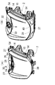
図2(B)に例示するように、接合部天井壁部分(9)の接合隙間(24)の外側入口(25)の後方で、ヘッドランプ天井壁(8)から上向きに立壁(26)が設けられ、図4(A)(B)、図5、図6(A)(B)に例示するように、この立壁(26)がヘッドランプ天井壁(8)に沿って横方向に連続形成されているので、燃料タンク(5)側からランプハウジング(3)とレンズ(4)との接合部(7)の外側入口(25)に近づこうとする雨水や燃料は、立壁(26)に遮られ、ヘッドランプ(2)の接合部天井壁部分(9)に形成された接合隙間(24)には侵入しにくい。このため、ランプハウジング(3)とレンズ(4)との接合部(7)への雨水等の進入抑制機能が高い。
(Invention according to claim 9)
In addition to the effects of the invention according to any one of
<Effect> It has a high function of suppressing the entry of rainwater or the like into the joint between the lamp housing and the lens.
As illustrated in FIG. 2 (B), a standing wall (26) is located upward from the headlamp ceiling wall (8) behind the outer entrance (25) of the joint gap (24) of the joint ceiling wall portion (9). As shown in FIGS. 4 (A) (B), 5, 5 (A) (B), this standing wall (26) is continuously formed in the lateral direction along the headlamp ceiling wall (8). Therefore, rainwater and fuel that try to approach the outer inlet (25) of the joint (7) between the lamp housing (3) and the lens (4) from the fuel tank (5) side are blocked by the standing wall (26). Therefore, it is difficult to enter the joint gap (24) formed in the joint ceiling wall portion (9) of the headlamp (2). For this reason, the function of suppressing entry of rainwater or the like into the joint (7) between the lamp housing (3) and the lens (4) is high.
《効果》 ヘッドランプ天井壁の強度が高まる。
図2(B)に例示するように、ヘッドランプ天井壁(8)から上向きに立壁(26)が設けられ、図4(A)(B)、図5(A)、図6(A)(B)に例示するように、この立壁(26)がヘッドランプ天井壁(8)に沿って横方向に連続形成されているので、この立壁(26)がリブとなり、ヘッドランプ天井壁(8)の強度が高まる。
<Effect> The strength of the headlamp ceiling wall is increased.
As illustrated in FIG. 2 (B), a standing wall (26) is provided upward from the headlamp ceiling wall (8), and FIGS. 4 (A) (B), 5 (A), and 6 (A) ( As exemplified in B), since this standing wall (26) is continuously formed in the lateral direction along the headlamp ceiling wall (8), this standing wall (26) becomes a rib and the headlamp ceiling wall (8). Increases the strength.
(請求項10に係る発明)
請求項9に係る発明の効果に加え、次の効果を奏する。
《効果》 ランプハウジングとレンズとの接合部への雨水等の進入抑制機能が高い。
図4(A)(B)、図5(A)、図6(A)(B)に例示するように、ヘッドランプ天井壁(8)の左右の横寄り部分(27)(27)がその中央部分(28)よりも高い位置まで隆起し、接合部天井壁部分(9)の左右の横寄り部分(29)(29)がその中央部分(30)よりも高く配置され、隆起したヘッドランプ天井壁(8)の左右の横寄り部分(27)(27)の間に立壁(26)が配置されているので、燃料タンク(5)の壁を伝って取付フランジ(6)に導かれた雨や燃料は、接合部天井壁部分(9)の左右の横寄り部分(27)(27)へはその高さにより、中央部分(28)へは立壁(26)により、それぞれ進入が抑制される。このため、ランプハウジング(3)とレンズ(4)との接合部(7)への雨水等の進入抑制機能が高い。
(Invention according to claim 10)
In addition to the effect of the invention according to
<Effect> It has a high function of suppressing the entry of rainwater or the like into the joint between the lamp housing and the lens.
4 (A) (B), 5 (A), 6 (A), and 6 (B), the left and right lateral portions (27) and (27) of the headlamp ceiling wall (8) are The headlamp which protrudes to a position higher than the central portion (28) and the laterally lateral portions (29) and (29) of the joint ceiling wall portion (9) are arranged higher than the central portion (30), and is raised Since the standing wall (26) is disposed between the left and right lateral portions (27), (27) of the ceiling wall (8), it is guided to the mounting flange (6) along the wall of the fuel tank (5). Rain and fuel are prevented from entering the joint ceiling wall portion (9) by the height of the left and right lateral portions (27) and (27) and the central portion (28) by the standing wall (26). The For this reason, the function of suppressing entry of rainwater or the like into the joint (7) between the lamp housing (3) and the lens (4) is high.
(請求項11に係る発明)
請求項10に係る発明の効果に加え、次の効果を奏する。
《効果》 ヘッドランプ天井壁の強度が高まる。
図4(A)(B)、図5(A)、図6(A)(B)に例示するように、ヘッドランプ天井壁(8)の左右の横寄り部分(27)(27)に立壁(26)の左右両側が連結されているので、ヘッドランプ天井壁(8)の左右の横寄り部分(27)(27)と中央部分(30)とが立壁(26)を介して連結され、ヘッドランプ天井壁(8)の強度が高まる。
(Invention of Claim 11)
In addition to the effect of the invention according to
<Effect> The strength of the headlamp ceiling wall is increased.
As illustrated in FIGS. 4A, 4B, 5A, 6A, and 6B, vertical walls are formed on the left and right
(請求項12に係る発明)
請求項9から請求項11のいずれかに係る発明の効果に加え、次の効果を奏する。
《効果》 接合部天井壁部分と上カバー固定手段への雨水の進入が抑制される。
図2(A)(B)に例示するように、立壁(26)に上カバー固定手段(31)で上カバー(32)が固定され、この上カバー(32)で接合部天井壁部分(9)と上カバー固定手段(31)とがその前方と上方から覆われているので、上カバー(32)で降雨が遮られ、接合部天井壁部分(9)と上カバー固定手段(31)への雨水の進入が抑制される。
(Invention of Claim 12)
In addition to the effects of the invention according to any one of
<Effect> Intrusion of rainwater into the joint ceiling wall portion and the upper cover fixing means is suppressed.
As illustrated in FIGS. 2A and 2B, the
《効果》 接合部天井壁部分と上カバー固定手段への雨水の進入抑制機能が高い。
図2(A)(B)に例示するように、立壁(26)に上カバー固定手段(31)で上カバー(32)が固定され、図2(A)(B)、図5(B)に例示するように、上カバー(32)の下縁(33)がヘッドランプ天井壁(8)に沿っているので、ヘッドランプ天井壁(8)に対して上カバー(32)を正確に位置決めし、上カバー(32)の下縁(33)とヘッドランプ天井壁(8)との隙間を小さく設定することができ、この隙間から上カバー(32)内に雨水が進入するのを抑制することができる。このため、接合部天井壁部分(9)と上カバー固定手段(31)への雨水の進入抑制機能が高い。
<Effect> It has a high function of suppressing the ingress of rainwater into the joint ceiling wall portion and the upper cover fixing means.
As illustrated in FIGS. 2 (A) and 2 (B), the upper cover (32) is fixed to the standing wall (26) by the upper cover fixing means (31), and FIGS. 2 (A), (B), and FIG. Since the lower edge (33) of the upper cover (32) is along the headlamp ceiling wall (8), the upper cover (32) is accurately positioned with respect to the headlamp ceiling wall (8). In addition, the gap between the lower edge (33) of the upper cover (32) and the headlamp ceiling wall (8) can be set small, and rainwater can be prevented from entering the upper cover (32) from this gap. be able to. For this reason, the function of preventing rainwater from entering the joint ceiling wall portion (9) and the upper cover fixing means (31) is high.
(請求項13に係る発明)
請求項12に係る発明の効果に加え、次の効果を奏する。
《効果》 ランプハウジングとレンズとの接合部への雨水等の進入抑制機能が高い。
図2(A)(B)、図3に例示するように、上カバー(32)の後縁(34)が燃料タンク(5)の前面(35)に沿っているので、上カバー(32)の後縁(34)と燃料タンク(5)の前面(35)との隙間を小さく設定することにより、燃料タンク(5)の天上壁(47)から前面(35)に流れ落ちようとする雨水や燃料が上カバー(32)で遮られる。このため、ランプハウジング(3)とレンズ(4)との接合部(7)への雨水等の進入抑制機能が高い。
(Invention of Claim 13)
In addition to the effect of the invention according to
<Effect> It has a high function of suppressing the entry of rainwater or the like into the joint between the lamp housing and the lens.
As illustrated in FIGS. 2A and 2B and FIG. 3, the
(請求項14に係る発明)
請求項1から請求項13のいずれかに係る発明の効果に加え、次の効果を奏する。
《効果》 接合部底壁部分と下カバー固定手段への泥水等の進入が抑制される。
図2(A)(C)に例示するように、接合部底壁部分(38)と下カバー固定手段(36)とがその前方と下方から下カバー(37)で覆われているので、ヘッドランプ(2)と燃料タンク(5)とを搭載した機械の車輪等によって跳ね上げられた泥水等が下カバー(37)で遮られ、接合部底壁部分(38)と下カバー固定手段(36)への泥水等の進入が抑制される。
(Invention according to Claim 14)
In addition to the effects of the invention according to any one of
<Effect> Intrusion of muddy water or the like into the joint bottom wall portion and the lower cover fixing means is suppressed.
As illustrated in FIGS. 2A and 2C, the joint bottom wall portion (38) and the lower cover fixing means (36) are covered with the lower cover (37) from the front and lower sides thereof, so that the head The muddy water splashed by the wheels of the machine on which the ramp (2) and the fuel tank (5) are mounted is blocked by the lower cover (37), and the joint bottom wall portion (38) and the lower cover fixing means (36 ) Is prevented from entering muddy water.
《効果》 接合部底壁部分と下カバー固定手段への泥水等の進入抑制機能が高い。
図2(A)(C)に例示するように、ヘッドランプ(2)に下カバー固定手段(36)で下カバー(37)が固定され、図2(A)(C)、図5(B)に例示するように、カバー(37)の上縁(39)がヘッドランプ底壁(40)に沿っているので、ヘッドランプ底壁(40)に対して下カバー(37)を正確に位置決めし、下カバー(37)の上縁(39)とヘッドランプ底壁(40)との隙間を小さく設定することができ、この隙間から下カバー(37)内に泥水等が進入するのを抑制することができる。このため、接合部底壁部分(38)と下カバー固定手段(36)への泥水等の進入抑制機能が高い。
<Effect> The function of suppressing entry of muddy water into the joint bottom wall portion and the lower cover fixing means is high.
As exemplified in FIGS. 2A and 2C, the
(請求項15に係る発明)
請求項14に係る発明の効果に加え、次の効果を奏する。
《効果》 接合部底壁部分と下カバー固定手段への雨水の進入を抑制することができる。
図2(A)に例示するように、レンズ(4)の前壁(41)の下半部が前方に突出する凸状湾曲面とされているため、レンズ(4)が庇となって、降雨を遮り、下カバー(37)の上縁(39)とヘッドランプ底壁(40)との隙間への降雨の進入を抑制することができる。このため、接合部底壁部分(38)と下カバー固定手段(36)への雨水の進入を抑制することができる。
(Invention of Claim 15)
In addition to the effect of the invention according to
<Effect> It is possible to suppress rainwater from entering the bottom wall portion of the joint and the lower cover fixing means.
As illustrated in FIG. 2A, since the lower half of the front wall (41) of the lens (4) is a convex curved surface that protrudes forward, the lens (4) becomes a wrinkle, It is possible to block the rain and to prevent the rain from entering the gap between the upper edge (39) of the lower cover (37) and the head lamp bottom wall (40). For this reason, it is possible to suppress rainwater from entering the bottom wall portion (38) of the joint portion and the lower cover fixing means (36).
(請求項16に係る発明)
請求項1から請求項15に係る発明の効果に加え、次の効果を奏する。
《効果》 機械へのエンジンの搭載が容易になる。
図2(A)に例示するように、ヘッドランプ(2)と燃料タンク(5)とがヘッドランプ支持体(1)を介してエンジン(42)に支持されているので、ヘッドランプ(2)と燃料タンク(5)とをエンジン(42)と一体で、農業機械や建設機械に搭載することができ、各種機械へのエンジン(42)の搭載が容易になる。
(Invention of Claim 16)
In addition to the effects of the inventions according to
<Effect> The engine can be easily mounted on the machine.
As illustrated in FIG. 2A, the headlamp (2) and the fuel tank (5) are supported by the engine (42) via the headlamp support (1). The fuel tank (5) and the engine (42) can be integrated with an agricultural machine or a construction machine, and the engine (42) can be easily mounted on various machines.
(請求項17に係る発明)
請求項16に係る発明の効果に加え、次の効果を奏する。
《効果》 ヘッドランプと燃料タンクの過熱を抑制することができる。
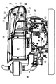
図8に例示するように、エンジン(42)はクランクケース(43)の後方にシリンダ部(44)が配置された横形エンジンで、燃料タンク(5)はクランクケース(43)の真上に配置され、ヘッドランプ(2)は燃料タンク(5)の前方に配置されているので、燃料タンク(5)とヘッドランプ(2)とがシリンダ部(44)やシリンダヘッド(46)の熱影響を受けにくく、ヘッドランプ(2)と燃料タンク(5)の過熱を抑制することができる。
(Invention of Claim 17)
In addition to the effect of the invention according to
<Effect> Overheating of the headlamp and the fuel tank can be suppressed.
As illustrated in FIG. 8, the engine (42) is a horizontal engine in which a cylinder portion (44) is disposed behind the crankcase (43), and the fuel tank (5) is disposed directly above the crankcase (43). Since the headlamp (2) is disposed in front of the fuel tank (5), the fuel tank (5) and the headlamp (2) affect the thermal effects of the cylinder portion (44) and the cylinder head (46). It is difficult to receive, and overheating of the headlamp (2) and the fuel tank (5) can be suppressed.
(請求項18に係る発明)
請求項17に係る発明の効果に加え、次の効果を奏する。
《効果》 機械へのエンジンの搭載が容易になる。
図8に例示するように、エンジン(42)は、シリンダ部(44)の真上にエンジン冷却水のラジエータ(45)を取り付けた水冷エンジンであるため、ヘッドランプ(2)と燃料タンク(5)とラジエータ(45)とをエンジン(42)と一体で、農業機械や建設機械に搭載することができ、各種機械へのエンジン(42)の搭載が容易になる。
(Invention of Claim 18)
In addition to the effect of the invention according to claim 17, the following effect is achieved.
<Effect> The engine can be easily mounted on the machine.
As illustrated in FIG. 8, the engine (42) is a water-cooled engine in which a radiator (45) for engine cooling water is mounted directly above the cylinder portion (44). Therefore, the headlamp (2) and the fuel tank (5 ) And the radiator (45) are integrated with the engine (42) and can be mounted on an agricultural machine or a construction machine, and the engine (42) can be easily mounted on various machines.
(請求項19に係る発明)
請求項17に係る発明の効果に加え、次の効果を奏する。
《効果》 機械へのエンジンの搭載が容易になる。
図8に例示するように、エンジン(42)は、シリンダ部(44)の真上にエンジン冷却水のホッパー(59)を取り付けた水冷エンジンであるため、ヘッドランプ(2)と燃料タンク(5)とホッパー(59)とをエンジン(42)と一体で、農業機械や建設機械に搭載することができ、各種機械へのエンジン(42)の搭載が容易になる。
(Invention of Claim 19)
In addition to the effect of the invention according to claim 17, the following effect is achieved.
<Effect> The engine can be easily mounted on the machine.
As illustrated in FIG. 8, the engine (42) is a water-cooled engine in which a hopper (59) for engine cooling water is mounted directly above the cylinder portion (44), and therefore, the headlamp (2) and the fuel tank (5 ) And the hopper (59) are integrated with the engine (42) and can be mounted on an agricultural machine or a construction machine, and the engine (42) can be easily mounted on various machines.
本発明の実施の形態を図面に基づいて説明する。図1から図10は本発明の実施形態に係るエンジンを説明する図で、この実施形態では、単気筒の水冷横形ディーゼルエンジンについて説明する。 Embodiments of the present invention will be described with reference to the drawings. FIGS. 1 to 10 are diagrams for explaining an engine according to an embodiment of the present invention. In this embodiment, a single-cylinder water-cooled horizontal diesel engine will be described.
このエンジンは、ヘッドランプと燃料タンクの支持構造を備えている。
ヘッドランプと燃料タンクの支持構造の概要は、次の通りである。
図2(A)に示すように、ヘッドランプ支持体(1)にヘッドランプ(2)が取り付けられ、ヘッドランプ(2)はランプハウジング(3)の前部にレンズ(4)を取り付けて構成され、このヘッドランプ(2)の後方に燃料タンク(5)が配置され、この燃料タンク(5)から前方に取付フランジ(6)が突出され、この取付フランジ(6)がヘッドランプ支持体(1)に固定されている。
ランプハウジング(3)内には光源ランプ(48)が収容されている。ランプハウジング(3)の内面は反射面となっている。
This engine includes a support structure for a headlamp and a fuel tank.
The outline of the support structure of the headlamp and the fuel tank is as follows.
As shown in FIG. 2 (A), a headlamp (1) is attached to a headlamp support (1), and the headlamp (2) is constructed by attaching a lens (4) to the front of a lamp housing (3). A fuel tank (5) is disposed behind the headlamp (2), a mounting flange (6) is projected forward from the fuel tank (5), and the mounting flange (6) is a headlamp support ( It is fixed to 1).
A light source lamp (48) is accommodated in the lamp housing (3). The inner surface of the lamp housing (3) is a reflecting surface.
ヘッドランプと燃料タンクの支持構造の工夫は、次の通りである。
図1(A)、図2(A)(B)、図3に示すように、ランプハウジング(3)とレンズ(4)との接合部(7)のうち、ヘッドランプ天井壁(8)に形成された接合部天井壁部分(9)の全部が、燃料タンク(5)の取付フランジ(6)よりも高い位置に配置されている。図1(A)では、接合部天井壁部分(9)は太い実線及び太い破線で示されている。
雨水等がランプハウジング(3)とレンズ(4)との接合部(7)に進入するのを抑制する観点からは、接合部天井壁部分(9)の全部が、燃料タンク(5)の取付フランジ(6)よりも高い位置に配置されていることが望ましいが、接合部天井壁部分(9)の一部が、燃料タンク(5)の取付フランジ(6)よりも高い位置に配置されているものであってもよい。
The device for supporting the headlamp and the fuel tank is as follows.
As shown in FIGS. 1 (A), 2 (A), 2 (B) and 3, the headlamp ceiling wall (8) of the joint (7) between the lamp housing (3) and the lens (4) is provided. All of the formed joint ceiling wall portions (9) are arranged at a position higher than the mounting flange (6) of the fuel tank (5). In FIG. 1 (A), the joint ceiling wall portion (9) is indicated by a thick solid line and a thick broken line.
From the viewpoint of preventing rainwater and the like from entering the joint (7) between the lamp housing (3) and the lens (4), the entire joint ceiling wall (9) is attached to the fuel tank (5). Although it is desirable to be disposed at a position higher than the flange (6), a part of the joint ceiling wall portion (9) is disposed at a position higher than the mounting flange (6) of the fuel tank (5). It may be.
燃料タンクの取り付け構造は、次の通りである。
図1(A)に示すように、ヘッドランプ支持体(1)が枠体(10)を備え、枠体(10)が横向きの上枠部(11)と立向きの左右の横側枠部(12)(12)とを備え、図1(A)、図2(A)(B)、図3に示すように、上枠部(11)にタンク固定手段(13)で、燃料タンク(5)の取付フランジ(6)が固定されている。
タンク固定手段(13)はボルトである。取付フランジ(6)は、燃料タンク(5)の前周壁(49)から前向きに突出している。燃料タンク(5)の天井壁(47)には給油口(57)がある。
The fuel tank mounting structure is as follows.
As shown in FIG. 1 (A), the headlamp support (1) is provided with a frame (10), and the frame (10) is a horizontal upper frame (11) and left and right horizontal frames. (12) and (12), and as shown in FIGS. 1 (A), 2 (A), (B), and 3, the tank fixing means (13) is attached to the upper frame portion (11), and the fuel tank ( The mounting flange (6) of 5) is fixed.
The tank fixing means (13) is a bolt. The mounting flange (6) protrudes forward from the front peripheral wall (49) of the fuel tank (5). There is a fuel filler opening (57) in the ceiling wall (47) of the fuel tank (5).
ヘッドランプ支持体の構造は、次の通りである。
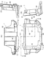
図7(A)〜(D)に示すように、ヘッドランプ支持体(1)は、水平な基部(50)と、この基部(50)の前端縁部から上向きに導出した枠体(10)とで構成されている。図1(A)に示すように、枠体(10)には、左右2対のヘッドランプ固定手段(51)(51)でヘッドランプ(2)が固定される。
The structure of the headlamp support is as follows.
As shown in FIGS. 7A to 7D, the headlamp support (1) includes a horizontal base (50) and a frame (10) led upward from the front edge of the base (50). It consists of and. As shown in FIG. 1 (A), the headlamp (2) is fixed to the frame (10) by two pairs of left and right headlamp fixing means (51) (51).
ヘッドランプの接合部と枠体との関係は、次の通りである。
図1(A)に示すように、ランプハウジング(3)とレンズ(4)との接合部(7)のうち、左右のヘッドランプ横側壁(14)(14)に形成された左右の接合部横側壁部分(15)(15)の全部が、正面前方から見て、ヘッドランプ支持体(1)の左右の横側枠部(12)(12)よりも外寄りに配置されている。図1(A)では、接合部横側壁部分(15)は太い実線で示されている。
雨水等がランプハウジング(3)とレンズ(4)との接合部(7)に進入するのを抑制する観点からは、接合部横側壁部分(15)(15)の全部が、正面前方から見て、ヘッドランプ支持体(1)の左右の横側枠部(12)(12)よりも外寄りに配置されているのが望ましいが、接合部横側壁部分(15)(15)の少なくとも上半部が、正面前方から見て、ヘッドランプ支持体(1)の左右の横側枠部(12)(12)よりも外寄りに配置されているものであればよい。
The relationship between the joint portion of the headlamp and the frame is as follows.
As shown in FIG. 1 (A), left and right joints formed on the left and right headlamp lateral walls (14) and (14) of the joint (7) between the lamp housing (3) and the lens (4). All of the lateral side wall portions (15) and (15) are arranged on the outer side of the left and right lateral frame portions (12) and (12) of the headlamp support (1) when viewed from the front front. In FIG. 1 (A), the joint side wall portion (15) is shown by a thick solid line.
From the viewpoint of preventing rainwater and the like from entering the joint (7) between the lamp housing (3) and the lens (4), all of the joint lateral wall portions (15) and (15) are viewed from the front front. The headlamp support (1) is preferably disposed on the outer side of the left and right lateral frame portions (12) and (12), but at least above the joint lateral wall portions (15) and (15). What is necessary is just to arrange | position a half part outside the left-right side frame part (12) (12) of the right and left of a headlamp support body (1) seeing from the front front.
図2(A)に示すように、ランプハウジング(3)とレンズ(4)との接合部(7)のうち、左右のヘッドランプ横側壁(14)(14)に形成された左右の接合部横側壁部分(15)(15)の下半部が、ヘッドランプ支持体(1)の左右の横側枠部(12)(12)よりも前寄りに配置されている。
雨水等がランプハウジング(3)とレンズ(4)との接合部(7)に進入するのを抑制する観点からは、左右の接合部横側壁部分(15)(15)の全部が、ヘッドランプ支持体(1)の左右の横側枠部(12)(12)よりも前寄りに配置されているのが望ましいが、左右のヘッドランプ横側壁(14)(14)に形成された左右の接合部横側壁部分(15)(15)の少なくとも下半部が、ヘッドランプ支持体(1)の左右の横側枠部(12)(12)よりも前寄りに配置されているものであればよい。
As shown in FIG. 2 (A), left and right joints formed on the left and right headlamp lateral walls (14) and (14) of the joint (7) between the lamp housing (3) and the lens (4). The lower half of the lateral side wall portions (15) (15) is disposed in front of the left and right lateral frame portions (12) (12) of the headlamp support (1).
From the viewpoint of suppressing rainwater and the like from entering the joint (7) between the lamp housing (3) and the lens (4), the left and right joint lateral wall portions (15) and (15) are all made of the headlamp. The left and right lateral frame portions (12) and (12) of the support (1) are preferably disposed in front of the left and right headlamp lateral walls (14) and (14). At least the lower half of the joint side wall portions (15) and (15) is arranged in front of the left and right lateral frame portions (12) and (12) of the headlamp support (1). That's fine.
図2(A)、図3に示すように、接合部天井壁部分(9)が上枠部(11)の真上に配置され、ランプハウジング(3)がヘッドランプ支持体(1)の枠内を貫通している。
図2(A)に示すように、ヘッドランプ支持体(1)の左右の横側枠部(12)(12)は後に向かって下り傾斜し、ランプハウジング(3)とレンズ(4)との接合部(7)のうち、左右のヘッドランプ横側壁(14)に形成された左右の接合部横側壁部分(15)(15)は前に向かって下り傾斜している。
As shown in FIGS. 2 (A) and 3, the joint ceiling wall portion (9) is disposed immediately above the upper frame portion (11), and the lamp housing (3) is the frame of the headlamp support (1). It penetrates inside.
As shown in FIG. 2 (A), the left and right lateral frame portions (12) and (12) of the headlamp support (1) are inclined downward toward the rear, so that the lamp housing (3) and the lens (4) Of the joint portion (7), the left and right joint portion lateral wall portions (15) and (15) formed on the left and right headlamp lateral sidewalls (14) are inclined downward toward the front.
ヘッドランプの構成は、次の通りである。
図2(B)に示すように、接合部天井壁部分(9)がランプハウジング(3)とレンズ(4)との嵌合部(16)で構成され、この嵌合部(16)の嵌合隙間(17)の外側入口(18)が嵌合隙間(17)の前部に形成されている。
図2(B)に示すように、嵌合部(16)がランプハウジング(3)に形成された嵌合溝(20)とレンズ(4)に形成された嵌入部分(22)とからなり、嵌合溝(20)の溝入口(23)が嵌合溝(20)の前端で開口され、この溝入口(23)からレンズ(4)の嵌入部分(22)が後向きに嵌入されている。
嵌合隙間(17)はシール材(53)で封止されている。
図2(C)に示すように、接合部底壁部分(38)も接合部天井壁部分(9)と同様の構造が採用されている。図1(B)(C)に示すように、接合部横側壁部分(15)と接合部底壁部分(38)も接合部天井壁部分(9)と同様の構造が採用されている。図1(A)(C)、図4(A)(B)、図5(A)(B)、図6(A)(B)に示すように、レンズ(4)は係止部(54)でランプハウジング(3)に係止されている。
The configuration of the headlamp is as follows.
As shown in FIG. 2B, the joint ceiling wall portion (9) is composed of a fitting portion (16) between the lamp housing (3) and the lens (4), and the fitting portion (16) is fitted. An outer inlet (18) of the joint gap (17) is formed at the front part of the fitting gap (17).
As shown in FIG. 2 (B), the fitting portion (16) comprises a fitting groove (20) formed in the lamp housing (3) and a fitting portion (22) formed in the lens (4). The groove inlet (23) of the fitting groove (20) is opened at the front end of the fitting groove (20), and the fitting portion (22) of the lens (4) is fitted backward from the groove inlet (23).
The fitting gap (17) is sealed with a sealing material (53).
As shown in FIG. 2C, the joint bottom wall portion (38) has the same structure as the joint ceiling wall portion (9). As shown in FIGS. 1B and 1C, the joint side wall portion (15) and the joint bottom wall portion (38) have the same structure as the joint ceiling wall portion (9). As shown in FIGS. 1 (A) (C), 4 (A) (B), 5 (A) (B), and 6 (A) (B), the lens (4) has a locking portion (54). ) To the lamp housing (3).
図2(B)に示すように、接合部天井壁部分(9)の接合隙間(24)の外側入口(25)の後方で、ヘッドランプ天井壁(8)から上向きに立壁(26)が設けられ、図4(A)(B)、図5(A)、図6(A)(B)に示すように、この立壁(26)がヘッドランプ天井壁(8)に沿って横方向に連続形成されている。
図4(A)(B)、図5(A)、図6(A)(B)に示すように、ヘッドランプ天井壁(8)の左右の横寄り部分(27)(27)がその中央部分(28)よりも高い位置まで隆起し、接合部天井壁部分(9)の左右の横寄り部分(29)(29)がその中央部分(30)よりも高く配置され、隆起したヘッドランプ天井壁(8)の左右の横寄り部分(27)(27)の間に立壁(26)が配置されている。
図4(A)(B)、図5(A)、図6(A)(B)に示すように、ヘッドランプ天井壁(8)の左右の横寄り部分(27)(27)に立壁(26)の左右両側が連結されている。
As shown in FIG. 2B, a standing wall (26) is provided upward from the headlamp ceiling wall (8) behind the outer entrance (25) of the joint gap (24) of the joint ceiling wall portion (9). 4 (A) (B), 5 (A), 6 (A) and 6 (B), the upright wall (26) continues laterally along the headlamp ceiling wall (8). Is formed.
4A, 4B, 5A, 6A, and 6B, the left and right
4 (A) (B), 5 (A), 6 (A) and 6 (B), standing walls (27, 27) on the left and right lateral portions (27), (27) of the headlamp ceiling wall (8) The left and right sides of 26) are connected.
ヘッドランプと上下カバーとの関係は、次の通りである。
図2(A)(B)に示すように、立壁(26)に上カバー固定手段(31)で上カバー(32)が固定され、この上カバー(32)で接合部天井壁部分(9)と上カバー固定手段(31)とがその前方と上方から覆われ、図2(A)(B)、図5(B)に示すように、上カバー(32)の下縁(33)がヘッドランプ天井壁(8)に沿っている。
図2(A)(B)、図3に示すように、上カバー(32)の後縁(34)が燃料タンク(5)の前面(35)に沿っている。
図2(A)(C)に示すように、ヘッドランプ(2)に下カバー固定手段(36)で下カバー(37)が固定され、ランプハウジング(3)とレンズ(4)との接合部(7)のうち、ヘッドランプ底壁(40)に形成された接合部底壁部分(38)と下カバー固定手段(36)とがその前方と下方から下カバー(37)で覆われ、図2(A)(C)、図5(B)に示すように、下カバー(37)の上縁(39)がヘッドランプ底壁(40)に沿っている。
図2(A)に示すように、レンズ(4)の前壁(41)の下半部が前方に突出する凸状湾曲面とされている。
図1(B)(C)、図3に示すように、上カバー(32)の下縁(33)と下カバー(37)の上縁(39)は、係止部(55)でヘッドランプ(2)に係止されている。
The relationship between the headlamp and the upper and lower covers is as follows.
As shown in FIGS. 2 (A) and 2 (B), the upper cover (32) is fixed to the standing wall (26) by the upper cover fixing means (31), and the joint ceiling wall portion (9) is fixed by the upper cover (32). And the upper cover fixing means (31) are covered from the front and upper side, and as shown in FIGS. 2 (A), (B), and (B), the lower edge (33) of the upper cover (32) is the head. Along the lamp ceiling wall (8).
As shown in FIGS. 2 (A), 2 (B) and 3, the rear edge (34) of the upper cover (32) extends along the front surface (35) of the fuel tank (5).
As shown in FIGS. 2 (A) and 2 (C), the lower cover (37) is fixed to the headlamp (2) by the lower cover fixing means (36), and the joint between the lamp housing (3) and the lens (4). (7), the joint bottom wall portion (38) formed on the headlamp bottom wall (40) and the lower cover fixing means (36) are covered with the lower cover (37) from the front and the lower side thereof. 2 (A) (C) and FIG. 5 (B), the upper edge (39) of the lower cover (37) is along the head lamp bottom wall (40).
As shown in FIG. 2A, the lower half of the front wall (41) of the lens (4) is a convex curved surface protruding forward.
As shown in FIGS. 1B, 1C and 3, the
図2(A)に示すように、ヘッドランプ(2)と燃料タンク(5)とがヘッドランプ支持体(1)を介してエンジン(42)に支持されている。
図2(A)に示すように、ヘッドランプ支持体(1)の基部(50)がエンジン(42)のクランクケース(43)に固定されている。
図8に示すように、エンジン(42)はクランクケース(43)の後方にシリンダ部(44)が配置された横形エンジンで、燃料タンク(5)はクランクケース(43)の真上に配置され、ヘッドランプ(2)は燃料タンク(5)の前方に配置されている。
図8に示すように、エンジン(42)は、シリンダ部(44)の真上にエンジン冷却水のラジエータ(45)を取り付けた水冷エンジンである。
図8、図9に示すように、燃料タンク(5)の左右両側には、サイドカバー(56)(56)が配置され、このサイドカバー(56)(56)はヘッドランプ支持体(1)の横側枠部(12)とラジエータ(45)にサイドカバー固定手段(58)で固定されている。
As shown in FIG. 2 (A), the headlamp (2) and the fuel tank (5) are supported by the engine (42) via the headlamp support (1).
As shown in FIG. 2A, the base (50) of the headlamp support (1) is fixed to the crankcase (43) of the engine (42).
As shown in FIG. 8, the engine (42) is a horizontal engine in which a cylinder part (44) is arranged behind the crankcase (43), and the fuel tank (5) is arranged directly above the crankcase (43). The headlamp (2) is disposed in front of the fuel tank (5).
As shown in FIG. 8, the engine (42) is a water-cooled engine in which a radiator (45) for engine cooling water is mounted directly above the cylinder portion (44).
As shown in FIGS. 8 and 9, side covers (56) and (56) are arranged on the left and right sides of the fuel tank (5), and the side covers (56) and (56) are the headlamp support (1). Are fixed to the lateral frame portion (12) and the radiator (45) by side cover fixing means (58).
図10は、本発明の実施形態の変更例で、エンジン冷却水のラジエータ(45)に代えて、エンジン冷却水のホッパー(59)を用いている。すなわち、このエンジン(42)は、シリンダ部(44)の真上にエンジン冷却水のホッパー(59)を取り付けた水冷エンジンである。ホッパー(59)はエンジン冷却水を溜めておくタンクで、ホッパー(59)内のエンジン冷却水はシリンダ部(44)の熱を吸収して気化する。他の構造と機能は図8のエンジンと同じであり、図10中、図8のエンジンと同一の要素には同一の符号を付しておく。 FIG. 10 shows a modification of the embodiment of the present invention, in which an engine coolant hopper (59) is used instead of the engine coolant radiator (45). That is, the engine (42) is a water-cooled engine in which an engine cooling water hopper (59) is mounted directly above the cylinder portion (44). The hopper (59) is a tank for storing engine cooling water, and the engine cooling water in the hopper (59) absorbs heat of the cylinder part (44) and vaporizes. Other structures and functions are the same as those of the engine shown in FIG. 8, and in FIG. 10, the same elements as those of the engine shown in FIG.
(1) ヘッドランプ支持体
(2) ヘッドランプ
(3) ランプハウジング
(4) レンズ
(5) 燃料タンク
(6) 取付フランジ
(7) 接合部
(8) ヘッドランプ天井壁
(9) 接合部天井壁部分
(10) 枠体
(11) 上枠部
(12) 横側枠部
(13) タンク固定手段
(14) ヘッドランプ横側壁
(15) 接合部横側壁部分
(16) 嵌合部
(17) 嵌合隙間
(18) 外側入口
(20) 嵌合溝
(22) 嵌入部分
(23) 溝入口
(24) 接合隙間
(25) 外側入口
(26) 立壁
(27) ヘッドランプ天井壁の横寄り部分
(28) ヘッドランプ天井壁の中央部分
(29) 接合部天井壁部分の横寄り部分
(30) 接合部天井壁部分の中央部分
(31) 上カバー固定手段
(32) 上カバー
(33) 下縁
(34) 後縁
(35) 前面
(36) 下カバー固定手段
(37) 下カバー
(38) 接合部底壁部分
(39) 上縁
(40) ヘッドランプ底壁
(41) レンズの前壁
(42) エンジン
(43) クランクケース
(44) シリンダ部
(45) ラジエータ
(59) ホッパー
(1) Headlamp support
(2) Headlamp
(3) Lamp housing
(4) Lens
(5) Fuel tank
(6) Mounting flange
(7) Joint
(8) Headlamp ceiling wall
(9) Joint ceiling wall
(10) Frame
(11) Upper frame
(12) Horizontal frame
(13) Tank fixing means
(14) Headlamp side wall
(15) Joint side wall
(16) Fitting part
(17) Mating gap
(18) Outside entrance
(20) Mating groove
(22) Insertion part
(23) Groove entrance
(24) Joining gap
(25) Outside entrance
(26) Standing wall
(27) Headlamp side wall
(28) Central part of headlamp ceiling wall
(29) Lateral part of the ceiling wall of the joint
(30) Central part of the ceiling wall of the joint
(31) Upper cover fixing means
(32) Upper cover
(33) Lower edge
(34) Trailing edge
(35) Front
(36) Lower cover fixing means
(37) Lower cover
(38) Joint bottom wall
(39) Upper edge
(40) Headlamp bottom wall
(41) Front wall of lens
(42) Engine
(43) Crankcase
(44) Cylinder part
(45) Radiator
(59) Hopper
Claims (19)
ランプハウジング(3)とレンズ(4)との接合部(7)のうち、ヘッドランプ天井壁(8)に形成された接合部天井壁部分(9)の少なくとも一部が、燃料タンク(5)の取付フランジ(6)よりも高い位置に配置されている、ことを特徴とするヘッドランプと燃料タンクの支持構造。 A headlamp (1) is attached to a headlamp support (1), and the headlamp (2) is constructed by attaching a lens (4) to the front of a lamp housing (3), and the rear of the headlamp (2). A fuel tank (5) is disposed on the headlamp, and a mounting flange (6) projects forward from the fuel tank (5), and the mounting flange (6) is fixed to the headlamp support (1). A fuel tank support structure,
Of the joint portion (7) between the lamp housing (3) and the lens (4), at least part of the joint portion ceiling wall portion (9) formed on the headlamp ceiling wall (8) is a fuel tank (5). A support structure for a headlamp and a fuel tank, which is disposed at a position higher than the mounting flange (6).
ヘッドランプ支持体(1)が枠体(10)を備え、枠体(10)が横向きの上枠部(11)と立向きの左右の横側枠部(12)(12)とを備え、
上枠部(11)にタンク固定手段(13)で、燃料タンク(5)の取付フランジ(6)が固定されている、ことを特徴とするヘッドランプと燃料タンクの支持構造。 The headlamp and fuel tank support structure according to claim 1,
The headlamp support (1) includes a frame (10), and the frame (10) includes a horizontal upper frame (11) and vertical horizontal frames (12) and (12).
A support structure for a headlamp and a fuel tank, wherein a mounting flange (6) of the fuel tank (5) is fixed to the upper frame portion (11) by tank fixing means (13).
ランプハウジング(3)とレンズ(4)との接合部(7)のうち、左右のヘッドランプ横側壁(14)(14)に形成された左右の接合部横側壁部分(15)(15)の少なくとも上半部が、正面前方から見て、ヘッドランプ支持体(1)の左右の横側枠部(12)(12)よりも外寄りに配置されている、ことを特徴とするヘッドランプと燃料タンクの支持構造。 The headlamp and fuel tank support structure according to claim 2,
Of the joint portion (7) between the lamp housing (3) and the lens (4), the left and right joint side wall portions (15), (15) formed on the left and right headlamp side walls (14), (14). A headlamp characterized in that at least an upper half portion is disposed outside the left and right lateral frame portions (12) and (12) of the headlamp support (1) when viewed from the front front side; Fuel tank support structure.
ランプハウジング(3)とレンズ(4)との接合部(7)のうち、左右のヘッドランプ横側壁(14)(14)に形成された左右の接合部横側壁部分(15)(15)の少なくとも下半部が、ヘッドランプ支持体(1)の左右の横側枠部(12)(12)よりも前寄りに配置されている、ことを特徴とするヘッドランプと燃料タンクの支持構造。 In the headlamp and fuel tank support structure according to claim 2 or 3,
Of the joint portion (7) between the lamp housing (3) and the lens (4), the left and right joint side wall portions (15), (15) formed on the left and right headlamp side walls (14), (14). A support structure for a headlamp and a fuel tank, characterized in that at least a lower half portion is disposed in front of the left and right lateral frame portions (12) and (12) of the headlamp support (1).
接合部天井壁部分(9)が上枠部(11)の真上に配置され、ランプハウジング(3)がヘッドランプ支持体(1)の枠内を貫通している、ことを特徴とするヘッドランプと燃料タンクの支持構造。 In the headlamp and fuel tank support structure according to any one of claims 2 to 4,
A head characterized in that the joint ceiling wall portion (9) is disposed immediately above the upper frame portion (11), and the lamp housing (3) penetrates the frame of the headlamp support (1). Support structure for lamp and fuel tank.
ヘッドランプ支持体(1)の左右の横側枠部(12)(12)は後に向かって下り傾斜し、ランプハウジング(3)とレンズ(4)との接合部(7)のうち、左右のヘッドランプ横側壁(14)に形成された左右の接合部横側壁部分(15)(15)は前に向かって下り傾斜している、ことを特徴とするヘッドランプと燃料タンクの支持構造。 In the headlamp and fuel tank support structure according to claim 5,
The left and right lateral frame portions (12), (12) of the headlamp support (1) are inclined downward and the right and left of the joint portion (7) between the lamp housing (3) and the lens (4). A support structure for a headlamp and a fuel tank, characterized in that left and right joint lateral wall portions (15) and (15) formed on the lateral wall of the headlamp (14) are inclined downward toward the front.
接合部天井壁部分(9)がランプハウジング(3)とレンズ(4)との嵌合部(16)で構成され、この嵌合部(16)の嵌合隙間(17)の外側入口(18)が嵌合隙間(17)の前部に形成されている、ことを特徴とするヘッドランプと燃料タンクの支持構造。 In the headlamp and fuel tank support structure according to any one of claims 1 to 6,
The joint ceiling wall portion (9) is composed of a fitting portion (16) between the lamp housing (3) and the lens (4), and the outer entrance (18) of the fitting gap (17) of the fitting portion (16). ) Is formed in the front part of the fitting gap (17), and the support structure for the headlamp and the fuel tank.
嵌合部(16)がランプハウジング(3)に形成された嵌合溝(20)とレンズ(4)に形成された嵌入部分(22)とからなり、嵌合溝(20)の溝入口(23)が嵌合溝(20)の前端で開口され、この溝入口(23)からレンズ(4)の嵌入部分(22)が後向きに嵌入されている、ことを特徴とするヘッドランプと燃料タンクの支持構造。 The headlamp and fuel tank support structure according to claim 7,
The fitting portion (16) includes a fitting groove (20) formed in the lamp housing (3) and a fitting portion (22) formed in the lens (4). 23) is opened at the front end of the fitting groove (20), and the fitting portion (22) of the lens (4) is fitted backward from the groove inlet (23), and the headlamp and the fuel tank Support structure.
接合部天井壁部分(9)の接合隙間(24)の外側入口(25)の後方で、ヘッドランプ天井壁(8)から上向きに立壁(26)が設けられ、
この立壁(26)がヘッドランプ天井壁(8)に沿って横方向に連続形成されている、ことを特徴とするヘッドランプと燃料タンクの支持構造。 In the headlamp and fuel tank support structure according to any one of claims 1 to 8,
A standing wall (26) is provided upward from the headlamp ceiling wall (8) behind the outer entrance (25) of the joint gap (24) of the joint ceiling wall portion (9),
A structure for supporting a headlamp and a fuel tank, wherein the standing wall (26) is continuously formed in a lateral direction along the headlamp ceiling wall (8).
ヘッドランプ天井壁(8)の左右の横寄り部分(27)(27)がその中央部分(28)よりも高い位置まで隆起し、接合部天井壁部分(9)の左右の横寄り部分(29)(29)がその中央部分(30)よりも高く配置され、隆起したヘッドランプ天井壁(8)の左右の横寄り部分(27)(27)の間に立壁(26)が配置されている、ことを特徴とするヘッドランプと燃料タンクの支持構造。 The headlamp and fuel tank support structure according to claim 9,
The left and right lateral portions (27), (27) of the headlamp ceiling wall (8) are raised to a position higher than the central portion (28), and the laterally lateral portions (29, 29) of the joint ceiling wall portion (9) are raised. ) (29) is disposed higher than the central portion (30), and the standing wall (26) is disposed between the left and right lateral portions (27) and (27) of the raised headlamp ceiling wall (8). , Characterized in that the support structure of the headlamp and the fuel tank.
ヘッドランプ天井壁(8)の左右の横寄り部分(27)(27)に立壁(26)の左右両側が連結されている、ことを特徴とするヘッドランプと燃料タンクの支持構造。 The support structure for a headlamp and a fuel tank according to claim 10,
A support structure for a headlamp and a fuel tank, characterized in that the left and right sides of the upright wall (26) are connected to the left and right lateral portions (27) and (27) of the headlamp ceiling wall (8).
立壁(26)に上カバー固定手段(31)で上カバー(32)が固定され、この上カバー(32)で接合部天井壁部分(9)と上カバー固定手段(31)とがその前方と上方から覆われ、
上カバー(32)の下縁(33)がヘッドランプ天井壁(8)に沿っている、ことを特徴とするヘッドランプと燃料タンクの支持構造。 The headlamp and fuel tank support structure according to any one of claims 9 to 11,
The upper cover (32) is fixed to the standing wall (26) by the upper cover fixing means (31), and the joint cover ceiling wall portion (9) and the upper cover fixing means (31) are moved forward of the upper cover (32). Covered from above,
A support structure for a headlamp and a fuel tank, wherein the lower edge (33) of the upper cover (32) is along the headlamp ceiling wall (8).
上カバー(32)の後縁(34)が燃料タンク(5)の前面(35)に沿っている、ことを特徴とするヘッドランプと燃料タンクの支持構造。 In the headlamp and fuel tank support structure according to claim 12,
A support structure for a headlamp and a fuel tank, wherein a rear edge (34) of the upper cover (32) is along a front surface (35) of the fuel tank (5).
ヘッドランプ(2)に下カバー固定手段(36)で下カバー(37)が固定され、ランプハウジング(3)とレンズ(4)との接合部(7)のうち、ヘッドランプ底壁(40)に形成された接合部底壁部分(38)と下カバー固定手段(36)とがその前方と下方から下カバー(37)で覆われ、
下カバー(37)の上縁(39)がヘッドランプ底壁(40)に沿っている、ことを特徴とするヘッドランプと燃料タンクの支持構造。 In the headlamp and fuel tank support structure according to any one of claims 1 to 13,
The lower cover (37) is fixed to the headlamp (2) by the lower cover fixing means (36), and the headlamp bottom wall (40) in the joint (7) between the lamp housing (3) and the lens (4). The joint bottom wall portion (38) and the lower cover fixing means (36) formed on the lower cover (37) are covered with the lower cover (37) from the front and lower sides,
A support structure for a headlamp and a fuel tank, wherein an upper edge (39) of the lower cover (37) is along the headlamp bottom wall (40).
レンズ(4)の前壁(41)の下半部が前方に突出する凸状湾曲面とされている、ことを特徴とするヘッドランプと燃料タンクの支持構造。 The support structure for a headlamp and a fuel tank according to claim 14,
A support structure for a headlamp and a fuel tank, wherein the lower half of the front wall (41) of the lens (4) has a convex curved surface protruding forward.
ヘッドランプ(2)と燃料タンク(5)とがヘッドランプ支持体(1)を介してエンジン(42)に支持されている、ことを特徴とするヘッドランプと燃料タンクの支持構造。 The headlamp and fuel tank support structure according to any one of claims 1 to 15,
A headlamp and fuel tank support structure, wherein the headlamp (2) and the fuel tank (5) are supported by the engine (42) via a headlamp support (1).
エンジン(42)はクランクケース(43)の後方にシリンダ部(44)が配置された横形エンジンで、燃料タンク(5)はクランクケース(43)の真上に配置され、ヘッドランプ(2)は燃料タンク(5)の前方に配置されている、ことを特徴とするヘッドランプと燃料タンクの支持構造。 The support structure for a headlamp and a fuel tank according to claim 16,
The engine (42) is a horizontal engine in which a cylinder part (44) is arranged behind the crankcase (43), the fuel tank (5) is arranged directly above the crankcase (43), and the headlamp (2) is A support structure for a headlamp and a fuel tank, which is disposed in front of the fuel tank (5).
エンジン(42)は、シリンダ部(44)の真上にエンジン冷却水のラジエータ(45)を取り付けた水冷エンジンである、ことを特徴とするヘッドランプと燃料タンクの支持構造。 The support structure for a headlamp and a fuel tank according to claim 17,
The engine (42) is a water-cooled engine in which a radiator (45) for engine cooling water is mounted directly above a cylinder portion (44), and the support structure for a headlamp and a fuel tank.
エンジン(42)は、シリンダ部(44)の真上にエンジン冷却水のホッパー(59)を取り付けた水冷エンジンである、ことを特徴とするヘッドランプと燃料タンクの支持構造。 The support structure for a headlamp and a fuel tank according to claim 17,
The engine (42) is a water-cooled engine in which a hopper (59) for engine cooling water is mounted directly above the cylinder part (44), and the support structure for the headlamp and the fuel tank.
Priority Applications (3)
| Application Number | Priority Date | Filing Date | Title |
|---|---|---|---|
| JP2008217500A JP5049923B2 (en) | 2008-08-27 | 2008-08-27 | Support structure for headlamp and fuel tank |
| CN200910170462.7A CN101659231B (en) | 2008-08-27 | 2009-08-26 | Structure for supporting head light and fuel tank |
| CN201410140736.9A CN103921714B (en) | 2008-08-27 | 2009-08-26 | Headlamp and the supporting construction of fuel tank |
Applications Claiming Priority (1)
| Application Number | Priority Date | Filing Date | Title |
|---|---|---|---|
| JP2008217500A JP5049923B2 (en) | 2008-08-27 | 2008-08-27 | Support structure for headlamp and fuel tank |
Related Child Applications (1)
| Application Number | Title | Priority Date | Filing Date |
|---|---|---|---|
| JP2012161581A Division JP5470425B2 (en) | 2012-07-20 | 2012-07-20 | Support structure for headlamp and fuel tank |
Publications (2)
| Publication Number | Publication Date |
|---|---|
| JP2010055851A true JP2010055851A (en) | 2010-03-11 |
| JP5049923B2 JP5049923B2 (en) | 2012-10-17 |
Family
ID=41787545
Family Applications (1)
| Application Number | Title | Priority Date | Filing Date |
|---|---|---|---|
| JP2008217500A Active JP5049923B2 (en) | 2008-08-27 | 2008-08-27 | Support structure for headlamp and fuel tank |
Country Status (2)
| Country | Link |
|---|---|
| JP (1) | JP5049923B2 (en) |
| CN (2) | CN101659231B (en) |
Cited By (5)
| Publication number | Priority date | Publication date | Assignee | Title |
|---|---|---|---|---|
| JP2013047034A (en) * | 2011-08-29 | 2013-03-07 | Kubota Corp | Support structure of headlamp cover |
| WO2018168253A1 (en) * | 2017-03-17 | 2018-09-20 | ヤンマー株式会社 | Engine |
| WO2018168254A1 (en) * | 2017-03-17 | 2018-09-20 | ヤンマー株式会社 | Engine |
| JP2022113902A (en) * | 2017-08-29 | 2022-08-04 | ヤンマーパワーテクノロジー株式会社 | engine |
| JP7174100B2 (en) | 2020-11-18 | 2022-11-17 | アプライド マテリアルズ インコーポレイテッド | Methods for cleaning vacuum systems used to manufacture OLED devices, methods for vacuum deposition on substrates for manufacturing OLED devices, and vacuum over substrates for manufacturing OLED devices Apparatus for deposition |
Citations (5)
| Publication number | Priority date | Publication date | Assignee | Title |
|---|---|---|---|---|
| JPS591836U (en) * | 1982-06-28 | 1984-01-07 | 株式会社クボタ | Fuel tank support device on the crankcase of a horizontal engine |
| JPS59141129U (en) * | 1983-03-12 | 1984-09-20 | 株式会社クボタ | Horizontal engine with fuel tank mounted lamp |
| JPS6169476U (en) * | 1984-10-12 | 1986-05-12 | ||
| JP2002274253A (en) * | 2001-03-14 | 2002-09-25 | Honda Motor Co Ltd | Headlamp for motorcycle and fitting structure of headlamp for motorcycle |
| JP2008159429A (en) * | 2006-12-25 | 2008-07-10 | Honda Motor Co Ltd | Light |
Family Cites Families (2)
| Publication number | Priority date | Publication date | Assignee | Title |
|---|---|---|---|---|
| JP4853913B2 (en) * | 2006-09-29 | 2012-01-11 | 本田技研工業株式会社 | Motorcycle headlamp device |
| CN100572902C (en) * | 2007-04-26 | 2009-12-23 | 重庆宗申技术开发研究有限公司 | Headlamp |
-
2008
- 2008-08-27 JP JP2008217500A patent/JP5049923B2/en active Active
-
2009
- 2009-08-26 CN CN200910170462.7A patent/CN101659231B/en active Active
- 2009-08-26 CN CN201410140736.9A patent/CN103921714B/en active Active
Patent Citations (5)
| Publication number | Priority date | Publication date | Assignee | Title |
|---|---|---|---|---|
| JPS591836U (en) * | 1982-06-28 | 1984-01-07 | 株式会社クボタ | Fuel tank support device on the crankcase of a horizontal engine |
| JPS59141129U (en) * | 1983-03-12 | 1984-09-20 | 株式会社クボタ | Horizontal engine with fuel tank mounted lamp |
| JPS6169476U (en) * | 1984-10-12 | 1986-05-12 | ||
| JP2002274253A (en) * | 2001-03-14 | 2002-09-25 | Honda Motor Co Ltd | Headlamp for motorcycle and fitting structure of headlamp for motorcycle |
| JP2008159429A (en) * | 2006-12-25 | 2008-07-10 | Honda Motor Co Ltd | Light |
Cited By (7)
| Publication number | Priority date | Publication date | Assignee | Title |
|---|---|---|---|---|
| JP2013047034A (en) * | 2011-08-29 | 2013-03-07 | Kubota Corp | Support structure of headlamp cover |
| WO2018168253A1 (en) * | 2017-03-17 | 2018-09-20 | ヤンマー株式会社 | Engine |
| WO2018168254A1 (en) * | 2017-03-17 | 2018-09-20 | ヤンマー株式会社 | Engine |
| JP2018155180A (en) * | 2017-03-17 | 2018-10-04 | ヤンマー株式会社 | engine |
| JP2018155181A (en) * | 2017-03-17 | 2018-10-04 | ヤンマー株式会社 | engine |
| JP2022113902A (en) * | 2017-08-29 | 2022-08-04 | ヤンマーパワーテクノロジー株式会社 | engine |
| JP7174100B2 (en) | 2020-11-18 | 2022-11-17 | アプライド マテリアルズ インコーポレイテッド | Methods for cleaning vacuum systems used to manufacture OLED devices, methods for vacuum deposition on substrates for manufacturing OLED devices, and vacuum over substrates for manufacturing OLED devices Apparatus for deposition |
Also Published As
| Publication number | Publication date |
|---|---|
| JP5049923B2 (en) | 2012-10-17 |
| CN103921714A (en) | 2014-07-16 |
| CN101659231B (en) | 2014-05-14 |
| CN101659231A (en) | 2010-03-03 |
| CN103921714B (en) | 2016-08-17 |
Similar Documents
| Publication | Publication Date | Title |
|---|---|---|
| JP5049923B2 (en) | Support structure for headlamp and fuel tank | |
| EP2172389B1 (en) | Fender liner structure | |
| US7813639B2 (en) | Camera cover | |
| KR101789953B1 (en) | Two-wheeled motor vehicle | |
| US8632107B2 (en) | Rear structure of vehicle | |
| US8770330B2 (en) | Exterior shroud member for a saddle-type vehicle, and vehicle incorporating the same | |
| US9371104B2 (en) | Headlight device for motorcycle | |
| US8839896B2 (en) | Saddle type vehicle with regulator disposed below fuel tank | |
| US9676436B2 (en) | Headlight device for motorcycle | |
| JP2011111029A (en) | Front part lamp structure of saddle riding type vehicle | |
| US20160264199A1 (en) | Front structure of motorcycle | |
| JP2014061733A (en) | Vehicle lighting device structure | |
| JP4015257B2 (en) | Vehicle lamp | |
| US7073928B2 (en) | Vehicle headlight | |
| JP2007149583A (en) | Lamplight device | |
| JP5538787B2 (en) | Tail lamp unit | |
| JP5470425B2 (en) | Support structure for headlamp and fuel tank | |
| JP4297229B2 (en) | Motorcycle lighting equipment | |
| TWI363717B (en) | ||
| US9302724B2 (en) | Headlamp assembly for a saddle-type vehicle | |
| US20140293627A1 (en) | Headlight device for motorcycle | |
| JP5354356B2 (en) | Bumper holder | |
| JP7380353B2 (en) | front cowl | |
| JP2018095186A (en) | Tractor | |
| JP2014162285A (en) | Bicycle |
Legal Events
| Date | Code | Title | Description |
|---|---|---|---|
| A621 | Written request for application examination |
Free format text: JAPANESE INTERMEDIATE CODE: A621 Effective date: 20100927 |
|
| A977 | Report on retrieval |
Free format text: JAPANESE INTERMEDIATE CODE: A971007 Effective date: 20120215 |
|
| A131 | Notification of reasons for refusal |
Free format text: JAPANESE INTERMEDIATE CODE: A131 Effective date: 20120221 |
|
| A521 | Request for written amendment filed |
Free format text: JAPANESE INTERMEDIATE CODE: A523 Effective date: 20120518 |
|
| TRDD | Decision of grant or rejection written | ||
| A01 | Written decision to grant a patent or to grant a registration (utility model) |
Free format text: JAPANESE INTERMEDIATE CODE: A01 Effective date: 20120703 |
|
| A01 | Written decision to grant a patent or to grant a registration (utility model) |
Free format text: JAPANESE INTERMEDIATE CODE: A01 |
|
| A61 | First payment of annual fees (during grant procedure) |
Free format text: JAPANESE INTERMEDIATE CODE: A61 Effective date: 20120723 |
|
| FPAY | Renewal fee payment (event date is renewal date of database) |
Free format text: PAYMENT UNTIL: 20150727 Year of fee payment: 3 |
|
| R150 | Certificate of patent or registration of utility model |
Free format text: JAPANESE INTERMEDIATE CODE: R150 Ref document number: 5049923 Country of ref document: JP Free format text: JAPANESE INTERMEDIATE CODE: R150 |
|
| R250 | Receipt of annual fees |
Free format text: JAPANESE INTERMEDIATE CODE: R250 |
|
| R250 | Receipt of annual fees |
Free format text: JAPANESE INTERMEDIATE CODE: R250 |
|
| R250 | Receipt of annual fees |
Free format text: JAPANESE INTERMEDIATE CODE: R250 |
|
| R250 | Receipt of annual fees |
Free format text: JAPANESE INTERMEDIATE CODE: R250 |