JP2010055045A - Image forming toner, developer, toner containing receptacle, image forming apparatus, image forming method and process cartridge - Google Patents
Image forming toner, developer, toner containing receptacle, image forming apparatus, image forming method and process cartridge Download PDFInfo
- Publication number
- JP2010055045A JP2010055045A JP2008289916A JP2008289916A JP2010055045A JP 2010055045 A JP2010055045 A JP 2010055045A JP 2008289916 A JP2008289916 A JP 2008289916A JP 2008289916 A JP2008289916 A JP 2008289916A JP 2010055045 A JP2010055045 A JP 2010055045A
- Authority
- JP
- Japan
- Prior art keywords
- toner
- image forming
- wax
- image
- roller
- Prior art date
- Legal status (The legal status is an assumption and is not a legal conclusion. Google has not performed a legal analysis and makes no representation as to the accuracy of the status listed.)
- Granted
Links
Images


Landscapes
- Developing Agents For Electrophotography (AREA)
Abstract
Description
本発明は、複写機、静電印刷、プリンター、ファクシミリ、静電記録等の電子写真方式の画像形成に用いられるトナー、並びに該トナーを用いる現像剤、トナー入り容器、画像形成装置、画像形成方法及びプロセスカートリッジに関する。 The present invention relates to a toner used for image formation of an electrophotographic system such as a copying machine, electrostatic printing, printer, facsimile, electrostatic recording, and the like, a developer using the toner, a container containing the toner, an image forming apparatus, and an image forming method. And a process cartridge.
電子写真方式の画像形成装置は、電気的または磁気的に形成された潜像を、トナーによって顕像化する。例えば、感光体上に静電荷像(潜像)を形成し、次いで、該潜像をトナーにより現像して、トナー画像を形成している。トナー画像は、通常、紙等の被転写体(記録媒体)上に転写され、次いで、記録媒体上に定着される。トナー画像の記録媒体上への定着工程においては、そのエネルギー効率の良さから、加熱ローラ定着方式や加熱ベルト定着方式といった熱定着方式が広く用いられている。 An electrophotographic image forming apparatus visualizes an electrically or magnetically formed latent image with toner. For example, an electrostatic charge image (latent image) is formed on a photosensitive member, and then the latent image is developed with toner to form a toner image. The toner image is usually transferred onto a transfer medium (recording medium) such as paper and then fixed on the recording medium. In the fixing process of a toner image onto a recording medium, a heat fixing method such as a heating roller fixing method or a heating belt fixing method is widely used because of its energy efficiency.
近年、画像形成装置の高速化、省エネルギー化に対する市場からの要求は益々大きくなり、低温定着性に優れ、高品位な画像を提供できるトナーが求められている。しかしながら、トナーの低温定着性を達成するためには結着樹脂の軟化点を低くする必要がある。結着樹脂の軟化点が低いと、定着時にトナー像の一部が定着部材の表面に付着し、これがコピー用紙上に転移する、いわゆるオフセット(以下、ホットオフセットとも呼ぶ)が発生する。また、トナーの耐熱性が低下し、特に高温環境下においてトナー粒子同士が融着す
る、いわゆるブロッキングが発生する。その他に、現像器内においてもトナーが現像器内部やキャリアに融着して汚染する問題や、トナーが感光体表面にフィルミングしやすくなる問題があった。
In recent years, demands from the market for increasing the speed and energy saving of image forming apparatuses are increasing, and there is a demand for toners that are excellent in low-temperature fixability and can provide high-quality images. However, in order to achieve low-temperature fixability of the toner, it is necessary to lower the softening point of the binder resin. When the softening point of the binder resin is low, a part of the toner image adheres to the surface of the fixing member at the time of fixing, and a so-called offset (hereinafter also referred to as hot offset) occurs on the copy sheet. Further, the heat resistance of the toner is lowered, and so-called blocking occurs in which toner particles are fused with each other particularly in a high temperature environment. In addition, in the developing device, there are problems that the toner is fused and contaminated inside the developing device and the carrier, and that the toner is liable to film on the surface of the photoreceptor.
これらの課題を達成する技術として、特許文献1〜4がある。結着樹脂に環化ゴムを用い、ワックスを溶融させることで、トナーの低温軟化を達成しながら、優れた耐熱保存性と耐ホットオフセット性を得ることができる。しかしながら、環化ゴムは溶融時の接着性(タッキネス)が非常に高く、定着時において、トナーが定着部材に強く接着し、定着ローラまたは定着ベルトへの用紙詰まり(ジャム)が発生する問題があった。また、定着時にトナー中のワックスは環化ゴムと相溶するため、ワックスが画像表面に移動し難く、ワックスによる離型機能が作用しない問題があった。
As techniques for achieving these problems, there are
特許文献5には、バインダー樹脂に環化ゴムを用いると共に、着色剤の分散性を向上させる目的で、無機微粒子をトナー中に分散させたトナーの提案がなされている。これは、環化ゴムの接着性の良さを利用して、定着媒体への定着力にも優れるものであったが、必ずしも低温定着性や耐熱保存性に優れるものでは無かった。 Patent Document 5 proposes a toner in which cyclized rubber is used as a binder resin and inorganic fine particles are dispersed in the toner for the purpose of improving the dispersibility of the colorant. This was excellent in the fixing power to the fixing medium by utilizing the good adhesiveness of the cyclized rubber, but was not necessarily excellent in the low temperature fixing property and the heat resistant storage stability.
前述したように、環化ゴムを用いたトナーは、ワックスを相溶させることで、トナーの低温軟化が可能であるが、更に優れた低温定着性と、耐熱保存性、耐ホットオフセット性を成り立たせる為には、適正な環化ゴムと適正なワックスの組合せを行うことが重要である。しかしながら、これらの提案は、適正な特性を持つ環化ゴムとワックスの組合せについて規定したものではなく、低温定着性、耐熱保存性、耐ホットオフセット性、定着離型性を全て成り立たせるものではなかった。 As described above, the toner using the cyclized rubber can be softened at a low temperature by making the wax compatible with each other, but it has further excellent low-temperature fixability, heat-resistant storage stability, and hot-offset resistance. In order to achieve this, it is important to combine an appropriate cyclized rubber and an appropriate wax. However, these proposals do not stipulate a combination of a cyclized rubber and a wax having appropriate characteristics, and do not realize all of low-temperature fixability, heat-resistant storage stability, hot offset resistance, and fixing release properties. It was.
本発明は、上記従来における諸問題を解決し、以下の目的を達成することを課題とする。即ち、本発明は、優れた低温定着性、耐オフセット性、耐熱保存性を並立させることができると共に、定着離型性及び耐久性にも優れたトナー、並びに該トナーを用いた現像剤、トナー入り容器、画像形成装置、画像形成方法、及びプロセスカートリッジを提供することを目的とする。 An object of the present invention is to solve the above conventional problems and achieve the following objects. That is, the present invention can provide excellent low-temperature fixability, offset resistance, heat-resistant storage stability, and excellent fixing releasability and durability, and a developer and toner using the toner. It is an object to provide a container, an image forming apparatus, an image forming method, and a process cartridge.
上記の課題を解決するために、請求項1に記載の発明は、少なくとも着色剤、結着樹脂、離型剤を含む画像形成用トナーであって、前記結着樹脂として、環化率50〜75%の環化ゴムを含み、前記離型剤として、少なくとも融点が50〜85℃であるワックス(A)と、融点が70〜150℃で、かつ該ワックス(A)よりも前記環化ゴムに対する相溶性が小さいワックス(B)とを含み、トナー内部に無機微粒子を含むことを特徴とする。
In order to solve the above-mentioned problems, the invention according to
請求項2に記載の発明は、請求項1に記載の画像形成用トナーにおいて、前記ワックス(A)の含有量は、前記環化ゴムの重量に対して20〜65wt%であることを特徴とする。を特徴とする。
The invention according to
請求項3に記載の発明は、請求項1に記載の画像形成用トナーにおいて、前記ワックス(B)の含有量は、前記環化ゴムの重量に対して4〜40wt%であることを特徴とする。
The invention according to claim 3 is the image forming toner according to
請求項4に記載の発明は、請求項1又は2に記載の画像形成用トナーにおいて、前記ワックス(A)が、パラフィンワックス、カルナウバワックス、合成エステルワックス、アミドワックス、ライスワックス、モンタン酸ワックスのいずれかであることを特徴とする。
The invention according to claim 4 is the toner for image formation according to
請求項5に記載の発明は、請求項1又は3に記載の画像形成用トナーにおいて、前記ワックス(B)が、ポリエチレンワックス又はポリプロピレンワックスであることを特徴とする。 According to a fifth aspect of the present invention, in the image forming toner according to the first or third aspect, the wax (B) is a polyethylene wax or a polypropylene wax.
請求項6に記載の発明は、請求項1ないし5のいずれかに記載の画像形成用トナーにおいて、前記環化ゴムの重量平均分子量Mwが、1.0×10⁵〜5.0×10⁵であり、重量平均分子量Mwと個数平均分子量Mnの比(Mw/Mn)が3.0以下であることを特徴とする。
The invention according to claim 6 is the image forming toner according to any one of
請求項7に記載の発明は、請求項1ないし6のいずれかに記載の画像形成用トナーにおいて、前記環化ゴムのガラス転移点(Tg)が、55℃〜100℃であることを特徴とする。
The invention according to claim 7 is the image forming toner according to any one of
請求項8に記載の発明は、請求項1ないし7のいずれかに記載の画像形成用トナーにおいて、前記環化ゴムが、環化ポリブタジエン又は環化ポリイソプレンであることを特徴とする。
The invention according to claim 8 is the image forming toner according to any one of
請求項9に記載の発明は、請求項1ないし8のいずれかに記載の画像形成用トナーを含む現像剤であることを特徴とする。 A ninth aspect of the present invention is a developer containing the image forming toner according to any one of the first to eighth aspects.
請求項10に記載の発明は、請求項1ないし8のいずれかに記載の画像形成用トナーが充填されたトナー入り容器であることを特徴とする。 A tenth aspect of the present invention is a toner-containing container filled with the image forming toner according to any one of the first to eighth aspects.
請求項11に記載の発明は、少なくとも静電潜像担持体と、該像担持体上に静電潜像を形成する静電潜像形成手段と、該静電潜像をトナーを用いて現像し可視像を形成する現像手段と、該可視像を記録媒体上に転写する転写手段と、該記録媒体上に転写された可視像を定着する定着手段とを有する画像形成装置であって、前記トナーが請求項1ないし8のいずれかに記載のトナーである画像形成装置であることを特徴とする。
According to an eleventh aspect of the present invention, there is provided at least an electrostatic latent image carrier, electrostatic latent image forming means for forming an electrostatic latent image on the image carrier, and developing the electrostatic latent image using toner. The image forming apparatus includes a developing unit that forms a visible image, a transfer unit that transfers the visible image onto a recording medium, and a fixing unit that fixes the visible image transferred onto the recording medium. The toner is an image forming apparatus according to any one of
請求項12に記載の発明は、少なくとも静電潜像担持体上に静電潜像を形成する静電潜像形成工程と、該感光体上に形成された静電潜像をトナーを用いて現像し可視像を形成する現像工程と、該可視像を記録媒体上に転写する転写工程と、該記録媒体上に転写された可視像を定着する定着工程とを有する画像形成方法であって、前記トナーとして請求項1ないし8のいずれかに記載のトナーを用いる画像形成方法であることを特徴とする。
According to a twelfth aspect of the present invention, there is provided an electrostatic latent image forming step for forming at least an electrostatic latent image on an electrostatic latent image carrier, and the electrostatic latent image formed on the photoreceptor using toner. An image forming method comprising: a developing step for developing and forming a visible image; a transferring step for transferring the visible image onto a recording medium; and a fixing step for fixing the visible image transferred onto the recording medium. An image forming method using the toner according to
請求項13に記載の発明は、少なくとも静電潜像担持体と、該像担持体上に形成された静電潜像をトナーを用いて現像し可視像を形成する現像手段とを一体に支持し、画像形成装置本体に着脱自在であるプロセスカートリッジであって、前記トナーが請求項1ないし8のいずれかに記載のトナーであるプロセスカートリッジであることを特徴とする。
According to a thirteenth aspect of the present invention, at least the electrostatic latent image carrier and the developing means for developing the electrostatic latent image formed on the image carrier using toner to form a visible image are integrated. A process cartridge that is supported and detachable from the main body of the image forming apparatus, wherein the toner is a process cartridge that is the toner according to
本発明によれば、優れた低温定着性、耐オフセット性、耐熱保存性を並立させることができると共に、定着離型性及び耐久性にも優れたトナーを提供することができる。 According to the present invention, it is possible to provide a toner having excellent low-temperature fixability, offset resistance, and heat-resistant storage stability, and excellent fixing releasability and durability.
以下、本発明を詳細に説明する。
本発明は、少なくとも着色剤、結着樹脂、離型剤を含む画像形成用トナーであって、前記結着樹脂として、環化率50〜75%の環化ゴムを含み、前記離型剤として、少なくとも融点が50〜85℃であるワックス(A)と、融点が70〜150℃で、該ワックス(A)よりも前記環化ゴムに対する相溶性が小さいワックス(B)とを含み、トナー内部に無機微粒子を含むことにより、低温定着性、耐熱保存性、耐ホットオフセット性を並立させることができると共に、定着離型性、及び耐久性にも優れたトナーを得たものである。
Hereinafter, the present invention will be described in detail.
The present invention is an image forming toner including at least a colorant, a binder resin, and a release agent, and includes, as the binder resin, a cyclized rubber having a cyclization rate of 50 to 75%, Including a wax (A) having a melting point of 50 to 85 ° C. and a wax (B) having a melting point of 70 to 150 ° C. and having a lower compatibility with the cyclized rubber than the wax (A). By including inorganic fine particles in the toner, it is possible to obtain a toner that can have low-temperature fixability, heat-resistant storage stability, and hot-offset resistance, as well as excellent fixing releasability and durability.
トナーに用いられるワックスは、通常、定着時にトナーと定着部材との離型性を向上させるための離型剤として用いられるのが一般的である。本発明のトナーにおけるワックスは、離型剤としての機能の他に、樹脂の可塑剤としての重要な機能を持つことが特徴である。 The wax used for the toner is generally used as a release agent for improving the releasability between the toner and the fixing member during fixing. The wax in the toner of the present invention is characterized by having an important function as a resin plasticizer in addition to the function as a release agent.
環化ゴムは、従来よりトナー用バインダーとして用いられているポリエステル樹脂やスチレン−アクリル系樹脂に比べて高いエラストマー弾性を持ち、ガラス転移点(Tg)以降のゴム状温度領域においても従来のトナー用バインダー樹脂より高い弾性率を維持する。一方、環化ゴムは多くのワックスと相溶性が高く、ワックスが微分散または/及び相溶した環化ゴムは可塑化が生じる。
すなわち、本発明は、狙いとする定着温度で速やかに軟化するように環化ゴムを可塑化し、且つ、高温領域においても弾性率を維持するように環化ゴムとワックスの特性を制御することに加え、環化ゴムに微分散または/及び相溶し可塑化作用を生じさせ、低温定着性を発揮させる機能をもつワックス(A)と、環化ゴムに微分散し非相溶で、離型性を発揮させる機能をもつワックス(B)とを組み合わせて用いることにより課題を解決することができた。
The cyclized rubber has higher elastomer elasticity than the polyester resin and styrene-acrylic resin conventionally used as a binder for toner, and is used for a conventional toner even in a rubbery temperature region after the glass transition point (Tg). Maintains a higher modulus of elasticity than the binder resin. On the other hand, the cyclized rubber is highly compatible with many waxes, and the cyclized rubber in which the wax is finely dispersed or / and compatible is plasticized.
That is, the present invention is to plasticize the cyclized rubber so that it softens quickly at the target fixing temperature, and to control the properties of the cyclized rubber and wax so that the elastic modulus is maintained even in a high temperature region. In addition, the wax (A) having a function of causing fine dispersion or / and compatibility with the cyclized rubber to produce a plasticizing action and exhibiting low-temperature fixability, and finely dispersed in the cyclized rubber and incompatible with the mold release The problem could be solved by using in combination with the wax (B) having the function of exerting the properties.
環化ゴムは環化部と非環化部から構成され、環化ゴム中における環化部の割合を環化率で示すが、環化率は、可塑化の程度とゴム状温度領域における弾性率を決定する重要なファクターである。また、環化ゴムの環化率に応じて、環化ゴムを所望の程度にまで可塑化するための最適なワックスの融点が存在することが判明した。
更に、耐熱保存性と低温定着性の両立には、定着可能な最低温度で、樹脂が高弾性領域から、速やかに定着可能な弾性領域までに軟化すること、つまりシャープメルト性が必要であり、環化ゴムの分子量分布を特定範囲にすることでシャープメルト性が発現することが判った。すなわち、本発明者らは鋭意検討の結果、環化ゴムの環化率とワックスの融点を特定範囲に組合せ、また、環化ゴムの分子量分布を特定の範囲にすることで、従来のトナーでは得られなかったような優れた低温定着性と、耐熱保存性および耐ホットオフセット性を兼ね備えるトナーを発明するに至った。また、本発明のトナーは弾性が高い為に、機械的強度に優れ、現像器内の部材やキャリアを汚染することがない。また、結着樹脂とワックスの相溶性に優れる為、感光体へのワックスフィルミングが発生しない。また、加熱定着時には適度にワックスがトナー表面に染み出し、定着離型性に優れる。
The cyclized rubber is composed of a cyclized part and a non-cyclized part, and the ratio of the cyclized part in the cyclized rubber is indicated by the cyclization rate. It is an important factor that determines the rate. It has also been found that there is an optimum wax melting point to plasticize the cyclized rubber to the desired degree, depending on the cyclization rate of the cyclized rubber.
Furthermore, in order to achieve both heat-resistant storage stability and low-temperature fixability, the resin must be softened from the high elastic region to the elastic region where it can be fixed quickly at the lowest temperature at which fixing is possible, that is, sharp melt properties are required. It was found that sharp melt properties were exhibited by setting the molecular weight distribution of the cyclized rubber within a specific range. That is, as a result of intensive studies, the present inventors combined the cyclization rate of the cyclized rubber and the melting point of the wax within a specific range, and by setting the molecular weight distribution of the cyclized rubber within a specific range, The inventors have invented a toner having both excellent low-temperature fixability that could not be obtained, heat resistant storage stability and hot offset resistance. Further, since the toner of the present invention has high elasticity, it is excellent in mechanical strength and does not contaminate members and carriers in the developing device. Further, since the compatibility between the binder resin and the wax is excellent, wax filming on the photoreceptor does not occur. Further, at the time of heat fixing, the wax appropriately oozes out on the toner surface and is excellent in fixing releasability.
また、本発明のトナーの特徴の一つとして、トナーのDSC測定によって得られる少なくとも1つの吸熱ピークが、結着樹脂である環化ゴム及びワックスのDSC測定によって得られる吸熱ピークの温度よりも低いことが挙げられる。これは、環化ゴムの全体もしくは一部とワックスが相溶し、環化ゴムが可塑化していることを表しており、環化ゴムとワックスそれぞれ単独での吸熱ピークとは別に、可塑化した環化ゴムに由来する新たな吸熱ピークが表れるためである。本発明における課題は、環化ゴムの環化率とワックスの融点及び環化ゴムの分子量分布によって得られる、前記可塑化した環化ゴムに由来する吸熱ピークの温度や吸熱量を制御することで達成される。 In addition, as one of the characteristics of the toner of the present invention, at least one endothermic peak obtained by the DSC measurement of the toner is lower than the temperature of the endothermic peak obtained by the DSC measurement of the cyclized rubber and the wax that are the binder resin. Can be mentioned. This indicates that the whole or part of the cyclized rubber is compatible with the wax, and that the cyclized rubber is plasticized. The cyclized rubber and the wax are plasticized separately from the endothermic peaks of each of them. This is because a new endothermic peak derived from the cyclized rubber appears. The problem in the present invention is to control the endothermic peak temperature and endothermic amount derived from the plasticized cyclized rubber obtained by the cyclization rate of the cyclized rubber, the melting point of the wax, and the molecular weight distribution of the cyclized rubber. Achieved.
また、本発明の画像形成装置や画像形成方法においては、本発明のトナーが使用されるので、省エネルギーでの定着が可能であり、オフセットの発生や定着離型不良がなく、キャリアや現像機内の汚染や感光体へのフィルミングがなく、長期間の使用にわたり色調の変化が無く、また、濃度低下、カブリ、カスレ等の異常画像も見られない。更に、定着時において、トナーは適度な弾性を持つためと予想されるが、定着紙上でトナーが過度に潰れず、細線再現性に優れた高品質な画像が得られる。 Further, since the toner of the present invention is used in the image forming apparatus and the image forming method of the present invention, fixing with energy saving is possible, there is no occurrence of offset or fixing release failure, and there is no defect in the carrier or the developing machine. There is no contamination or filming on the photoconductor, there is no change in color tone over a long period of use, and there are no abnormal images such as density reduction, fogging and blurring. Further, although it is expected that the toner has an appropriate elasticity at the time of fixing, the toner is not excessively crushed on the fixing paper, and a high-quality image excellent in fine line reproducibility can be obtained.
また、本発明のプロセスカートリッジは、静電潜像担持体と、該静電潜像担持体上に形成された静電潜像をトナーを用いて現像し可視像を形成する現像手段とを少なくとも有し、該トナーとして本発明のトナーを用いて現像するので、キャリアや現像機内の汚染や感光体へのフィルミングがなく、長期間の使用にわたり色調の変化が無く、また、濃度低下、カブリ、カスレ等の異常画像の見られない高品質な画像が得られる。 The process cartridge of the present invention includes an electrostatic latent image carrier and developing means for developing a latent image formed on the electrostatic latent image carrier using toner to form a visible image. Since it is developed using the toner of the present invention as the toner, there is no contamination in the carrier or developing machine or filming on the photosensitive member, no change in color tone over a long period of use, A high-quality image with no abnormal images such as fogging and blurring can be obtained.
以下に本発明のトナーで使用される材料について説明する。
本発明のトナーは、少なくとも結着樹脂として環化ゴムを含む樹脂を用い、ワックス、無機微粒子及び着色剤を含有してなるトナーであり、更に必要に応じて磁性体、帯電制御剤、外添剤、更に必要に応じてその他の成分を含有してなる。
Hereinafter, materials used in the toner of the present invention will be described.
The toner of the present invention is a toner comprising at least a resin containing a cyclized rubber as a binder resin and containing a wax, inorganic fine particles, and a colorant. Further, if necessary, a magnetic material, a charge control agent, an external additive, and the like. It contains an agent and, if necessary, other components.
(環化ゴム)
本発明における環化ゴムは、共役ジエン系モノマーから構成される天然ゴムや合成ゴムの分子内または/及び分子間に環状構造を持たせた樹脂であり、これらの天然ゴムや合成ゴムを酸触媒等の触媒を用いて反応させることで得ることができる。
(Cyclized rubber)
The cyclized rubber in the present invention is a resin having a cyclic structure within or / and between molecules of natural rubber and synthetic rubber composed of conjugated diene monomers, and these natural rubber and synthetic rubber are acid catalysts. It can obtain by making it react using catalysts, such as.
天然ゴムとしては、主にシス−1,4−ポリイソプレンを主成分とする天然ポリイソプレンが挙げられる。天然ゴムは、本発明の効果に影響しない範囲で非ゴム成分等の不純物を含んでも問題ないが、環化率の制御の観点から、精製された天然ゴムを用いることが好ましい。 Examples of natural rubber include natural polyisoprene mainly composed of cis-1,4-polyisoprene. The natural rubber may contain impurities such as non-rubber components as long as it does not affect the effects of the present invention, but it is preferable to use purified natural rubber from the viewpoint of controlling the cyclization rate.
合成ゴムとしては、共役ジエン系モノマーを単独、もしくは2種以上を重合して得られるポリマーが主に挙げられる。共役ジエン系モノマーとしては、例えば、1,3−ブタジエン、イソプレン、2,3−ジメチル−1,3−ブタジエン、2−フェニル−1,3−ブタジエン、1,3−ペンタジエン、2−メチル−1,3−ペンタジエン、1,3−ヘキサジエン、4,5−ジエチル−1,3−オクタジエン、3−ブチル−1,3−オクタジエン等が挙げられる。これらの中でも、1,3−ブタジエン、イソプレンが好ましく用いられ、特にはシス−1,4−ブタジエン構造を主成分とするポリブタジエン、シス−1,4−イソプレン構造を主成分とするポリイソプレンが好ましく用いられる。 Synthetic rubber mainly includes polymers obtained by polymerizing conjugated diene monomers alone or in combination of two or more. Examples of the conjugated diene monomer include 1,3-butadiene, isoprene, 2,3-dimethyl-1,3-butadiene, 2-phenyl-1,3-butadiene, 1,3-pentadiene, and 2-methyl-1. , 3-pentadiene, 1,3-hexadiene, 4,5-diethyl-1,3-octadiene, 3-butyl-1,3-octadiene and the like. Among these, 1,3-butadiene and isoprene are preferably used, and in particular, polybutadiene having a cis-1,4-butadiene structure as a main component and polyisoprene having a cis-1,4-isoprene structure as a main component are preferable. Used.
また、本発明における合成ゴムは、前記共役ジエン系モノマーと共に、共役ジエン系モノマーと共重合可能なモノマーを重合して得られるポリマーであっても良い。共役ジエン系モノマーと共重合可能なモノマーとしては、例えば、スチレン、α−メチルスチレン、p−イソプロピルスチレン、p−フェニルスチレン、p−メトキシスチレン、p−メトキシメチルスチレン、p−tert−ブトキシスチレン、クロロメチルスチレン、2−フルオロスチレン、3−フルオロスチレン、ペンタフルオロスチレン、ビニルトルエン、ビニルナフタレン、ビニルアントラセン等の芳香族ビニルモノマー;エチレン、プロピレン、イソブチレン等のオレフィンモノマー;等が挙げられる。これらの中でも、スチレン、α−メチルスチレンが好ましく用いられる。これら共役ジエン系モノマーと共重合可能なモノマーの、ポリマー中における含有量は、特に限定されるものではないが、環化率の制御の観点から、60モル%以下、好ましくは40%以下、特に好ましくは20%以下である。 The synthetic rubber in the present invention may be a polymer obtained by polymerizing a monomer copolymerizable with a conjugated diene monomer together with the conjugated diene monomer. Examples of the monomer copolymerizable with the conjugated diene monomer include styrene, α-methylstyrene, p-isopropylstyrene, p-phenylstyrene, p-methoxystyrene, p-methoxymethylstyrene, p-tert-butoxystyrene, And aromatic vinyl monomers such as chloromethylstyrene, 2-fluorostyrene, 3-fluorostyrene, pentafluorostyrene, vinyltoluene, vinylnaphthalene and vinylanthracene; olefin monomers such as ethylene, propylene and isobutylene; Among these, styrene and α-methylstyrene are preferably used. The content of the monomer copolymerizable with these conjugated diene monomers in the polymer is not particularly limited, but is 60 mol% or less, preferably 40% or less, particularly from the viewpoint of controlling the cyclization rate. Preferably it is 20% or less.
本発明で使用される環化ゴムは上記の天然ゴムまたは合成ゴムを、環化触媒を用いて反応させることで得ることができる。環化触媒としては、例えば、硫酸;p−トルエンスルホン酸、モノフルオロメタンスルホン酸、ジフルオロメタンスルホン酸、キシレンスルホン酸、炭素数2〜16のアルキル基を有するアルキルベンゼンスルホン酸等の有機スルホン酸;その無水物またはアルキルエステル等の有機スルホン酸化合物;三フッ化ホウ素、三塩化ホウ素、四塩化スズ、四塩化チタン、塩化アルミニウム、ジエチルアルミニウムモノクロリド、臭化アルミニウム、五塩化アンチモン、六塩化タングステン、塩化鉄等の金属ハロゲン化合物;等が挙げられる。これらの環化触媒は、単独で用いても2種類以上を併用して用いても良い。これらの中でも、有機スルホン酸化合物が好ましく、p−トルエンスルホン酸が好ましく用いられる。 The cyclized rubber used in the present invention can be obtained by reacting the above natural rubber or synthetic rubber with a cyclization catalyst. Examples of the cyclization catalyst include sulfuric acid; organic sulfonic acids such as p-toluenesulfonic acid, monofluoromethanesulfonic acid, difluoromethanesulfonic acid, xylenesulfonic acid, and alkylbenzenesulfonic acid having an alkyl group having 2 to 16 carbon atoms; Organic sulfonic acid compounds such as anhydrides or alkyl esters thereof; boron trifluoride, boron trichloride, tin tetrachloride, titanium tetrachloride, aluminum chloride, diethylaluminum monochloride, aluminum bromide, antimony pentachloride, tungsten hexachloride, Metal halogen compounds such as iron chloride; and the like. These cyclization catalysts may be used alone or in combination of two or more. Among these, an organic sulfonic acid compound is preferable, and p-toluenesulfonic acid is preferably used.
本発明における環化率とは、環化ゴム中における環化部の割合を表す。環化率は、1H−NMR分析により測定される。環化反応前後におけるポリマー中の二重結合由来のプロトンのピーク面積をそれぞれ測定し、環化反応前の前記ピーク面積を(C0)、環化反応後の前記ピーク面積を(C1)とすると、式(1)より求めることができる。 The cyclization rate in this invention represents the ratio of the cyclization part in cyclized rubber. The cyclization rate is measured by 1H-NMR analysis. When the peak areas of protons derived from double bonds in the polymer before and after the cyclization reaction are measured, the peak area before the cyclization reaction is (C0), and the peak area after the cyclization reaction is (C1), It can be obtained from equation (1).
〔式1〕
環化率(%)={1−(C1/C0)}×100
[Formula 1]
Cyclization rate (%) = {1- (C1 / C0)} × 100
本発明における環化ゴムの環化率は50〜75%が好ましく、より好ましくは55〜70%、特に好ましくは60〜65%である。前記範囲は、後述される特定の融点範囲を持ったワックスを使用した場合に、低温定着性と耐熱保存性、耐ホットオフセット性を両立させることができる範囲である。50%より低い場合、定着温度域における樹脂の溶融弾性率が低くなりすぎるため、ホットオフセットが発生しやすくなる。逆に75%より高い場合、定着温度域におけるトナーの溶融粘性率が高くなりすぎるため、低温定着性が悪化する。また、弾性率の増大に伴い、混練性や粉砕性が著しく悪化する。 The cyclization rate of the cyclized rubber in the present invention is preferably 50 to 75%, more preferably 55 to 70%, and particularly preferably 60 to 65%. The range is a range in which low-temperature fixability, heat-resistant storage stability, and hot-offset resistance can both be achieved when a wax having a specific melting point range described later is used. If it is lower than 50%, the melt elastic modulus of the resin in the fixing temperature range becomes too low, so that hot offset tends to occur. On the other hand, if it is higher than 75%, the melt viscosity of the toner in the fixing temperature range becomes too high, and the low-temperature fixability deteriorates. In addition, as the elastic modulus increases, the kneadability and grindability deteriorate significantly.
本発明における環化ゴムのガラス転移点(Tg)は、55〜100℃であることが好ましく、より好ましくは60〜80℃、特に好ましくは65〜70℃である。本発明のトナーは、環化ゴムにワックスを微分散、もしくは相溶させることによって、ワックスが環化ゴムの一部を可塑化し、優れた低温定着性を発揮する。ワックスによって可塑化された環化ゴムの一部のTgは、可塑化されていない環化ゴムのTgよりも低くなる。従って、環化ゴムのTgが前述した範囲より低いと、可塑化した環化ゴムのTgが低すぎるため、トナーの耐熱保存性は悪化する。また、Tgが高すぎる場合は、環化ゴムの可塑化に必要なワックス量が多くなり、フィルミングの原因になる。更に、トナーのTgが高くなり過ぎるため、低温定着性が損なわれる。 The glass transition point (Tg) of the cyclized rubber in the present invention is preferably 55 to 100 ° C, more preferably 60 to 80 ° C, and particularly preferably 65 to 70 ° C. In the toner of the present invention, when the wax is finely dispersed or compatible with the cyclized rubber, the wax plasticizes a part of the cyclized rubber and exhibits excellent low-temperature fixability. The Tg of some of the cyclized rubber plasticized with wax is lower than the Tg of the cyclized rubber that has not been plasticized. Accordingly, when the Tg of the cyclized rubber is lower than the above-described range, the Tg of the plasticized cyclized rubber is too low, so that the heat resistant storage stability of the toner is deteriorated. On the other hand, when Tg is too high, the amount of wax necessary for plasticizing the cyclized rubber increases, which causes filming. Furthermore, since the Tg of the toner becomes too high, the low-temperature fixability is impaired.
また、極めて高い次元で低温定着性と耐熱保存性を両立するためには、前述したように、環化ゴムが狙いの定着温度でシャープメルトすることが好ましい。環化ゴムの環化率及びワックスの融点を特定範囲に規定するだけでも、優れた低温定着性と耐熱保存性、耐ホットオフセット性を両立することが可能であるが、更に、環化ゴムにシャープメルト性を付与することで、本発明の効果は最大限に発揮される。環化ゴムのシャープメルト性は、環化ゴムの重量平均分子量及び分子量分布を特定範囲とすることで得られる。即ち、環化ゴムの重量平均分子量Mwは、5.0×10⁴〜1.0×10⁶であることが好ましく、より好ましくは1.0×10⁵〜5.0×10⁵であり、特に好ましくは1.3×10⁵〜3.5×10⁵である。5.0×10⁴より小さいと、環化ゴムの温度に対する緩和弾性率特性におけるゴム状平坦領域の幅が減少し、トナーの定着可能な温度幅が減少する。また、1.0×10⁶より大きい場合は、環化ゴムの弾性率が高くなりすぎる為、低温定着性が得られなくなったり、粉砕性が低下する。更に、環化ゴムの分子量分布幅は環化ゴムのシャープメルト性に大きく影響しており、分子量分布幅を表す重量平均分子量Mwと個数平均分子量Mnの比(Mw/Mn)((Mw/Mn)≧1.0)は10.0以下であることが好ましく、より好ましくは3.0以下であり特に好ましくは2.5以下である。Mw/Mnが10.0より大きい場合、シャープメルト性が不足し、低温定着性と耐熱保存性が悪化する傾向が表れる。 In order to achieve both low-temperature fixability and heat-resistant storage stability at an extremely high level, as described above, it is preferable that the cyclized rubber is sharp-melted at a target fixing temperature. Simply specifying the cyclization rate of the cyclized rubber and the melting point of the wax within a specific range can achieve both excellent low-temperature fixability, heat-resistant storage stability, and hot-offset resistance. By imparting sharp melt properties, the effects of the present invention are maximized. The sharp melt property of the cyclized rubber can be obtained by setting the weight average molecular weight and molecular weight distribution of the cyclized rubber within a specific range. That is, the weight average molecular weight Mw of the cyclized rubber is preferably 5.0 × 10 4 to 1.0 × 10 6 , more preferably 1.0 × 10 5 to 5.0 × 10 5 , particularly preferably 1.3 × 10 5 ~3.5 × 10 5 . If it is less than 5.0 × 10 4 , the width of the rubber-like flat region in the relaxation elastic modulus characteristic with respect to the temperature of the cyclized rubber is reduced, and the temperature width at which the toner can be fixed is reduced. On the other hand, when it is larger than 1.0 × 10 6 , the elastic modulus of the cyclized rubber becomes too high, so that the low-temperature fixability cannot be obtained or the grindability is lowered. Furthermore, the molecular weight distribution width of the cyclized rubber greatly affects the sharp melt property of the cyclized rubber, and the ratio of the weight average molecular weight Mw and the number average molecular weight Mn (Mw / Mn) ((Mw / Mn) representing the molecular weight distribution width. ) ≧ 1.0) is preferably 10.0 or less, more preferably 3.0 or less, and particularly preferably 2.5 or less. When Mw / Mn is greater than 10.0, the sharp melt property is insufficient, and the low-temperature fixability and the heat resistant storage stability tend to deteriorate.
本発明のトナーにおける前記環化ゴムの使用量は、トナーの重量に対して、10〜75重量%が好ましく、より好ましくは20〜50重量%、特に好ましくは30〜40重量%である。10重量%未満の場合、本発明の効果である、優れた低温定着性と耐熱保存性が得られ難くなり、75重量%を越えると、定着離型性や粉砕性を悪化させる。 The amount of the cyclized rubber used in the toner of the present invention is preferably 10 to 75% by weight, more preferably 20 to 50% by weight, and particularly preferably 30 to 40% by weight based on the weight of the toner. When the amount is less than 10% by weight, it is difficult to obtain the excellent low-temperature fixability and heat-resistant storage stability, which are the effects of the present invention. When the amount exceeds 75% by weight, the fixing releasability and grindability are deteriorated.
(環状オレフィン樹脂)
本発明のトナーにおいて、結着樹脂として上記環化ゴムと共に環状オレフィン樹脂を併用できる。環状オレフィン樹脂は、硬く脆い性状を持ち、環化ゴムとの相溶性に優れる。環化ゴムは弾性が高く、難粉砕性を示すが、環化ゴムと環状オレフィン樹脂を併用することで、トナーの微粉砕が容易になる。また、環状オレフィン樹脂は光透過性が高い無色透明の樹脂であるため、定着画像の光学的濃度を高めることができる。
(Cyclic olefin resin)
In the toner of the present invention, a cyclic olefin resin can be used together with the cyclized rubber as a binder resin. Cyclic olefin resins have hard and brittle properties and are excellent in compatibility with cyclized rubber. Although the cyclized rubber has high elasticity and hardly grinds, the combined use of the cyclized rubber and the cyclic olefin resin facilitates fine pulverization of the toner. Further, since the cyclic olefin resin is a colorless and transparent resin having high light transmittance, the optical density of the fixed image can be increased.
本発明に用いる環状オレフィン樹脂は、1種の環状オレフィンが単独重合したポリマーや、2種以上の環状オレフィンが共重合したポリマーであっても良い。また、環状オレフィンと、環状オレフィンと共重合可能な非環状オレフィンとの共重合体であっても良い。 The cyclic olefin resin used in the present invention may be a polymer obtained by homopolymerizing one kind of cyclic olefin or a polymer obtained by copolymerizing two or more kinds of cyclic olefins. Further, it may be a copolymer of a cyclic olefin and an acyclic olefin copolymerizable with the cyclic olefin.
環状オレフィン系のモノマーとしては、少なくとも1つの二重結合を有する炭素数3〜17、好ましくは5〜12のモノマーであり、例えば、シクロブテン、シクロペンテン、シクロヘキセン等の単環式オレフィン化合物;シクロペンタジエン、シクロヘキサジエン、シクロオクタジエン等の環状共役ジエン化合物;ノルボルネン、ジシクロペンタジエン、トリシクロデセン、テトラシクロドデセン等の多環式オレフィン化合物;ビニルシクロブタン、ビニルシクロペンタン、ビニルシクロペンテン、ビニルシクロヘキサン等のビニル系環式オレフィン化合物;等が挙げられる。 The cyclic olefin-based monomer is a monomer having 3 to 17 carbon atoms, preferably 5 to 12 carbon atoms having at least one double bond. For example, a monocyclic olefin compound such as cyclobutene, cyclopentene, cyclohexene, etc .; cyclopentadiene, Cyclic conjugated diene compounds such as cyclohexadiene and cyclooctadiene; polycyclic olefin compounds such as norbornene, dicyclopentadiene, tricyclodecene and tetracyclododecene; vinyl such as vinylcyclobutane, vinylcyclopentane, vinylcyclopentene and vinylcyclohexane And the like, and the like.
上記環状オレフィンと共重合可能な非環状オレフィン系モノマーとしては、例えば、エチレン、プロピレン、1−ブチレン、1−ペンテン、1−ヘキセン、1−オクテン等のα−オレフィン;イソブテン、イソプレン等の分岐状オレフィン;等が挙げられる。これらの中でも、好ましくは炭素数が2〜12、より好ましくは2〜6の低級アルケンが用いられ、具体的にはエチレン、プロピレン、1−ブチレン等が挙げられる。また、これらの非環状オレフィン系モノマーは、単独であっても2種以上を併せて用いても良い。 Examples of the non-cyclic olefin-based monomer copolymerizable with the cyclic olefin include α-olefins such as ethylene, propylene, 1-butylene, 1-pentene, 1-hexene and 1-octene; branched forms such as isobutene and isoprene. Olefins; and the like. Among these, preferably a lower alkene having 2 to 12 carbon atoms, more preferably 2 to 6 carbon atoms is used, and specific examples include ethylene, propylene, 1-butylene and the like. These acyclic olefin monomers may be used alone or in combination of two or more.
本発明における環状オレフィン樹脂のガラス転移点(Tg)は、45〜70℃であることが好ましく、より好ましくは55〜65℃である。この範囲よりTgが低いと、トナーの耐熱保存性が悪化し、逆に高い場合は、低温定着性を阻害する。 It is preferable that the glass transition point (Tg) of the cyclic olefin resin in this invention is 45-70 degreeC, More preferably, it is 55-65 degreeC. If the Tg is lower than this range, the heat-resistant storage stability of the toner deteriorates. Conversely, if it is high, the low-temperature fixability is inhibited.
また、前記環化ゴムと前記環状オレフィン樹脂を併用する場合、前記環化ゴムと前記環状オレフィン樹脂の組成比(重量比)は、15/85〜70/30であることが好ましい。より好ましくは、30/70〜65/35であり、特に好ましくは40/60〜60/40である。この範囲の組成比であれば、ワックスによる環化ゴムの可塑効果を阻害することなく、また、トナーの粉砕性を向上させることが可能である。 Moreover, when using the said cyclized rubber and the said cyclic olefin resin together, it is preferable that the composition ratio (weight ratio) of the said cyclized rubber and the said cyclic olefin resin is 15 / 85-70 / 30. More preferably, it is 30/70 to 65/35, and particularly preferably 40/60 to 60/40. If the composition ratio is within this range, the pulverization property of the toner can be improved without inhibiting the plasticizing effect of the cyclized rubber by the wax.
(その他併用可能な樹脂)
本発明に用いる結着樹脂として、前記環化ゴムや前記環状オレフィン樹脂の他に、その他の樹脂を併用しても良い。前記その他の結着樹脂としては、特に制限はなく、通常使用される樹脂を適宜選択して使用することができる。例えば、スチレン系単量体、アクリル系単量体、メタクリル系単量体等のビニル重合体、これらの単量体又は2種類以上からなる共重合体、ポリエステル系重合体、ポリオール樹脂、フェノール樹脂、シリコーン樹脂、ポリウレタン樹脂、ポリアミド樹脂、フラン樹脂、エポキシ樹脂、キシレン樹脂、テルペン樹脂、クマロンインデン樹脂、ポリカーボネート樹脂、石油系樹脂、などが挙げられる。
(Other resins that can be used in combination)
As the binder resin used in the present invention, in addition to the cyclized rubber and the cyclic olefin resin, other resins may be used in combination. The other binder resin is not particularly limited, and a commonly used resin can be appropriately selected and used. For example, vinyl polymers such as styrene monomers, acrylic monomers, methacrylic monomers, copolymers of these monomers or two or more types, polyester polymers, polyol resins, phenol resins , Silicone resin, polyurethane resin, polyamide resin, furan resin, epoxy resin, xylene resin, terpene resin, coumarone indene resin, polycarbonate resin, petroleum resin, and the like.
前記スチレン系単量体としては、例えば、スチレン、o−メチルスチレン、m−メチルスチレン、p−メチルスチレン、p−フェニルスチレン、p−エチルスチレン、2,4−ジメチルスチレン、p−n−アミルスチレン、p−tert−ブチルスチレン、p−n−へキシルスチレン、p−n−オクチルスチレン、p−n−ノニルスチレン、p−n−デシルスチレン、p−n−ドデシルスチレン、p−メトキシスチレン、p−クロルスチレン、3,4−ジクロロスチレン、m−ニトロスチレン、o−ニトロスチレン、p−ニトロスチレン等のスチレン、又はその誘導体、などが挙げられる。 Examples of the styrene monomer include styrene, o-methylstyrene, m-methylstyrene, p-methylstyrene, p-phenylstyrene, p-ethylstyrene, 2,4-dimethylstyrene, and pn-amyl. Styrene, p-tert-butyl styrene, pn-hexyl styrene, pn-octyl styrene, pn-nonyl styrene, pn-decyl styrene, pn-dodecyl styrene, p-methoxy styrene, Examples thereof include styrene such as p-chlorostyrene, 3,4-dichlorostyrene, m-nitrostyrene, o-nitrostyrene, and p-nitrostyrene, or derivatives thereof.
前記アクリル系単量体としては、例えば、アクリル酸、あるいはアクリル酸メチル、アクリル酸エチル、アクリル酸プロピル、アクリル酸n−ブチル、アクリル酸イソブチル、アクリル酸n−オクチル、アクリル酸n−ドデシル、アクリル酸2−エチルへキシル、アクリル酸ステアリル、アクリル酸2−クロルエチル、アクリル酸フェニル等のアクリル酸、又はそのエステル類、などが挙げられる。 Examples of the acrylic monomer include acrylic acid, methyl acrylate, ethyl acrylate, propyl acrylate, n-butyl acrylate, isobutyl acrylate, n-octyl acrylate, n-dodecyl acrylate, and acrylic. Examples include 2-ethylhexyl acid, stearyl acrylate, 2-chloroethyl acrylate, acrylic acid such as phenyl acrylate, or esters thereof.
前記メタクリル系単量体としては、例えば、メタクリル酸、メタクリル酸メチル、メタクリル酸エチル、メタクリル酸プロピル、メタクリル酸n−ブチル、メタクリル酸イソブチル、メタクリル酸n−オクチル、メタクリル酸n−ドデシル、メタクリル酸2−エチルへキシル、メタクリル酸ステアリル、メタクリル酸フェニル、メタクリル酸ジメチルアミノエチル、メタクリル酸ジエチルアミノエチル等のメタクリル酸又はそのエステル類、などが挙げられる。 Examples of the methacrylic monomer include methacrylic acid, methyl methacrylate, ethyl methacrylate, propyl methacrylate, n-butyl methacrylate, isobutyl methacrylate, n-octyl methacrylate, n-dodecyl methacrylate, and methacrylic acid. And methacrylic acid or esters thereof such as 2-ethylhexyl, stearyl methacrylate, phenyl methacrylate, dimethylaminoethyl methacrylate, diethylaminoethyl methacrylate, and the like.
前記ビニル重合体、又は共重合体を形成する他のモノマーの例としては、以下の(1)〜(18)が挙げられる。(1)エチレン、プロピレン、ブチレン、イソブチレン等のモノオレフイン類;(2)ブタジエン、イソプレン等のポリエン類;(3)塩化ビニル、塩化ビニルデン、臭化ビニル、フッ化ビニル等のハロゲン化ビニル類;(4)酢酸ビニル、プロピオン酸ビニル、安息香酸ビニル等のビニルエステル類;(5)ビニルメチルエーテル、ビニルエチルエーテル、ビニルイソブチルエーテル等のビニルエーテル類;(6)ビニルメチルケトン、ビニルヘキシルケトン、メチルイソプロペニルケトン等のビニルケトン類;(7)N−ビニルピロール、N−ビニルカルバゾール、N−ビニルインドール、N−ビニルピロリドン等のN−ビニル化合物;(8)ビニルナフタリン類;(9)アクリロニトリル、メタクリロニトリル、アクリルアミド等のアクリル酸若しくはメタクリル酸誘導体等;(10)マレイン酸、シトラコン酸、イタコン酸、アルケニルコハク酸、フマル酸、メサコン酸の如き不飽和二塩基酸;(11)マレイン酸無水物、シトラコン酸無水物、イタコン酸無水物、アルケニルコハク酸無水物の如き不飽和二塩基酸無水物;(12)マレイン酸モノメチルエステル、マレイン酸モノエチルエステル、マレイン酸モノブチルエステル、シトラコン酸モノメチルエステル、シトラコン酸モノエチルエステル、シトラコン酸モノブチルエステル、イタコン酸モノメチルエステル、アルケニルコハク酸モノメチルエステル、フマル酸モノメチルエステル、メサコン酸モノメチルエステルの如き不飽和二塩基酸のモノエステル;(13)ジメチルマレイン酸、ジメチルフマル酸の如き不飽和二塩基酸エステル;(14)クロトン酸、ケイヒ酸の如きα,β−不飽和酸;(15)クロトン酸無水物、ケイヒ酸無水物の如きα,β−不飽和酸無水物;(16)該α,β−不飽和酸と低級脂肪酸との無水物、アルケニルマロン酸、アルケニルグルタル酸、アルケニルアジピン酸、これらの酸無水物及びこれらのモノエステルの如きカルボキシル基を有するモノマー;(17)2−ヒドロキシエチルアクリレート、2−ヒドロキシエチルメタ
クリレート、2−ヒドロキシプロピルメタクリレート等のアクリル酸又はメタクリル酸ヒドロキシアルキルエステル類;(18)4−(1−ヒドロキシ−1−メチルブチル)スチレン、4−(1−ヒドロキシ−1−メチルへキシル)スチレンの如きヒドロキシ基を有するモノマー。
The following (1)-(18) is mentioned as an example of the other monomer which forms the said vinyl polymer or a copolymer. (1) Monoolefins such as ethylene, propylene, butylene and isobutylene; (2) Polyenes such as butadiene and isoprene; (3) Vinyl halides such as vinyl chloride, vinylidene chloride, vinyl bromide and vinyl fluoride; (4) Vinyl esters such as vinyl acetate, vinyl propionate and vinyl benzoate; (5) Vinyl ethers such as vinyl methyl ether, vinyl ethyl ether and vinyl isobutyl ether; (6) Vinyl methyl ketone, vinyl hexyl ketone and methyl. Vinyl ketones such as isopropenyl ketone; (7) N-vinyl compounds such as N-vinyl pyrrole, N-vinyl carbazole, N-vinyl indole, N-vinyl pyrrolidone; (8) vinyl naphthalenes; (9) acrylonitrile, methacrylate. Ronitrile, acrylamide, etc. (10) unsaturated dibasic acids such as maleic acid, citraconic acid, itaconic acid, alkenyl succinic acid, fumaric acid, mesaconic acid; (11) maleic anhydride, citraconic anhydride, Unsaturated dibasic acid anhydrides such as itaconic anhydride and alkenyl succinic anhydride; (12) maleic acid monomethyl ester, maleic acid monoethyl ester, maleic acid monobutyl ester, citraconic acid monomethyl ester, citraconic acid monoethyl ester Monoesters of unsaturated dibasic acids such as citraconic acid monobutyl ester, itaconic acid monomethyl ester, alkenyl succinic acid monomethyl ester, fumaric acid monomethyl ester, mesaconic acid monomethyl ester; (13) dimethylmaleic acid, dimethylfumaric acid (14) α, β-unsaturated acids such as crotonic acid and cinnamic acid; (15) α, β-unsaturated acid anhydrides such as crotonic acid anhydride and cinnamic anhydride; A monomer having a carboxyl group such as an anhydride of the α, β-unsaturated acid and a lower fatty acid, an alkenylmalonic acid, an alkenylglutaric acid, an alkenyladipic acid, an acid anhydride thereof and a monoester thereof; Acrylic acid or methacrylic acid hydroxyalkyl esters such as 2-hydroxyethyl acrylate, 2-hydroxyethyl methacrylate, 2-hydroxypropyl methacrylate; (18) 4- (1-hydroxy-1-methylbutyl) styrene, 4- (1- Monomers having a hydroxy group such as hydroxy-1-methylhexyl) styrene.
本発明のトナーにおいて、結着樹脂のビニル重合体、又は共重合体は、ビニル基を2個以上有する架橋剤で架橋された架橋構造を有していてもよい。この場合に用いられる架橋剤としては、芳香族ジビニル化合物として、例えば、ジビニルベンゼン、ジビニルナフタレン、などが挙げられる。アルキル鎖で結ばれたジアクリレート化合物類として、例えば、エチレングリコールジアクリレート、1,3−ブチレングリコールジアクリレート、1,4−ブタンジオールジアクリレート、1,5−ペンタンジオールジアクリレート、1,6−へキサンジオールジアクリレート、ネオペンチルグリコールジアクリレート、これらの化合物のアクリレートをメタクリレートに代えたもの、などが挙げられる。エーテル結合を含むアルキル鎖で結ばれたジアクリレート化合物類として、例えば、ジエチレングリコールジアクリレート、トリエチレングリコールジアクリレート、テトラエチレングリコールジアクリレート、ポリエチレングリコール#400ジアクリレート、ポリエチレングリコール#600ジアクリレート、ジプロピレングリコールジアクリレート、これらの化合物のアクリレートをメタアクリレートに代えたもの、などが挙げられる。
In the toner of the present invention, the vinyl polymer or copolymer of the binder resin may have a crosslinked structure crosslinked with a crosslinking agent having two or more vinyl groups. Examples of the crosslinking agent used in this case include aromatic vinyl vinyl compounds such as divinylbenzene and divinylnaphthalene. Examples of diacrylate compounds linked by an alkyl chain include ethylene glycol diacrylate, 1,3-butylene glycol diacrylate, 1,4-butanediol diacrylate, 1,5-pentanediol diacrylate, 1,6- Examples include hexanediol diacrylate, neopentyl glycol diacrylate, and those obtained by replacing acrylate of these compounds with methacrylate. Examples of diacrylate compounds linked by an alkyl chain containing an ether bond include diethylene glycol diacrylate, triethylene glycol diacrylate, tetraethylene glycol diacrylate,
その他、芳香族基及びエーテル結合を含む鎖で結ばれたジアクリレート化合物、ジメタクリレート化合物も挙げられる。ポリエステル型ジアクリレート類として、例えば、商品名MANDA(日本化薬社製)が挙げられる。多官能の架橋剤としては、ペンタエリスリトールトリアクリレート、トリメチロールエタントリアクリレート、トリメチロールプロパントリアクリレート、テトラメチロールメタンテトラアクリレート、オリゴエステルアクリレート及び以上の化合物のアクリレートをメタクリレートに代えたもの、トリアリルシアヌレート、トリアリルトリメリテートが挙げられる。これらの架橋剤は、前記ビニル重合体、又は共重合体を形成する他のモノマー100質量部に対して、0.01〜10質量部用いることが好ましく、0.03〜5質量部用いることがより好ましい。これらの架橋性モノマーのうち、トナー用樹脂に定着性、耐オフセット性の点から、芳香族ジビニル化合物(特にジビニルベンゼン)、芳香族基及びエーテル結合を1つ含む結合鎖で結ばれたジアクリレート化合物類が好適に挙げられる。これらの中でも、スチレン系共重合体、スチレン−アクリル系共重合体となるようなモノマーの組み合わせが好ましい。 Other examples include diacrylate compounds and dimethacrylate compounds linked by a chain containing an aromatic group and an ether bond. Examples of polyester diacrylates include trade name MANDA (manufactured by Nippon Kayaku Co., Ltd.). Examples of the polyfunctional crosslinking agent include pentaerythritol triacrylate, trimethylol ethane triacrylate, trimethylol propane triacrylate, tetramethylol methane tetraacrylate, oligoester acrylate, and acrylates of the above compounds in place of methacrylate, triallyl cyanide. Examples include nurate and triallyl trimellitate. These cross-linking agents are preferably used in an amount of 0.01 to 10 parts by mass, and 0.03 to 5 parts by mass, with respect to 100 parts by mass of the other monomers forming the vinyl polymer or copolymer. More preferred. Among these crosslinkable monomers, diacrylates bonded to a toner resin by a bond chain containing one aromatic divinyl compound (especially divinylbenzene), one aromatic group and an ether bond from the viewpoint of fixability and offset resistance. Preferred examples include compounds. Among these, a combination of monomers that becomes a styrene copolymer or a styrene-acrylic copolymer is preferable.
ポリエステル系重合体を構成するモノマーとしては、以下のものが挙げられる。
2価のアルコール成分としては、例えば、エチレングリコール、プロピレングリコール、1,3−ブタンジオール、1,4−ブタンジオール、2,3−ブタンジオール、ジエチレングリコール、トリエチレングリコール、1,5−ペンタンジオール、1,6−へキサンジオール、ネオペンチルグリコール、2−エチル−1,3−ヘキサンジオール、水素化ビスフェノールA、又は、ビスフェノールAにエチレンオキシド、プロピレンオキシド等の環状エーテルが重合して得られるジオール、などが挙げられる。
The following are mentioned as a monomer which comprises a polyester-type polymer.
Examples of the divalent alcohol component include ethylene glycol, propylene glycol, 1,3-butanediol, 1,4-butanediol, 2,3-butanediol, diethylene glycol, triethylene glycol, 1,5-pentanediol, 1,6-hexanediol, neopentyl glycol, 2-ethyl-1,3-hexanediol, hydrogenated bisphenol A, or diol obtained by polymerizing cyclic ethers such as ethylene oxide and propylene oxide to bisphenol A, etc. Is mentioned.
ポリエステル樹脂を架橋させるためには、3価以上のアルコールを併用することが好ましい。
前記3価以上の多価アルコールとしては、ソルビトール、1,2,3,6−ヘキサンテトロール、1,4−ソルビタン、ペンタエリスリトール、例えば、ジペンタエリスリトール、トリペンタエリスリトール、1,2,4−ブタントリオール、1,2,5−ペンタトリオール、グリセロール、2−メチルプロパントリオール、2−メチル−1,2,4−ブタントリオール、トリメチロールエタン、トリメチロールプロパン、1,3,5−トリヒドロキシベンゼン、などが挙げられる。
In order to crosslink the polyester resin, it is preferable to use a trivalent or higher alcohol together.
Examples of the trihydric or higher polyhydric alcohol include sorbitol, 1,2,3,6-hexanetetrol, 1,4-sorbitan, pentaerythritol, such as dipentaerythritol, tripentaerythritol, 1,2,4- Butanetriol, 1,2,5-pentatriol, glycerol, 2-methylpropanetriol, 2-methyl-1,2,4-butanetriol, trimethylolethane, trimethylolpropane, 1,3,5-trihydroxybenzene , Etc.
ポリエステル系重合体を形成する酸成分としては、例えば、フタル酸、イソフタル酸、テレフタル酸等のべンゼンジカルボン酸類又はその無水物、コハク酸、アジピン酸、セバシン酸、アゼライン酸等のアルキルジカルボン酸類又はその無水物、マレイン酸、シトラコン酸、イタコン酸、アルケニルコハク酸、フマル酸、メサコン酸等の不飽和二塩基酸、マレイン酸無水物、シトラコン酸無水物、イタコン酸無水物、アルケニルコハク酸無水物等の不飽和二塩基酸無水物、などがあげられる。また、3価以上の多価カルボン酸成分としては、トリメリト酸、ピロメリト酸、1,2,4−ベンゼントリカルボン酸、1,2,5−ベンゼントリカルボン酸、2,5,7−ナフタレントリカルボン酸、1,2,4−ナフタレントリカルボン酸、1,2,4−ブタントリカルボン酸、1,2,5−ヘキサントリカルボン酸、1,3−ジカルボキシ−2−メチル−2−メチレンカルボキシプロパン、テトラ(メチレンカルボキシ)メタン、1,2,7,8−オクタンテトラカルボン酸、エンポール三量体酸、又はこれらの無水物、部分低級アルキルエステル、などが挙げられる。 Examples of the acid component that forms the polyester polymer include benzene dicarboxylic acids such as phthalic acid, isophthalic acid, and terephthalic acid or anhydrides thereof, alkyldicarboxylic acids such as succinic acid, adipic acid, sebacic acid, and azelaic acid, or Unsaturated dibasic acids such as anhydride, maleic acid, citraconic acid, itaconic acid, alkenyl succinic acid, fumaric acid, mesaconic acid, maleic anhydride, citraconic anhydride, itaconic anhydride, alkenyl succinic anhydride And unsaturated dibasic acid anhydrides. Examples of the trivalent or higher polyvalent carboxylic acid component include trimellitic acid, pyromellitic acid, 1,2,4-benzenetricarboxylic acid, 1,2,5-benzenetricarboxylic acid, 2,5,7-naphthalenetricarboxylic acid, 1,2,4-naphthalenetricarboxylic acid, 1,2,4-butanetricarboxylic acid, 1,2,5-hexanetricarboxylic acid, 1,3-dicarboxy-2-methyl-2-methylenecarboxypropane, tetra (methylene Carboxy) methane, 1,2,7,8-octanetetracarboxylic acid, empol trimer acid, or anhydrides thereof, partial lower alkyl esters, and the like.
本発明のトナーに使用できる結着樹脂としては、前記ビニル重合体成分及びポリエステル系樹脂成分の少なくともいずれか中に、これらの両樹脂成分と反応し得るモノマー成分を含む樹脂も使用することができる。ポリエステル系樹脂成分を構成するモノマーのうちビニル重合体と反応し得るものとしては、例えば、フタル酸、マレイン酸、シトラコン酸、イタコン酸等の不飽和ジカルボン酸又はその無水物、などが挙げられる。ビニル重合体成分を構成するモノマーとしては、カルボキシル基又はヒドロキシ基を有するものや、アクリル酸若しくはメタクリル酸エステル類が挙げられる。 As the binder resin that can be used in the toner of the present invention, a resin containing a monomer component capable of reacting with both of these resin components in at least one of the vinyl polymer component and the polyester resin component can also be used. . Examples of monomers that can react with the vinyl polymer among the monomers constituting the polyester resin component include unsaturated dicarboxylic acids such as phthalic acid, maleic acid, citraconic acid, and itaconic acid, or anhydrides thereof. Examples of the monomer constituting the vinyl polymer component include those having a carboxyl group or a hydroxy group, and acrylic acid or methacrylic acid esters.
(離型剤)
本発明のトナーは、離型剤として、少なくとも融点が50〜85℃であるワックス(A)と、融点が70〜150℃で、該ワックス(A)よりも前記環化ゴムに対する相溶性が小さいワックス(B)とを含む。
好ましくは、ワックス(B)はワックス(A)よりも融点の高いものを用いる。ワックス(A)は環化ゴムの可塑剤としての重要な機能をもち、ワックス(B)は、定着時におけるトナーの離型性を向上させる機能を有する。なお、本発明において規定される融点範囲を持つワックスは、前述される特定の環化率を持つ環化ゴムとの組合せで初めて、本発明の効果を発揮するものである。
(Release agent)
The toner of the present invention has, as a release agent, at least a wax (A) having a melting point of 50 to 85 ° C. and a melting point of 70 to 150 ° C. and is less compatible with the cyclized rubber than the wax (A). Including wax (B).
Preferably, the wax (B) has a higher melting point than the wax (A). The wax (A) has an important function as a plasticizer for the cyclized rubber, and the wax (B) has a function of improving the releasability of the toner at the time of fixing. The wax having the melting point range defined in the present invention exhibits the effects of the present invention only in combination with the cyclized rubber having the specific cyclization rate described above.
ワックス(A)としては、本発明の環化ゴムに良好に微分散して、溶融時に環化ゴムを溶解させる機能を有する、もしくは環化ゴムに相溶し環化ゴムを可塑化する機能を有するものを使用することが好ましい。ワックス(A)の上記の機能により、ワックス(A)の融点において環化ゴムも同時に溶解もしくは溶融するため、低温でシャープメルト性を有する低温定着性に優れたトナーとなる。 The wax (A) has a function of finely dispersing in the cyclized rubber of the present invention and dissolving the cyclized rubber when melted, or a function of being compatible with the cyclized rubber and plasticizing the cyclized rubber. It is preferable to use what has. Due to the above-described function of the wax (A), the cyclized rubber is simultaneously dissolved or melted at the melting point of the wax (A), so that the toner has excellent low-temperature fixability having sharp melt properties at low temperatures.
ワックス(A)が上記の機能を発揮するためには、ワックス(A)の融点が50〜85℃であれば良く、より好ましくは65〜85℃、特に好ましくは70〜80℃である。ワックス(A)の種類としては、効果が確認されている範囲で例えば、パラフィンワックス、カルナウバワックス、ライスワックス、モンタン酸エステルワックス、合成エステルワックス、アミドワックス等が挙げられる。また、上記に挙げられるようなワックスの内、2種以上の異なる種類のワックスを併用して用いても良い。ワックスの融点が前記範囲内である、通常使用されるワックスであり、本発明における環化ゴムに良好に微分散して、溶融時に環化ゴムを溶解させる機能を有する、もしくは環化ゴムに相溶し環化ゴムを可塑化する機能を有するものであればこれら以外の種類のワックスを使用することもできる。
ワックスの融点が50℃未満であると、環化ゴムの可塑化が過剰に促進され、トナーの耐熱保存性が不十分である。また、85℃を超えると、環化ゴムが十分に可塑化されず、優れた低温定着性を発揮することができない。
In order for the wax (A) to exhibit the above function, the melting point of the wax (A) may be 50 to 85 ° C, more preferably 65 to 85 ° C, and particularly preferably 70 to 80 ° C. Examples of the type of the wax (A) include paraffin wax, carnauba wax, rice wax, montanic acid ester wax, synthetic ester wax, amide wax and the like as long as the effect is confirmed. Of the waxes mentioned above, two or more different types of waxes may be used in combination. It is a commonly used wax whose melting point is within the above range, has a function of finely dispersing well in the cyclized rubber in the present invention and dissolving the cyclized rubber at the time of melting, or compatible with the cyclized rubber. Other types of wax may be used as long as they have a function of plasticizing melted cyclized rubber.
When the melting point of the wax is less than 50 ° C., the plasticization of the cyclized rubber is excessively promoted, and the heat resistant storage stability of the toner is insufficient. On the other hand, when the temperature exceeds 85 ° C., the cyclized rubber is not sufficiently plasticized, and excellent low-temperature fixability cannot be exhibited.
ワックス(A)の含有量としては、前記環化ゴムの重量に対し、20〜65wt%が好ましく、更に好ましくは25〜40wt%、特に好ましくは30〜35wt%である。但し、環化ゴムと着色剤及びワックス(A)(B)の総量が、トナー総重量に対して少なくとも100重量%を越えてはならない。ワックス(A)の含有量が65wt%より多い場合は、環化ゴムが過度に可塑化されるため、耐熱保存性、耐ホットオフセット性、離型性が悪化する傾向にある。また、20wt%より少ない場合は、環化ゴムが十分に可塑化されず、低温定着性が悪化する。 The content of the wax (A) is preferably 20 to 65 wt%, more preferably 25 to 40 wt%, and particularly preferably 30 to 35 wt% with respect to the weight of the cyclized rubber. However, the total amount of the cyclized rubber, the colorant and the wax (A) (B) should not exceed at least 100% by weight based on the total weight of the toner. When the content of the wax (A) is more than 65 wt%, the cyclized rubber is excessively plasticized, so that the heat resistant storage stability, hot offset resistance, and release properties tend to deteriorate. On the other hand, when the amount is less than 20 wt%, the cyclized rubber is not sufficiently plasticized and the low-temperature fixability is deteriorated.
ワックス(B)としては、本発明における環化ゴムに良好に微分散し、かつ非相溶なもので、定着時におけるトナーの離型性を向上させる機能効果を有するものが好ましい。高融点環化ゴムとの組み合わせで良好な離型性を発揮するには融点が70〜150℃のものであれば良く、より好ましくは75〜120℃、特に好ましくは80〜105℃である。ワックス(B)の種類としては、短分子鎖のモノマーが規則的に配列した結晶化度が高いワックスが適している。効果が確認されている範囲で例えば、ポリエチレン、ポリプロピレン等のポリオレフィンワックス、およびこれらの変性体が挙げられる。また、上記に挙げられるようなワックスの内、2種以上の異なる種類のワックスを併用して用いても良い。ワックスの融点が70℃未満であると、結晶性が低く、環化ゴムの可塑化も同時に起こりやすくなるため、トナーの耐熱保存性を悪化させる可能性がある。また、150℃を超えると、トナー定着時にワックス(B)が溶融せず、優れた離型性を発揮することができない。 As the wax (B), those that are finely dispersed in the cyclized rubber in the present invention and are incompatible with each other and have a functional effect of improving the releasability of the toner at the time of fixing are preferable. In order to exhibit good releasability in combination with a high melting point cyclized rubber, it is sufficient that the melting point is 70 to 150 ° C., more preferably 75 to 120 ° C., particularly preferably 80 to 105 ° C. As the type of the wax (B), a wax having a high degree of crystallinity in which short-chain monomers are regularly arranged is suitable. For example, polyolefin waxes such as polyethylene and polypropylene, and modified products thereof may be used as long as the effect is confirmed. Further, two or more different types of waxes may be used in combination among the waxes listed above. If the melting point of the wax is less than 70 ° C., the crystallinity is low and the plasticization of the cyclized rubber tends to occur at the same time, which may deteriorate the heat resistant storage stability of the toner. On the other hand, when the temperature exceeds 150 ° C., the wax (B) does not melt at the time of fixing the toner, and excellent releasability cannot be exhibited.
ワックス(B)の含有量としては、前記環化ゴムの重量に対し、4〜40wt%が好ましく、更に好ましくは4〜30wt%、特に好ましくは8〜20wt%である。但し、環化ゴムと着色剤及びワックス(A)(B)の総量が、トナー総重量に対して少なくとも100重量%を越えてはならない。ワックス(B)の含有量が40wt%より多い場合は、トナー表面に存在するワックス成分量の増加により部材へのワックス付着が生じる傾向がある。また、4wt%より少ない場合は、環化ゴムに充分な離型性を与えることができず離型性が悪化する。 The content of the wax (B) is preferably 4 to 40 wt%, more preferably 4 to 30 wt%, and particularly preferably 8 to 20 wt% with respect to the weight of the cyclized rubber. However, the total amount of the cyclized rubber, the colorant, and the waxes (A) and (B) should not exceed at least 100% by weight based on the total weight of the toner. When the content of the wax (B) is more than 40 wt%, there is a tendency that the wax adheres to the member due to an increase in the amount of the wax component present on the toner surface. Moreover, when less than 4 wt%, sufficient release property cannot be given to cyclized rubber, and release property deteriorates.
(環化ゴムとワックスの相溶性の評価)
ワックスの環化ゴムに対する相溶性は、トナー原材料の溶融混練工程において、環化ゴム90重量部とワックス10重量部とを溶融混練して得られる混練物の軟化温度〔T(F1/2)〕を測定することで判断できる。環化ゴムとワックスの相溶性が高いほど、溶融混練によって環化ゴムが可塑化するため、環化ゴムとワックスの混練物の軟化温度〔T(F1/2)〕が低くなる。
したがって、ワックス(A)と、ワックス(A)よりも環化ゴムに対する相溶性が小さいワックス(B)について、環化ゴムとワックスの混練物の軟化温度〔T(F1/2)〕の大小関係を示すと下記のとおりとなる。
環化ゴムとワックス(A)の混練物の軟化温度〔T(F1/2)〕<環化ゴムとワックス(B)の混練物の軟化温度〔T(F1/2)〕
ここで、軟化温度〔T(F1/2)〕とは、島津製作所製 高架式フローテスターCF−500を使用し、ダイス径1mm、加圧10kgf/cm2、昇温速度3℃/minの条件下で1cm3の試料を溶融流出させた時のストロークが、流出開始点から流出終了点までのストローク変化量の1/2になる時の温度である。
(Evaluation of compatibility between cyclized rubber and wax)
The compatibility of the wax with the cyclized rubber is determined by the softening temperature [T (F1 / 2)] of the kneaded material obtained by melt-kneading 90 parts by weight of the cyclized rubber and 10 parts by weight of the wax in the melt kneading step of the toner raw material. Can be determined by measuring The higher the compatibility between the cyclized rubber and the wax, the more the cyclized rubber is plasticized by melt-kneading, so the softening temperature [T (F1 / 2)] of the cyclized rubber and wax kneaded product becomes lower.
Accordingly, for the wax (A) and the wax (B) having a lower compatibility with the cyclized rubber than the wax (A), the magnitude relationship of the softening temperature [T (F1 / 2)] of the kneaded mixture of the cyclized rubber and the wax. Is as follows.
Softening temperature of cyclized rubber and wax (A) kneaded product [T (F1 / 2)] <Softening temperature of cyclized rubber and wax (B) kneaded product [T (F1 / 2)]
Here, the softening temperature [T (F1 / 2)] is a condition using an elevated flow tester CF-500 manufactured by Shimadzu Corporation, a die diameter of 1 mm, a pressure of 10 kgf / cm 2 , and a temperature rising rate of 3 ° C./min. This is the temperature at which the stroke when the sample of 1 cm 3 is melted and discharged is ½ of the stroke change amount from the outflow start point to the outflow end point.
(ワックスの融点の測定)
本発明では、DSCにおいて測定されるワックスの吸熱ピークの最大ピークのピークトップの温度をもってワックスの融点とする。前記ワックス又はトナーのDSC測定機器としては、高精度の内熱式入力補償型の示差走査熱量計で測定することが好ましい。測定方法としては、ASTM D3418−82に準じて行う。本発明に用いられるDSC曲線は、1回昇温、降温させ前履歴を取った後、温度速度10℃/minで、昇温させた時に測定されるものを用いる。
(Measurement of melting point of wax)
In the present invention, the peak top temperature of the endothermic peak of the wax measured by DSC is defined as the melting point of the wax. The wax or toner DSC measuring device is preferably measured with a highly accurate internal heat input compensation type differential scanning calorimeter. As a measuring method, it is performed according to ASTM D3418-82. The DSC curve used in the present invention is one that is measured when the temperature is raised at a temperature rate of 10 ° C./min after once raising and lowering the temperature and taking a previous history.
(内添無機微粒子)
トナー内部に含有させる無機微粒子の具体例としては、例えばシリカ、アルミナ、酸化チタン、チタン酸バリウム、チタン酸マグネシウム、チタン酸カルシウム、チタン酸ストロンチウム、酸化亜鉛、酸化スズ、ケイ砂、クレー、雲母、ケイ灰石、ケイソウ土、酸化クロム、酸化セリウム、ベンガラ、三酸化アンチモン、酸化マグネシウム、酸化ジルコニウム、硫酸バリウム、炭酸バリウム、炭酸カルシウム、炭化ケイ素、窒化ケイ素などを挙げることができる。また、これらの表面に疎水化処理を施すことにより、結着樹脂への分散性が向上する効果があり好ましい。
(Internally added inorganic fine particles)
Specific examples of the inorganic fine particles contained in the toner include, for example, silica, alumina, titanium oxide, barium titanate, magnesium titanate, calcium titanate, strontium titanate, zinc oxide, tin oxide, silica sand, clay, mica, Examples include wollastonite, diatomaceous earth, chromium oxide, cerium oxide, bengara, antimony trioxide, magnesium oxide, zirconium oxide, barium sulfate, barium carbonate, calcium carbonate, silicon carbide, and silicon nitride. In addition, it is preferable to subject these surfaces to a hydrophobizing treatment because the dispersibility in the binder resin is improved.
本発明において、トナーの内部に適切な特性の微粒子が存在することで、トナー成分である結着樹脂、ワックス、顔料の微分散を達成できる。これは、無機微粒子が存在することによりこれらトナー成分にフィラー効果による混合シェアがかかり、均一混合できるためである。 In the present invention, fine particles having appropriate characteristics are present in the toner, whereby fine dispersion of the binder resin, wax, and pigment, which are toner components, can be achieved. This is because, due to the presence of inorganic fine particles, these toner components have a mixing share due to the filler effect and can be uniformly mixed.
無機微粒子の平均一次粒径(以下、平均粒径という)は、10〜1000nmのものが用いられ、特に50〜600nmのものが好ましい。10nm未満であると、微粒子の凝集が生じやすく、トナー体積固有抵抗の低下、トナー成分の分散悪化が生じる。一方、1000nm以上であると、フィラー効果による分散効果が得られない。 The average primary particle size (hereinafter referred to as the average particle size) of the inorganic fine particles is 10 to 1000 nm, and particularly preferably 50 to 600 nm. When the thickness is less than 10 nm, the aggregation of fine particles is likely to occur, the toner volume resistivity decreases, and the dispersion of the toner components deteriorates. On the other hand, if it is 1000 nm or more, the dispersion effect due to the filler effect cannot be obtained.
(着色剤)
本発明に用いられる着色剤としては、特に制限はなく、通常使用される顔料を適宜選択して使用することができるが、例えば、カーボンブラック、ニグロシン染料、鉄黒、ナフトールイエローS、ハンザイエロー(10G、5G、G)、カドミウムイエロー、黄色酸化鉄、黄土、黄鉛、チタン黄、ポリアゾイエロー、オイルイエロー、ハンザイエロー(GR、A、RN、R)、ピグメントイエローL、ベンジジンイエロー(G、GR)、パーマネントイエロー(NCG)、バルカンファストイエロー(5G、R)、タートラジンレーキ、キノリンイエローレーキ、アンスラザンイエローBGL、イソインドリノンイエロー、ベンガラ、鉛丹、鉛朱、カドミウムレッド、カドミウムマーキュリレッド、アンチモン朱、パーマネントレッド4R、パラレッド、ファイセーレッド、パラクロルオルトニトロアニリンレッド、リソールファストスカーレットG、ブリリアントファストスカーレット、ブリリアントカーンミンBS、パーマネントレッド(F2R、F4R、FRL、FRLL、F4RH)、ファストスカーレットVD、ベルカンファストルビンB、ブリリアントスカーレットG、リソールルビンGX、パーマネントレッドF5R、ブリリアントカーミン6B、ポグメントスカーレット3B、ボルドー5B、トルイジンマルーン、パーマネントボルドーF2K、ヘリオボルドーBL、ボルドー10B、ボンマルーンライト、ボンマルーンメジアム、エオシンレーキ、ローダミンレーキB、ローダミンレーキY、アリザリンレーキ、チオインジゴレッドB、チオインジゴマルーン、オイルレッド、キナクリドンレッド、ピラゾロンレッド、ポリアゾレッド、クロームバーミリオン、ベンジジンオレンジ、ペリノンオレンジ、オイルオレンジ、コバルトブルー、セルリアンブルー、アルカリブルーレーキ、ピーコックブルーレーキ、ビクトリアブルーレーキ、無金属フタロシアニンブルー、フタロシアニンブルー、ファストスカイブルー、インダンスレンブルー(RS、BC)、インジゴ、群青、紺青、アントラキノンブルー、ファストバイオレットB、メチルバイオレットレーキ、コバルト紫、マンガン紫、ジオキサンバイオレット、アントラキノンバイオレット、クロムグリーン、ジンクグリーン、酸化クロム、ピリジアン、エメラルドグリーン、ピグメントグリーンB、ナフトールグリーンB、グリーンゴールド、アシッドグリーンレーキ、マラカイトグリーンレーキ、フタロシアニングリーン、アントラキノングリーン、酸化チタン、亜鉛華、リトボン及びこれらの混合物、などが挙げられる。
(Coloring agent)
The colorant used in the present invention is not particularly limited, and a commonly used pigment can be appropriately selected and used. For example, carbon black, nigrosine dye, iron black, naphthol yellow S, Hansa yellow ( 10G, 5G, G), cadmium yellow, yellow iron oxide, ocher, yellow lead, titanium yellow, polyazo yellow, oil yellow, Hansa yellow (GR, A, RN, R), pigment yellow L, benzidine yellow (G, GR), Permanent Yellow (NCG), Vulcan Fast Yellow (5G, R), Tartrazine Lake, Quinoline Yellow Lake, Anthrazan Yellow BGL, Isoindolinone Yellow, Bengala, Lead Red, Lead Zhu, Cadmium Red, Cadmium Mercury Red Antimon Zhu, Permanent Red 4R, La Red, Faise Red, Parachlor Ortho Nitroaniline Red, Resol Fast Scarlet G, Brilliant Fast Scarlet, Brilliant Carmine BS, Permanent Red (F2R, F4R, FRL, FRLL, F4RH), Fast Scarlet VD, Belkan Fast Rubin B, Brilliant Scarlet G, Risor Rubin GX, Permanent Red F5R, Brilliant Carmine 6B, Pigment Scarlet 3B, Bordeaux 5B, Toluidine Maroon, Permanent Bordeaux F2K, Helio Bordeaux BL, Bordeaux 10B, Bon Maroon Light, Bon Maroon Medium, Eosin Lake, Rhodamine Lake B, Rhodamine Lake Y, Alizarin Lake, Thioindigo Red B, Thioindigo Maroon, Il Red, Quinacridone Red, Pyrazolone Red, Polyazo Red, Chrome Vermilion, Benzidine Orange, Perinone Orange, Oil Orange, Cobalt Blue, Cerulean Blue, Alkaline Blue Lake, Peacock Blue Lake, Victoria Blue Lake, Metal Free Phthalocyanine Blue, Phthalocyanine Blue, Fast Sky Blue, Indanthrene Blue (RS, BC), Indigo, Ultramarine Blue, Bitumen, Anthraquinone Blue, Fast Violet B, Methyl Violet Lake, Cobalt Purple, Manganese Purple, Dioxane Violet, Anthraquinone Violet, Chrome Green, Zinc Green, Oxidation Chrome, pyridian, emerald green, pigment green B, naphthol green B, green gold, reed Green lake, malachite green lake, phthalocyanine green, anthraquinone green, titanium oxide, zinc white, litbon and mixtures thereof.
本発明で用いられる着色剤は、樹脂と複合化されたマスターバッチとして用いることもできる。着色剤とともに混練されるバインダー樹脂としては、先に挙げた本発明のトナーの結着樹脂に使用可能な各種樹脂を用いることができる。この中でも特に好適なものとしては、環化ゴムとの相溶性の観点から、例えば、共役ジエン系モノマーから構成される天然ゴム;ポリブタジエン、ポリイソプレン等の合成ゴム;これらの天然ゴムや合成ゴムとから得られる環化ゴム;1種の環状オレフィンが単独重合したポリマー、2種以上の環状オレフィンが共重合したポリマー、環状オレフィンと環状オレフィンと共重合可能な非環状オレフィンとの共重合体等の環状オレフィン構造を有する樹脂;等が挙げられる。 The colorant used in the present invention can also be used as a master batch combined with a resin. As the binder resin kneaded together with the colorant, various resins that can be used for the binder resin of the toner of the present invention described above can be used. Among these, particularly preferred are natural rubbers composed of conjugated diene monomers from the viewpoint of compatibility with cyclized rubbers; synthetic rubbers such as polybutadiene and polyisoprene; and these natural rubbers and synthetic rubbers. A polymer obtained by homopolymerizing one kind of cyclic olefin, a polymer obtained by copolymerizing two or more kinds of cyclic olefin, a copolymer of a cyclic olefin and a non-cyclic olefin copolymerizable with the cyclic olefin, etc. A resin having a cyclic olefin structure;
前記マスターバッチは、マスターバッチ用の樹脂と着色剤とを高せん断力をかけて混合、混練して得ることができる。この際、着色剤と樹脂の相互作用を高めるために、有機溶剤を用いることができる。また、いわゆるフラッシング法と呼ばれる着色剤の、水を含んだ水性ペーストを、樹脂と有機溶剤とともに混合混練し、着色剤を樹脂側に移行させ、水分と有機溶剤成分を除去する方法も、着色剤のウエットケーキをそのまま用いることができるため、乾燥する必要がなく、好適に使用される。混合混練するには、例えば二本ロールミルや三本ロールミル等の高せん断分散装置が好適に使用される。 The masterbatch can be obtained by mixing and kneading a masterbatch resin and a colorant with a high shear force. At this time, an organic solvent can be used in order to enhance the interaction between the colorant and the resin. Also, there is a method of removing the water and organic solvent components by mixing and kneading an aqueous paste containing water, which is a so-called flushing method, together with a resin and an organic solvent, and transferring the colorant to the resin side. Since the wet cake can be used as it is, it does not need to be dried and is preferably used. For mixing and kneading, for example, a high shearing dispersion device such as a two-roll mill or a three-roll mill is preferably used.
前記マスターバッチの使用量としては、結着樹脂100質量部に対して、0.1〜20質量部が好ましい。
また、前記マスターバッチ用の樹脂は、酸価が30mgKOH/g以下で、着色剤を分散させて使用することが好ましく、20mgKOH/g以下がより好ましい。酸価が30mgKOH/gを超えると、高湿下での帯電性が低下し、顔料分散性も不十分となることがある。なお、酸価はJIS K0070に記載の方法により測定することができる。
As the usage-amount of the said masterbatch, 0.1-20 mass parts is preferable with respect to 100 mass parts of binder resin.
The resin for the master batch has an acid value of 30 mgKOH / g or less, and is preferably used with a colorant dispersed therein, and more preferably 20 mgKOH / g or less. When the acid value exceeds 30 mgKOH / g, the chargeability under high humidity may be lowered and the pigment dispersibility may be insufficient. The acid value can be measured by the method described in JIS K0070.
また、前記マスターバッチ用の樹脂と着色剤と共に顔料分散剤を用いても良いが、顔料分散性の点で、結着樹脂との相溶性が高いことが好ましい。具体的な市販品としては、「アジスパーPB821」、「アジスパーPB822」(味の素ファインテクノ社製)、「Disperbyk−2001」(ビックケミー社製)、「EFKA−4010」(EFKA社製)、などが挙げられる。
前記顔料分散剤は、トナー中に、着色剤に対して0.1〜10質量%の割合で配合することが好ましい。配合割合が0.1質量%未満であると、顔料分散性が不十分となることがあり、10質量%より多いと、高湿下での帯電性が低下することがある。
Further, a pigment dispersant may be used together with the masterbatch resin and the colorant, but it is preferable that the compatibility with the binder resin is high in terms of pigment dispersibility. Specific examples of commercially available products include “Ajisper PB821”, “Azisper PB822” (manufactured by Ajinomoto Fine Techno), “Disperbyk-2001” (manufactured by BYK Chemie), “EFKA-4010” (manufactured by EFKA) and the like. It is done.
The pigment dispersant is preferably blended in the toner at a ratio of 0.1 to 10% by mass with respect to the colorant. When the blending ratio is less than 0.1% by mass, the pigment dispersibility may be insufficient, and when it is more than 10% by mass, the chargeability under high humidity may be deteriorated.
(磁性体)
本発明では、結着樹脂、着色剤とともに磁性体を含有させることもできる。
本発明で使用できる磁性体としては、例えば、(1)マグネタイト、マグヘマイト、フェライトの如き磁性酸化鉄、及び他の金属酸化物を含む酸化鉄、(2)鉄、コバルト、ニッケル等の金属、又は、これらの金属とアルミニウム、コバルト、銅、鉛、マグネシウム、スズ、亜鉛、アンチモン、ベリリウム、ビスマス、カドミウム、カルシウム、マンガン、セレン、チタン、タングステン、バナジウム等の金属との合金、(3)及びこれらの混合物、などが用いられる。
(Magnetic material)
In the present invention, a magnetic substance can be contained together with the binder resin and the colorant.
Examples of the magnetic material that can be used in the present invention include (1) iron oxide containing magnetic iron oxide such as magnetite, maghemite, and ferrite, and other metal oxides, and (2) metals such as iron, cobalt, and nickel, or Alloys of these metals with metals such as aluminum, cobalt, copper, lead, magnesium, tin, zinc, antimony, beryllium, bismuth, cadmium, calcium, manganese, selenium, titanium, tungsten, vanadium, (3) and these A mixture of
磁性体を具体的に例示すると、Fe3O4、γ−Fe2O3、ZnFe2O4、Y3Fe5O12、CdFe2O4、Gd3Fe5O12、CuFe2O4、PbFe12O、NiFe2O4、NdFe2O、BaFe12O19、MgFe2O4、MnFe2O4、LaFeO3、鉄粉、コバルト粉、ニッケル粉、などが挙げられる。これらは、1種単独で使用してもよいし、2種以上を組み合わせて使用してもよい。これらの中でも特に、四三酸化鉄、γ−三二酸化鉄の微粉末が好適に挙げられる。 Specific examples of the magnetic material include Fe 3 O 4 , γ-Fe 2 O 3 , ZnFe 2 O 4 , Y 3 Fe 5 O 12 , CdFe 2 O 4 , Gd 3 Fe 5 O 12 , CuFe 2 O 4 , PbFe 12 O, NiFe 2 O 4 , NdFe 2 O, BaFe 12 O 19, MgFe 2 O 4, MnFe 2 O 4, LaFeO 3, iron powder, cobalt powder, nickel powder, and the like. These may be used individually by 1 type and may be used in combination of 2 or more type. Among these, fine powders of triiron tetroxide and γ-iron trioxide are particularly preferable.
また、異種元素を含有するマグネタイト、マグヘマイト、フェライト等の磁性酸化鉄、又はその混合物も使用できる。異種元素を例示すると、例えば、リチウム、ベリリウム、ホウ素、マグネシウム、アルミニウム、ケイ素、リン、ゲルマニウム、ジルコニウム、スズ、イオウ、カルシウム、スカンジウム、チタン、バナジウム、クロム、マンガン、コバルト、ニッケル、銅、亜鉛、ガリウム、などが挙げられる。好ましい異種元素としては、マグネシウム、アルミニウム、ケイ素、リン、又はジルコニウムから選択される。異種元素は、酸化鉄結晶格子の中に取り込まれていてもよいし、酸化物として酸化鉄中に取り込まれていてもよいし、又は表面に酸化物あるいは水酸化物として存在していてもよいが、酸化物として含有されているのが好ましい。
前記異種元素は、磁性体生成時にそれぞれの異種元素の塩を混在させ、pH調整により、粒子中に取り込むことができる。また、磁性体粒子生成後にpH調整、あるいは各々の元素の塩を添加しpH調整することにより、粒子表面に析出することができる。
Further, magnetic iron oxides such as magnetite, maghemite, and ferrite containing different elements, or a mixture thereof can be used. Examples of different elements include, for example, lithium, beryllium, boron, magnesium, aluminum, silicon, phosphorus, germanium, zirconium, tin, sulfur, calcium, scandium, titanium, vanadium, chromium, manganese, cobalt, nickel, copper, zinc, And gallium. Preferred heterogeneous elements are selected from magnesium, aluminum, silicon, phosphorus, or zirconium. The foreign element may be incorporated into the iron oxide crystal lattice, may be incorporated into the iron oxide as an oxide, or may be present on the surface as an oxide or hydroxide. Is preferably contained as an oxide.
The different elements can be incorporated into the particles by mixing the salts of the different elements at the time of producing the magnetic substance and adjusting the pH. Moreover, it can precipitate on the particle | grain surface by adjusting pH after magnetic body particle | grains production | generation, or adding salt of each element and adjusting pH.
前記磁性体の使用量としては、結着樹脂100質量部に対して、磁性体10〜200質量部が好ましく、20〜150質量部がより好ましい。これらの磁性体の個数平均粒径としては、0.1〜2μmが好ましく、0.1〜0.5μmがより好ましい。前記個数平均径は、透過電子顕微鏡により拡大撮影した写真をデジタイザー等で測定することにより求めることができる。
また、磁性体の磁気特性としては、10Kエルステッド印加での磁気特性がそれぞれ、抗磁力20〜150エルステッド、飽和磁化50〜200emu/g、残留磁化2〜20emu/gのものが好ましい。
前記磁性体は、着色剤としても使用することができる。
As the usage-amount of the said magnetic body, 10-200 mass parts of magnetic bodies are preferable with respect to 100 mass parts of binder resin, and 20-150 mass parts is more preferable. The number average particle diameter of these magnetic materials is preferably 0.1 to 2 μm, and more preferably 0.1 to 0.5 μm. The number average diameter can be determined by measuring an enlarged photograph taken with a transmission electron microscope with a digitizer or the like.
Further, as the magnetic properties of the magnetic material, those having a coercive force of 20 to 150 oersted, a saturation magnetization of 50 to 200 emu / g, and a residual magnetization of 2 to 20 emu / g are preferable, respectively.
The magnetic material can also be used as a colorant.
(帯電制御剤)
本発明のトナーは、必要に応じて帯電制御剤を含有してもよい。
帯電制御剤としては公知のものが全て使用でき、例えば、ニグロシン系染料、トリフェニルメタン系染料、クロム含有金属錯体染料、モリブデン酸キレート顔料、ローダミン系染料、アルコキシ系アミン、4級アンモニウム塩(フッ素変性4級アンモニウム塩を含む)、アルキルアミド、燐の単体または化合物、タングステンの単体または化合物、フッ素系活性剤、サリチル酸金属塩、およびサリチル酸誘導体の金属塩等である。具体的にはニグロシン系染料のボントロン03、第四級アンモニウム塩のボントロンP−51、含金属アゾ染料のボントロンS−34、オキシナフトエ酸系金属錯体のE−82、サリチル酸系金属錯体のE−84、フェノール系縮合物のE−89(以上、オリエント化学工業社製)、第四級アンモニウム塩モリブデン錯体のTP−302、TP−415(以上、保土谷化学工業社製)、第四級アンモニウム塩のコピーチャージPSY VP2038、トリフェニルメタン誘導体のコピーブルーPR、第四級アンモニウム塩のコピーチャージNEGVP2036、コピーチャージNX VP434(以上、ヘキスト社製)、LRA−901、ホウ素錯体であるLR−147(以上、日本カーリット社製)、銅フタロシアニン、ペリレン、キナクリドン、アゾ系顔料、その他スルホン酸基、カルボキシル基、四級アンモニウム塩等の官能基を有する高分子系の化合物が挙げられる。
(Charge control agent)
The toner of the present invention may contain a charge control agent as necessary.
Any known charge control agent can be used. For example, nigrosine dyes, triphenylmethane dyes, chromium-containing metal complex dyes, molybdate chelate pigments, rhodamine dyes, alkoxy amines, quaternary ammonium salts (fluorine) Modified quaternary ammonium salts), alkylamides, phosphorus simple substances or compounds, tungsten simple substances or compounds, fluorine-based activators, salicylic acid metal salts, and metal salts of salicylic acid derivatives. Specifically, Nitronine-based dye Bontron 03, quaternary ammonium salt Bontron P-51, metal-containing azo dye Bontron S-34, oxynaphthoic acid metal complex E-82, salicylic acid metal complex E- 84, E-89 of a phenol-based condensate (manufactured by Orient Chemical Industry Co., Ltd.), TP-302 of a quaternary ammonium salt molybdenum complex, TP-415 (manufactured by Hodogaya Chemical Industry Co., Ltd.), quaternary ammonium Copy charge PSY VP2038 of salt, copy blue PR of triphenylmethane derivative, copy charge NEGVP2036 of quaternary ammonium salt, copy charge NX VP434 (above, manufactured by Hoechst), LRA-901, LR-147 which is a boron complex ( (Nippon Carlit Co., Ltd.), copper phthalocyanine, perylene, quinacrid Emissions, azo pigments, sulfonate group, carboxyl group, and polymer compounds having a functional group such as a quaternary ammonium salt.
本発明において荷電制御剤の使用量は、結着樹脂の種類、必要に応じて使用される添加剤の有無等によって決定されるもので、一義的に限定されるものではないが、好ましくは結着樹脂100重量部に対して、0.1〜10重量部の範囲で用いられる。好ましくは、0.2〜5重量部の範囲がよい。10重量部を越える場合にはトナーの帯電性が大きすぎ、主帯電制御剤の効果を減退させ、現像ローラとの静電的吸引力が増大し、現像剤の流動性低下や、画像濃度の低下を招く。これらの帯電制御剤はマスターバッチ、樹脂とともに溶融混練した後溶解分散させることもできるし、勿論有機溶剤に直接溶解または分散する際に加えても良い。また、トナー母体粒子調製後にその表面に固定化させても良い。 In the present invention, the amount of charge control agent used is determined by the type of binder resin, the presence or absence of additives used as necessary, and the like, and is not uniquely limited. It is used in the range of 0.1 to 10 parts by weight with respect to 100 parts by weight of the resin. The range of 0.2 to 5 parts by weight is preferable. When the amount exceeds 10 parts by weight, the chargeability of the toner is too high, the effect of the main charge control agent is reduced, the electrostatic attractive force with the developing roller is increased, the flowability of the developer is reduced, and the image density is reduced. Incurs a decline. These charge control agents can be dissolved and dispersed after being melt-kneaded together with the masterbatch and resin, or of course, may be added when directly dissolving or dispersing in an organic solvent. Further, after the toner base particles are prepared, they may be fixed on the surface thereof.
(外添剤)
外添剤としては、特に制限はなく、公知のものの中から目的に応じて適宜選択することができるが、例えば、シリカ微粒子、疎水化されたシリカ微粒子、脂肪酸金属塩(例えばステアリン酸亜鉛、ステアリン酸アルミニウムなど);金属酸化物(例えばチタニア、アルミナ、酸化スズ、酸化アンチモンなど)又はこれらの疎水化物、フルオロポリマーなどが挙げられる。これらの中でも、疎水化されたシリカ微粒子、チタニア粒子、疎水化されたチタニア微粒子、が好適に挙げられる。
前記シリカ微粒子としては、例えばHDK H 2000、HDK H 2000/4、HDK H 2050EP、HVK21、HDK H1303(いずれも、ヘキスト社製);R972、R974、RX200、RY200、R202、R805、R812(いずれも日本アエロジル株式会社製)などが挙げられる。前記チタニア微粒子としては、例えばP−25(日本アエロジル株式会社製);STT−30、STT−65C−S(いずれも、チタン工業株式会社製);TAF−140(富士チタン工業株式会社製);MT−150W、MT−500B、MT−600B、MT−150A(いずれも、テイカ株式会社製)などが挙げられる。前記疎水化された酸化チタン微粒子としては、例えばT−805(日本アエロジル株式会社製);STT−30A、STT−65S−S(いずれも、チタン工業株式会社製);TAF−500T、TAF−1500T(いずれも、富士チタン工業株式会社製);MT−100S、MT−100T(いずれも、テイカ株式会社製);IT−S(石原産業株式会社製)などが挙げられる。
(External additive)
The external additive is not particularly limited and may be appropriately selected from known ones according to the purpose. For example, silica fine particles, hydrophobized silica fine particles, fatty acid metal salts (for example, zinc stearate, stearin) Metal oxides (for example, titania, alumina, tin oxide, antimony oxide, etc.) or their hydrophobized products, fluoropolymers, and the like. Among these, hydrophobized silica fine particles, titania particles, and hydrophobized titania fine particles are preferable.
Examples of the silica fine particles include HDK H 2000, HDK H 2000/4, HDK H 2050EP, HVK21, HDK H1303 (all manufactured by Hoechst); R972, R974, RX200, RY200, R202, R805, R812 (all Nippon Aerosil Co., Ltd.). Examples of the titania fine particles include P-25 (manufactured by Nippon Aerosil Co., Ltd.); STT-30, STT-65C-S (both manufactured by Titanium Industry Co., Ltd.); TAF-140 (manufactured by Fuji Titanium Industry Co., Ltd.); Examples include MT-150W, MT-500B, MT-600B, MT-150A (all manufactured by Teika Corporation). Examples of the hydrophobic titanium oxide fine particles include T-805 (manufactured by Nippon Aerosil Co., Ltd.); STT-30A, STT-65S-S (both manufactured by Titanium Industry Co., Ltd.); TAF-500T, TAF-1500T. (Both manufactured by Fuji Titanium Industry Co., Ltd.); MT-100S, MT-100T (all manufactured by Teika Co., Ltd.); IT-S (manufactured by Ishihara Sangyo Co., Ltd.) and the like.
前記疎水化されたシリカ微粒子、疎水化されたチタニア微粒子、疎水化されたアルミナ微粒子を得るためには、親水性の微粒子をメチルトリメトキシシラン、メチルトリエトキシシラン、オクチルトリメトキシシラン等のシランカップリング剤で処理して得ることができる。
前記疎水化処理剤としては、例えばジアルキルジハロゲン化シラン、トリアルキルハロゲン化シラン、アルキルトリハロゲン化シラン、ヘキサアルキルジシラザンなどのシランカップリング剤、シリル化剤、フッ化アルキル基を有するシランカップリング剤、有機チタネート系カップリング剤、アルミニウム系のカップリング剤、シリコーンオイル、シリコーンワニスなどが挙げられる。
In order to obtain the hydrophobized silica fine particles, the hydrophobized titania fine particles, and the hydrophobized alumina fine particles, the hydrophilic fine particles are made of silane cups such as methyltrimethoxysilane, methyltriethoxysilane, and octyltrimethoxysilane. It can be obtained by treating with a ring agent.
Examples of the hydrophobizing agent include silane coupling agents such as dialkyl dihalogenated silanes, trialkyl halogenated silanes, alkyl trihalogenated silanes, and hexaalkyldisilazanes, silylating agents, and silane couplings having a fluorinated alkyl group. Agents, organic titanate coupling agents, aluminum coupling agents, silicone oils, silicone varnishes and the like.
また、無機微粒子にシリコーンオイルを必要ならば熱を加えて処理したシリコーンオイル処理無機微粒子も好適である。
前記無機微粒子としては、例えばシリカ、アルミナ、酸化チタン、チタン酸バリウム、チタン酸マグネシウム、チタン酸カルシウム、チタン酸ストロンチウム、酸化鉄、酸化銅、酸化亜鉛、酸化スズ、ケイ砂、クレー、雲母、ケイ灰石、ケイソウ土、酸化クロム、酸化セリウム、ペンガラ、三酸化アンチモン、酸化マグネシウム、酸化ジルコニウム、硫酸パリウム、炭酸バリウム、炭酸カルシウム、炭化ケイ素、窒化ケイ素などを挙げることができる。これらの中でも、シリカ、二酸化チタンが特に好ましい。
前記シリコーンオイルとしては、例えばジメチルシリコーンオイル、メチルフェニルシリコーンオイル、クロルフェニルシリコーンオイル、メチルハイドロジェンシリコーンオイル、アルキル変性シリコーンオイル、フッ素変性シリコーンオイル、ポリエーテル変性シリコーンオイル、アルコール変性シリコーンオイル、アミノ変性シリコーンオイル、エポキシ変性シリコーンオイル、エポキシ・ポリエーテル変性シリコーンオイル、フェノール変性シリコーンオイル、カルボキシル変性シリコーンオイル、メルカプト変性シリコーンオイル、アクリル又はメタクリル変性シリコーンオイル、α−メチルスチレン変性シリコーンオイルなどが挙げられる。
Further, silicone oil-treated inorganic fine particles obtained by treating the inorganic fine particles with silicone oil if necessary are also suitable.
Examples of the inorganic fine particles include silica, alumina, titanium oxide, barium titanate, magnesium titanate, calcium titanate, strontium titanate, iron oxide, copper oxide, zinc oxide, tin oxide, silica sand, clay, mica, silica Examples include apatite, diatomaceous earth, chromium oxide, cerium oxide, pengala, antimony trioxide, magnesium oxide, zirconium oxide, parium sulfate, barium carbonate, calcium carbonate, silicon carbide, and silicon nitride. Among these, silica and titanium dioxide are particularly preferable.
Examples of the silicone oil include dimethyl silicone oil, methylphenyl silicone oil, chlorophenyl silicone oil, methyl hydrogen silicone oil, alkyl-modified silicone oil, fluorine-modified silicone oil, polyether-modified silicone oil, alcohol-modified silicone oil, amino-modified. Examples thereof include silicone oil, epoxy-modified silicone oil, epoxy-polyether-modified silicone oil, phenol-modified silicone oil, carboxyl-modified silicone oil, mercapto-modified silicone oil, acrylic or methacryl-modified silicone oil, and α-methylstyrene-modified silicone oil.
前記無機微粒子の一次粒子の平均粒径は、1〜100nmが好ましく、3〜70nmがより好ましい。前記平均粒径が1nm未満であると、無機微粒子がトナー中に埋没し、その機能が有効に発揮されにくいことがあり、100nmを超えると、静電潜像担持体表面を不均一に傷つけてしまうことがある。前記外添剤としては、無機微粒子や疎水化処理無機微粒子を併用することができるが、疎水化処理された一次粒子の平均粒径は1〜100nmが好ましく、5〜70nmがより好ましい。また、疎水化処理された一次粒子の平均粒径が20nm以下の無機微粒子を少なくとも2種類含み、かつ30nm以上の無機微粒子を少なくとも1種類含むことがより好ましい。また、前記無機微粒子のBET法による比表面積は、20〜500m2/gであることが好ましい。 1-100 nm is preferable and, as for the average particle diameter of the primary particle of the said inorganic fine particle, 3-70 nm is more preferable. If the average particle size is less than 1 nm, the inorganic fine particles are embedded in the toner, and the function may not be effectively exhibited. If the average particle size exceeds 100 nm, the surface of the electrostatic latent image carrier may be damaged unevenly. May end up. As the external additive, inorganic fine particles or hydrophobic treated inorganic fine particles can be used in combination, but the average particle size of the hydrophobized primary particles is preferably 1 to 100 nm, and more preferably 5 to 70 nm. More preferably, the primary particles subjected to the hydrophobization treatment include at least two types of inorganic fine particles having an average particle diameter of 20 nm or less and at least one type of inorganic fine particles of 30 nm or more. Moreover, it is preferable that the specific surface area by the BET method of the said inorganic fine particle is 20-500 m < 2 > / g.
前記外添剤の添加量は、前記トナーに対し0.1〜5質量%が好ましく、0.3〜3質量%がより好ましい。 The amount of the external additive added is preferably 0.1 to 5% by mass and more preferably 0.3 to 3% by mass with respect to the toner.
前記外添剤として樹脂微粒子も添加することができる。例えばソープフリー乳化重合や懸濁重合、分散重合によって得られるポリスチレン;メタクリル酸エステル、アクリル酸エステルの共重合体;シリコーン、ベンゾグアナミン、ナイロン等の縮重合系;熱硬化性樹脂による重合体粒子が挙げられる。このような樹脂微粒子を併用することによってトナーの帯電性が強化でき、逆帯電のトナーを減少させ、地肌汚れを低減することができる。前記樹脂微粒子の添加量は、前記トナーに対し0.01〜5質量%が好ましく、0.1〜2質量%がより好ましい。 Resin fine particles can also be added as the external additive. For example, polystyrene obtained by soap-free emulsion polymerization, suspension polymerization, or dispersion polymerization; copolymer of methacrylic acid ester, acrylic acid ester; condensation polymerization system such as silicone, benzoguanamine, nylon; polymer particles by thermosetting resin It is done. By using such resin fine particles in combination, the chargeability of the toner can be enhanced, the reversely charged toner can be reduced, and the background stain can be reduced. The addition amount of the resin fine particles is preferably 0.01 to 5% by mass, and more preferably 0.1 to 2% by mass with respect to the toner.
(その他の成分)
その他の成分としては、特に制限はなく、目的に応じて適宜選択することができ、例えば、流動性向上剤、クリーニング性向上剤、磁性材料、金属石鹸、等が挙げられる。
前記流動性向上剤は、表面処理を行って、疎水性を上げ、高湿度下においても流動特性や帯電特性の悪化を防止することが可能なものであり、例えば、シランカップリング剤、シリル化剤、フッ化アルキル基を有するシランカップリング剤、有機チタネート系カップリング剤、アルミニウム系のカップリング剤、シリコーンオイル、変性シリコーンオイル、などが挙げられる。
前記クリーニング性向上剤は、静電潜像担持体や中間転写体に残存する転写後の現像剤を除去するために前記トナーに添加され、例えば、ステアリン酸亜鉛、ステアリン酸カルシウム、ステアリン酸等の脂肪酸金属塩;ポリメチルメタクリレート微粒子、ポリスチレン微粒子等のソープフリー乳化重合により製造されたポリマー微粒子、などが挙げられる。前記ポリマー微粒子としては、比較的粒度分布が狭いものが好ましく、体積平均粒径が0.01〜1μmのものが好適である。
前記磁性材料としては、特に制限はなく、目的に応じて公知のものの中から適宜選択することができ、例えば、鉄粉、マグネタイト、フェライト、などが挙げられる。これらの中でも、色調の点で白色のものが好ましい。
(Other ingredients)
There is no restriction | limiting in particular as another component, According to the objective, it can select suitably, For example, a fluidity improver, a cleaning property improver, a magnetic material, metal soap, etc. are mentioned.
The fluidity improver is capable of surface treatment to increase hydrophobicity and prevent deterioration of flow characteristics and charging characteristics even under high humidity. For example, silane coupling agents, silylated Agents, silane coupling agents having a fluoroalkyl group, organic titanate coupling agents, aluminum coupling agents, silicone oils, modified silicone oils, and the like.
The cleaning improver is added to the toner to remove the developer after transfer remaining on the electrostatic latent image carrier or the intermediate transfer member. For example, fatty acid such as zinc stearate, calcium stearate, stearic acid Metal salts; polymer fine particles produced by soap-free emulsion polymerization such as polymethyl methacrylate fine particles and polystyrene fine particles. The polymer fine particles preferably have a relatively narrow particle size distribution, and those having a volume average particle size of 0.01 to 1 μm are suitable.
There is no restriction | limiting in particular as said magnetic material, According to the objective, it can select suitably from well-known things, For example, iron powder, a magnetite, a ferrite, etc. are mentioned. Among these, white is preferable in terms of color tone.
(トナーの製造方法)
トナーの製造方法としては、従来公知の混練・粉砕法、重合法、溶解懸濁法、噴霧造粒法等を用いることができるが、離型剤及び着色剤の分散性、生産性の観点や、材料選択性の高さから、混練・粉砕法が好適な手段として用いられる。
(Toner production method)
As a method for producing the toner, conventionally known kneading and pulverization methods, polymerization methods, dissolution suspension methods, spray granulation methods, and the like can be used. A kneading / pulverizing method is used as a suitable means because of its high material selectivity.
前記混練・粉砕法は、例えばトナー材料を溶融混練したものを、粉砕し、分級することにより、前記トナーの母体粒子を製造する方法である。
前記溶融混練では、前記トナー材料を混合し、該混合物を溶融混練機に仕込んで溶融混練する。該溶融混練機としては、例えば、一軸又は二軸の連続混練機や、ロールミルによるバッチ式混練機を用いることができる。例えば、神戸製鋼所製KTK型二軸押出機、東芝機械社製TEM型押出機、ケイシーケイ社製二軸押出機、池貝鉄工所製PCM型二軸押出機、ブス社製コニーダー等が好適に用いられる。この溶融混練は、結着樹脂の分子鎖の切断を招来しないような適正な条件で行うことが好ましい。具体的には、溶融混練温度は、結着樹脂の軟化点を参考にして行われ、該軟化点より高温過ぎると切断が激しく、低温すぎると分散が進まないことがある。
The kneading and pulverizing method is a method of producing the toner base particles by, for example, pulverizing and classifying a melt-kneaded toner material.
In the melt kneading, the toner materials are mixed, and the mixture is charged into a melt kneader and melt kneaded. As the melt kneader, for example, a uniaxial or biaxial continuous kneader or a batch kneader using a roll mill can be used. For example, KTK type twin screw extruder manufactured by Kobe Steel, TEM type extruder manufactured by Toshiba Machine Co., Ltd., twin screw extruder manufactured by Casey Kay Co., Ltd. Used. This melt-kneading is preferably performed under appropriate conditions so as not to cause the molecular chains of the binder resin to be broken. Specifically, the melt-kneading temperature is determined with reference to the softening point of the binder resin. If the temperature is higher than the softening point, cutting is severe, and if the temperature is too low, dispersion may not proceed.
前記粉砕では、前記混練で得られた混練物を粉砕する。この粉砕においては、まず、混練物を粗粉砕し、次いで微粉砕することが好ましい。この際ジェット気流中で衝突板に衝突させて粉砕したり、ジェット気流中で粒子同士を衝突させて粉砕したり、機械的に回転するローターとステーターの狭いギャップで粉砕する方式が好ましく用いられる。 In the pulverization, the kneaded product obtained by the kneading is pulverized. In this pulverization, it is preferable that the kneaded material is first coarsely pulverized and then finely pulverized. At this time, a method of pulverizing by colliding with a collision plate in a jet stream, pulverizing particles by colliding with each other in a jet stream, or pulverizing with a narrow gap between a mechanically rotating rotor and a stator is preferably used.
前記分級は、前記粉砕で得られた粉砕物を分級して所定粒径の粒子に調整する。前記分級は、例えば、サイクロン、デカンター、遠心分離器等により、微粒子部分を取り除くことにより行うことができる。
前記粉砕及び分級が終了した後に、粉砕物を遠心力などで気流中に分級し、所定の粒径のトナー母体粒子を製造することができる。
In the classification, the pulverized product obtained by the pulverization is classified and adjusted to particles having a predetermined particle diameter. The classification can be performed, for example, by removing the fine particle portion with a cyclone, a decanter, a centrifuge, or the like.
After the pulverization and classification are completed, the pulverized product is classified into an air stream by centrifugal force or the like, and toner base particles having a predetermined particle diameter can be produced.
前記トナーの着色としては、特に制限はなく、目的に応じて適宜選択することができ、ブラックトナー、シアントナー、マゼンタトナー及びイエロートナーから選択される少なくとも1種とすることができ、各色のトナーは前記着色剤の種類を適宜選択することにより得ることができるが、カラートナーであるのが好ましい。
次いで、外添剤のトナー母体粒子への外添が行われる。トナー母体粒子と外添剤とをミキサーを用い、混合及び攪拌することにより外添剤が解砕されながらトナー母体粒子表面に被覆される。この時、無機微粒子や樹脂微粒子等の外添剤を均一かつ強固にトナー母体粒子に付着させることが耐久性の点で重要である。
The coloration of the toner is not particularly limited and may be appropriately selected according to the purpose, and may be at least one selected from black toner, cyan toner, magenta toner, and yellow toner. Can be obtained by appropriately selecting the type of the colorant, and is preferably a color toner.
Next, the external additive is externally added to the toner base particles. By mixing and stirring the toner base particles and the external additive using a mixer, the surface of the toner base particles is coated while being crushed. At this time, it is important from the viewpoint of durability that the external additives such as inorganic fine particles and resin fine particles are uniformly and firmly attached to the toner base particles.
(トナーの重量平均粒径)
トナーの重量平均粒径は、特に制限はなく、目的に応じて適宜選定することができる。ここで、前記トナーの重量平均粒径は、次のようにして求めることができる。
〔トナーの重量平均粒径の測定方法〕
測定機:コールターマルチサイザーII(ベックマンコールター社製)
アパチャー径:100μm
解析ソフト:コールターマルチサイザーアキュコンプ バージョン 1.19(ベックマンコールター社製)
電解液:アイソトンII(ベックマンコールター社製)
分散液:エマルゲン109P(花王社製、ポリオキシエチレンラウリルエーテル、HLB:13.6)5%電解液
分散条件:分散液5mlに測定試料10mgを添加し、超音波分散機にて1分間分散させ、その後、電解液25mlを添加し、さらに、超音波分散機にて1分間分散させる。
測定条件:ビーカーに電解液100mlと分散液を加え、3万個の粒子の粒径を20秒で測定できる濃度で、3万個の粒子を測定し、その粒度分布から重量平均粒径を求める。
(Weight average particle diameter of toner)
The weight average particle diameter of the toner is not particularly limited and can be appropriately selected depending on the purpose. Here, the weight average particle diameter of the toner can be obtained as follows.
[Measurement method of weight average particle diameter of toner]
Measuring machine: Coulter Multisizer II (Beckman Coulter, Inc.)
Aperture diameter: 100 μm
Analysis software: Coulter Multisizer AccuComp version 1.19 (Beckman Coulter)
Electrolyte: Isoton II (Beckman Coulter, Inc.)
Dispersion liquid: Emulgen 109P (manufactured by Kao Corporation, polyoxyethylene lauryl ether, HLB: 13.6) 5% electrolyte dispersion condition: 10 mg of a measurement sample is added to 5 ml of dispersion liquid, and dispersed for 1 minute with an ultrasonic disperser. Thereafter, 25 ml of an electrolytic solution is added, and further dispersed for 1 minute by an ultrasonic disperser.
Measurement conditions: 100 ml of electrolyte solution and dispersion liquid are added to a beaker, 30,000 particles are measured at a concentration capable of measuring the particle size of 30,000 particles in 20 seconds, and the weight average particle size is obtained from the particle size distribution. .
(現像剤)
現像剤は、前記トナーを少なくとも含有してなり、キャリア等の適宜選択したその他の成分を含有してなる。該現像剤としては、一成分現像剤であってもよいし、二成分現像剤であってもよいが、近年の情報処理速度の向上に対応した高速プリンター等に使用する場合には、寿命向上等の点で前記二成分現像剤が好ましい。
(Developer)
The developer contains at least the toner and contains other components such as a carrier selected as appropriate. The developer may be a one-component developer or a two-component developer. However, when it is used for a high-speed printer or the like corresponding to the recent improvement in information processing speed, the life is improved. In view of the above, the two-component developer is preferable.
前記トナーを用いた前記一成分現像剤の場合、トナーの収支が行われても、トナーの粒子径の変動が少なく、現像ローラへのトナーのフィルミングや、トナーを薄層化するためのブレード等の層厚規制部材へのトナーの融着がなく、現像手段の長期の使用(撹拌)においても、良好で安定した現像性及び画像が得られる。また、前記トナーを用いた前記二成分現像剤の場合、長期にわたるトナーの収支が行われても、現像剤中のトナー粒子径の変動が少なく、現像手段における長期の撹拌においても、良好で安定した現像性が得られる。 In the case of the one-component developer using the toner, even if the balance of the toner is performed, the fluctuation of the toner particle diameter is small, the filming of the toner on the developing roller, and a blade for thinning the toner The toner is not fused to the layer thickness regulating member such as the like, and good and stable developability and image can be obtained even when the developing means is used (stirred) for a long time. Further, in the case of the two-component developer using the toner, even if the toner balance is maintained over a long period of time, the toner particle diameter in the developer is small, and even if it is stirred for a long time in the developing means, it is good and stable. Developability is obtained.
(キャリア)
キャリアとしては、特に制限はなく、目的に応じて適宜選択することができるが、芯材と、該芯材を被覆する樹脂層とを有するものが好ましい。
(Career)
There is no restriction | limiting in particular as a carrier, Although it can select suitably according to the objective, What has a core material and the resin layer which coat | covers this core material is preferable.
前記芯材の材料としては、特に制限はなく、公知のものの中から適宜選択することができ、例えば、50〜90emu/gのマンガン−ストロンチウム(Mn−Sr)系材料、マンガン−マグネシウム(Mn−Mg)系材料などが好ましく、画像濃度の確保の点では、鉄粉(100emu/g以上)、マグネタイト(75〜120emu/g)等の高磁化材料が好ましい。また、トナーが穂立ち状態となっている静電潜像担持体への当りを弱くでき高画質化に有利である点で、銅−ジンク(Cu−Zn)系(30〜80emu/g)等の弱磁化材料が好ましい。これらは、1種単独で使用してもよい、2種以上を併用してもよい。
前記芯材の粒径としては、平均粒径(重量平均粒径(D50))で、10〜200μmが好ましく、40〜100μmがより好ましい。前記平均粒径(重量平均粒径(D50))が、10μm未満であると、キャリア粒子の分布において、微粉系が多くなり、1粒子当たりの磁化が低くなってキャリア飛散を生じることがあり、200μmを超えると、比表面積が低下し、トナーの飛散が生じることがあり、ベタ部分の多いフルカラーでは、特にベタ部の再現が悪くなることがある。
There is no restriction | limiting in particular as a material of the said core material, It can select suitably from well-known things, For example, 50-90 emu / g manganese-strontium (Mn-Sr) type material, manganese-magnesium (Mn-) Mg) -based materials and the like are preferable, and highly magnetized materials such as iron powder (100 emu / g or more) and magnetite (75 to 120 emu / g) are preferable in terms of securing image density. In addition, the copper-zinc (Cu-Zn) system (30 to 80 emu / g) or the like is advantageous in that it can weaken the contact with the electrostatic latent image carrier in which the toner is in a spiked state, and is advantageous in improving the image quality. The weakly magnetized material is preferred. These may be used alone or in combination of two or more.
The particle diameter of the core material is preferably an average particle diameter (weight average particle diameter (D50)) of 10 to 200 μm, and more preferably 40 to 100 μm. When the average particle size (weight average particle size (D50)) is less than 10 μm, in the distribution of carrier particles, the number of fine powder systems increases, and the magnetization per particle may be lowered, causing carrier scattering. If it exceeds 200 μm, the specific surface area may decrease and toner scattering may occur, and in the case of a full color with many solid portions, reproduction of the solid portions may be particularly poor.
前記樹脂層の材料としては、特に制限はなく、公知の樹脂の中から目的に応じて適宜選択することができるが、例えば、アミノ系樹脂、ポリビニル系樹脂、ポリスチレン系樹脂、ハロゲン化オレフィン樹脂、ポリエステル系樹脂、ポリカーボネート系樹脂、ポリエチレン樹脂、ポリフッ化ビニル樹脂、ポリフッ化ビニリデン樹脂、ポリトリフルオロエチレン樹脂、ポリヘキサフルオロプロピレン樹脂、フッ化ビニリデンとアクリル単量体との共重合体、フッ化ビニリデンとフッ化ビニルとの共重合体、テトラフルオロエチレンとフッ化ビニリデンと非フッ化単量体とのターポリマー等のフルオロターポリマー(フッ化三重(多重)共重合体)、シリコーン樹脂などが挙げられる。これらは、1種単独で使用してもよいし、2種以上を併用してもよい。これらの中でも、シリコーン樹脂が特に好ましい。 The material of the resin layer is not particularly limited and can be appropriately selected from known resins according to the purpose. For example, amino resins, polyvinyl resins, polystyrene resins, halogenated olefin resins, Polyester resin, polycarbonate resin, polyethylene resin, polyvinyl fluoride resin, polyvinylidene fluoride resin, polytrifluoroethylene resin, polyhexafluoropropylene resin, copolymer of vinylidene fluoride and acrylic monomer, vinylidene fluoride And fluorinated terpolymers (triple fluorinated (multiple) copolymers) such as terpolymers of tetrafluoroethylene, vinylidene fluoride and non-fluorinated monomers, silicone resins, etc. It is done. These may be used individually by 1 type and may use 2 or more types together. Among these, a silicone resin is particularly preferable.
前記シリコーン樹脂としては、特に制限はなく、一般的に知られているシリコーン樹脂の中から目的に応じて適宜選択することができ、例えば、オルガノシロサン結合のみからなるストレートシリコーン樹脂;アルキド樹脂、ポリエステル樹脂、エポキシ樹脂、アクリル樹脂、ウレタン樹脂等で変性したシリコーン樹脂、などが挙げられる。
前記シリコーン樹脂としては、市販品を用いることができ、ストレートシリコーン樹脂としては、例えば、信越化学工業株式会社製のKR271、KR255、KR152;東レ・ダウコーニング・シリコーン株式会社製のSR2400、SR2406、SR2410などが挙げられる。
前記変性シリコーン樹脂としては、市販品を用いることができ、例えば、信越化学工業株式会社製のKR206(アルキド変性)、KR5208(アクリル変性)、ES1001N(エポキシ変性)、KR305(ウレタン変性);東レ・ダウコーニング・シリコーン株式会社製のSR2115(エポキシ変性)、SR2110(アルキド変性)、などが挙げられる。
なお、シリコーン樹脂を単体で用いることも可能であるが、架橋反応する成分、帯電量調整成分等を同時に用いることも可能である。
The silicone resin is not particularly limited and can be appropriately selected according to the purpose from generally known silicone resins. For example, a straight silicone resin consisting only of an organosilosan bond; an alkyd resin; Examples thereof include polyester resins, epoxy resins, acrylic resins, silicone resins modified with urethane resins, and the like.
Commercially available products can be used as the silicone resin. Examples of straight silicone resins include KR271, KR255, and KR152 manufactured by Shin-Etsu Chemical Co., Ltd .; SR2400, SR2406, and SR2410 manufactured by Toray Dow Corning Silicone Co., Ltd. Etc.
Commercially available products can be used as the modified silicone resin. For example, KR206 (alkyd modified), KR5208 (acryl modified), ES1001N (epoxy modified), KR305 (urethane modified) manufactured by Shin-Etsu Chemical Co., Ltd .; SR2115 (epoxy-modified), SR2110 (alkyd-modified) manufactured by Dow Corning Silicone Co., Ltd., and the like.
In addition, although a silicone resin can be used alone, it is also possible to simultaneously use a component that undergoes a crosslinking reaction, a charge amount adjusting component, and the like.
前記樹脂層には、必要に応じて導電粉等を含有させてもよく、該導電粉としては、例えば、金属粉、カーボンブラック、酸化チタン、酸化スズ、酸化亜鉛、などが挙げられる。これらの導電粉の平均粒子径としては、1μm以下が好ましい。前記平均粒子径が1μmを超えると、電気抵抗の制御が困難になることがある。
前記樹脂層は、例えば、前記シリコーン樹脂等を溶剤に溶解させて塗布溶液を調製した後、該塗布溶液を前記芯材の表面に公知の塗布方法により均一に塗布し、乾燥した後、焼付を行うことにより形成することができる。前記塗布方法としては、例えば、浸漬法、スプレー法、ハケ塗り法、などが挙げられる。
前記溶剤としては、特に制限はなく、目的に応じて適宜選択することができるが、例えば、トルエン、キシレン、メチルエチルケトン、メチルイソブチルケトン、セルソルブ、ブチルアセテート、などが挙げられる。
前記焼付としては、特に制限はなく、外部加熱方式であってもよいし、内部加熱方式であってもよく、例えば、固定式電気炉、流動式電気炉、ロータリー式電気炉、バーナー炉等を用いる方法、マイクロウエーブを用いる方法、などが挙げられる。
The resin layer may contain conductive powder or the like as necessary, and examples of the conductive powder include metal powder, carbon black, titanium oxide, tin oxide, and zinc oxide. The average particle diameter of these conductive powders is preferably 1 μm or less. When the average particle diameter exceeds 1 μm, it may be difficult to control electric resistance.
For example, the resin layer is prepared by dissolving the silicone resin or the like in a solvent to prepare a coating solution, and then uniformly coating the coating solution on the surface of the core material by a known coating method, drying, and baking. It can be formed by doing. Examples of the application method include an immersion method, a spray method, and a brush coating method.
There is no restriction | limiting in particular as said solvent, Although it can select suitably according to the objective, For example, toluene, xylene, methyl ethyl ketone, methyl isobutyl ketone, cellosolve, butyl acetate, etc. are mentioned.
The baking is not particularly limited, and may be an external heating method or an internal heating method. For example, a stationary electric furnace, a fluid electric furnace, a rotary electric furnace, a burner furnace, etc. The method of using, the method of using a microwave, etc. are mentioned.
前記樹脂層の前記キャリアにおける量としては、0.01〜5.0質量%が好ましい。前記量が、0.01質量%未満であると、前記芯材の表面に均一な前記樹脂層を形成することができないことがあり、5.0質量%を超えると、前記樹脂層が厚くなり過ぎてキャリア同士の造粒が発生し、均一なキャリア粒子が得られないことがある。 The amount of the resin layer in the carrier is preferably 0.01 to 5.0% by mass. When the amount is less than 0.01% by mass, the uniform resin layer may not be formed on the surface of the core material. When the amount exceeds 5.0% by mass, the resin layer becomes thick. In some cases, granulation of carriers occurs, and uniform carrier particles may not be obtained.
前記現像剤が二成分現像剤である場合には、前記キャリアの該二成分現像剤における含有量としては、特に制限はなく、目的に応じて適宜選択することができ、例えば、90〜98質量%が好ましく、93〜97質量%がより好ましい。 When the developer is a two-component developer, the content of the carrier in the two-component developer is not particularly limited and may be appropriately selected depending on the intended purpose, for example, 90 to 98 mass. % Is preferable, and 93 to 97% by mass is more preferable.
(画像形成装置、画像形成方法)
次に本発明のトナーを使用する画像形成装置及び画像形成方法について述べる。
本発明の画像形成装置は、静電潜像担持体と、帯電手段と、露光手段と、現像手段と、転写手段と、定着手段とを少なくとも有してなり、クリーニング手段、更に必要に応じて適宜選択したその他の手段、例えば、除電手段、リサイクル手段、制御手段等を有してなる。なお、帯電手段と、露光手段とを合わせて静電潜像形成手段と称することもある。
(Image forming apparatus, image forming method)
Next, an image forming apparatus and an image forming method using the toner of the present invention will be described.
The image forming apparatus of the present invention comprises at least an electrostatic latent image carrier, a charging unit, an exposure unit, a developing unit, a transfer unit, and a fixing unit, and a cleaning unit, and further if necessary. Other means appropriately selected, for example, static elimination means, recycling means, control means, etc. are provided. The charging unit and the exposure unit may be collectively referred to as an electrostatic latent image forming unit.
本発明の画像形成方法は、帯電工程と、露光工程と、現像工程と、転写工程と、定着工程とを少なくとも含んでなり、クリーニング工程、更に必要に応じて適宜選択したその他の工程、例えば、除電工程、リサイクル工程、制御工程等を含んでなる。なお、帯電工程と、露光工程とを合わせて静電潜像形成工程と称することもある。
本発明の画像形成方法は、本発明の画像形成装置により好適に実施することができ、前記帯電工程は前記帯電手段により行うことができ、前記露光工程は前記露光手段により行うことができ、前記現像工程は前記現像手段により行うことができ、前記転写工程は前記転写手段により行うことができ、前記定着工程は前記定着手段により行うことができ、前記クリーニング工程は前記クリーニング手段により行うことができ、前記その他の工程は前記その他の手段により行うことができる。
The image forming method of the present invention includes at least a charging step, an exposure step, a development step, a transfer step, and a fixing step, and includes a cleaning step and other steps appropriately selected as necessary, for example, It includes a static elimination process, a recycling process, a control process and the like. The charging process and the exposure process may be collectively referred to as an electrostatic latent image forming process.
The image forming method of the present invention can be preferably carried out by the image forming apparatus of the present invention, the charging step can be performed by the charging unit, the exposure step can be performed by the exposing unit, The developing step can be performed by the developing unit, the transferring step can be performed by the transferring unit, the fixing step can be performed by the fixing unit, and the cleaning step can be performed by the cleaning unit. The other steps can be performed by the other means.
<静電潜像担持体>
前記静電潜像担持体としては、その材質、形状、構造、大きさ等については、特に制限はなく、目的に応じて適宜選択することができ、前記形状としては、例えば、ドラム状、シート状、エンドレスベルト状などが挙げられる。前記構造としては、単層構造であってもよいし、積層構造であってもよく、前記大きさとしては、前記画像形成装置の大きさや仕様等に応じて適宜選択することができる。前記材質としては、例えばアモルファスシリコン、セレン、CdS、ZnO等の無機感光体;ポリシラン、フタロポリメチン等の有機感光体(OPC)、などが挙げられる。
前記アモルファスシリコン感光体は、例えば、支持体を50〜400℃に加熱し、該支持体上に真空蒸着法、スパッタリング法、イオンプレーティング法、熱CVD法、光CVD法、プラズマCVD法等の成膜法により、a−Siからなる感光層を形成したものである。これらの中でも、プラズマCVD法が特に好ましく、具体的には、原料ガスを直流、高周波又はマイクロ波グロー放電によって分解し、支持体上にa−Siからなる感光層を形成する方法が好適である。
前記有機感光体(OPC)は、(1)光吸収波長域の広さ、光吸収量の大きさ等の光学特性、(2)高感度、安定な帯電特性等の電気的特性、(3)材料の選択範囲の広さ、(4)製造の容易さ、(5)低コスト、(6)無毒性、等の理由から一般に広く応用されている。このような有機感光体の層構成としては、単層構造と、積層構造とに大別される。
前記単層構造の感光体は、支持体と、該支持体上に単層型感光層を設けてなり、更に必要に応じて、保護層、中間層、その他の層を有してなる。
前記積層構造の感光体は、支持体と、該支持体上に電荷発生層、及び電荷輸送層を少なくともこの順に有する積層型感光層を設けてなり、更に必要に応じて、保護層、中間層、その他の層を有してなる。
<Electrostatic latent image carrier>
The material, shape, structure, size and the like of the electrostatic latent image carrier are not particularly limited and can be appropriately selected according to the purpose. Examples of the shape include a drum shape and a sheet. And endless belts. The structure may be a single-layer structure or a laminated structure, and the size may be appropriately selected according to the size and specifications of the image forming apparatus. Examples of the material include inorganic photoreceptors such as amorphous silicon, selenium, CdS, and ZnO; organic photoreceptors (OPC) such as polysilane and phthalopolymethine, and the like.
For example, the amorphous silicon photosensitive member is heated to 50 to 400 ° C., and a vacuum deposition method, a sputtering method, an ion plating method, a thermal CVD method, a photo CVD method, a plasma CVD method, etc. A photosensitive layer made of a-Si is formed by a film forming method. Among these, the plasma CVD method is particularly preferable, and specifically, a method in which the source gas is decomposed by direct current, high frequency, or microwave glow discharge to form a photosensitive layer made of a-Si on the support is preferable. .
The organic photoreceptor (OPC) has (1) optical characteristics such as a wide light absorption wavelength range and a large amount of light absorption, (2) electrical characteristics such as high sensitivity and stable charging characteristics, (3) In general, it is widely applied because of the wide selection range of materials, (4) ease of production, (5) low cost, and (6) non-toxicity. The layer structure of such an organic photoreceptor is roughly divided into a single layer structure and a laminated structure.
The single-layered photoreceptor has a support and a single-layer type photosensitive layer provided on the support, and further includes a protective layer, an intermediate layer, and other layers as necessary.
The laminated structure of the photoreceptor comprises a support, and a laminate type photosensitive layer having at least a charge generation layer and a charge transport layer in this order on the support, and further includes a protective layer and an intermediate layer as necessary. And other layers.
<帯電工程及び帯電手段>
前記帯電工程は、静電潜像担持体表面を帯電させる工程であり、前記帯電手段により行われる。
前記帯電手段としては、前記静電潜像担持体の表面に電圧を印加して一様に帯電させることができるものであれば特に制限はなく、目的に応じて適宜選択することができるが、(1)静電潜像担持体と接触して帯電させる接触方式の帯電手段と、(2)静電潜像担持体と非接触で帯電させる非接触方式の帯電手段とに大別される。
<Charging step and charging means>
The charging step is a step of charging the surface of the electrostatic latent image carrier, and is performed by the charging unit.
The charging means is not particularly limited as long as it can apply a voltage to the surface of the latent electrostatic image bearing member to be uniformly charged, and can be appropriately selected according to the purpose. (1) Contact type charging means for charging in contact with the electrostatic latent image carrier and (2) Non-contact type charging means for charging in a non-contact manner with the electrostatic latent image carrier.
前記(1)の接触方式の帯電手段としては、例えば導電性又は半導電性の帯電ローラ、磁気ブラシ、ファーブラシ、フィルム、ゴムブレードなどが挙げられる。これらの中でも、前記帯電ローラは、コロナ放電に比べてオゾンの発生量を大幅に低減することが可能であり、静電潜像担持体の繰り返し使用時における安定性に優れ、画質劣化防止に有効である。
前記磁気ブラシは、例えばZn−Cuフェライト等の各種フェライト粒子を支持する非磁性の導電スリーブと、該スリーブに内包されるマグネットロールとから構成される。前記ファーブラシは、例えばカーボン、硫化銅、金属又は金属酸化物等により導電処理されたファーを金属又は導電処理された芯金に巻き付けたり、張り付けたりして形成される。
Examples of the contact type charging means (1) include a conductive or semiconductive charging roller, a magnetic brush, a fur brush, a film, and a rubber blade. Among these, the charging roller can significantly reduce the amount of ozone generated compared to corona discharge, and is excellent in stability during repeated use of the electrostatic latent image carrier, and effective in preventing image quality deterioration. It is.
The magnetic brush is composed of a nonmagnetic conductive sleeve that supports various ferrite particles such as Zn-Cu ferrite and a magnet roll included in the sleeve. The fur brush is formed by, for example, winding or pasting a fur treated with carbon, copper sulfide, metal, metal oxide, or the like around a metal or a treated metal core.
ここで、図1は、帯電ローラの一例を示す断面図である。この帯電ローラ310は、円柱状を呈する導電性支持体としての芯金311と、該芯金311の外周面上に形成された抵抗調整層312と、該抵抗調整層312の表面を被覆してリークを防止する保護層313とを有する。
Here, FIG. 1 is a sectional view showing an example of the charging roller. The charging
前記抵抗調整層312は、少なくとも熱可塑性樹脂及び高分子型イオン導電剤を含有する熱可塑性樹脂組成物を、芯金311の周面に押出成形又は射出成形することにより形成される。
前記抵抗調整層312の体積固有抵抗値は、106〜109Ω・cmが好ましい。前記体積固有抵抗値が109Ω・cmを超えると、帯電量が不足し、感光体ドラムがムラのない画像を得るために十分な帯電電位を得ることができなくなることがあり、体積固有抵抗値が106Ω・cm未満であると、感光体ドラム全体へのリークが生じるおそれがある。
前記抵抗調整層312に用いられる熱可塑性樹脂としては、特に制限はなく、目的に応じて適宜選択することができるが、例えばポリエチレン(PE)、ポリプロピレン(PP)、ポリメタクリル酸メチル(PMMA)、ポリスチレン(PS)又はその共重合体(AS、ABS等)などが挙げられる。
前記高分子型イオン導電剤としては、単体での抵抗値が106〜1010Ω・cm程度であり、樹脂の抵抗を下げやすいものが用いられる。その一例として、ポリエーテルエステルアミド成分を含有する化合物や、4級アンモニウム塩基含有高分子化合物が挙げられる。
The
The resistivity value of the
There is no restriction | limiting in particular as a thermoplastic resin used for the said
As the polymer-type ion conductive agent, one having a resistance value of about 10 6 to 10 10 Ω · cm as a single substance and easily reducing the resistance of the resin is used. Examples thereof include a compound containing a polyether ester amide component and a quaternary ammonium base-containing polymer compound.
前記保護層313は、その抵抗値が抵抗調整層312の抵抗値よりも大きくなるように形成される。これにより感光体ドラムへの欠陥部へのリークが回避される。ただし、保護層313の抵抗値を高くしすぎると、帯電効率が低下するため、保護層313の抵抗値と抵抗調整層312の抵抗値との差は103Ω・cm以下であることが好ましい。
前記保護層313の材料としては、成膜性が良好である点から樹脂材料が好適である。前記樹脂材料としては、例えばフッ素樹脂、ポリアミド樹脂、ポリエステル樹脂、ポリビニルアセタール樹脂などが非粘着性に優れ、トナーの付着を防止する観点から好ましい。また、前記樹脂材料は一般に電気的な絶縁性を有するため、樹脂材料単体で保護層313を形成すると帯電ローラの特性が満たされない。そこで、前記樹脂材料に対して各種導電剤を分散させることによって、保護層313の抵抗値を調整する。なお、保護層313と抵抗調整層312との接着性を向上させるため、前記樹脂材料にイソシアネート等の反応性硬化剤を分散させてもよい。
The
As the material for the
前記帯電ローラ310は、電源に接続されており、所定の電圧が印加される。該電圧は、直流(DC)電圧のみでもよいが、DC電圧に交流(AC)電圧を重畳させた電圧であることが好ましい。このようにAC電圧を印加することにより、感光体ドラム表面をより均一に帯電することができる。
The charging
ここで、図2は、図1に示すような接触方式の帯電ローラ310を帯電手段として画像形成装置に適用した一例を示す概略図である。図2において、静電潜像担持体としての感光体ドラム321の周囲には、該感光体ドラム表面を帯電するための帯電手段310、帯電処理面に静電潜像を形成するための露光手段323、感光体ドラム表面の静電潜像にトナーを付着することで可視像を形成する現像手段324、形成された感光体ドラム上の可視像を記録媒体326上に転写する転写手段325、記録媒体上の転写像を定着する定着手段327、感光体ドラム上の残留トナーを除去し、回収するためのクリーニング手段330、感光体ドラム上の残留電位を除去するための除電装置331が順に配設されている。前記帯電手段310としては、図1に示す接触方式の帯電ローラ310が設けられ、感光体ドラム321表面はこの帯電ローラ310によって一様に帯電される。
Here, FIG. 2 is a schematic view showing an example in which a contact-
前記(2)の非接触の帯電手段としては、例えばコロナ放電を利用した非接触帯電器や針電極デバイス、固体放電素子;静電潜像担持体に対して微小な間隙をもって配設された導電性又は半導電性の帯電ローラなどが挙げられる。
前記コロナ放電は、空気中のコロナ放電によって発生した正又は負のイオンを静電潜像担持体の表面に与える非接触な帯電方法であり、静電潜像担持体に一定の電荷量を与える特性を持つコロトン帯電器と、一定の電位を与える特性を持つスコロトロン帯電器とがある。
前記コロトン帯電器は、放電ワイヤの周囲に半空間を占めるケーシング電極とそのほぼ中心に置かれた放電ワイヤとから構成される。
前記スコロトロン帯電器は、前記コロトロン帯電器にグリッド電極を追加したものであり、グリッド電極は静電潜像担持体表面から1.0〜2.0mm離れた位置に設けられている。
The non-contact charging means (2) includes, for example, a non-contact charger using a corona discharge, a needle electrode device, a solid discharge element; a conductive material disposed with a minute gap with respect to the electrostatic latent image carrier. Or a semiconductive charging roller.
The corona discharge is a non-contact charging method that gives positive or negative ions generated by corona discharge in the air to the surface of the electrostatic latent image carrier, and gives a constant amount of charge to the electrostatic latent image carrier. There are a coroton charger having characteristics and a scorotron charger having characteristics that give a constant potential.
The coroton charger is composed of a casing electrode that occupies a half space around the discharge wire, and a discharge wire placed almost at the center thereof.
The scorotron charger is obtained by adding a grid electrode to the corotron charger, and the grid electrode is provided at a position 1.0 to 2.0 mm away from the surface of the electrostatic latent image carrier.
ここで、図3は、非接触方式のコロナ帯電器を帯電手段として画像形成装置に適用した一例を示す概略図である。なお、図3においては、図2におけるものと同じものは同符号で示した。
前記帯電手段としては、非接触方式のコロナ帯電器311が設けられ、感光体ドラム321表面はコロナ帯電器311によって一様に帯電される。
Here, FIG. 3 is a schematic diagram showing an example in which a non-contact type corona charger is applied to an image forming apparatus as a charging unit. In FIG. 3, the same components as those in FIG. 2 are denoted by the same reference numerals.
As the charging means, a non-contact
前記静電潜像担持体に対して微小な間隙をもって配設された帯電ローラとしては、前記静電潜像担持体に対して微小なギャップを持つように前記帯電ローラを改良したものである。前記微小なギャップは10〜200μmが好ましく、10〜100μmがより好ましい。
ここで、図4は、非接触の帯電ローラの一例を示す概略図である。この図4では、帯電ローラ310は、感光体ドラム321に対して微小ギャップHをもって配設されている。この微小ギャップHは、帯電ローラ310の両端部の非画像形成領域に一定の厚みを有するスペーサ部材を巻き付けるなどして、スペーサ部材の表面を感光体ドラム321表面に当接させることで、設定することができる。なお、図4中304は電源である。
図4では、微小ギャップHの維持方法として、帯電ローラ310の両端部にフィルム302を巻きつけてスペーサ部材としている。このスペーサ302は、静電潜像担持体の感光面に接触させ、帯電ローラと静電潜像担持体の画像領域にある一定の微小ギャップHが得られるようになっている。また、印加バイアスは、AC重畳タイプの電圧を印加して、帯電ローラと静電潜像担持体との微小ギャップHに生じる放電により、静電潜像担持体を帯電させる。なお、図4に示すように、帯電ローラの軸311をスプリング303で加圧することで、微小ギャップHの維持精度が向上する。
なお、前記スペーサ部材は帯電ローラと一体成型してもよい。このとき、ギャップ部分は、少なくともその表面を絶縁体にする。これにより、ギャップ部分での放電をなくし、ギャップ部分に放電生成物が堆積し、該放電生成物の粘着性により、トナーがギャップ部分に固着し、ギャップが広がることを防止できる。
また、前記スペーサ部材としては、熱収縮チューブを用いてもよい。このような熱収縮チューブとしては、例えば105℃用のスミチューブ(商品名:F105℃、住友化学株式会社製)などが挙げられる。
As the charging roller disposed with a small gap with respect to the electrostatic latent image carrier, the charging roller is improved so as to have a minute gap with respect to the electrostatic latent image carrier. The fine gap is preferably 10 to 200 μm, more preferably 10 to 100 μm.
Here, FIG. 4 is a schematic view showing an example of a non-contact charging roller. In FIG. 4, the charging
In FIG. 4, as a method of maintaining the minute gap H, a
The spacer member may be integrally formed with the charging roller. At this time, at least the surface of the gap portion is an insulator. As a result, it is possible to prevent discharge in the gap portion, deposit discharge products in the gap portion, and prevent the toner from adhering to the gap portion due to the adhesiveness of the discharge product and widening the gap.
Further, a heat shrinkable tube may be used as the spacer member. Examples of such heat-shrinkable tubes include Sumitubes for 105 ° C. (trade name: F105 ° C., manufactured by Sumitomo Chemical Co., Ltd.).
<露光工程及び露光手段>
前記露光工程は、帯電された静電潜像担持体表面を露光する工程であり、前記露光手段により行われる。
前記露光は、例えば、前記露光手段を用いて前記静電潜像担持体の表面を像様に露光することにより行うことができる。
前記露光における光学系は、アナログ光学系とディジタル光学系とに大別される。前記アナログ光学系は、原稿を光学系により直接静電潜像担持体上に投影する光学系であり、前記ディジタル光学系は、画像情報が電気信号として与えられ、これを光信号に変換して静電潜像担持体を露光し作像する光学系である。
前記露光手段としては、前記帯電手段により帯電された前記静電潜像担持体の表面に、形成すべき像様に露光を行うことができる限り特に制限はなく、目的に応じて適宜選択することができるが、例えば、複写光学系、ロッドレンズアレイ系、レーザ光学系、液晶シャッタ光学系、LED光学系、などの各種露光器が挙げられる。
なお、本発明においては、前記静電潜像担持体の裏面側から像様に露光を行う光背面方式を採用してもよい。
<Exposure process and exposure means>
The exposure step is a step of exposing the charged electrostatic latent image carrier surface, and is performed by the exposure means.
The exposure can be performed, for example, by exposing the surface of the latent electrostatic image bearing member imagewise using the exposure unit.
The optical system in the exposure is roughly classified into an analog optical system and a digital optical system. The analog optical system is an optical system that projects an original directly onto an electrostatic latent image carrier by an optical system, and the digital optical system receives image information as an electrical signal and converts it into an optical signal. It is an optical system that exposes an electrostatic latent image carrier to form an image.
The exposure means is not particularly limited as long as the surface of the latent electrostatic image bearing member charged by the charging means can be exposed like an image to be formed, and is appropriately selected according to the purpose. For example, various exposure devices such as a copying optical system, a rod lens array system, a laser optical system, a liquid crystal shutter optical system, and an LED optical system can be used.
In the present invention, a back light system in which imagewise exposure is performed from the back side of the electrostatic latent image carrier may be employed.
<現像工程及び現像手段>
前記現像工程は、前記静電潜像を、本発明の前記トナー乃至現像剤を用いて現像して可視像を形成する工程である。
前記可視像の形成は、例えば、前記静電潜像を前記トナー乃至前記現像剤を用いて現像することにより行うことができ、前記現像手段により行うことができる。
前記現像手段は、例えば、トナー乃至現像剤を用いて現像することができる限り、特に制限はなく、公知のものの中から適宜選択することができ、例えば、前記トナー乃至現像剤を収容し、前記静電潜像に該トナー乃至該現像剤を接触又は非接触的に付与可能な現像手段を少なくとも有するものが好適に挙げられる。
前記現像手段は、乾式現像方式のものであってもよいし、湿式現像方式のものであってもよい。また、単色用現像手段であってもよいし、多色用現像手段であってもよく、例えば、前記トナー乃至前記現像剤を摩擦攪拌させて帯電させる攪拌器と、回転可能なマグネットローラとを有してなるもの、などが好適に挙げられる。
前記現像手段内では、例えば、前記トナーと前記キャリアとが混合攪拌され、その際の摩擦により該トナーが帯電し、回転するマグネットローラの表面に穂立ち状態で保持され、磁気ブラシが形成される。該マグネットローラは、前記静電潜像担持体近傍に配置されているため、該マグネットローラの表面に形成された前記磁気ブラシを構成する前記トナーの一部は、電気的な吸引力によって該静電潜像担持体の表面に移動する。その結果、前記静電潜像が該トナーにより現像されて該静電潜像担持体の表面に該トナーによる可視像が形成される。
前記現像手段に収容させる現像剤は、前記トナーを含む現像剤であるが、該現像剤としては一成分現像剤であってもよいし、二成分現像剤であってもよい。
<Development process and development means>
The developing step is a step of developing the electrostatic latent image using the toner or developer of the present invention to form a visible image.
The visible image can be formed, for example, by developing the electrostatic latent image using the toner or the developer, and can be performed by the developing unit.
The developing means is not particularly limited as long as it can be developed using toner or developer, for example, and can be appropriately selected from known ones. For example, the toner or developer is accommodated, and Preferable examples include those having at least developing means capable of bringing the toner or developer into contact or non-contact with the electrostatic latent image.
The developing means may be of a dry development type or a wet development type. Further, it may be a monochromatic developing unit or a multi-color developing unit. For example, a stirrer for charging the toner or the developer by frictional stirring and a rotatable magnet roller are provided. Preferred examples include those possessed.
In the developing means, for example, the toner and the carrier are mixed and stirred, and the toner is charged by friction at that time, and held on the surface of the rotating magnet roller in a raised state, thereby forming a magnetic brush. . Since the magnet roller is disposed in the vicinity of the electrostatic latent image carrier, a part of the toner constituting the magnetic brush formed on the surface of the magnet roller is electrostatically attracted by the static force. It moves to the surface of the electrostatic latent image carrier. As a result, the electrostatic latent image is developed with the toner, and a visible image is formed with the toner on the surface of the electrostatic latent image carrier.
The developer accommodated in the developing unit is a developer containing the toner, but the developer may be a one-component developer or a two-component developer.
前記一成分現像手段としては、例えばトナーが供給される現像剤担持体と、該現像剤担持体表面にトナーの薄層を形成する層厚規制部材とを有する一成分現像装置が好適に用いられる。
図5は、一成分現像装置の一例を示す概略図である。この一成分現像装置は、トナーからなる一成分現像剤を使用し、現像剤担持体としての現像ローラ402上にトナー層を形成し、現像ローラ402上のトナー層を静電潜像担持体としての感光体ドラム1と接触させるように搬送することにより、感光体ドラム1上の静電潜像を現像する接触一成分現像を行うものである。
図5において、ケーシング401内のトナーは、撹拌手段としてのアジテータ411の回転により攪拌され、機械的にトナー供給部材としての供給ロ−ラ412に供給される。この供給ローラ412は発泡ポリウレタン等で形成され、可撓性を有し、50〜500μmの径のセルでトナーを保持し易い構造となっている。また、供給ローラのJIS−A硬度は10〜30゜と比較的低く、現像ローラ402とも均一に当接させることができる。
供給ローラ412は現像ローラ402と同方向、即ち両ローラの対向部で互いに表面が逆方向に移動するように回転駆動されている。また、両ローラの線速比(供給ローラ/現像ローラ)は0.5〜1.5が好ましい。また、供給ローラ412を、現像ローラ402と逆方向、即ち両ローラの対向部で互いに表面が同方向に移動するように回転させてもよい。なお、本実施形態では、供給ローラ412は現像ローラ402と同方向の回転で、その線速比は0.9に設定した。供給ローラ412の現像ローラ402に対する喰い込み量は0.5〜1.5mmに設定している。本実施形態ではユニット有効幅が240mm(A4サイズ縦)の場合、必要なトルクは14.7〜24.5N・cmである。
As the one-component developing means, for example, a one-component developing device having a developer carrier to which toner is supplied and a layer thickness regulating member that forms a thin layer of toner on the surface of the developer carrier is preferably used. .
FIG. 5 is a schematic diagram illustrating an example of a one-component developing device. This one-component developing device uses a one-component developer made of toner, forms a toner layer on a developing
In FIG. 5, the toner in the
The
現像ローラ402は、導電性基体上にゴム材料からなる表層を有してなり、直径が10〜30mmであり、表面を適宜荒らして表面粗さRzを1〜4μmとしたものである。この表面粗さRzの値はトナーの平均粒径に対して13〜80%が好ましい。これにより現像ローラ402表面に埋没することなくトナーが搬送される。特に、現像ローラ402の表面粗さRzは、著しく低帯電のトナーを保持しないように、トナーの平均粒径の20〜30%の範囲が好ましい。
前記ゴム材料としては、例えばシリコーンゴム、ブタジエンゴム、NBRゴム、ヒドリンゴム、EPDMゴムなどが挙げられる。また、現像ローラ402の表面に、特に経時品質を安定化させるためにコート層を被覆することが好ましい。前記コート層の材料としては、例えばシリコーン系材料、テフロン(登録商標)系材料などが挙げられる。前記シリコーン系材料はトナー帯電性に優れ、前記テフロン(登録商標)系材料は離型性に優れている。なお、導電性を得るために適宜カーボンブラック等の導電性材料を含有させることもできる。前記コ−ト層の厚みは5〜50μmが好ましい。この範囲を外れると、割れ易い等の不具合が発生しやすくなることがある。
前記供給ローラ412上、又は内部に存在する、所定極性(本実施形態の場合は、負極性)のトナーは、回転により接触点で互いに反対方向に回転する現像ローラ402と挟まれることにより、摩擦帯電効果で負の帯電電荷を得て静電気力により、また、現像ローラ402の表面粗さによる搬送効果により現像ローラ402上に保持される。しかし、この時の現像ローラ402上のトナー層は均一ではなくかなり過剰に付着している(1〜3mg/cm2)。そこで、層厚規制部材としての規制ブレード413を現像ローラ402に当接させることにより、現像ローラ402上に均一な層厚を有するトナー薄層を形成している。規制ブレード413は先端が現像ローラ402の回転方向に対して下流側を向き、規制ブレ−ド413の中央部が当接する、いわゆる腹当て当接であるが、逆方向でも設定可能であるし、エッジ当接を実現することも可能である。
The developing
Examples of the rubber material include silicone rubber, butadiene rubber, NBR rubber, hydrin rubber, EPDM rubber, and the like. Further, it is preferable to coat the surface of the developing
Toner having a predetermined polarity (negative polarity in the case of the present embodiment) existing on or inside the
前記規制ブレードの材料としては、SUS304等の金属が好ましく、厚みは0.1〜0.15mmである。前記金属以外にも厚み1〜2mmのポリウレタンゴム等のゴム材料やシリコーン樹脂等の比較的硬度の高い樹脂材料が使用可能である。なお、金属以外でもカーボンンブラック等を混ぜ込むことにより低抵抗化できるので、バイアス電源を接続して現像ローラ402との間に電界を形成することも可能である。
前記層厚規制部材としての規制ブレード413は、ホルダーからの自由端長として10〜15mmが好ましい。前記自由端長が15mmを超えると、現像手段が大きくなって画像形成装置内にコンパクトに納めることができなくなり、10mm未満であると、規制ブレードが現像ローラ402表面と接触するときに振動が生じやすくなり、画像上に横方向の段々ムラ等の異常画像が発生し易くなることがある。
前記規制ブレード413の当接圧は0.049〜2.45N/cmの範囲が好ましい。前記当接圧が2.45N/cmを超えると、現像ローラ402上のトナー付着量が減少し、かつトナー帯電量が増加し過ぎるので、現像量が減少して画像濃度が低くなることがあり、0.049N/cm未満であると、薄層が均一に形成されずにトナーの固まりが規制ブレードを通過することがあり、画像品質が著しく低下することがある。本実施形態にでは、現像ローラ402のJIS−A硬度が30゜のものを、規制ブレード413は厚み0.1mmのSUS板を使用し、その当接圧は60gf/cmに設定した。このとき、目標の現像ローラ上のトナー付着量を得ることができた。
また、層厚規制部材としての規制ブレード413の当接角度は先端が現像ローラ402の下流側を向く方向で現像ローラ402の接線に対して10〜45゜が好ましい。前記規制ブレード413と現像ローラ402に挟まれたトナーの薄層形成に不必要な分は、現像ローラ402から剥ぎ取られ、目標範囲である単位面積当たり0.4〜0.8mg/cm2の均一な厚みを持った薄層が形成される。この時のトナー帯電は最終的に本実施例では−10〜−30μC/gの範囲であり、感光体ドラム1上の静電潜像と対向して現像される。
したがって本実施形態の一成分現像装置によれば、感光体ドラム1の表面と現像ローラ402の表面の距離が従来の二成分現像手段の場合より更に狭くなり、現像能力が高まり、更なる低電位でも現像が可能となる。
As the material of the regulating blade, a metal such as SUS304 is preferable, and the thickness is 0.1 to 0.15 mm. In addition to the metal, a rubber material such as polyurethane rubber having a thickness of 1 to 2 mm or a resin material having a relatively high hardness such as a silicone resin can be used. Note that since resistance can be reduced by mixing carbon black or the like other than metal, an electric field can be formed between the developing
The
The contact pressure of the
Further, the contact angle of the
Therefore, according to the one-component developing device of this embodiment, the distance between the surface of the
<二成分現像手段>
前記二成分現像手段としては、内部に固定された磁界発生手段を有し、かつ表面に磁性キャリアとトナーとからなる二成分現像剤を担持して回転可能な現像剤担持体を有する二成分現像装置が好適である。
ここで、図6は、トナーと磁性キャリアからなる二成分現像剤を用いた二成分現像装置の一例を示す概略図である。この図6の二成分現像装置では、二成分現像剤がスクリュー441によって攪拌及び搬送され、現像剤担持体としての現像スリーブ442に供給される。この現像スリーブ442に供給される二成分現像剤は層厚規制部材としてのドクターブレード443によって規制され、供給される現像剤量はドクターブレード443と現像スリーブ442との間隔であるドクターギャップによって制御される。このドクターギャップが小さすぎると、現像剤量が少なすぎて画像濃度不足になり、逆にドクターギャップが大きすぎると、現像剤量が過剰に供給されて静電潜像担持体としての感光体ドラム1上にキャリア付着が発生するという問題が生じる。そこで、現像スリーブ442内部には、その周表面に現像剤を穂立ちさせるように磁界を形成する磁界発生手段としての磁石が備えられており、この磁石から発せられる法線方向磁力線に沿うように、現像剤が現像スリーブ442上にチェーン状に穂立ちされて磁気ブラシが形成される。
<Two-component developing means>
The two-component developing means has a magnetic field generating means fixed inside, and a two-component development having a rotatable developer carrying member carrying a two-component developer comprising a magnetic carrier and a toner on the surface. A device is preferred.
Here, FIG. 6 is a schematic view showing an example of a two-component developing device using a two-component developer composed of toner and a magnetic carrier. In the two-component developing device of FIG. 6, the two-component developer is stirred and conveyed by a
現像スリーブ442と感光体ドラム1は、一定の間隙(現像ギャップ)を挟んで近接するように配置されていて、双方の対向部分に現像領域が形成されている。現像スリーブ442は、アルミニウム、真鍮、ステンレス、導電性樹脂等の非磁性体を円筒形に形成しており、回転駆動機構(不図示)によって回転されるようになっている。磁気ブラシは、現像スリーブ442の回転によって現像領域に移送される。現像スリーブ442には現像用電源(不図示)から現像電圧が印加され、磁気ブラシ上のトナーが現像スリーブ442と感光体ドラム1間に形成された現像電界によってキャリアから分離し、感光体ドラム1上の静電潜像上に現像される。なお、現像電圧には交流を重畳させてもよい。
The developing
前記現像ギャップは、現像剤粒径の5〜30倍程度が好ましく、現像剤粒径が50μmであれば0.5〜1.5mmに設定することが好適である。これより現像ギャップを広くすると、望ましい画像濃度がでにくくなることがある。
また、前記ドクターギャップは、現像ギャップと同程度か、あるいはやや大きくすることが好ましい。感光体ドラム1のドラム径やドラム線速、現像スリーブ442のスリーブ径やスリーブ線速は、複写速度や装置の大きさ等の制約によって決まる。ドラム線速に対するスリーブ線速の比は、必要な画像濃度を得るために1.1以上にすることが好ましい。なお、現像後の位置にセンサを設置し、光学的反射率からトナー付着量を検出してプロセス条件を制御することもできる。
The development gap is preferably about 5 to 30 times the particle size of the developer, and is preferably set to 0.5 to 1.5 mm if the developer particle size is 50 μm. If the development gap is wider than this, the desired image density may be difficult to achieve.
The doctor gap is preferably the same as or slightly larger than the development gap. The drum diameter and drum linear speed of the
<転写工程及び転写手段>
前記転写工程は、前記可視像を記録媒体に転写する工程であり、転写手段を用いて行われる。前記転写手段としては。静電潜像担持体上の可視像を記録媒体に直接転写する転写手段と、又は中間転写体を用い、該中間転写体上に可視像を一次転写した後、該可視像を前記記録媒体上に二次転写する二次転写手段とに大別される。
前記転写は、例えば、前記可視像を転写帯電器を用いて前記静電潜像担持体を帯電することにより行うことができ、前記転写手段により行うことができる。前記転写手段としては、可視像を中間転写体上に転写して複合転写像を形成する一次転写手段と、該複合転写像を記録媒体上に転写する二次転写手段とを有する態様が好ましい。
<Transfer process and transfer means>
The transfer step is a step of transferring the visible image to a recording medium, and is performed using a transfer unit. As the transfer means. Using a transfer unit that directly transfers a visible image on the electrostatic latent image bearing member to a recording medium, or an intermediate transfer member, after the primary transfer of the visible image onto the intermediate transfer member, the visible image is It is roughly divided into secondary transfer means for secondary transfer onto a recording medium.
The transfer can be performed, for example, by charging the electrostatic latent image carrier using a transfer charger, and can be performed by the transfer unit. The transfer unit preferably includes a primary transfer unit that forms a composite transfer image by transferring a visible image onto an intermediate transfer member, and a secondary transfer unit that transfers the composite transfer image onto a recording medium. .
前記中間転写体としては、特に制限はなく、目的に応じて公知の転写体の中から適宜選択することができ、例えば、転写ベルト、転写ローラなどが好適に挙げられる。
前記中間転写体の静止摩擦係数は、0.1〜0.6が好ましく、0.3〜0.5がより好ましい。前記中間転写体の体積抵抗は数Ωcm以上103Ωcm以下であることが好ましい。このように中間転写体の体積抵抗を数Ωcm以上103Ωcm以下とすることにより、中間転写体自身の帯電を防ぐとともに、電荷付与手段により付与された電荷が該中間転写体上に残留しにくくなるので、二次転写時の転写ムラを防止できる。また、二次転写時の転写バイアス印加を容易にすることができる。
There is no restriction | limiting in particular as said intermediate transfer body, According to the objective, it can select suitably from well-known transfer bodies, For example, a transfer belt, a transfer roller, etc. are mentioned suitably.
The intermediate transfer member preferably has a static friction coefficient of 0.1 to 0.6, more preferably 0.3 to 0.5. The volume resistance of the intermediate transfer member is preferably several Ωcm or more and 10 3 Ωcm or less. Thus, by setting the volume resistance of the intermediate transfer member to several Ωcm or more and 10 3 Ωcm or less, the intermediate transfer member itself is prevented from being charged, and the charge imparted by the charge imparting means hardly remains on the intermediate transfer member. Therefore, transfer unevenness during secondary transfer can be prevented. Further, it is possible to easily apply a transfer bias at the time of secondary transfer.
前記中間転写体の材質としては、特に制限はなく、公知の材料の中から目的に応じて適宜選択することができるが、以下のものが好適である。
(1)ヤング率(引張弾性率)の高い材料を単層ベルトとして用いたものであり、例えばPC(ポリカーボネート)、PVDF(ポリフッ化ビニリデン)、PAT(ポリアルキレンテレフタレート)、PC(ポリカーボネート)とPAT(ポリアルキレンテレフタレート)とのブレンド材料、ETFE(エチレンテトラフロロエチレン共重合体)とPCとのブレンド材料、ETFEとPATとのブレンド材料、PCとPATとのブレンド材料、カーボンブラック分散の熱硬化性ポリイミドなどが挙げられる。これらヤング率の高い単層ベルトは画像形成時の応力に対する変形量が少なく、特にカラー画像形成時にリブズレが生じにくいという利点を有している。
(2)上記(1)のヤング率の高いベルトを基層とし、その外周上に表面層又は中間層を形成した2〜3層構成のベルトであり、このような2〜3層構成のベルトは単層ベルトの硬さに起因して発生するライン画像の中抜けを防止しうる性能を有している。
(3)樹脂、ゴム又はエラストマーを用いたヤング率の比較的低い弾性ベルトであり、このような弾性ベルトは、その柔らかさによりライン画像の中抜けが殆ど生じないという利点を有している。また、弾性ベルトの幅を駆動ロール及び張架ロールより大きくし、ロールより突出したベルト耳部の弾力性を利用して蛇行を防止できるので、リブや蛇行防止装置を必要とせず低コストを実現できる。
これらの中でも、前記(3)の弾性ベルトが特に好ましい。
前記弾性ベルトは、転写部においてトナー層、平滑性の悪い記録媒体に対応して変形する。つまり、局部的な凹凸に追従して弾性ベルトは変形するため、トナー層に対して過度に転写圧を高めることなく、良好な密着性が得られ、文字の中抜けが無く、平面性の悪い記録媒体に対しても均一性の優れた転写画像が得られる。
There is no restriction | limiting in particular as a material of the said intermediate transfer body, Although it can select suitably according to the objective from well-known materials, the following are suitable.
(1) A material having a high Young's modulus (tensile modulus) is used as a single layer belt. For example, PC (polycarbonate), PVDF (polyvinylidene fluoride), PAT (polyalkylene terephthalate), PC (polycarbonate) and PAT (Polyalkylene terephthalate) blend material, ETFE (ethylene tetrafluoroethylene copolymer) and PC blend material, ETFE and PAT blend material, PC and PAT blend material, thermosetting of carbon black dispersion Examples thereof include polyimide. These single-layer belts having a high Young's modulus have the advantage that the amount of deformation with respect to stress during image formation is small, and rib displacement is unlikely to occur particularly during color image formation.
(2) A belt having a two- to three-layer structure in which a belt having a high Young's modulus (1) is used as a base layer and a surface layer or an intermediate layer is formed on the outer periphery thereof. It has a performance capable of preventing the line image from being lost due to the hardness of the single layer belt.
(3) An elastic belt having a relatively low Young's modulus using resin, rubber, or elastomer, and such an elastic belt has an advantage that almost no void in a line image occurs due to its softness. In addition, the elastic belt is wider than the drive roll and tension roll, and the elasticity of the belt ears protruding from the roll can be used to prevent meandering, thus reducing costs without requiring ribs or meandering prevention devices. it can.
Among these, the elastic belt (3) is particularly preferable.
The elastic belt is deformed corresponding to the toner layer and the recording medium having poor smoothness in the transfer portion. In other words, since the elastic belt deforms following the local unevenness, good adhesion can be obtained without excessively increasing the transfer pressure with respect to the toner layer, there is no void in characters, and flatness is poor. A transfer image with excellent uniformity can be obtained even on a recording medium.
前記弾性ベルトに用いる樹脂としては、特に制限はなく、目的に応じて適宜選択することができるが、例えば、ポリカーボネート樹脂、フッ素系樹脂(ETFE,PVDF)、ポリスチレン樹脂、クロロポリスチレン樹脂、ポリ−α−メチルスチレン樹脂、スチレン−ブタジエン共重合体、スチレン−塩化ビニル共重合体、スチレン−酢酸ビニル共重合体、スチレン−マレイン酸共重合体、スチレン−アクリル酸エステル共重合体(例えば、スチレン−アクリル酸メチル共重合体、スチレン−アクリル酸エチル共重合体、スチレン−アクリル酸ブチル共重合体、スチレン−アクリル酸オクチル共重合体、スチレン−アクリル酸フェニル共重合体等)、スチレン−メタクリル酸エステル共重合体(例えば、スチレン−メタクリル酸メチル共重合体、スチレン−メタクリル酸エチル共重合体、スチレン−メタクリル酸フェニル共重合体等)、スチレン−α−クロルアクリル酸メチル共重合体、スチレン−アクリロニトリル−アクリル酸エステル共重合体等のスチレン系樹脂(スチレン又はスチレン置換体を含む単重合体又は共重合体)、メタクリル酸メチル樹脂、メタクリル酸ブチル樹脂、アクリル酸エチル樹脂、アクリル酸ブチル樹脂、変性アクリル樹脂(例えば、シリコーン変性アクリル樹脂、塩化ビニル樹脂変性アクリル樹脂、アクリル−ウレタン樹脂等)、塩化ビニル樹脂、スチレン−酢酸ビニル共重合体、塩化ビニル−酢酸ビニル共重合体、ロジン変性マレイン酸樹脂、フェノール樹脂、エポキシ樹脂、ポリエステル樹脂、ポリエチレン樹脂、ポリプロピレン樹脂、ポリブタジエン、ポリ塩化ビニリデン樹脂、アイオノマー樹脂、ポリウレタン樹脂、シリコーン樹脂、ケトン樹脂、エチレン−エチルアクリレート共重合体、キシレン樹脂、ポリビニルブチラール樹脂、ポリアミド樹脂、変性ポリフェニレンオキサイド樹脂などが挙げられる。これらは、1種単独で使用してもよいし、2種以上を併用してもよい。 There is no restriction | limiting in particular as resin used for the said elastic belt, Although it can select suitably according to the objective, For example, polycarbonate resin, fluororesin (ETFE, PVDF), polystyrene resin, chloropolystyrene resin, poly-alpha -Methylstyrene resin, styrene-butadiene copolymer, styrene-vinyl chloride copolymer, styrene-vinyl acetate copolymer, styrene-maleic acid copolymer, styrene-acrylic acid ester copolymer (for example, styrene-acrylic) Acid methyl copolymer, styrene-ethyl acrylate copolymer, styrene-butyl acrylate copolymer, styrene-octyl acrylate copolymer, styrene-phenyl acrylate copolymer, etc.), styrene-methacrylic acid ester copolymer Polymer (eg, styrene-methyl methacrylate copolymer) Styrene resins such as styrene-ethyl methacrylate copolymer, styrene-phenyl methacrylate copolymer, styrene-α-methyl chloroacrylate copolymer, styrene-acrylonitrile-acrylate copolymer, etc. Or a styrene-substituted monopolymer or copolymer), methyl methacrylate resin, butyl methacrylate resin, ethyl acrylate resin, butyl acrylate resin, modified acrylic resin (for example, silicone-modified acrylic resin, vinyl chloride resin-modified) Acrylic resin, acrylic-urethane resin, etc.), vinyl chloride resin, styrene-vinyl acetate copolymer, vinyl chloride-vinyl acetate copolymer, rosin-modified maleic acid resin, phenol resin, epoxy resin, polyester resin, polyethylene resin, polypropylene Resin, polybutadiene Emissions, polyvinylidene chloride resins, ionomer resins, polyurethane resins, silicone resins, ketone resins, ethylene - ethyl acrylate copolymer, xylene resin, polyvinyl butyral resin, polyamide resin and modified polyphenylene oxide resins. These may be used individually by 1 type and may use 2 or more types together.
前記弾性ベルトに用いるゴムとしては、特に制限はなく、目的に応じて適宜選択することができ、例えば天然ゴム、ブチルゴム、フッ素系ゴム、アクリルゴム、EPDMゴム、NBRゴム、アクリロニトリル−ブタジエン−スチレンゴム、イソプレンゴム、スチレン−ブタジエンゴム、ブタジエンゴム、エチレン−プロピレンゴム、エチレン−プロピレンターポリマー、クロロプレンゴム、クロロスルホン化ポリエチレン、塩素化ポリエチレン、ウレタンゴム、シンジオタクチック1,2−ポリブタジエン、エピクロロヒドリン系ゴム、シリコーンゴム、フッ素ゴム、多硫化ゴム、ポリノルボルネンゴム、水素化ニトリルゴムなどが挙げられる。これらは、1種単独で使用してもよいし、2種以上を併用してもよい。 There is no restriction | limiting in particular as rubber | gum used for the said elastic belt, According to the objective, it can select suitably, For example, natural rubber, butyl rubber, fluorine-type rubber, acrylic rubber, EPDM rubber, NBR rubber, acrylonitrile-butadiene-styrene rubber , Isoprene rubber, styrene-butadiene rubber, butadiene rubber, ethylene-propylene rubber, ethylene-propylene terpolymer, chloroprene rubber, chlorosulfonated polyethylene, chlorinated polyethylene, urethane rubber, syndiotactic 1,2-polybutadiene, epichlorohydride Examples thereof include phosphorus rubber, silicone rubber, fluorine rubber, polysulfide rubber, polynorbornene rubber, and hydrogenated nitrile rubber. These may be used individually by 1 type and may use 2 or more types together.
前記弾性ベルトに用いるエラストマーとしては、特に制限はなく、目的に応じて適宜選択することができ、例えばポリスチレン系熱可塑性エラストマー、ポリオレフィン系熱可塑性エラストマー、ポリ塩化ビニル系熱可塑性エラストマー、ポリウレタン系熱可塑性エラストマー、ポリアミド系熱可塑性エラストマー、ポリウレア熱可塑性エラストマー、ポリエステル系熱可塑性エラストマー、フッ素系熱可塑性エラストマーなどが挙げられる。これらは、1種単独で使用してもよいし、2種以上を併用してもよい。 There is no restriction | limiting in particular as an elastomer used for the said elastic belt, According to the objective, it can select suitably, For example, a polystyrene-type thermoplastic elastomer, a polyolefin-type thermoplastic elastomer, a polyvinyl chloride-type thermoplastic elastomer, a polyurethane-type thermoplasticity Examples thereof include elastomers, polyamide-based thermoplastic elastomers, polyurea thermoplastic elastomers, polyester-based thermoplastic elastomers, and fluorine-based thermoplastic elastomers. These may be used individually by 1 type and may use 2 or more types together.
前記弾性ベルトに用いる抵抗値調節用導電剤としては、特に制限はなく、目的に応じて適宜選択することができ、例えば、カーボンブラック、グラファイト、アルミニウム、ニッケル等の金属粉末;酸化錫、酸化チタン、酸化アンチモン、酸化インジウム、チタン酸カリウム、酸化アンチモン−酸化錫複合酸化物(ATO)、酸化インジウム−酸化錫複合酸化物(ITO)等の導電性金属酸化物などが挙げられる。なお、前記導電性金属酸化物は、硫酸バリウム、ケイ酸マグネシウム、炭酸カルシウム等の絶縁性微粒子を被覆したものでもよい。 The conductive agent for adjusting the resistance value used in the elastic belt is not particularly limited and may be appropriately selected depending on the intended purpose. For example, metal powder such as carbon black, graphite, aluminum, nickel; tin oxide, titanium oxide And conductive metal oxides such as antimony oxide, indium oxide, potassium titanate, antimony oxide-tin oxide composite oxide (ATO), and indium oxide-tin oxide composite oxide (ITO). The conductive metal oxide may be coated with insulating fine particles such as barium sulfate, magnesium silicate, and calcium carbonate.
また、前記弾性ベルトの表層は、弾性材料による静電潜像担持体への汚染防止、ベルト表面の摩擦抵抗を低減させてトナーの付着力を小さくし、クリーニング性、二次転写性を高めることができるものが好ましい。前記表層は、例えばポリウレタン樹脂、ポリエステル樹脂、エポキシ樹脂等のバインダー樹脂と、表面エネルギーを小さくして潤滑性を高めることができる材料、例えばフッ素樹脂、フッ素化合物、フッ化炭素、二酸化チタン、シリコンカーバイト等の粉体又は粒子とを含有することが好ましい。また、フッ素系ゴム材料のように熱処理を行いフッ素リッチな表層を形成して、表面エネルギーを小さくしたものを使用することもできる。 In addition, the surface layer of the elastic belt prevents contamination of the electrostatic latent image carrier by the elastic material, reduces the frictional resistance of the belt surface, reduces the adhesion of the toner, and improves the cleaning property and the secondary transfer property. What can do is preferable. The surface layer is made of, for example, a binder resin such as a polyurethane resin, a polyester resin, or an epoxy resin, and a material capable of increasing the lubricity by reducing the surface energy, such as a fluororesin, a fluorine compound, a fluorocarbon, titanium dioxide, a silicon car It is preferable to contain powder or particles such as bites. Further, it is possible to use a material having a reduced surface energy by forming a fluorine-rich surface layer by heat treatment, such as a fluorine-based rubber material.
前記弾性ベルトの製造方法としては、特に制限はなく、目的に応じて適宜選択することができるが、例えば、(1)回転する円筒形の型に材料を流し込みベルトを形成する遠心成型法、(2)液体塗料を噴霧して膜を形成するスプレー塗工法、(3)円筒形の型を材料の溶液中に浸けて引き上げるディッピング法、(4)内型や外型の中に注入する注型法、(5)円筒形の型にコンパウンドを巻き付けて加硫研磨を行う方法などが挙げられる。 There is no restriction | limiting in particular as a manufacturing method of the said elastic belt, Although it can select suitably according to the objective, For example, (1) Centrifugal molding method which pours material into a rotating cylindrical type | mold and forms a belt, ( 2) Spray coating method to form a film by spraying a liquid paint, (3) Dipping method in which a cylindrical mold is dipped in a solution of the material, and (4) Casting to be injected into an inner mold or an outer mold And (5) a method in which a compound is wound around a cylindrical mold and vulcanized and polished.
また、前記弾性ベルトの伸びを防止する方法としては、特に制限はなく、目的に応じて適宜選択することができるが、例えば(1)芯体層に伸びを防止する材料を添加する方法、(2)伸びの少ない芯体層にゴム層を形成する方法、などが挙げられる。 The method for preventing the elastic belt from stretching is not particularly limited and may be appropriately selected depending on the intended purpose. For example, (1) a method of adding a material for preventing elongation to the core layer, 2) A method of forming a rubber layer on a core layer with little elongation, and the like.
前記伸びを防止する材料としては、特に制限はなく、目的に応じて適宜選択することができるが、例えば、綿、絹等の天然繊維;ポリエステル繊維、ナイロン繊維、アクリル繊維、ポリオレフィン繊維、ポリビニルアルコール繊維、ポリ塩化ビニル繊維、ポリ塩化ビニリデン繊維、ポリウレタン繊維、ポリアセタール繊維、ポリフロロエチレン繊維、フェノール繊維等の合成繊維;炭素繊維、ガラス繊維、ボロン繊維等の無機繊維;鉄繊維、銅繊維等の金属繊維などが挙げられ、これら材料を織布状又は糸状としたものが好適に用いられる。 There is no restriction | limiting in particular as a material which prevents the said elongation, Although it can select suitably according to the objective, For example, natural fibers, such as cotton and silk; Polyester fiber, nylon fiber, acrylic fiber, polyolefin fiber, polyvinyl alcohol Synthetic fibers such as fibers, polyvinyl chloride fibers, polyvinylidene chloride fibers, polyurethane fibers, polyacetal fibers, polyfluoroethylene fibers, phenol fibers; inorganic fibers such as carbon fibers, glass fibers, boron fibers; iron fibers, copper fibers, etc. A metal fiber etc. are mentioned, What made these materials into the shape of a woven fabric or a thread form is used suitably.
前記芯体層の形成方法としては、特に制限はなく、目的に応じて適宜選択することができるが、例えば、(1)筒状に織った織布を金型等に被せ、その上に被覆層を設ける方法、(2)筒状に織った織布を液状ゴム等に浸漬して芯体層の片面又は両面に被覆層を設ける方法、(3)糸を金型等に任意のピッチで螺旋状に巻き付け、その上に被覆層を設ける方法などが挙げられる。
前記被覆層の厚みは、該被覆層の硬度にもよるが、厚すぎると表面の伸縮が大きくなり表層に亀裂が発生しやすくなる。また、伸縮量が大きくなって画像の伸びや縮みが大きくなることから厚すぎる(約1mm以上)ことは好ましくない。
The method for forming the core layer is not particularly limited and may be appropriately selected depending on the intended purpose. For example, (1) a woven fabric woven in a cylindrical shape is covered with a mold or the like and coated thereon (2) A method of providing a covering layer on one or both sides of a core layer by immersing a woven fabric woven in a cylindrical shape in liquid rubber or the like, and (3) a thread at an arbitrary pitch on a die For example, a method of winding in a spiral shape and providing a coating layer thereon may be used.
The thickness of the coating layer depends on the hardness of the coating layer, but if it is too thick, the surface expands and contracts and cracks are likely to occur in the surface layer. Further, since the amount of expansion / contraction increases and the expansion and contraction of the image increase, it is not preferable that the thickness is too thick (about 1 mm or more).
前記転写手段(前記第一次転写手段、前記第二次転写手段)は、前記静電潜像担持体上に形成された前記可視像を前記記録媒体側へ剥離帯電させる転写器を少なくとも有するのが好ましい。前記転写器は、1つであってもよいし、2つ以上であってもよい。前記転写器としては、コロナ放電によるコロナ転写器、転写ベルト、転写ローラ、圧力転写ローラ、粘着転写器、などが挙げられる。
なお、記録媒体としては、代表的には普通紙であるが、現像後の未定着画像を転写可能であれば特に制限はなく、目的に応じて適宜選択することができ、OHP用のPETベース等も用いることができる。
The transfer unit (the primary transfer unit and the secondary transfer unit) includes at least a transfer unit that peels and charges the visible image formed on the electrostatic latent image carrier to the recording medium side. Is preferred. There may be one transfer unit or two or more transfer units. Examples of the transfer device include a corona transfer device using corona discharge, a transfer belt, a transfer roller, a pressure transfer roller, and an adhesive transfer device.
The recording medium is typically plain paper, but is not particularly limited as long as an unfixed image after development can be transferred, and can be appropriately selected according to the purpose. Etc. can also be used.
<タンデム型画像形成装置の転写手段>
これらの転写手段は、タンデム型画像形成装置においても好適に用いられる。前記タンデム型画像形成装置は、少なくとも静電潜像担持体、帯電手段、現像手段、及び転写手段を含む画像形成要素を複数配列したものである。このタンデム型画像形成装置では、イエロー、マゼンタ、シアン、ブラック用の4つの画像形成要素を搭載し、各々の可視像を4つの画像形成要素で並列に作成し、記録媒体又は中間転写体上で重ね合わせることから、より高速にフルカラー画像を形成できる。
<Transfer means of tandem type image forming apparatus>
These transfer units are also preferably used in a tandem type image forming apparatus. The tandem image forming apparatus has a plurality of image forming elements including at least an electrostatic latent image carrier, a charging unit, a developing unit, and a transfer unit. In this tandem type image forming apparatus, four image forming elements for yellow, magenta, cyan, and black are mounted, and each visible image is created in parallel with the four image forming elements, and is recorded on a recording medium or an intermediate transfer member. Therefore, a full color image can be formed at a higher speed.
前記タンデム型の画像形成装置としては、(1)図7に示すように、複数の画像形成要素の各静電潜像担持体1との対向領域である転写位置を通過するように表面が移動する記録媒体Sに転写手段2により、順次、前記各静電潜像担持体1上に形成された可視像を転写する直接転写方式と、(2)図8に示すように、複数の画像形成要素の各静電潜像担持体1上の可視像を転写手段(一次転写手段)2により一旦中間転写体4に順次転写した後、中間転写体4上の画像を二次転写手段5により記録媒体Sに一括転写する間接転写方式とがある。なお、図8では二次転写手段として転写搬送ベルトを用いているが、ローラ形状であってもよい。
As the tandem type image forming apparatus, (1) as shown in FIG. 7, the surface moves so as to pass through a transfer position which is a region facing each electrostatic
前記(1)の直接転写方式と、前記(2)の間接転写方式とを比較すると、前記(1)の直接転写方式は、静電潜像担持体1を並べたタンデム型画像形成部Tの上流側に給紙装置6を、下流側に定着手段としての定着装置7を配置しなければならず、記録媒体の搬送方向に大型化する。これに対し、前記(2)の間接転写方式は、二次転写位置を比較的自由に設置することができ、給紙装置6、及び定着装置7をタンデム型画像形成部Tと重ねて配置することができ、小型化が可能となるという利点がある。
また、前記(1)の直接転写方式では、記録媒体の搬送方向に大型化しないためには、定着装置7をタンデム型画像形成部Tに接近して配置することとなる。そのため、記録媒体Sがたわむことができる十分な余裕をもって定着装置7を配置することができず、記録媒体Sの先端が定着装置7に進入するときの衝撃(特に厚い記録媒体で顕著となる)や、定着装置7を通過するときの記録媒体の搬送速度と、転写搬送ベルトによる記録媒体の搬送速度との速度差により、定着装置7が上流側の画像形成に影響を及ぼしやすい。これに対し、前記(2)の間接転写方式は、記録媒体Sがたわむことができる十分な余裕をもって定着装置7を配置することができるので、定着装置7はほとんど画像形成に影響を及ぼさない。
Comparing the direct transfer method (1) and the indirect transfer method (2), the direct transfer method (1) is a tandem type image forming unit T in which the electrostatic
In the direct transfer method (1), the fixing device 7 is disposed close to the tandem image forming unit T in order not to increase the size in the recording medium conveyance direction. Therefore, the fixing device 7 cannot be disposed with a sufficient margin that the recording medium S can bend, and an impact when the leading end of the recording medium S enters the fixing device 7 (particularly with a thick recording medium). In addition, the fixing device 7 tends to affect upstream image formation due to the speed difference between the recording medium conveyance speed when passing through the fixing device 7 and the recording medium conveyance speed by the transfer conveyance belt. On the other hand, in the indirect transfer method (2), the fixing device 7 can be disposed with a sufficient margin that the recording medium S can bend, so that the fixing device 7 hardly affects image formation.
以上のようなことから、最近では、特に間接転写方式のものが注目されている。このようなカラー画像形成装置では、図8に示すように、一次転写後に静電潜像担持体1上に残留する転写残トナーを、クリーニング手段としてのクリーニング装置8で除去して静電潜像担持体1表面をクリーニングし、再度の画像形成に備えている。また、二次転写後に中間転写体4上に残留する転写残トナーを、中間転写体クリーニング装置9で除去して中間転写体4表面をクリーニングし、再度の画像形成に備えている。
In view of the above, in recent years, indirect transfer methods have attracted attention. In such a color image forming apparatus, as shown in FIG. 8, the transfer residual toner remaining on the electrostatic
<定着工程及び定着手段>
前記定着工程は、記録媒体に転写された可視像を定着手段を用いて定着させる工程である。
前記定着手段としては、特に制限はなく、目的に応じて適宜選択することができるが、定着部材と該定着部材を加熱する熱源とを有する定着装置が好適に用いられる。
前記定着部材としては、互いに当接してニップ部を形成可能であれば、特に制限はなく、目的に応じて適宜選択することができ、例えば、無端状ベルトとローラとの組合せ、ローラとローラとの組合せ、などが挙げられるが、ウォームアップ時間を短縮することができ、省エネルギー化の実現の点で、無端状ベルトとローラとの組合せや誘導加熱などによる前記定着部材の表面からの加熱方法を用いるのが好ましい。
<Fixing process and fixing means>
The fixing step is a step of fixing the visible image transferred to the recording medium using a fixing unit.
The fixing unit is not particularly limited and may be appropriately selected according to the purpose. A fixing device having a fixing member and a heat source for heating the fixing member is preferably used.
The fixing member is not particularly limited as long as it can abut against each other to form a nip portion, and can be appropriately selected according to the purpose. For example, a combination of an endless belt and a roller, a roller and a roller, The heating method from the surface of the fixing member by a combination of an endless belt and a roller or induction heating can be used in order to reduce the warm-up time and realize energy saving. It is preferable to use it.
前記定着部材としては、例えば、公知の加熱加圧手段(加熱手段と加圧手段との組合せ)が挙げられる。前記加熱加圧手段としては、前記無端状ベルトと前記ローラとの組合せの場合には、例えば、加熱ローラと加圧ローラと無端ベルトとの組合せが挙げられ、前記ローラと前記ローラとの組合せの場合には、例えば、加熱ローラと加圧ローラとの組合せ、などが挙げられる。 Examples of the fixing member include known heating and pressing means (combination of heating means and pressing means). In the case of a combination of the endless belt and the roller, for example, a combination of a heating roller, a pressure roller, and an endless belt may be used as the heating and pressing unit, and the combination of the roller and the roller may be used. In this case, for example, a combination of a heating roller and a pressure roller can be used.
前記定着部材が無端状ベルトである場合、該無端状ベルトは、熱容量の小さい材料で形成されるのが好ましく、例えば、基体上にオフセット防止層が設けられてなる態様などが挙げられる。前記基体を形成する材料としては、例えば、ニッケル、ポリイミドなどが挙げられ、前記オフセット防止層を形成する材料としては、例えば、シリコーンゴム、フッ素系樹脂などが挙げられる。 When the fixing member is an endless belt, the endless belt is preferably formed of a material having a small heat capacity. For example, an embodiment in which an offset prevention layer is provided on a substrate may be used. Examples of the material for forming the base include nickel and polyimide, and examples of the material for forming the offset prevention layer include silicone rubber and fluorine-based resin.
前記定着部材がローラである場合、該ローラの芯金は、高い圧力による変形(たわみ)を防止するため非弾性部材で形成されるのが好ましい。該非弾性部材としては、特に制限はなく、目的に応じて適宜選択することができるが、例えば、アルミニウム、鉄、ステンレス、真鍮等の高熱伝導率体が好適に挙げられる。また、前記ローラは、その表面がオフセット防止層で被覆されていることが好ましい。該オフセット防止層を形成する材料としては、特に制限はなく、目的に応じて適宜選択することができるが、例えば、RTVシリコーンゴム、テトラフルオロエチレン−パーフルオロアルキルビニルエーテル(PFA)、ポリテトラフルオロエチレン(PTFE)などが挙げられる。 When the fixing member is a roller, the cored bar of the roller is preferably formed of an inelastic member to prevent deformation (deflection) due to high pressure. There is no restriction | limiting in particular as this inelastic member, Although it can select suitably according to the objective, For example, high thermal conductivity bodies, such as aluminum, iron, stainless steel, brass, are mentioned suitably. Moreover, it is preferable that the surface of the roller is covered with an offset prevention layer. The material for forming the offset prevention layer is not particularly limited and may be appropriately selected depending on the intended purpose. Examples thereof include RTV silicone rubber, tetrafluoroethylene-perfluoroalkyl vinyl ether (PFA), and polytetrafluoroethylene. (PTFE).
前記定着工程においては、前記トナーによる画像を前記記録媒体に転写し、該画像が転写された記録媒体を、前記ニップ部に通過させることにより、前記画像を前記記録媒体に定着させてもよいし、前記ニップ部にて前記画像の前記記録媒体への転写及び定着を同時に行ってもよい。
また、前記定着工程は、各色のトナーに対し、前記記録媒体に転写する毎に行ってもよいし、各色のトナーに対しこれを積層した状態で一度に同時に行ってもよい。
In the fixing step, the image by the toner may be transferred to the recording medium, and the recording medium on which the image has been transferred may be passed through the nip portion to fix the image on the recording medium. The image may be simultaneously transferred and fixed to the recording medium at the nip portion.
Further, the fixing step may be performed each time the toner of each color is transferred to the recording medium, or may be performed at the same time in a state where the toner of each color is laminated.
前記ニップ部は、少なくとも2つの前記定着部材が互いに当接して形成される。
前記ニップ部の面圧としては、特に制限はなく、目的に応じて適宜選択することができるが、5N/cm2以上が好ましく、7〜100N/cm2がより好ましく、10〜60N/cm2が更に好ましい。該ニップ部の面圧が高すぎると、ローラの耐久性が低下する場合がある。一方、前記ニップ部の面圧が5N/cm2未満であると、オフセット防止性が不充分となることがある。
The nip portion is formed by bringing at least two fixing members into contact with each other.
The surface pressure of the nipping section is not particularly limited, it may be appropriately selected depending on the intended purpose, 5N / cm 2 or more, more preferably 7~100N / cm 2, 10~60N / cm 2 Is more preferable. If the surface pressure of the nip portion is too high, the durability of the roller may decrease. On the other hand, when the surface pressure of the nip portion is less than 5 N / cm 2 , the offset prevention property may be insufficient.
前記トナーによる画像の前記記録媒体への定着の温度(即ち、前記加熱手段による前記定着部材の表面温度)としては、特に制限はなく、目的に応じて適宜選択することができるが、100〜170℃が好ましく、120〜160℃がより好ましい。前記定着温度が100℃未満であると、定着性が不十分となることがあり、170℃を超えると、省エネルギー化の実現の点で好ましくない。 The temperature for fixing the image on the recording medium with the toner (that is, the surface temperature of the fixing member by the heating unit) is not particularly limited and may be appropriately selected depending on the intended purpose. ° C is preferred, and 120 to 160 ° C is more preferred. If the fixing temperature is less than 100 ° C., the fixability may be insufficient, and if it exceeds 170 ° C., it is not preferable in terms of realizing energy saving.
前記定着手段としては、(1)定着手段がローラ及びベルトの少なくともいずれかを有し、トナーと接しない面から加熱し、記録媒体上に転写された転写像を加熱及び加圧して定着する態様(内部加熱方式)と、(2)定着手段がローラ及びベルトの少なくともいずれかを有し、トナーと接する面から加熱し、記録媒体上に転写された転写像を加熱及び加圧して定着する態様(外部加熱方式)とに大別される。なお、両者を組み合わせたものを用いることも可能である。
前記(1)の内部加熱方式の定着手段としては、例えば、前記定着部材それ自体が内部に加熱手段を有するものが挙げられる。このような加熱手段としては、例えばヒーター、ハロゲンランプ等の熱源が挙げられる。
前記(2)の外部加熱方式の定着手段としては、例えば、前記定着部材の少なくとも1つにおける表面の少なくとも一部が加熱手段により加熱される態様が好ましい。このような加熱手段としては、特に制限はなく、目的に応じて適宜選択することができ、例えば、電磁誘導加熱手段などが挙げられる。
As the fixing means, (1) an aspect in which the fixing means has at least one of a roller and a belt, is heated from a surface not in contact with the toner, and the transferred image transferred onto the recording medium is fixed by heating and pressing. (Internal heating system) and (2) A fixing unit has at least one of a roller and a belt, and heats and presses a transfer image transferred onto a recording medium by heating from the surface in contact with the toner. (External heating method). It is also possible to use a combination of both.
As the internal heating type fixing means (1), for example, the fixing member itself has a heating means inside. Examples of such heating means include a heat source such as a heater and a halogen lamp.
As the (2) external heating type fixing means, for example, at least a part of the surface of at least one of the fixing members is preferably heated by the heating means. There is no restriction | limiting in particular as such a heating means, According to the objective, it can select suitably, For example, an electromagnetic induction heating means etc. are mentioned.
前記電磁誘導加熱手段としては、特に制限はなく、目的に応じて適宜選択することができるが、磁場を発生する手段と、電磁誘導により発熱する手段とを有するものなどが好適である。
前記電磁誘導加熱手段としては、例えば、前記定着部材(例えば、加熱ローラ)へ近接するように配置される誘導コイルと、この誘導コイルが設けられている遮蔽層と、この遮蔽層の誘導コイルが設けられている面の反対側に設けられている絶縁層とからなるものが好ましい。このとき、前記加熱ローラは、磁性体からなる態様、ヒートパイプである態様などが好ましい。
前記誘導コイルは、前記加熱ローラの、前記加熱ローラと前記定着部材(例えば、加圧ローラ、無端状ベルトなど)との接触部位の反対側において、少なくとも半円筒部分を包む状態にて配置されるのが好ましい。
There is no restriction | limiting in particular as said electromagnetic induction heating means, Although it can select suitably according to the objective, What has a means to generate | occur | produce a magnetic field and a means to generate | occur | produce heat | fever by electromagnetic induction, etc. are suitable.
The electromagnetic induction heating means includes, for example, an induction coil disposed so as to be close to the fixing member (for example, a heating roller), a shielding layer provided with the induction coil, and an induction coil of the shielding layer. What consists of an insulating layer provided in the other side of the provided surface is preferable. In this case, it is preferable that the heating roller is formed of a magnetic material or a heat pipe.
The induction coil is arranged in a state of wrapping at least a semi-cylindrical portion on the opposite side of the contact portion between the heating roller and the fixing member (for example, a pressure roller, an endless belt, etc.) of the heating roller. Is preferred.
<内部加熱定着方式>
図9は、内部加熱方式の定着手段の一例を示すベルト式定着装置である。この図9のベルト式定着装置510は、加熱ローラ511と、定着ローラ512と、定着ベルト513と、加圧ローラ514とを備えている。
<Internal heating fixing method>
FIG. 9 is a belt-type fixing device showing an example of an internal heating type fixing means. The belt-
定着ベルト513は、内部に回転可能に配置された加熱ローラ511と定着ローラ512とによって張架され、加熱ローラ511により所定の温度に加熱されている。加熱ローラ511は、内部には加熱源515が内蔵されており、加熱ローラ511の近傍に取り付けられた温度センサ517により温度調節可能に設計されている。定着ローラ512は、定着ベルト513の内側に、かつ定着ベルト513の内面に当接しながら回転可能に配置されている。加圧ローラ514は、定着ベルト513の外側に、かつ定着ベルト513の外面に、定着ローラ512を圧接するようにして当接し、回転可能に配置されている。また、定着ベルト513の表面硬度は、加圧ローラ514の表面硬度よりも低く、定着ローラ512及び加圧ローラ514間に形成されたニップ部Nにおいては、記録媒体Sの導入側端及び排出側端の間に位置する中間領域が、前記導入側端及び前記排出側端よりも、定着ローラ512側に位置する。
The fixing
図9に示すベルト式定着装置510において、まず、定着処理すべきトナー画像Tが形成された記録媒体Sが加熱ローラ511まで搬送される。そして、内蔵されている加熱源515の働きにより所定の温度に加熱された加熱ローラ511及び定着ベルト513により記録媒体S上のトナー画像Tが加熱されて溶融状態となる。この状態において、該記録媒体Sが定着ローラ512及び加圧ローラ514間に形成されたニップ部Nに挿入される。該ニップ部Nに挿入された記録媒体Sは、定着ローラ512及び加圧ローラ514の回転に連動して回転する定着ベルト513の表面に当接され、前記ニップ部Nを通過する際に押圧され、トナー画像Tが記録媒体S上に定着される。
次いで、トナー画像Tが定着された記録媒体Sは、定着ローラ512及び加圧ローラ514間を通過し、定着ベルト513から剥離され、トレイ(不図示)に搬送される。このとき、記録媒体Sが、加圧ローラ514側に向けて排出され、記録媒体Sの定着ベルト513への巻き付きが防止される。なお、定着ベルト513はクリーニングローラ516で清浄化される。
In the belt-
Next, the recording medium S on which the toner image T is fixed passes between the fixing
また、図10に示す熱ロール式定着装置515は、前記定着部材としての加熱ローラ520と、これに当接されて配置された加圧ローラ530とを備えている。
加熱ローラ520は、中空の金属シリンダー521を有し、その表面がオフセット防止層522で被覆されて形成されており、内部に加熱ランプ523が配設されている。また、加圧ローラ530は、金属シリンダー531を有し、その表面がオフセット防止層532で被覆されて形成されている。なお、加圧ローラ530は、金属シリンダー531が中空形状を有し、その内部に加熱ランプ533が配設されていてもよい。
加熱ローラ520と加圧ローラ530とは、バネ(不図示)により付勢されることにより、圧接された状態にて、回転可能に設けられ、ニップ部Nを形成する。また、加熱ローラ520におけるオフセット防止層522の表面硬度は、加圧ローラ530におけるオフセット防止層532の表面硬度よりも低く、加熱ローラ520及び加圧ローラ530間に形成されたニップ部Nにおいては、記録媒体Sの導入側端及び排出側端の間に位置する中間領域が、前記導入側端及び前記排出側端よりも、加熱ローラ520側に位置する。
Further, the heat roll
The
The
図10に示す熱ロール式定着装置515において、まず、定着処理すべきトナー画像Tが形成された記録媒体Sが加熱ローラ520と加圧ローラ530とのニップ部Nまで搬送される。そして、内蔵されている加熱ランプ523の働きにより所定の温度に加熱された加熱ローラ520により記録媒体S上のトナーTが加熱されて溶融状態となると同時に、ニップ部Nを通過する際に、加圧ローラ530の押圧力により押圧され、トナー画像Tが記録媒体S上に定着される。
次いで、トナー画像Tが定着された記録媒体Sは、加熱ローラ520及び加圧ローラ530間を通過し、トレイ(不図示)に搬送される。このとき、記録媒体Sが、加圧ローラ530側に向けて排出され、記録媒体Sの加圧ローラ530への巻き付きが防止される。なお、加熱ローラ520は、クリーニングローラ(不図示)で清浄化される。
In the heat roll
Next, the recording medium S on which the toner image T is fixed passes between the
<外部加熱定着方式>
図11は、外部加熱方式の定着手段の一例を示す電磁誘導加熱式定着装置570である。この電磁誘導加熱式定着装置570は、加熱ローラ566と、定着ローラ580と、定着ベルト567と、加圧ローラ590と、電磁誘導加熱手段560とを備えている。
定着ベルト567は、内部に回転可能に配置された加熱ローラ566と定着ローラ580とによって張架され、加熱ローラ566により所定の温度に加熱されている。
加熱ローラ566は、例えば、鉄、コバルト、ニッケル又はこれら金属の合金等の中空円筒状の磁性金属部材を有し、例えば、外径が20〜40mm、肉厚が0.3〜1.0mmに設けられ、低熱容量で昇温の速い構成となっている。
定着ローラ580は、例えば、ステンレススチール等の金属製の芯金581を有し、その表面が耐熱性を有するシリコーンゴムをソリッド状又は発泡状にした弾性層582で被覆されて形成されており、定着ベルト567の内側に、かつ定着ベルト567の内面に当接しながら回転可能に配置されている。定着ローラ580は、加圧ローラ590からの押圧力により、加圧ローラ590と定着ローラ580との間に所定幅のニップ部Nを形成するために、外径を20〜40mm程度に設け、加熱ローラ566よりも大きくしている。弾性層582は、その肉厚を4〜6mm程度とし、加熱ローラ566の熱容量が定着ローラ580の熱容量よりも小さくなるように形成され、加熱ローラ566のウォームアップ時間の短縮化を図っている。
加圧ローラ590は、例えば、銅、アルミニウム等の熱伝導性の高い金属製の円筒部材からなる芯金591を有し、その表面を耐熱性及びトナー離型性の高い弾性層592で被覆されて形成されており、定着ベルト567の外側に、かつ定着ベルト567の外面に、定着ローラ580を圧接するようにして当接し、回転可能に配置されている。なお、芯金591には上記金属以外にSUSを使用してもよい。
電磁誘導加熱手段560は、加熱ローラ566の近傍であって、加熱ローラ566の軸方向にわたって配設されている。電磁誘導加熱手段560は、磁界発生手段である励磁コイル561と、この励磁コイル561が巻き回されたコイルガイド板562とを有している。コイルガイド板562は加熱ローラ566の外周面に近接配置された半円筒形状をしており、励磁コイル561は長い一本の励磁コイル線材をこのコイルガイド板562に沿って加熱ローラ566の軸方向に交互に巻き付けたものである。なお、励磁コイル561は、発信回路が周波数可変の駆動電源(不図示)に接続されている。励磁コイル561の外側には、フェライト等の強磁性体よりなる半円筒形状の励磁コイルコア563が、励磁コイルコア支持部材564に固定されて励磁コイル561に近接配置されている。
<External heat fixing method>
FIG. 11 shows an electromagnetic induction heating
The fixing
The
The fixing
The
The electromagnetic
図11に示す電磁誘導加熱式の定着装置570において、電磁誘導加熱手段560の励起コイル561へ通電すると、該電磁誘導加熱手段560の周囲に交番磁界が形成され、励起コイル561と近接し、かつ該励起コイル561により囲まれている状態の加熱ローラ566が、過電流の励起により均一かつ効率よく予熱される。定着処理すべきトナー画像Tが形成された記録媒体Sは、定着ローラ580と加圧ローラ590とのニップ部Nまで搬送される。そして、電磁誘導加熱手段560の働きにより所定の温度に加熱された加熱ローラ566により、該加熱ローラ566との接触部位W1にて加熱された定着ベルト567により、記録媒体S上のトナー画像Tが加熱されて溶融状態となる。この状態において、該記録媒体Sが定着ローラ580及び加圧ローラ590の間に形成されたニップ部Nに挿入される。該ニップ部Nに挿入された記録媒体Sは、定着ローラ580及び加圧ローラ590の回転に連動して回転する定着ベルト567の表面に当接され、前記ニップ部Nを通過する際に押圧され、トナー画像Tが記録媒体S上に定着される。
次いで、トナー画像Tが定着された記録媒体Sは、定着ローラ580及び加圧ローラ590間を通過し、定着ベルト567から剥離され、トレイ(不図示)に搬送される。このとき、記録媒体Sが、加圧ローラ590側に向けて排出され、記録媒体Sの定着ベルト567への巻き付きが防止される。なお、定着ベルト567がクリーニングローラ(不図示)で清浄化される。
In the electromagnetic induction heating
Next, the recording medium S on which the toner image T is fixed passes between the fixing
また、図12に示す電磁誘導方式のロール式定着装置525は、前記定着部材としての定着ローラ520と、これに当接されて配置された加圧ローラ530と、定着ローラ520及び加圧ローラを外側から加熱する電磁誘導加熱源540とを備えた定着手段である。
定着ローラ520は、芯金521を有し、その表面は断熱弾性層522、発熱層523、及び離型層524がこの順に被覆されて形成されている。また、加圧ローラ530は、芯金531を有し、その表面は断熱弾性層532、発熱層533、及び離型層534がこの順に被覆されて形成されている。なお、離型層524及び離型層534は、テトラフルオロエチレン−パーフルオロアルキルビニルエーテル(PFA)で形成されている。
定着ローラ520と加圧ローラ530とは、バネ(不図示)により付勢されることにより、圧接された状態にて、回転可能に設けられ、ニップ部Nを形成する。
電磁誘導加熱源540は、定着ローラ520及び加圧ローラ530の近傍にそれぞれ配設され、発熱層523及び発熱層533を電磁誘導により加熱する。
図12に示す定着装置においては、電磁誘導加熱源540により、定着ローラ520及び加圧ローラ530が均一かつ効率よく予熱される。また、ローラとローラとの組合せであるため、ニップ部Nの高面圧化を容易に実現することができる。
12 includes a fixing
The fixing
The fixing
The electromagnetic
In the fixing device shown in FIG. 12, the fixing
<クリーニング工程及びクリーニング手段>
前記クリーニング工程は、前記静電潜像担持体上に残留するトナーを除去する工程であり、クリーニング手段により好適に行うことができる。
また、前記現像手段が、静電潜像担持体表面に当接される現像剤担持体を有し、かつ前記静電潜像担持体に形成された静電潜像を現像すると共に該静電潜像担持体上の残留トナーを回収することによって、クリーニング手段を設けることなくクリーニングを行うことができる(クリーニングレス方式)。
前記クリーニング手段としては、特に制限はなく、前記静電潜像担持体上に残留するトナーを除去することができればよく、公知のクリーナの中から適宜選択することができ、例えば、磁気ブラシクリーナ、静電ブラシクリーナ、磁気ローラクリーナ、クリーニングブレード、ブラシクリーナ、ウエブクリーナなどが挙げられる。これらの中でも、トナー除去能力が高く、小型で安価であるクリーニングブレードが特に好ましい。
前記クリーニングブレードに用いられるゴムブレードの材質としては、例えば、ウレタンゴム、シリコーンゴム、フッ素ゴム、クロロプレンゴム、ブタジエンゴム、等が挙げられ、これらの中でも、ウレタンゴムが特に好ましい。
<Cleaning process and cleaning means>
The cleaning step is a step of removing toner remaining on the electrostatic latent image carrier and can be suitably performed by a cleaning unit.
Further, the developing means has a developer carrier that abuts on the surface of the electrostatic latent image carrier, and develops the electrostatic latent image formed on the electrostatic latent image carrier and By collecting the residual toner on the latent image carrier, cleaning can be performed without providing a cleaning means (cleaning-less method).
The cleaning means is not particularly limited, and may be selected from known cleaners as long as it can remove the toner remaining on the electrostatic latent image carrier. For example, a magnetic brush cleaner, Examples thereof include an electrostatic brush cleaner, a magnetic roller cleaner, a cleaning blade, a brush cleaner, and a web cleaner. Among these, a cleaning blade having a high toner removing ability, a small size and an inexpensive price is particularly preferable.
Examples of the material of the rubber blade used for the cleaning blade include urethane rubber, silicone rubber, fluorine rubber, chloroprene rubber, and butadiene rubber. Among these, urethane rubber is particularly preferable.
ここで、図13は、クリーニングブレード613における静電潜像担持体との接触部615近傍を拡大して示す説明図である。クリーニングブレード613には、接触部615から静電潜像担持体の回転方向上流側に向けて拡開する空間Sを感光体ドラム1の表面との間に形成するトナー阻止面617が設けられている。本実施の形態においては、空間Sが鋭角になるように、トナー阻止面617は接触部615から感光体ドラム1の回転方向上流側に延出している。
トナー阻止面617には、図13に示すように、クリーニングブレード613より摩擦係数の高い高摩擦部としてのコーティング部618が設けられている。このコーティング部618は、クリーニングブレード613を形成する材料よりも摩擦係数の高い材料(高摩擦材料)によって形成されている。このような高摩擦材料としては、例えば、DLC(ダイヤモンドライクカーボン)等が挙げられる。なお、高摩擦材料は、DLCに限るものではない。コーティング部618は、トナー阻止面617において、感光体ドラム1の表面に接触しない範囲で設けられている。
なお、クリーニング手段は、図示を省略しているが、クリーニングブレードによって掻き取られた残存トナーを回収するトナー回収羽根、トナー回収羽根が回収した残存トナーを回収部まで搬送するトナー回収コイルなどを備えている。
Here, FIG. 13 is an explanatory view showing, in an enlarged manner, the vicinity of the contact portion 615 of the cleaning blade 613 with the electrostatic latent image carrier. The cleaning blade 613 is provided with a toner blocking surface 617 that forms a space S that expands from the contact portion 615 toward the upstream side in the rotation direction of the electrostatic latent image carrier with the surface of the
As shown in FIG. 13, the toner blocking surface 617 is provided with a coating portion 618 as a high friction portion having a higher friction coefficient than the cleaning blade 613. The coating portion 618 is formed of a material (high friction material) having a higher friction coefficient than the material forming the cleaning blade 613. Examples of such a high friction material include DLC (diamond-like carbon). The high friction material is not limited to DLC. The coating portion 618 is provided in a range where the toner blocking surface 617 does not contact the surface of the
Although not shown, the cleaning unit includes a toner collection blade that collects the residual toner scraped by the cleaning blade, a toner collection coil that conveys the residual toner collected by the toner collection blade to the collection unit, and the like. ing.
図14は、現像手段がクリーニング手段を兼ねたクリーニングレス方式の画像形成装置の一例を示す概略図である。
図14において、1は静電潜像担持体としての感光体ドラム、620は接触帯電手段としてのブラシ帯電装置、603は露光手段としての露光装置、604は現像手段としての現像装置、640は給紙カセット、650はローラ転写手段、Pは記録媒体を示す。
このクリーニングレス方式の画像形成装置では、感光体ドラム1表面の転写残トナーは引き続く感光体ドラム1の回転で、感光体ドラム1に接触している接触帯電装置620の位置に至り、感光体ドラム1に接触しているブラシ帯電部材621の磁気ブラシ部(不図示)に一時的に回収され、該回収されたトナーが再び感光体ドラム1の表面に吐き出されて最終的に現像装置604内に現像剤と共に現像剤担持体631で回収され、感光体ドラム1は繰り返して画像形成に供される。
ここで、現像手段604がクリーニング手段を兼ねるとは、転写後に感光体ドラム1上に若干残留したトナーを現像バイアス(現像剤担持体631に印加する直流電圧と感光体ドラム1の表面電位間の電位差)によって回収する方法を意味する。
このような現像手段がクリーニング手段を兼ねたクリーニングレス方式の画像形成装置では、転写残トナーは現像装置604に回収され、次工程以後用いられるため、廃トナーをなくし、メンテナンスフリーとなり、かつクリーナーレスシステムになるため、スペース面での利点も際だって大きく、画像形成装置を大幅に小型化することが可能となる。
FIG. 14 is a schematic diagram illustrating an example of a cleaningless type image forming apparatus in which the developing unit also serves as the cleaning unit.
In FIG. 14, 1 is a photosensitive drum as an electrostatic latent image carrier, 620 is a brush charging device as contact charging means, 603 is an exposure device as exposure means, 604 is a developing device as development means, and 640 is a supply. A paper cassette, 650 is a roller transfer means, and P is a recording medium.
In this cleaningless type image forming apparatus, the untransferred toner on the surface of the
Here, the developing means 604 also serves as a cleaning means that the toner slightly remaining on the
In such a cleaningless type image forming apparatus in which the developing unit also serves as a cleaning unit, the transfer residual toner is collected by the developing
<その他の工程及びその他の手段>
前記除電工程は、前記静電潜像担持体に対し除電バイアスを印加して除電を行う工程であり、除電手段により好適に行うことができる。
前記除電手段としては、特に制限はなく、前記静電潜像担持体に対し除電バイアスを印加することができればよく、公知の除電器の中から適宜選択することができ、例えば、除電ランプ等が好適に挙げられる。
前記リサイクル工程は、前記クリーニング工程により除去した前記電子写真トナーを前記現像手段にリサイクルさせる工程であり、リサイクル手段により好適に行うことができる。前記リサイクル手段としては、特に制限はなく、公知の搬送手段等が挙げられる。
前記制御手段は、前記各工程を制御する工程であり、制御手段により好適に行うことができる。
前記制御手段としては、前記各手段の動きを制御することができる限り特に制限はなく、目的に応じて適宜選択することができ、例えば、シークエンサー、コンピュータ等の機器が挙げられる。
<Other processes and other means>
The neutralization step is a step of performing neutralization by applying a neutralization bias to the electrostatic latent image carrier, and can be suitably performed by a neutralization unit.
The neutralization means is not particularly limited, and may be appropriately selected from known neutralizers as long as it can apply a neutralization bias to the electrostatic latent image carrier. Preferably mentioned.
The recycling step is a step of recycling the electrophotographic toner removed in the cleaning step to the developing unit, and can be suitably performed by a recycling unit. There is no restriction | limiting in particular as said recycling means, A well-known conveyance means etc. are mentioned.
The control means is a process for controlling the respective steps, and can be suitably performed by the control means.
The control means is not particularly limited as long as the movement of each means can be controlled, and can be appropriately selected according to the purpose. Examples thereof include devices such as a sequencer and a computer.
<画像形成装置及び画像形成方法>
次に、本発明の画像形成装置により本発明の画像形成方法を実施する一の態様について、図15を参照しながら説明する。図15に示す画像形成装置100は、静電潜像担持体としての感光体ドラム10と、帯電手段としての帯電ローラ20と、露光手段としての露光装置による露光30と、現像手段としての現像装置40と、中間転写体50と、クリーニング手段としてのクリーニングブレード60と、除電手段としての除電ランプ70とを備えている。
中間転写体50は無端ベルトであり、その内側に配置されこれを張架する3個のローラ51によって、図中矢印方向に移動可能に設計されている。3個のローラ51の一部は、中間転写体50へ所定の転写バイアス(一次転写バイアス)を印加可能な転写バイアスローラとしても機能する。中間転写体50には、その近傍に中間転写体用クリーニングブレード90が配置されており、また、記録媒体95に可視像(トナー像)を転写(二次転写)するための転写バイアスを印加可能な前記転写手段としての転写ローラ80が対向して配置されている。中間転写体50の周囲には、この中間転写体50上の可視像に電荷を付与するためのコロナ帯電器58が、該中間転写体50の回転方向において、静電潜像担持体10と中間転写体50との接触部と、中間転写体50と記録媒体95との接触部との間に配置されている。
現像装置40は、現像剤担持体としての現像ベルト41と、この現像ベルト41の周囲に併設したブラック現像ユニット45K、イエロー現像ユニット45Y、マゼンタ現像ユニット45M、及びシアン現像ユニット45Cとから構成されている。なお、ブラック現像ユニット45Kは、現像剤収容部42Kと現像剤供給ローラ43Kと現像ローラ44Kとを備えている。イエロー現像ユニット45Yは、現像剤収容部42Yと現像剤供給ローラ43Yと現像ローラ44Yとを備えている。マゼンタ現像ユニット45Mは、現像剤収容部42Mと現像剤供給ローラ43Mと現像ローラ44Mとを備えている。シアン現像ユニット45Cは、現像剤収容部42Cと現像剤供給ローラ43Cと現像ローラ44Cとを備えている。また、現像ベルト41は、無端ベルトであり、複数のベルトローラにより回転可能に張架され、一部が静電潜像担持体10と接触している。
図15に示す画像形成装置100においては、まず、帯電ローラ20が感光体ドラム10を一様に帯電させる。露光装置(不図示)が感光体ドラム10上に像様に露光30を行い、静電潜像を形成する。感光体ドラム10上に形成された静電潜像を、現像装置40からトナーを供給して現像して可視像を形成する。該可視像が、ローラ51から印加された電圧により中間転写体50上に転写(一次転写)され、更に記録媒体95上に転写(二次転写)される。その結果、記録媒体95上には転写像が形成される。なお、静電潜像担持体10上の残存トナーは、クリーニングブレード60により除去され、静電潜像担持体10における帯電は除電ランプ70により一旦、除去される。
<Image Forming Apparatus and Image Forming Method>
Next, one mode for carrying out the image forming method of the present invention by the image forming apparatus of the present invention will be described with reference to FIG. An
The
The developing
In the
次に、本発明の画像形成装置により本発明の画像形成方法を実施する他の態様について、図16を参照しながら説明する。図16に示す画像形成装置100は、図15に示す画像形成装置100において、現像剤担持体としての現像ベルト41を備えておらず、静電潜像担持体10の周囲に、ブラック現像ユニット45K、イエロー現像ユニット45Y、マゼンタ現像ユニット45M、及びシアン現像ユニット45Cが直接対向して配置されていること以外は、図15に示す画像形成装置100と同様の構成を有し、同様の作用効果を示す。なお、図16においては、図15におけるものと同じものは同符号で示した。
Next, another mode for carrying out the image forming method of the present invention by the image forming apparatus of the present invention will be described with reference to FIG. The
本発明の画像形成装置により本発明の画像形成方法を実施する他の態様について、図17を参照しながら説明する。図17に示すタンデム型画像形成装置は、タンデム型カラー画像形成装置である。このタンデム型カラー画像形成装置は、複写装置本体150と、給紙テーブル200と、スキャナ300と、原稿自動搬送装置(ADF)400とを備えている。
複写装置本体150には、無端ベルト状の中間転写体50が中央部に設けられている。そして、中間転写体50は、支持ローラ14、15及び16に張架され、図17中、時計回りに回転可能とされている。支持ローラ15の近傍には、中間転写体50上の残留トナーを除去するための中間転写体クリーニング手段17が配置されている。支持ローラ14と支持ローラ15とにより張架された中間転写体50には、その搬送方向に沿って、イエロー、シアン、マゼンタ、及びブラックの4つの画像形成手段18が対向して並置されたタンデム型現像手段120が配置されている。タンデム型現像手段120の近傍には、露光装置21が配置されている。中間転写体50における、タンデム型現像手段120が配置された側とは反対側には、二次転写手段22が配置されている。二次転写手段22においては、無端ベルトである二次転写ベルト24が一対のローラ23に張架されており、二次転写ベルト24上を搬送される記録媒体と中間転写体50とは互いに接触可能である。二次転写手段22の近傍には定着装置25が配置されている。
なお、二次転写手段22及び定着装置25の近傍に、記録媒体の両面に画像形成を行うために該記録媒体を反転させるための反転装置28が配置されている。
Another mode for carrying out the image forming method of the present invention by the image forming apparatus of the present invention will be described with reference to FIG. The tandem type image forming apparatus shown in FIG. 17 is a tandem type color image forming apparatus. The tandem color image forming apparatus includes a copying apparatus
The copying apparatus
A reversing
次に、タンデム型現像手段120を用いたフルカラー画像の形成(カラーコピー)について説明する。即ち、先ず、原稿自動搬送装置(ADF)400の原稿台130上に原稿をセットするか、あるいは原稿自動搬送装置400を開いてスキャナ300のコンタクトガラス32上に原稿をセットし、原稿自動搬送装置400を閉じる。
スタートスイッチ(不図示)を押すと、原稿自動搬送装置400に原稿をセットした時は、原稿が搬送されてコンタクトガラス32上へと移動された後で、一方、コンタクトガラス32上に原稿をセットした時は直ちに、スキャナ300が駆動し、第1走行体33及び第2走行体34が走行する。このとき、第1走行体33により、光源からの光が照射されると共に原稿面からの反射光を第2走行体34におけるミラーで反射し、結像レンズ35を通して読み取りセンサ36で受光されてカラー原稿(カラー画像)が読み取られ、ブラック、イエロー、マゼンタ、及びシアンの画像情報とされる。
Next, formation of a full-color image (color copy) using the
When a start switch (not shown) is pressed, when a document is set on the
そして、ブラック、イエロー、マゼンタ、及びシアンの各画像情報は、タンデム型現像手段120における各画像形成手段18(ブラック用画像形成手段、イエロー用画像形成手段、マゼンタ用画像形成手段、及びシアン用画像形成手段)にそれぞれ伝達され、各画像形成手段において、ブラック、イエロー、マゼンタ、及びシアンの各トナー画像が形成される。即ち、タンデム型現像手段120における各画像形成手段18(ブラック用画像形成手段、イエロー用画像形成手段、マゼンタ用画像形成手段及びシアン用画像形成手段)は、図18に示すように、それぞれ、静電潜像担持体10(ブラック用静電潜像担持体10K、イエロー用静電潜像担持体10Y、マゼンタ用静電潜像担持体10M、及びシアン用静電潜像担持体10C)と、該静電潜像担持体10を一様に帯電させる帯電装置160と、各カラー画像情報に基づいて各カラー画像対応画像様に前記静電潜像担持体を露光(図18中、L)し、該静電潜像担持体上に各カラー画像に対応する静電潜像を形成する露光装置と、該静電潜像を各カラートナー(ブラックトナー、イエロートナー、マゼンタトナー、及びシアントナー)を用いて現像して各カラートナーによるトナー画像を形成する現像装置61と、該トナー画像を中間転写体50上に転写させるための転写帯電器62と、クリーニング装置63と、除電器64とを備えており、それぞれのカラーの画像情報に基づいて各単色の画像(ブラック画像、イエロー画像、マゼンタ画像、及びシアン画像)を形成可能である。こうして形成された該ブラック画像、該イエロー画像、該マゼンタ画像及び該シアン画像は、支持ローラ14、15及び16により回転移動される中間転写体50上にそれぞれ、ブラック用静電潜像担持体10K上に形成されたブラック画像、イエロー用静電潜像担持体10Y上に形成されたイエロー画像、マゼンタ用静電潜像担持体10M上に形成されたマゼンタ画像及びシアン用静電潜像担持体10C上に形成されたシアン画像が、順次転写(一次転写)される。そして、中間転写体50上に前記ブラック画像、前記イエロー画像、マゼンタ画像、及びシアン画像が重ね合わされて合成カラー画像
(カラー転写像)が形成される。
The image information of black, yellow, magenta, and cyan is stored in each image forming unit 18 (black image forming unit, yellow image forming unit, magenta image forming unit, and cyan image) in the
一方、給紙テーブル200においては、給紙ローラ142の1つを選択的に回転させ、ペーパーバンク143に多段に備える給紙カセット144の1つから記録媒体を繰り出し、分離ローラ145で1枚ずつ分離して給紙路146に送出し、搬送ローラ147で搬送して複写機本体150内の給紙路148に導き、レジストローラ49に突き当てて止める。あるいは、給紙ローラ142を回転して手差しトレイ54上の記録媒体を繰り出し、分離ローラ145で1枚ずつ分離して手差し給紙路53に入れ、同じくレジストローラ49に突き当てて止める。なお、レジストローラ49は、一般には接地されて使用されるが、記録媒体の紙粉除去のためにバイアスが印加された状態で使用されてもよい。そして、中間転写体50上に合成された合成カラー画像(カラー転写像)にタイミングを合わせてレジストローラ49を回転させ、中間転写体50と二次転写手段22との間に記録媒体を送出させ、二次転写手段22により該合成カラー画像(カラー転写像)を該記録媒体上に転写(二次転写)することにより、該記録媒体上にカラー画像が転写され形成される。なお、画像転写後の中間転写体50上の残留トナーは、中間転写体クリーニング装置17によりクリーニングされる。
カラー画像が転写され形成された前記記録媒体は、二次転写手段22により搬送されて、定着装置25へと送出され、この定着装置25において、熱と圧力とにより前記合成カラー画像(カラー転写像)が該記録媒体上に定着される。その後、該記録媒体は、切換爪55で切り換えて排出ローラ56により排出され、排紙トレイ57上にスタックされ、あるいは、切換爪55で切り換えて反転装置28により反転されて再び転写位置へと導き、裏面にも画像を記録した後、排出ローラ56により排出され、排紙トレイ57上にスタックされる。
On the other hand, in the paper feed table 200, one of the
The recording medium on which the color image has been transferred is conveyed by the secondary transfer means 22 and sent to the fixing
<トナー入り容器>
本発明のトナー入り容器は、本発明の前記トナー乃至前記現像剤を容器中に収容してなる。
前記容器としては、特に制限はなく、公知のものの中から適宜選択することができ、例えば、トナー容器本体とキャップとを有してなるもの、などが好適に挙げられる。
前記トナー容器本体としては、その大きさ、形状、構造、材質などについては特に制限はなく、目的に応じて適宜選択することができ、例えば、前記形状としては、円筒状などが好ましく、内周面にスパイラル状の凹凸が形成され、回転させることにより内容物であるトナーが排出口側に移行可能であり、かつ該スパイラル部の一部又は全部が蛇腹機能を有しているもの、などが特に好ましい。
前記トナー容器本体の材質としては、特に制限はなく、寸法精度がよいものが好ましく、例えば、樹脂が好適に挙げられ、その中でも、例えば、ポリエステル樹脂、ポリエチレン樹脂、ポリプロピレン樹脂、ポリスチレン樹脂、ポリ塩化ビニル樹脂、ポリアクリル酸、ポリカーボネート樹脂、ABS樹脂、ポリアセタール樹脂、などが好適に挙げられる。
前記トナー入り容器は、保存、搬送等が容易であり、取扱性に優れ、本発明のプロセスカートリッジ、画像形成装置等に、着脱可能に取り付けてトナーの補給に好適に使用することができる。
<Toner container>
The toner-containing container of the present invention contains the toner or the developer of the present invention in a container.
There is no restriction | limiting in particular as said container, It can select suitably from well-known things, For example, what has a toner container main body and a cap etc. are mentioned suitably.
The size, shape, structure, material and the like of the toner container body are not particularly limited and can be appropriately selected according to the purpose. For example, the shape is preferably a cylindrical shape, A spiral irregularity is formed on the surface, the toner as the contents can be transferred to the discharge port side by rotating, and a part or all of the spiral part has a bellows function, etc. Particularly preferred.
The material of the toner container main body is not particularly limited, and those having good dimensional accuracy are preferable. For example, a resin is preferable, and among them, for example, polyester resin, polyethylene resin, polypropylene resin, polystyrene resin, polychlorinated resin Preferred examples include vinyl resin, polyacrylic acid, polycarbonate resin, ABS resin, polyacetal resin, and the like.
The container containing toner is easy to store, transport, etc., has excellent handleability, and can be detachably attached to the process cartridge, the image forming apparatus, etc. of the present invention and can be suitably used for replenishing toner.
<プロセスカートリッジ>
本発明のプロセスカートリッジは、静電潜像を担持する静電潜像担持体と、該静電潜像担持体上に担持された静電潜像を、トナーを用いて現像し可視像を形成する現像手段とを、少なくとも有してなり、更に必要に応じて適宜選択した、帯電手段、露光手段、転写手段、クリーニング手段、除電手段などのその他の手段を有してなる。
前記トナーとして、本発明の前記トナーを用いる。
前記現像手段としては、前記トナー乃至前記現像剤を収容する現像剤収容器と、該現像剤収容器内に収容されたトナー乃至現像剤を担持しかつ搬送する現像剤担持体とを、少なくとも有してなり、更に、現像剤担持体に担持させるトナー層厚を規制するための層厚規制部材等を有していてもよい。具体的には、上記画像形成装置及び画像形成方法で説明した一成分現像手段、及び二成分現像手段のいずれかを好適に用いることができる。
また、前記帯電手段、露光手段、転写手段、クリーニング手段、及び除電手段としては、上述した画像形成装置と同様なものを適宜選択して用いることができる。
前記プロセスカートリッジは、各種電子写真方式の画像形成装置、ファクシミリ、プリンターに着脱可能に備えさせることができ、本発明の前記画像形成装置に着脱可能に備えさせるのが特に好ましい。
ここで、前記プロセスカートリッジは、例えば、図19に示すように、静電潜像担持体101を内蔵し、帯電手段102、現像手段104、転写手段108、クリーニング手段107を含み、更に必要に応じてその他の手段を有してなる。図19中、103は露光手段による露光、105は記録媒体をそれぞれ示す。
次に、図19に示すプロセスカートリッジによる画像形成プロセスについて示すと、静電潜像担持体101は、矢印方向に回転しながら、帯電手段102による帯電、露光手段(不図示)による露光103により、その表面に露光像に対応する静電潜像が形成される。この静電潜像は、現像手段104で現像され、得られた可視像は転写手段108により、記録媒体105に転写され、プリントアウトされる。次いで、像転写後の静電潜像担持体表面は、クリーニング手段107によりクリーニングされ、更に除電手段(不図示)により除電されて、再び、以上の操作を繰り返すものである。
<Process cartridge>
The process cartridge of the present invention develops an electrostatic latent image carrier carrying an electrostatic latent image and the electrostatic latent image carried on the electrostatic latent image carrier using a toner to produce a visible image. The image forming apparatus includes at least a developing unit to be formed, and further includes other units such as a charging unit, an exposure unit, a transfer unit, a cleaning unit, and a discharging unit, which are appropriately selected as necessary.
The toner of the present invention is used as the toner.
The developing means includes at least a developer container that contains the toner or the developer, and a developer carrier that carries and transports the toner or developer contained in the developer container. In addition, a layer thickness regulating member for regulating the thickness of the toner layer carried on the developer carrying member may be provided. Specifically, any one of the one-component developing unit and the two-component developing unit described in the image forming apparatus and the image forming method can be preferably used.
Further, as the charging unit, the exposure unit, the transfer unit, the cleaning unit, and the charge eliminating unit, the same ones as those of the above-described image forming apparatus can be appropriately selected and used.
The process cartridge can be detachably provided in various electrophotographic image forming apparatuses, facsimile machines, and printers, and it is particularly preferable that the process cartridge is detachably provided in the image forming apparatus of the present invention.
Here, as shown in FIG. 19, for example, the process cartridge includes an electrostatic
Next, the image forming process using the process cartridge shown in FIG. 19 will be described. The electrostatic
以下、本発明の実施例を説明するが、本発明は、これらの実施例に何ら限定されるものではない。
下記実施例及び比較例において、「環化ゴムの環化率」、「樹脂のガラス転移温度(Tg)」、「樹脂の重量平均分子量Mw、個数平均分子量Mn」、及び「ワックスの融点」は、以下のようにして測定を行った。
Examples of the present invention will be described below, but the present invention is not limited to these examples.
In the following examples and comparative examples, “cyclization rate of cyclized rubber”, “glass transition temperature (Tg) of resin”, “weight average molecular weight Mw of resin, number average molecular weight Mn”, and “melting point of wax” are The measurement was performed as follows.
(環化ゴムの環化率)
環化ゴムの環化率は、1H−NMR(日本電子(株)製、JOEL JNM400 FT NMR SYSTEM)を用いて測定した。環化反応前後のポリマーそれぞれの1wt%重クロロホルム溶液を、試料管(WILMAD社製、高精度NMR試料管)に入れ、環化反応前後におけるポリマー中の二重結合由来のプロトンのピーク面積をそれぞれ測定した。環化反応前の前記ピーク面積を(C0)、環化反応後の前記ピーク面積を(C1)とし、式(1)より環化率を求めた。
(Cyclization rate of cyclized rubber)
The cyclization rate of the cyclized rubber was measured using 1H-NMR (manufactured by JEOL Ltd., JOEL JNM400 FT NMR SYSTEM). Put each 1wt% deuterated chloroform solution of the polymer before and after the cyclization reaction into a sample tube (manufactured by WILMAD, high-precision NMR sample tube). It was measured. The peak area before the cyclization reaction was (C0), the peak area after the cyclization reaction was (C1), and the cyclization rate was determined from the formula (1).
〔式1〕
環化率(%)={1−(C1/C0)}×100
[Formula 1]
Cyclization rate (%) = {1- (C1 / C0)} × 100
(樹脂のガラス転移温度(Tg))
樹脂のガラス転移温度(Tg)は、示差走査熱量分析装置(TA−60WS及びDSC−60、島津製作所社製)を用いて測定した。試料10mgをアルミニウム製サンプルパンに計量し、窒素フロー(流量50mL/min)を行いながら、20℃から200℃まで昇温速度10℃/minで昇温し、更に20℃まで降温速度10℃/minで降温した後、昇温速度10℃/minで20℃から200℃まで昇温した時のDSC曲線を測定した。得られたDSC曲線から、吸熱ピーク温度以下のベースラインの延長線とピークの立ち上がり部分からピークの頂点までの最大傾斜を示す接線との交点の温度を求め、ガラス転移温度(Tg)とした。
(Glass transition temperature (Tg) of resin)
The glass transition temperature (Tg) of the resin was measured using a differential scanning calorimeter (TA-60WS and DSC-60, manufactured by Shimadzu Corporation). 10 mg of a sample was weighed into an aluminum sample pan, and while performing a nitrogen flow (flow
(樹脂の重量平均分子量Mw、個数平均分子量Mn)
樹脂の分子量分布はGPC(ゲルパーミエーションクロマトグラフィー) 測定装置(東ソー(株)製、HLC−8220GPC)によって測定した。カラムにはTSK−GEL Hタイプ(東ソー(株)製)を使用した。40℃のヒートチャンバー中でカラムを安定させ、この温度におけるカラムに、溶媒としてHFIP(ヘキサフルオロ−2−プロパノール)、若しくはTHF(テトラヒドロフラン)を毎分1mlの流速で流し、試料濃度として0.05〜0,6重量%に調製した樹脂の試料溶液を50〜200μl注入して測
定した。ここで、環化ゴムの溶媒としてはHFIP、その他の樹脂の溶媒としてはTHFを使用した。重量平均分子量Mw、個数平均分子量Mnの測定に当たっては、試料の有する分子量分布を数種の単分散ポリスチレン標準試料により作成された検量線の対数値とカウント数との関係から算出した。検量線作成用の標準ポリスチレン試料としては、例えばPressure Chemical Co.、あるいは東洋ソーダ工業社製の分子量が6×10²、2.1×10²、4×10²、1.75×10⁴、5.1×10⁴、1.1×10⁵、3.9×10⁵、8.6×10⁵、2×10⁶、4.48×10⁶のものを用いた。また、検出器にはRI(屈折率)検出器を用いた。
(Weight average molecular weight Mw, number average molecular weight Mn of resin)
The molecular weight distribution of the resin was measured with a GPC (gel permeation chromatography) measuring device (manufactured by Tosoh Corporation, HLC-8220 GPC). A TSK-GEL H type (manufactured by Tosoh Corporation) was used for the column. The column was stabilized in a heat chamber at 40 ° C., and HFIP (hexafluoro-2-propanol) or THF (tetrahydrofuran) as a solvent was allowed to flow through the column at this temperature at a flow rate of 1 ml / min. Measurement was performed by injecting 50 to 200 μl of a resin sample solution prepared to ˜0.6% by weight. Here, HFIP was used as the solvent for the cyclized rubber, and THF was used as the solvent for the other resins. In measuring the weight average molecular weight Mw and the number average molecular weight Mn, the molecular weight distribution of the sample was calculated from the relationship between the logarithmic value of the calibration curve prepared from several types of monodisperse polystyrene standard samples and the number of counts. As a standard polystyrene sample for preparing a calibration curve, for example, Pressure Chemical Co. Or a molecular weight of 6 × 10 2 , 2.1 × 10 2 , 4 × 10 2 , 1.75 × 10 4 , 5.1 × 10 4 , 1.1 × 10 5 , manufactured by Toyo Soda Kogyo Co., Ltd. 9 × 10 5 , 8.6 × 10 5 , 2 × 10 6 , 4.48 × 10 6 were used. An RI (refractive index) detector was used as the detector.
(ワックスの融点)
ワックスの融点は、示差走査熱量分析装置(TA−60WS及びDSC−60、島津製作所社製)を用いて測定した。試料10mgをアルミニウム製サンプルパンに計量し、窒素フロー(流量50mL/min)を行いながら、20℃から200℃まで昇温速度10℃/minで昇温し、更に20℃まで降温速度10℃/minで降温した後、昇温速度10℃/minで20℃から200℃まで昇温した時に測定されるワックスの吸熱ピークの最大ピークのピークトップの温度をもってワックスの融点とした。
(Melting point of wax)
The melting point of the wax was measured using a differential scanning calorimeter (TA-60WS and DSC-60, manufactured by Shimadzu Corporation). 10 mg of a sample was weighed into an aluminum sample pan, and while performing a nitrogen flow (flow
<環化ゴムの製造例>
(環化ゴムの製造例1)
窒素導入管、還流冷却管、攪拌器、及び温度計を備えた四つ口フラスコに、ポリイソプレン(重量平均分子量Mw3.0×105、Mw/Mn2.1、シス−1,4構造86%、トランス−1,4構造7%、3,4構造7%)120重量部、トルエン1000重量部を仕込み、溶解した後、p−トルエンスルホン酸6重量部を投入し、窒素雰囲気下、85℃で2時間環化反応を行った。その後、炭酸ナトリウム10%溶液40部を投入し、1時間撹拌して環化反応を停止した。反応溶液を多量のメタノール溶液に投入して析出物を回収し、減圧乾燥を行うことで、環化ポリイソプレンAを得た。環化ポリイソプレンAの物性を表1に示す。
<Production example of cyclized rubber>
(Production example 1 of cyclized rubber)
To a four-necked flask equipped with a nitrogen inlet tube, a reflux condenser, a stirrer, and a thermometer, polyisoprene (weight average molecular weight Mw 3.0 × 10 5 , Mw / Mn 2.1, cis-1,4 structure 86% , Trans-1,4 structure 7%, 3,4 structure 7%) 120 parts by weight and 1000 parts by weight of toluene were charged and dissolved, and then 6 parts by weight of p-toluenesulfonic acid was added, and 85 ° C. under a nitrogen atmosphere. The cyclization reaction was carried out for 2 hours. Thereafter, 40 parts of a 10% sodium carbonate solution was added and stirred for 1 hour to stop the cyclization reaction. The reaction solution was poured into a large amount of methanol solution, and the precipitate was collected and dried under reduced pressure to obtain cyclized polyisoprene A. Table 1 shows the physical properties of cyclized polyisoprene A.
(環化ゴムの製造例2)
環化ゴムの製造例1において、環化反応時間を4時間に変えたこと以外は、環化ゴムの製造例1と同様にして、環化ポリイソプレンBを得た。環化ポリイソプレンBの物性を表1に示す。
(Production example 2 of cyclized rubber)
A cyclized polyisoprene B was obtained in the same manner as in the cyclized rubber production example 1 except that in the cyclized rubber production example 1, the cyclization reaction time was changed to 4 hours. Table 1 shows the physical properties of cyclized polyisoprene B.
(環化ゴムの製造例3)
環化ゴムの製造例1において、環化反応時間を6時間に変えたこと以外は、環化ゴムの製造例1と同様にして、環化ポリイソプレンCを得た。環化ポリイソプレンCの物性を表1に示す。
(Production example 3 of cyclized rubber)
A cyclized polyisoprene C was obtained in the same manner as in the cyclized rubber production example 1 except that the cyclization reaction time was changed to 6 hours in the cyclized rubber production example 1. Table 1 shows the physical properties of cyclized polyisoprene C.
(環化ゴムの製造例4)
環化ゴムの製造例1において、環化反応温度を75℃、反応時間を1時間に変えたこと以外は、環化ゴムの製造例1と同様にして、環化ポリイソプレンDを得た。環化ポリイソプレンDの物性を表1に示す。
(Production example 4 of cyclized rubber)
In the manufacture example 1 of cyclized rubber, cyclized polyisoprene D was obtained in the same manner as in manufacture example 1 of cyclized rubber except that the cyclization reaction temperature was changed to 75 ° C. and the reaction time was changed to 1 hour. Table 1 shows the physical properties of cyclized polyisoprene D.
(環化ゴムの製造例5)
環化ゴムの製造例1において、環化反応時間を8時間に変えたこと以外は、環化ゴムの製造例1と同様にして、環化ポリイソプレンEを得た。環化ポリイソプレンEの物性を表1に示す。
(Production Example 5 of cyclized rubber)
In the manufacture example 1 of cyclized rubber, cyclized polyisoprene E was obtained in the same manner as in manufacture example 1 of cyclized rubber except that the cyclization reaction time was changed to 8 hours. Table 1 shows the physical properties of cyclized polyisoprene E.
(環化ゴムの製造例6)
環化ゴムの製造例2において、ポリイソプレンとして、重量平均分子量Mw1.3×105、Mw/Mn1.8、シス−1,4構造85%、トランス−1,4構造9%、3,4構造6%のものを使用すること以外は、環化ゴムの製造例2と同様にして、環化ポリイソプレンFを得た。環化ポリイソプレンFの物性を表1に示す。
(Production Example 6 of cyclized rubber)
In Production Example 2 of the cyclized rubber, as polyisoprene, the weight average molecular weight Mw 1.3 × 10 5 , Mw / Mn 1.8, cis-1,4 structure 85%, trans-1,4 structure 9%, 3,4 A cyclized polyisoprene F was obtained in the same manner as in Production Example 2 of cyclized rubber, except that one having a structure of 6% was used. Table 1 shows the physical properties of cyclized polyisoprene F.
(環化ゴムの製造例7)
環化ゴムの製造例2において、ポリイソプレンとして、重量平均分子量Mw5.0×105、Mw/Mn2.2、シス−1,4構造83%、トランス−1,4構造10%、3,4構造7%のものを使用すること以外は、環化ゴムの製造例2と同様にして、環化ポリイソプレンGを得た。環化ポリイソプレンGの物性を表1に示す。
(Manufacture example 7 of cyclized rubber)
In Production Example 2 of the cyclized rubber, as polyisoprene, the weight average molecular weight Mw 5.0 × 10 5 , Mw / Mn 2.2, cis-1,4 structure 83%, trans-1,4
(環化ゴムの製造例8)
環化ゴムの製造例2において、ポリイソプレンの代わりとして、ポリブタジエン(重量平均分子量Mw3.2×105、Mw/Mn1.8、シス−1,4構造93%、トランス−1,4構造2%、1,2構造5%)を使用すること以外は、環化ゴムの製造例2と同様にして、環化ポリブタジエンAを得た。環化ポリブタジエンAの物性を表1に示す。
(Manufacture example 8 of cyclized rubber)
In Production Example 2 of the cyclized rubber, instead of polyisoprene, polybutadiene (weight average molecular weight Mw 3.2 × 10 5 , Mw / Mn 1.8, cis-1,4 structure 93%, trans-1,4
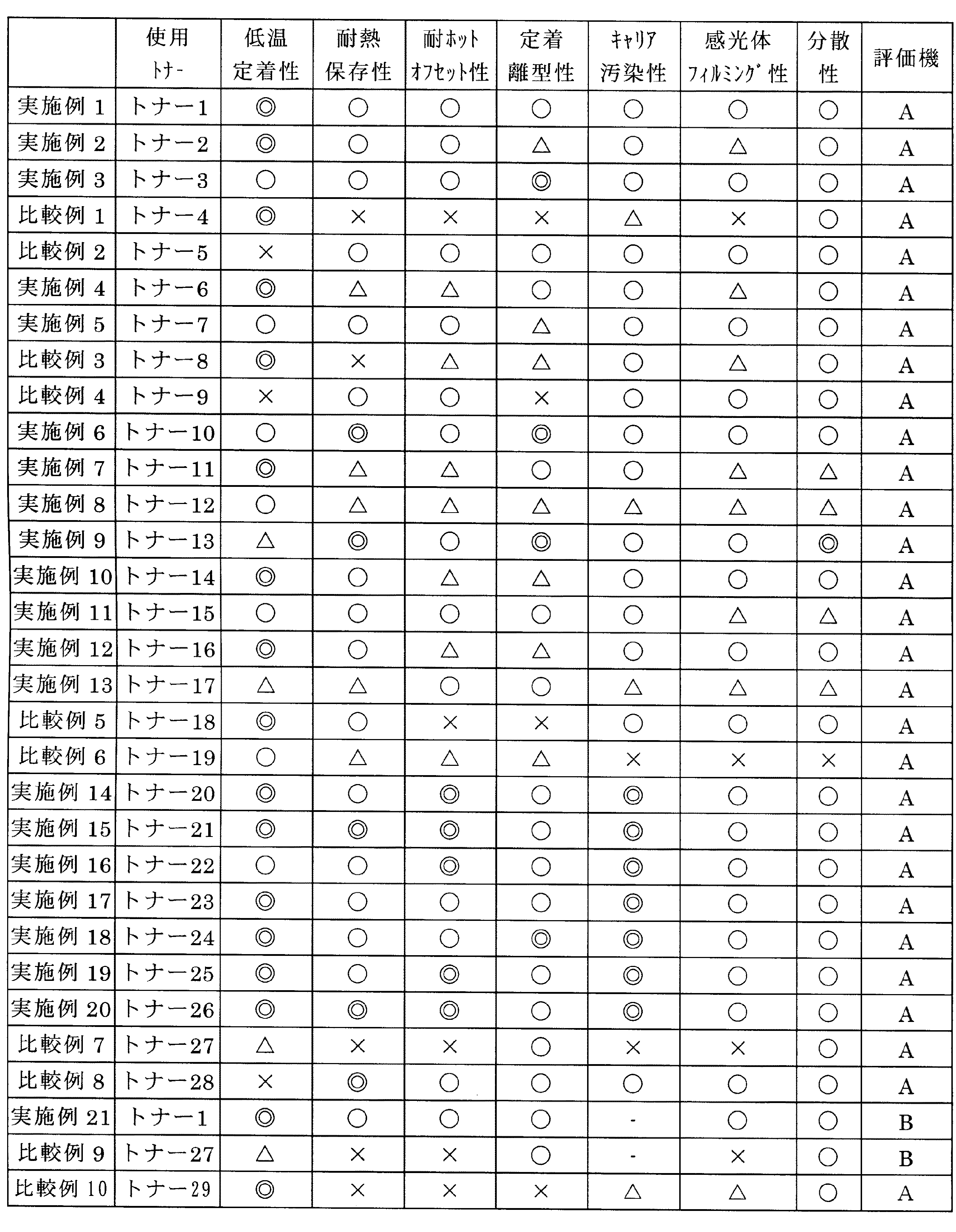
<サブレジンの製造例>
(ポリエステル樹脂の製造例)
窒素導入管、脱水管、攪拌器、及び温度計を備えた四つ口フラスコに、テレフタル酸150重量部、ビスフェノールA(2,2)プロピレンオキサイド207重量部、ビスフェノールA(2,2)エチレンオキサイド127重量部、エステル化触媒としてジブチル錫オキシド2.5重量部を投入し、窒素雰囲気下、230℃で15時間縮重合反応させた後、230℃、8.0kPaにて1時間反応を行った。180℃まで冷却した後、無水トリメリット酸115重量部を投入し、210℃まで3時間かけて昇温を行い、常圧(101.3kPa)下、10時間反応させた後に、210℃、20kPaにて3時間反応を行って、ポリエステル樹脂A(Mw1.5×104、Mw/Mn4.6、Tg60℃)を合成した。
<Production example of subresin>
(Production example of polyester resin)
In a four-necked flask equipped with a nitrogen introduction tube, a dehydration tube, a stirrer, and a thermometer, 150 parts by weight of terephthalic acid, 207 parts by weight of bisphenol A (2,2) propylene oxide, and bisphenol A (2,2) ethylene oxide 127 parts by weight and 2.5 parts by weight of dibutyltin oxide as an esterification catalyst were charged and subjected to a condensation polymerization reaction at 230 ° C. for 15 hours in a nitrogen atmosphere, and then reacted at 230 ° C. and 8.0 kPa for 1 hour. . After cooling to 180 ° C., 115 parts by weight of trimellitic anhydride was added, the temperature was raised to 210 ° C. over 3 hours, and the reaction was carried out at normal pressure (101.3 kPa) for 10 hours, followed by 210 ° C. and 20 kPa. and reacted for 3 hours at, polyester resin a (Mw1.5 × 10 4, Mw / Mn4.6, Tg60 ℃) was synthesized.
(ビニル系樹脂の製造例)
窒素導入管、脱水管、攪拌器、及び温度計を備えた四つ口フラスコに、スチレン440重量部、メタクリル酸105重量部、メタクリル酸ブチル68重量部、重合開始剤としてt−ブチルハイドロパーオキサイド40重量部を投入し、窒素雰囲気下、135℃で撹拌を行いながら6時間反応を行って、ビニル系樹脂A(スチレン−メタクリル酸−メタクリル酸ブチル共重合体、Mw5.2×104、Mw/Mn7.3、Tg65℃)を合成した。
(Examples of vinyl resin production)
In a four-necked flask equipped with a nitrogen introduction tube, a dehydration tube, a stirrer, and a thermometer, 440 parts by weight of styrene, 105 parts by weight of methacrylic acid, 68 parts by weight of butyl methacrylate, and t-butyl hydroperoxide as a
<マスターバッチの製造例>
(マスターバッチの製造例1)
下記の組成の顔料、環化ゴム、及び純水を1:1:0.5(重量比)の割合で、混合して、2本ロールにより混練した。混練は80℃で行い、その後、ロール温度を130℃まで上げて、水を蒸発させて、シアンマスターバッチ1(MB−C1)、マゼンタマスターバッチ1(MB−M1)、イエローマスターバッチ1(MB−Y1)、及びブラックマスターバッチ1(MB−K1)からなるマスターバッチ1(MB−1)を作製した。
<Example of master batch production>
(Manufacture example 1 of a master batch)
A pigment having the following composition, cyclized rubber, and pure water were mixed at a ratio of 1: 1: 0.5 (weight ratio) and kneaded by two rolls. The kneading is performed at 80 ° C., and then the roll temperature is increased to 130 ° C. to evaporate water, and cyan master batch 1 (MB-C1), magenta master batch 1 (MB-M1), yellow master batch 1 (MB -Y1) and master batch 1 (MB-1) consisting of black master batch 1 (MB-K1) were produced.
〔シアントナーマスターバッチ1(MB−C1)処方〕
環化ポリイソプレンA・・・100重量部
シアン顔料(C.I.Pigment blue 15:3)・・・100重量部
純水・・・50重量部
[Cyan toner masterbatch 1 (MB-C1) formulation]
Cyclized polyisoprene A: 100 parts by weight Cyan pigment (CI Pigment blue 15: 3): 100 parts by weight Pure water: 50 parts by weight
〔マゼンタトナーマスターバッチ1(MB−M1)処方〕
環化ポリイソプレンA・・・100重量部
マゼンタ顔料(C.I.Pigment red 122)・・・100重量部
純水・・・50重量部
[Magenta Toner Masterbatch 1 (MB-M1) prescription]
Cyclized polyisoprene A: 100 parts by weight Magenta pigment (CI Pigment red 122): 100 parts by weight Pure water: 50 parts by weight
〔イエロートナーマスターバッチ1(MB−Y1)処方〕
環化ポリイソプレンA・・・100重量部
イエロー顔料(C.I.Pigment yellow 180)・・・100重量部
純水・・・50重量部
[Yellow toner masterbatch 1 (MB-Y1) formulation]
Cyclized polyisoprene A: 100 parts by weight Yellow pigment (CI Pigment yellow 180): 100 parts by weight Pure water: 50 parts by weight
〔ブラックトナーマスターバッチ1(MB−K1)処方〕
環化ポリイソプレンA・・・100重量部
ブラック顔料(カーボンブラック)・・・100重量部
純水・・・50重量部
[Black Toner Masterbatch 1 (MB-K1) prescription]
Cyclized polyisoprene A: 100 parts by weight Black pigment (carbon black): 100 parts by weight Pure water: 50 parts by weight
(マスターバッチの製造例2)
マスターバッチの製造例1において、環化ポリイソプレンAを環化ポリイソプレンBに変えた以外は、マスターバッチの製造例1と同様にして、シアンマスターバッチ2(MB−C2)、マゼンタマスターバッチ2(MB−M2)、イエローマスターバッチ2(MB−Y2)、及びブラックマスターバッチ2(MB−K2)からなるマスターバッチ2(MB−2)を作製した。
(Manufacture example 2 of master batch)
Cyan masterbatch 2 (MB-C2) and
(マスターバッチの製造例3)
マスターバッチの製造例1において、環化ポリイソプレンAを環化ポリイソプレンCに変えた以外は、マスターバッチの製造例1と同様にして、シアンマスターバッチ3(MB−C3)、マゼンタマスターバッチ3(MB−M3)、イエローマスターバッチ3(MB−Y3)、及びブラックマスターバッチ3(MB−K3)からなるマスターバッチ3(MB−3)を作製した。
(Manufacture example 3 of a master batch)
In master batch production example 1, cyan master batch 3 (MB-C3), magenta master batch 3 were the same as in master batch production example 1 except that cyclized polyisoprene A was changed to cyclized polyisoprene C. Master batch 3 (MB-3) consisting of (MB-M3), yellow master batch 3 (MB-Y3), and black master batch 3 (MB-K3) was produced.
(マスターバッチの製造例4)
マスターバッチの製造例1において、環化ポリイソプレンAを環化ポリイソプレンDに変えた以外は、マスターバッチの製造例1と同様にして、シアンマスターバッチ4(MB−C4)、マゼンタマスターバッチ4(MB−M4)、イエローマスターバッチ4(MB−Y4)、及びブラックマスターバッチ4(MB−K4)からなるマスターバッチ4(MB−4)を作製した。
(Manufacture example 4 of a master batch)
Cyan masterbatch 4 (MB-C4) and magenta masterbatch 4 were the same as in Masterbatch Production Example 1 except that cyclized polyisoprene A was changed to cyclized polyisoprene D in Masterbatch Production Example 1. Master batch 4 (MB-4) consisting of (MB-M4), yellow master batch 4 (MB-Y4), and black master batch 4 (MB-K4) was produced.
(マスターバッチの製造例5)
マスターバッチの製造例1において、環化ポリイソプレンAを環化ポリイソプレンEに変えた以外は、マスターバッチの製造例1と同様にして、シアンマスターバッチ5(MB−C5)、マゼンタマスターバッチ5(MB−M5)、イエローマスターバッチ5(MB−Y5)、及びブラックマスターバッチ5(MB−K5)からなるマスターバッチ5(MB−5)を作製した。
(Manufacture example 5 of a master batch)
Cyan masterbatch 5 (MB-C5) and magenta masterbatch 5 were the same as in Masterbatch Production Example 1 except that cyclized polyisoprene A was changed to cyclized polyisoprene E in Masterbatch Production Example 1. Master batch 5 (MB-5) consisting of (MB-M5), yellow master batch 5 (MB-Y5), and black master batch 5 (MB-K5) was produced.
(マスターバッチの製造例6)
マスターバッチの製造例1において、環化ポリイソプレンAを環化ポリイソプレンFに変えた以外は、マスターバッチの製造例1と同様にして、シアンマスターバッチ6(MB−C6)、マゼンタマスターバッチ6(MB−M6)、イエローマスターバッチ6(MB−Y6)、及びブラックマスターバッチ6(MB−K6)からなるマスターバッチ6(MB−6)を作製した。
(Master batch production example 6)
Cyan masterbatch 6 (MB-C6), magenta masterbatch 6 were the same as masterbatch production example 1 except that cyclized polyisoprene A was changed to cyclized polyisoprene F in master batch production example 1. Master batch 6 (MB-6) consisting of (MB-M6), yellow master batch 6 (MB-Y6), and black master batch 6 (MB-K6) was produced.
(マスターバッチの製造例7)
マスターバッチの製造例1において、環化ポリイソプレンAを環化ポリイソプレンGに変えた以外は、マスターバッチの製造例1と同様にして、シアンマスターバッチ7(MB−C7)、マゼンタマスターバッチ7(MB−M7)、イエローマスターバッチ7(MB−Y7)、及びブラックマスターバッチ7(MB−K7)からなるマスターバッチ7(MB−7)を作製した。
(Manufacture example 7 of a master batch)
Cyan masterbatch 7 (MB-C7) and magenta masterbatch 7 were the same as masterbatch production example 1 except that cyclized polyisoprene A was changed to cyclized polyisoprene G in master batch production example 1. Master batch 7 (MB-7) consisting of (MB-M7), yellow master batch 7 (MB-Y7), and black master batch 7 (MB-K7) was produced.
(マスターバッチの製造例8)
マスターバッチの製造例1において、環化ポリイソプレンAを環化ポリブタジエンAに変えた以外は、マスターバッチの製造例1と同様にして、シアンマスターバッチ8(MB−C8)、マゼンタマスターバッチ8(MB−M8)、イエローマスターバッチ8(MB−Y8)、及びブラックマスターバッチ8(MB−K8)からなるマスターバッチ8(MB−8)を作製した。
(Master batch production example 8)
In the master batch production example 1, except that the cyclized polyisoprene A was changed to cyclized polybutadiene A, a cyan master batch 8 (MB-C8), a magenta master batch 8 ( A master batch 8 (MB-8) consisting of MB-M8), yellow master batch 8 (MB-Y8), and black master batch 8 (MB-K8) was produced.
<トナーの製造例>
(トナーの製造例1)
以下のようにして、シアントナー1、マゼンタトナー1、イエロートナー1、及びブラックトナー1からなるトナー1を製造した。
<Example of toner production>
(Toner Production Example 1)
In the following manner,
〔シアントナー1の製造〕
下記の表2に示すトナー1の原材料である結着樹脂、ワックス、マスターバッチ4色の内シアンマスターバッチ及び無機微粒子を、表2に示される各々の処方量で、へンシェルミキサー(三井三池化工機株式会社製、FM10B)を用いて予備混合した後、二軸混練機(株式会社池貝製、PCM−30)で100〜130℃の温度で溶融、混練した。得られた混練物は室温まで冷却後、ハンマーミルにて200〜300μmに粗粉砕した。次いで、超音速ジェット粉砕機ラボジェット(日本ニューマチック工業株式会社製)を用いて、重量平均粒径が6.2±0.3μmとなるように粉砕エアー圧を適宜調整しながら微粉砕した後、気流分級機(日本ニューマチック工業株式会社製、MDS−I)で、重量平均粒径が7.0±0.2μm、4μm以下の微粉量が10個数%以下となるようにルーバー開度を適宜調整しながら分級し、トナー母体粒子を得た。なお、上記無機微粒子としては、炭酸カルシウム(粒径500〜1000nm)を使用し内添した。
[Production of Cyan Toner 1]
The Henschel mixer (Mitsui Mitsui) is a raw material for
次いで、トナー母体粒子100重量部に対し、添加剤(HDK−2000、クラリアント株式会社製)1.0重量部をヘンシェルミキサーで撹拌混合し、シアントナー1を製造した。
Next, 1.0 part by weight of an additive (HDK-2000, manufactured by Clariant Co., Ltd.) was stirred and mixed with a Henschel mixer with respect to 100 parts by weight of toner base particles to produce
なお、表2〜6に記載されている環状オレフィンAとは、ノルボルネン−エチレン共重合体(TOPAS COC、ティコナジャパン(株)製、Mw1.8×104、Mw/Mn2.0、Tg62℃)である。また、ワックスA1は融点78℃のパラフィンワックス(日本精蝋(株)製)、ワックスA2は融点53℃のパラフィンワックス(日本精蝋(株)製)、ワックスA3は融点85℃のパラフィンワックス(日本精蝋(株)製)、ワックスA4は融点47℃のパラフィンワックス(フィッシャートロプシュワックス)(日本精蝋(株)製)、ワックスA5は融点93℃のパラフィンワックス(フィッシャートロプシュワックス)(日本精蝋(株)製)、ワックスB1は融点95℃のポリエチレンワックス、ワックスB2は融点70℃のポリエチレンワックス、ワックスB3は融点145℃のポリプロピレンワックス、ワックスB4は融点68℃のポリエチレンワックス、ワックスB5は融点153℃のポリプロピレンワックスである。 In addition, the cyclic olefin A described in Tables 2 to 6 is a norbornene-ethylene copolymer (TOPAS COC, manufactured by Ticona Japan, Mw1.8 × 10 4 , Mw / Mn2.0, Tg62 ° C. ). Wax A1 is a paraffin wax having a melting point of 78 ° C. (manufactured by Nippon Seiwa Co., Ltd.), wax A2 is a paraffin wax having a melting point of 53 ° C. (manufactured by Nippon Seiwa Co., Ltd.), and wax A3 is a paraffin wax having a melting point of 85 ° C. Nippon Seiwa Co., Ltd.), wax A4 is a paraffin wax (Fischer Tropsch wax) having a melting point of 47 ° C. (manufactured by Nippon Seiwa Co., Ltd.), and wax A5 is a paraffin wax having a melting point of 93 ° C. (Fischer Tropsch wax) (Nippon Seiki) Wax B1 is a polyethylene wax having a melting point of 95 ° C, Wax B2 is a polyethylene wax having a melting point of 70 ° C, Wax B3 is a polypropylene wax having a melting point of 145 ° C, Wax B4 is a polyethylene wax having a melting point of 68 ° C, and Wax B5 is Polypropylene wax having a melting point of 153 ° C.
(環化ゴムとワックスの相溶性の評価)
ワックスの環化ゴムに対する相溶性の評価は、上記<トナーの製造例1>に記したトナー製造方法に準じて、環化ゴム90重量部とワックス(A)10重量部、もしくは環化ゴム90重量部とワックス(B)10重量部をへンシェルミキサー(三井三池化工機株式会社製、FM10B)を用いて予備混合した後、二軸混練機(株式会社池貝製、PCM−30)で100〜130℃の温度で溶融、混練したのち、得られた混練物を室温まで冷却後、ハンマーミルにて200〜300μmに粗粉砕したものの軟化温度〔T(F1/2)〕を測定することで評価した。
ここで、軟化温度〔T(F1/2)〕とは、島津製作所製 高架式フローテスターCF−500を使用し、ダイス径1mm、加圧10kgf/cm2、昇温速度3℃/minの条件下で1cm3の試料を溶融流出させた時のストロークが、流出開始点から流出終了点までのストローク変化量の1/2になる時の温度である。
(Evaluation of compatibility between cyclized rubber and wax)
The compatibility of the wax with the cyclized rubber was evaluated according to the toner production method described in <Toner Production Example 1> above, 90 parts by weight of cyclized rubber and 10 parts by weight of wax (A), or 90 parts of cyclized rubber. Part by weight and 10 parts by weight of wax (B) were premixed using a Henschel mixer (Mitsui Miike Chemical Co., Ltd., FM10B), and then mixed with a biaxial kneader (Ikegai Co., Ltd., PCM-30). After melting and kneading at a temperature of ˜130 ° C., the obtained kneaded product is cooled to room temperature and then coarsely pulverized to 200 to 300 μm with a hammer mill to measure the softening temperature [T (F1 / 2)]. evaluated.
Here, the softening temperature [T (F1 / 2)] is a condition using an elevated flow tester CF-500 manufactured by Shimadzu Corporation, a die diameter of 1 mm, a pressure of 10 kgf / cm 2 , and a temperature rising rate of 3 ° C./min. This is the temperature at which the stroke when the sample of 1 cm 3 is melted and discharged is ½ of the stroke change amount from the outflow start point to the outflow end point.
〔マゼンタトナー1の製造〕
シアントナー1の製造方法において、表2に示すトナー1の使用原料であるマスターバッチの内シアンマスターバッチの代わりに、マゼンタマスターバッチを、表2に示す処方量で使用したこと以外は、シアントナー1の製造方法と同様にして、マゼンタトナー1を製造した。
[Manufacture of magenta toner 1]
In the method for producing
〔イエロートナー1の製造〕
シアントナー1の製造方法において、表2に示すトナー1の使用原料であるマスターバッチの内シアンマスターバッチの代わりに、イエローマスターバッチを、表2に示す処方量で使用したこと以外は、シアントナー1の製造方法と同様にして、イエロートナー1を製造した。
[Production of Yellow Toner 1]
In the
〔ブラックトナー1の製造〕
シアントナー1の製造方法において、表2に示すトナー1の使用原料であるマスターバッチの内シアンマスターバッチの代わりに、ブラックマスターバッチを、表2に示す処方量で使用したこと以外は、シアントナー1の製造方法と同様にして、ブラックトナー1を製造した。
[Production of Black Toner 1]
In the method for producing
(トナーの製造例2〜29)
上記トナー1の製造例と同様にして、シアントナー2〜29、マゼンタトナー2〜29、イエロートナー2〜29、及びブラックトナー2〜29からなるトナー2〜29を、表2〜表6に示される原料の組合せ及び処方量でそれぞれ製造した。
(Toner Production Examples 2 to 29)
Tables 2 to 6
なお、表2〜6中、太字は、次の性能評価において、比較例となる処方を示す。また、括弧内の数値は処方量(重量部)を示す。 In Tables 2 to 6, bold letters indicate prescriptions serving as comparative examples in the next performance evaluation. Moreover, the numerical value in parenthesis shows a prescription amount (part by weight).
(トナーの性能評価方法)
次に、得られたトナー1〜29について、以下のようにして、耐熱保存性と粉砕性(トナー中の分散状態)を評価した。結果を表7に示す。
(Toner performance evaluation method)
Next, the obtained
(トナーの耐熱保存性)
耐熱保存性は、針入度試験器(日科エンジニアリング株式会社製)を用いて測定した。具体的には、各トナーを10g計量し、温度20〜25℃、40〜60%RHの環境下で30mlのガラス容器(スクリューバイアル)に入れ、蓋を閉めた。トナーを入れたガラス容器を100回タッピングした後、温度を50℃にセットした恒温槽に24時間放置した後、針入度試験器で針入度を測定し、下記の評価基準により耐熱保存性を評価した。針入度の値が大きいほど、耐熱保存性に優れる。なお、各トナー4色の測定結果の内、最も悪い結果をそのトナーの評価値とした。
〔評価基準〕
◎:針入度が30mm以上
○:針入度が20mm〜29mm
△:針入度が15mm〜19mm
×:針入度が8mm〜14mm
××:針入度が7mm以下
(Heat resistant storage stability of toner)
The heat-resistant storage stability was measured using a penetration tester (manufactured by Nikka Engineering Co., Ltd.). Specifically, 10 g of each toner was weighed and placed in a 30 ml glass container (screw vial) in an environment of 20 to 25 ° C. and 40 to 60% RH, and the lid was closed. After tapping the glass container containing the
〔Evaluation criteria〕
◎: Needle penetration is 30 mm or more ○: Needle penetration is 20 mm to 29 mm
Δ: penetration is 15 mm to 19 mm
X: The penetration is 8 mm to 14 mm
XX: Needle penetration is 7mm or less
(トナー中の分散状態)
トナー粒子を約100nmに超薄切片化し、四酸化ルテニウムにより染色した後、透過型電子顕微鏡(TEM)により倍率2万倍で観察を行ない写真撮影し分散状態をランク化し評価した。
分散状態:
トナー内部に
◎:非相溶のドメインがない
○:0.5μmを超える非相溶のドメインがない
△:1.5μmを超える非相溶のドメインがない
×:2μmを超える非相溶のドメインがない
(Dispersed state in toner)
The toner particles were cut into ultra-thin sections of about 100 nm, dyed with ruthenium tetroxide, and then observed with a transmission electron microscope (TEM) at a magnification of 20,000 to photograph and rank and evaluate the dispersion state.
Distributed state:
◎: No incompatible domain in the toner ○: No incompatible domain exceeding 0.5 μm Δ: No incompatible domain exceeding 1.5 μm ×: Incompatible domain exceeding 2 μm There is no
(画像形成装置Aを用いたトナーの評価)
以上作製したトナー1〜29を下記キャリアと混合し、図20に示す画像形成装置Aに装填して、画像形成を行い、以下のようにして、低温定着性、耐ホットオフセット性、定着離型性、キャリア汚染性、感光体フィルミング性の評価を行った。結果を表7に示す。
図20に示す画像形成装置Aは、非接触帯電方式、二成分現像方式、二次転写方式、ブレードクリーニング方式、及び外部加熱のローラ定着方式を採用した間接転写方式のタンデム型画像形成装置である。
図20に示す画像形成装置Aにおいて、帯電手段311として図3に示すような非接触のコロナ帯電器を採用している。現像手段324として図6に示すような二成分現像装置を採用している。クリーニング手段330として図10に示すようなクリーニングブレードを採用している。定着手段327として図12に示すような電磁誘導加熱方式のローラ式定着装置を採用している。
図20に示す画像形成装置Aにおける画像形成要素351は、感光体ドラム321の周辺に帯電手段311、露光手段323、現像手段324、一次転写手段325、クリーニング手段330が配設されている。画像形成要素351における感光体ドラム321は、回転しながら、帯電手段310による帯電、露光手段323による露光により、その表面に露光像に対応する静電潜像が形成される。この静電潜像は、現像手段324でイエロートナーにより現像され、感光体ドラム321上にイエロートナーによる可視像が形成される。この可視像が一次転写手段325によって中間転写ベルト355上に転写され、クリーニング手段330によって感光体ドラム321上に残ったイエロートナーが除去される。同様にして、各画像形成要素352、353、354によって、中間転写ベルト355上にマゼンタトナー、シアントナー、及びブラックトナーによる可視像が形成される。そして中間転写ベルト355上のカラー画像は、転写器356によって記録媒体326上に転写され、中間転写ベルトクリーニング手段358によって中間転写ベルト355上に残ったトナーが除去される。記録媒体326上に形成されたカラー画像は定着手段327によって定着される。
(Evaluation of toner using image forming apparatus A)
The
An image forming apparatus A shown in FIG. 20 is an indirect transfer type tandem type image forming apparatus that employs a non-contact charging method, a two-component development method, a secondary transfer method, a blade cleaning method, and an external heating roller fixing method. .
In the image forming apparatus A shown in FIG. 20, a non-contact corona charger as shown in FIG. As the developing
An
(キャリアの製造)
下記処方のコート材を10分間スターラーで分散してコート液を調製し、このコート液と、芯材(Cu−Znフェライト粒子、重量平均径=35μm)5,000重量部を流動床内に回転式底板ディスクと攪拌羽根を設けた旋回流を形成させながらコートを行うコーティング装置に投入して、コート液を芯材上に塗布した。得られた塗布物を電気炉で250℃、2時間焼成して、キャリアを作製した。
〔コート材処方〕
トルエン・・・450重量部
シリコーン樹脂(SR2400、東レ・ダウコーニング・シリコーン株式会社製、不揮発分50重量%)・・・450重量部
アミノシラン(SH6020、東レ・ダウコーニング・シリコーン株式会社製)・・・10重量部
カーボンブラック・・・10重量部
(Carrier production)
A coating material having the following formulation is dispersed with a stirrer for 10 minutes to prepare a coating solution, and 5,000 parts by weight of this coating solution and a core material (Cu—Zn ferrite particles, weight average diameter = 35 μm) are rotated in a fluidized bed. The coating liquid was applied to the core material by applying it to a coating apparatus for coating while forming a swirling flow provided with a type bottom plate disk and stirring blades. The obtained coated material was baked in an electric furnace at 250 ° C. for 2 hours to prepare a carrier.
[Coating material prescription]
Toluene: 450 parts by weight Silicone resin (SR2400, manufactured by Toray Dow Corning Silicone Co., Ltd., nonvolatile content: 50% by weight): 450 parts by weight Aminosilane (SH6020, manufactured by Toray Dow Corning Silicone Co., Ltd.)・ 10 parts by weight Carbon black ... 10 parts by weight
(二成分現像剤の作製)
作製したトナー1〜29を各5重量%と、上記作製したキャリア95重量%からなる二成分現像剤を常法により調製した。
(Preparation of two-component developer)
A two-component developer composed of 5% by weight of each of the
(定着性)
<低温定着性>
前記評価機を用い、厚紙の転写紙(株式会社NBSリコー製、複写印刷用紙〈135〉)に、ブラック、シアン、マゼンタ、イエローの各色で、トナー付着量0.85±0.1mg/cm2の単色ベタ画像を作成し、定着ローラ又はベルトの温度を変化させて定着を行い、得られた定着画像表面を描画試験器(AD−401、上島製作所製)を用いて、ルビー針(先端半径260〜320μmR、先端角60度)、荷重50gで描画し、繊維(ハニコット#440、ハニロン社製)で描画表面を強く5回擦り、画像の削れが殆ど無くなる定着ベルト温度をもって定着下限温度とし、下記基準により低温定着性を評価した。なお、ベタ画像は転写紙上において、通紙方向先端から3.0cmの位置に作成した。また、各トナー4色の測定結果の内、最も悪い結果をそのトナーの評価値とした。
〔評価基準〕
◎:定着下限温度が110℃以下
○:定着下限温度が111℃以上120℃以下
△:定着下限温度が121℃以上135℃以下
×:定着下限温度が136℃以上140℃以下
××:定着下限温度が141℃以上
(Fixability)
<Low temperature fixability>
Using the evaluation machine, the toner adhesion amount 0.85 ± 0.1 mg / cm 2 for each of black, cyan, magenta and yellow on a thick transfer paper (manufactured by NBS Ricoh Co., Ltd., copy printing paper <135>). A single color solid image is prepared, fixing is performed by changing the temperature of the fixing roller or belt, and the surface of the obtained fixed image is drawn on a ruby needle (tip radius) using a drawing tester (AD-401, manufactured by Ueshima Seisakusho). 260 ° to 320 μm R,
〔Evaluation criteria〕
A: Fixing lower limit temperature is 110 ° C. or less ○: Fixing lower limit temperature is 111 ° C. or more and 120 ° C. or less Δ: Fixing lower limit temperature is 121 ° C. or more and 135 ° C. or less ×: Fixing lower limit temperature is 136 ° C. or more and 140 ° C. or less XX: Fixing lower limit temperature Temperature is 141 ℃ or more
<耐ホットオフセット性>
前記評価機を用い、普通紙の転写紙(株式会社リコー製、タイプ6200)に、ブラック、シアン、マゼンタ、イエローの各色で、トナー付着量0.85±0.1mg/cm2の単色ベタ画像を作成し、定着ローラ又はベルトの温度を変化させて定着試験を行い、ホットオフセットの有無を目視評価し、ホットオフセットが発生しない上限温度を定着上限温度とし、下記基準で耐ホットオフセット性を評価した。なお、ベタ画像は転写紙上において、通紙方向先端から3.0cmの位置に作成した。なお、各トナー4色の測定結果の内、最も悪い結果をそのトナーの評価値とした。
〔評価基準〕
◎:定着上限温度が220℃以上
○:定着上限温度が210℃以上220℃未満
△:定着上限温度が190℃以上210℃未満
×:定着上限温度が180℃以上190℃未満
××:定着上限温度が180℃未満
<Hot offset resistance>
Using the evaluation machine, a solid solid image having a toner adhesion amount of 0.85 ± 0.1 mg / cm 2 in black, cyan, magenta, and yellow on plain paper transfer paper (type 6200, manufactured by Ricoh Co., Ltd.). A fixing test is performed by changing the temperature of the fixing roller or belt, and the presence or absence of hot offset is visually evaluated. The upper limit temperature at which hot offset does not occur is set as the upper limit fixing temperature, and the hot offset resistance is evaluated according to the following criteria. did. The solid image was created on the transfer paper at a position of 3.0 cm from the front end in the paper passing direction. Of the measurement results for the four colors of each toner, the worst result was taken as the evaluation value for that toner.
〔Evaluation criteria〕
A: Fixing upper limit temperature is 220 ° C. or more. ○: Fixing upper limit temperature is 210 ° C. or more and less than 220 ° C. Δ: Fixing upper limit temperature is 190 ° C. or more and less than 210 ° C. ×: Fixing upper limit temperature is 180 ° C. or more and less than 190 ° C. Temperature is less than 180 ° C
(定着離型性)
前記評価機を用い、薄紙の転写紙(株式会社リコー製、複写印刷用紙〈55〉)にトナー付着量0.85±0.1mg/cm2のベタ画像を作成し、定着ローラ又はベルトの温度を変化させて定着試験を行い、定着ニップ出口付近に定着紙と定着ベルトを分離させる為に配置された分離爪に、A4横方向に排紙された定着画像が接触することで発生する定着画像上の傷跡の程度を目視評価した。傷跡の程度は、ランク見本により5段階で評価され、傷跡若しくはジャムが全く発生しない上限温度を定着離型性の指標とした。なお、ベタ画像は転写紙上において、通紙方向先端から0.5cmの位置に作成した。
〔評価基準〕
◎:上限温度が200℃以上
○:上限温度が190℃以上200℃未満
△:上限温度が170℃以上190℃未満
×:上限温度が160℃以上170℃未満
××:上限温度が160℃未満
(Fixing releasability)
Using the evaluation machine, a solid image with a toner adhesion amount of 0.85 ± 0.1 mg / cm 2 was prepared on a thin transfer paper (manufactured by Ricoh Co., Ltd., copy printing paper <55>), and the temperature of the fixing roller or belt A fixed image generated by a fixed image ejected in the A4 lateral direction contacting a separation claw arranged to separate the fixing paper and the fixing belt near the fixing nip exit. The extent of the upper scar was visually evaluated. The extent of the scar was evaluated in five stages using a rank sample, and an upper limit temperature at which no scar or jam was generated was used as an index for fixing releasability. The solid image was created on the transfer paper at a position 0.5 cm from the front end in the paper passing direction.
〔Evaluation criteria〕
◎: Upper limit temperature is 200 ° C or higher ○: Upper limit temperature is 190 ° C or higher and lower than 200 ° C △: Upper limit temperature is 170 ° C or higher and lower than 190 ° C ×: Upper limit temperature is 160 ° C or higher and lower than 170 ° C XX: Upper limit temperature is lower than 160 ° C
(キャリア汚染性)
キャリア汚染性は、トナーのキャリア汚染の指標となる特性であり、トナーの機械的強度が高い程、キャリア汚染が少ない。評価法として具体的には、上記評価機を用い、単色モードで50%画像面積の画像チャートを100枚ランニング出力した後と30,000枚ランニング出力した後の現像剤を抜き取り、現像剤を目開き32μmのメッシュが張られたゲージ内に適量入れ、エアブローを行い、トナーとキャリアを分離した。得られたキャリア1.0gを50mlガラス瓶に入れ、クロロホルム10mlを加えて、50回手振りして、10分間静置させた。その後、上澄みのクロロホルム溶液をガラスセルに入れ、濁度計を用いてクロロホルム溶液の透過率を測定し、下記基準により評価した。
〔評価基準〕
◎:透過率が95%以上
○:透過率が90%以上94%以下
△:透過率が80%以上89%以下
×:透過率が70%以上79%以下
××:透過率が69%以下
(Carrier contamination)
The carrier contamination property is a characteristic that serves as an index of toner carrier contamination. The higher the mechanical strength of the toner, the less the carrier contamination. Specifically, as the evaluation method, using the above-described evaluation machine, the developer after 100 sheets running output of 50% image area image output in monochrome mode and after 30,000 sheets running output are extracted, and the developer is checked. An appropriate amount was placed in a gauge with a mesh having an opening of 32 μm, and air blowing was performed to separate the toner and the carrier. 1.0 g of the obtained carrier was put in a 50 ml glass bottle, 10 ml of chloroform was added, and the mixture was shaken 50 times and allowed to stand for 10 minutes. Thereafter, the supernatant chloroform solution was placed in a glass cell, and the transmittance of the chloroform solution was measured using a turbidimeter, and evaluated according to the following criteria.
〔Evaluation criteria〕
◎: Transmittance is 95% or more ○: Transmittance is 90% or more and 94% or less △: Transmittance is 80% or more and 89% or less ×: Transmittance is 70% or more and 79% or less XX: Transmittance is 69% or less
(感光体フィルミング性)
前記評価機を用い、単色モードで50%画像面積の画像チャートを100枚ランニング出力した後と50,000枚ランニング出力した後に、感光体上のトナーフィルミング状態を目視評価した。出力画像の異常の有無も考慮し、以下の5段階に分けて判定した。
〔評価基準〕
◎:画像異常が全くなく、感光体上のトナーフィルミングはない。
○:画像異常が全くないが、感光体上にうっすらとトナーフィルミングが見られる。
△:若干の画像異常が見られ、感光体上にも明らかなトナーフィルミングが見られる。
×:明らかな画像異常が見られ、感光体上のトナーフィルミングがひどく、問題のあるレベル。
××:明らかな画像異常が見られ、感光体上のトナーフィルミングがひどく、正常な画像が得ることができない。
(Photoreceptor filming property)
Using the evaluation machine, the toner filming state on the photosensitive member was visually evaluated after running and outputting 100 sheets of an image chart having a 50% image area in a monochrome mode. Considering the presence or absence of abnormality in the output image, the determination was made in the following five stages.
〔Evaluation criteria〕
A: No image abnormality and no toner filming on the photoreceptor.
◯: There is no image abnormality at all, but a slight toner filming is seen on the photoreceptor.
Δ: Some image abnormality is observed, and clear toner filming is also observed on the photoreceptor.
X: Clear image abnormality was observed, toner filming on the photosensitive member was severe, and there was a problem level.
XX: Clear image abnormality is observed, toner filming on the photoconductor is severe, and a normal image cannot be obtained.
(画像形成装置Bを用いたトナーの評価)
(実施例17及び比較例13)
トナー1及び27について、図21に示す画像形成装置Bに装填して、画像形成を行い、以下のようにして、低温定着性、耐ホットオフセット性、定着離型性、感光体フィルミング性、初期画像品質、経時画像品質の評価を行った。結果を表7に示す。
図21に示す画像形成装置Bは、接触帯電方式、一成分現像方式、直接転写方式、クリーナーレス方式、及び内部加熱のベルト定着方式を採用した直接転写方式のタンデム型画像形成装置である。
図21に示す画像形成装置Bにおいて、帯電手段310として図1に示すような接触方式の帯電ローラを用いている。現像手段324として図5に示すような一成分現像装置を用いており、この現像装置が残留トナーを回収できるクリーナーレス方式を採用している。定着手段327として図9に示すようなベルト式定着装置を採用しており、この定着装置は、加熱ローラの熱源としてハロゲンランプを用いている。なお、図21中、330は搬送ベルトである。
図21に示す画像形成装置Bにおける画像形成要素341は、感光体ドラム321の周辺に帯電手段310、露光手段323、現像手段324、転写手段325が配設されている。画像形成要素341における感光体ドラム321は、回転しながら、帯電手段310による帯電、露光手段323による露光により、その表面に露光像に対応する静電潜像が形成される。この静電潜像は、現像手段324でイエロートナーにより現像され、感光体ドラム321上にイエロートナーによる可視像が形成される。この可視像は転写手段325により記録媒体326上に転写され、その後、現像手段324によって感光体ドラム321上に残ったトナーが回収される。同様にして、各画像形成要素342、343、344によって、記録媒体326上にマゼンタトナー、シアントナー、及びブラックトナーによる可視像が重ね合わされ、記録媒体326上に形成されたカラー画像が定着手段327によって定着される。
低温定着性、耐ホットオフセット性、定着離型性、感光体フィルミング性の評価は、画像形成装置Aの代わりに画像形成装置Bを使用したこと以外は前述と同様にして評価を行った。
(Evaluation of toner using image forming apparatus B)
(Example 17 and Comparative Example 13)
The
An image forming apparatus B shown in FIG. 21 is a tandem type image forming apparatus of a direct transfer method adopting a contact charging method, a one-component developing method, a direct transfer method, a cleanerless method, and an internally heated belt fixing method.
In the image forming apparatus B shown in FIG. 21, a contact-type charging roller as shown in FIG. 1 is used as the charging
The
Evaluation of low-temperature fixability, hot offset resistance, fixing releasability, and photoconductor filming was performed in the same manner as described above except that the image forming apparatus B was used instead of the image forming apparatus A.
表1〜表7から、トナーに使用される環化ゴムの環化率、ワックスA、Bの各融点、ワックスA、Bの環化ゴムに対する相溶性が、さらにまたワックスA、Bの含有量が、重要な因子となって、低温定着性、耐熱保存性、耐ホットオフセット性、定着離型性、感光体フィルミング性に作用することが明らかである。また、環化ゴムの重量平均分子量(Mw)、分子量分布(Mw/Mn)を適切に選択することが大切である。 From Tables 1 to 7, the cyclization rate of the cyclized rubber used in the toner, the melting points of the waxes A and B, the compatibility of the waxes A and B with the cyclized rubber, and the contents of the waxes A and B However, it is apparent that it acts as an important factor on low-temperature fixability, heat-resistant storage stability, hot offset resistance, fixing releasability, and photoconductor filming properties. It is also important to appropriately select the weight average molecular weight (Mw) and molecular weight distribution (Mw / Mn) of the cyclized rubber.
1 静電潜像担持体(感光体ドラム)
2 転写手段(一次転写手段)
3 搬送ベルト
4 中間転写体
5 二次転写手段
6 給紙装置
7 定着装置
8 クリーニング装置
9 中間転写体クリーニング装置
10 静電潜像担持体(感光体ドラム)
10K ブラック用静電潜像担持体
10Y イエロー用静電潜像担持体
10M マゼンタ用静電潜像担持体
10C シアン用静電潜像担持体
14 支持ローラ
15 支持ローラ
16 支持ローラ
17 中間転写クリーニング手段
18 画像形成手段
20 帯電ローラ
21 露光装置
22 二次転写手段
23 ローラ
24 二次転写ベルト
25 定着装置
26 定着ベルト
27 加圧ローラ
28 反転装置
30 露光装置
32 コンタクトガラス
33 第1走行体
34 第2走行体
35 結像レンズ
36 読取りセンサ
40 現像装置
41 現像ベルト
42K 現像剤収容部
42Y 現像剤収容部
42M 現像剤収容部
42C 現像剤収容部
43K 現像剤供給ローラ
43Y 現像剤供給ローラ
43M 現像剤供給ローラ
43C 現像剤供給ローラ
44K 現像ローラ
44Y 現像ローラ
44M 現像ローラ
44C 現像ローラ
45K ブラック用現像手段
45Y イエロー用現像手段
45M マゼンタ用現像手段
45C シアン用現像手段
49 レジストローラ
50 中間転写体
51 ローラ
52 分離ローラ
53 手差し給紙路
54 手差しトレイ
55 切換爪
56 排出ローラ
57 排出トレイ
58 コロナ帯電器
60 クリーニング手段
61 現像装置
62 転写帯電器
63 クリーニング装置
64 除電装置
70 除電ランプ
80 転写ローラ
90 クリーニング装置
95 記録媒体
100 画像形成装置
101 静電潜像担持体
102 帯電手段
103 露光手段
104 現像手段
105 記録媒体
107 クリーニング手段
108 転写手段
120 タンデム型現像手段
130 原稿台
142 給紙ローラ
143 ペーパーバンク
144 給紙カセット
145 分離ローラ
146 給紙路
147 搬送ローラ
148 給紙路
150 複写装置本体
160 帯電装置
200 給紙テーブル
220 加熱ローラ
230 加圧ローラ
300 スキャナ
302 フィルム
303 スプリング
310 帯電ローラ
311 芯金(帯電ローラの軸)
312 抵抗調整層
313 保護層
310 帯電ローラ
321 静電潜像担持体
323 露光手段
324 現像手段
325 転写手段
326 記録媒体
327 定着手段
330 クリーニング手段
331 除電装置
400 原稿自動搬送装置(ADF)
401 ケーシング
402 現像ローラ
411 アジテータ
412 供給ローラ
413 規制ブレード
510 ベルト式定着装置
511 加熱ローラ
512 定着ローラ
513 定着ベルト
514 加圧ローラ
515 熱ロール式定着装置
525 ロール式定着装置
570 電磁誘導加熱式定着装置
613 クリーニングブレード
S 記録媒体
P 記録媒体
1 Electrostatic latent image carrier (photosensitive drum)
2 Transfer means (primary transfer means)
DESCRIPTION OF SYMBOLS 3 Conveying belt 4 Intermediate transfer body 5 Secondary transfer means 6 Paper feeding device 7 Fixing device 8 Cleaning device 9 Intermediate transfer
10K Electrostatic latent image carrier for black 10Y Electrostatic latent image carrier for yellow 10M Electrostatic latent image carrier for magenta 10C Electrostatic latent image carrier for cyan 14 Support roller 15 Support roller 16 Support roller 17 Intermediate transfer cleaning means DESCRIPTION OF SYMBOLS 18 Image forming means 20 Charging roller 21 Exposure apparatus 22 Secondary transfer means 23 Roller 24 Secondary transfer belt 25 Fixing apparatus 26 Fixing belt 27 Pressure roller 28 Reversing apparatus 30 Exposure apparatus 32 Contact glass 33 First traveling body 34 Second traveling Body 35 Imaging lens 36 Reading sensor 40 Developing device 41 Developing belt 42K Developer container 42Y Developer container 42M Developer container 42C Developer container 43K Developer supply roller 43Y Developer supply roller 43M Developer supply roller 43C Developer supply roller 44K Development roller 4 4Y developing roller 44M developing roller 44C developing roller 45K black developing unit 45Y yellow developing unit 45M magenta developing unit 45C cyan developing unit 49 registration roller 50 intermediate transfer member 51 roller 52 separation roller 53 manual feed path 54 manual tray 55 Switching claw 56 Discharge roller 57 Discharge tray 58 Corona charger 60 Cleaning means 61 Developing device 62 Transfer charger 63 Cleaning device 64 Discharge device 70 Discharge lamp 80 Transfer roller 90 Cleaning device 95 Recording medium 100 Image forming device 101 Electrostatic latent image carrier Body 102 Charging means 103 Exposure means 104 Developing means 105 Recording medium 107 Cleaning means 108 Transfer means 120 Tandem developing means 130 Document table 142 Feed roller 143 Paper Link 144 Paper feed cassette 145 Separation roller 146 Paper feed path 147 Transport roller 148 Paper feed path 150 Copying device main body 160 Charging device 200 Paper feed table 220 Heating roller 230 Pressure roller 300 Scanner 302 Film 303 Spring 310 Charging roller 311 Core ( Charging roller shaft)
312
401
Claims (13)
Priority Applications (1)
| Application Number | Priority Date | Filing Date | Title |
|---|---|---|---|
| JP2008289916A JP5365773B2 (en) | 2008-07-30 | 2008-11-12 | Image forming toner, developer, toner container, image forming apparatus, image forming method, and process cartridge |
Applications Claiming Priority (3)
| Application Number | Priority Date | Filing Date | Title |
|---|---|---|---|
| JP2008195725 | 2008-07-30 | ||
| JP2008195725 | 2008-07-30 | ||
| JP2008289916A JP5365773B2 (en) | 2008-07-30 | 2008-11-12 | Image forming toner, developer, toner container, image forming apparatus, image forming method, and process cartridge |
Publications (2)
| Publication Number | Publication Date |
|---|---|
| JP2010055045A true JP2010055045A (en) | 2010-03-11 |
| JP5365773B2 JP5365773B2 (en) | 2013-12-11 |
Family
ID=42070989
Family Applications (1)
| Application Number | Title | Priority Date | Filing Date |
|---|---|---|---|
| JP2008289916A Expired - Fee Related JP5365773B2 (en) | 2008-07-30 | 2008-11-12 | Image forming toner, developer, toner container, image forming apparatus, image forming method, and process cartridge |
Country Status (1)
| Country | Link |
|---|---|
| JP (1) | JP5365773B2 (en) |
Cited By (2)
| Publication number | Priority date | Publication date | Assignee | Title |
|---|---|---|---|---|
| JP2015184574A (en) * | 2014-03-25 | 2015-10-22 | 富士ゼロックス株式会社 | Electrostatic charge image development toner, electrostatic charge image developer, toner cartridge, process cartridge, image forming apparatus, and image forming method |
| JP2017003901A (en) * | 2015-06-15 | 2017-01-05 | キヤノン株式会社 | toner |
Citations (3)
| Publication number | Priority date | Publication date | Assignee | Title |
|---|---|---|---|---|
| JP2002023411A (en) * | 2000-05-01 | 2002-01-23 | Ricoh Co Ltd | Electrophotographic toner |
| JP2004325843A (en) * | 2003-04-25 | 2004-11-18 | Tomoegawa Paper Co Ltd | Electrophotographic toner |
| JP2007079348A (en) * | 2005-09-16 | 2007-03-29 | Ricoh Co Ltd | Toner |
-
2008
- 2008-11-12 JP JP2008289916A patent/JP5365773B2/en not_active Expired - Fee Related
Patent Citations (3)
| Publication number | Priority date | Publication date | Assignee | Title |
|---|---|---|---|---|
| JP2002023411A (en) * | 2000-05-01 | 2002-01-23 | Ricoh Co Ltd | Electrophotographic toner |
| JP2004325843A (en) * | 2003-04-25 | 2004-11-18 | Tomoegawa Paper Co Ltd | Electrophotographic toner |
| JP2007079348A (en) * | 2005-09-16 | 2007-03-29 | Ricoh Co Ltd | Toner |
Cited By (2)
| Publication number | Priority date | Publication date | Assignee | Title |
|---|---|---|---|---|
| JP2015184574A (en) * | 2014-03-25 | 2015-10-22 | 富士ゼロックス株式会社 | Electrostatic charge image development toner, electrostatic charge image developer, toner cartridge, process cartridge, image forming apparatus, and image forming method |
| JP2017003901A (en) * | 2015-06-15 | 2017-01-05 | キヤノン株式会社 | toner |
Also Published As
| Publication number | Publication date |
|---|---|
| JP5365773B2 (en) | 2013-12-11 |
Similar Documents
| Publication | Publication Date | Title |
|---|---|---|
| JP4749939B2 (en) | Image forming apparatus, image forming method, and process cartridge | |
| JP5054443B2 (en) | Image forming apparatus, image forming method, and process cartridge | |
| JP4749937B2 (en) | Image forming apparatus, image forming method, and process cartridge | |
| JP4808695B2 (en) | Toner, image forming apparatus using the same, image forming method, and process cartridge | |
| JP4749925B2 (en) | Image forming apparatus, image forming method, and process cartridge | |
| JP5392450B2 (en) | White toner for electrophotography, image forming apparatus using the same, and image forming method | |
| JP2008129411A (en) | Toner, image forming apparatus and image forming method using the same, and process cartridge | |
| JP4749938B2 (en) | Image forming apparatus, image forming method, and process cartridge | |
| JP5245421B2 (en) | Toner production method | |
| JP4749929B2 (en) | Image forming apparatus, image forming method, and process cartridge | |
| JP4749940B2 (en) | Image forming apparatus, image forming method, and process cartridge | |
| JP4874878B2 (en) | Two-component developer, image forming apparatus using the same, image forming method, and process cartridge | |
| JP4971756B2 (en) | Toner, image forming apparatus using the same, image forming method, and process cartridge | |
| JP4749928B2 (en) | Image forming apparatus, image forming method, and process cartridge | |
| JP4909233B2 (en) | Image forming apparatus, image forming method, and process cartridge | |
| JP5625230B2 (en) | Toner, developer, and image forming apparatus | |
| JP4749927B2 (en) | Image forming apparatus, image forming method, and process cartridge | |
| JP4749924B2 (en) | Image forming apparatus, image forming method, and process cartridge | |
| JP2008129469A (en) | Developer, image forming apparatus using the same, image forming method using the same, and process cartridge | |
| JP5365773B2 (en) | Image forming toner, developer, toner container, image forming apparatus, image forming method, and process cartridge | |
| JP4749926B2 (en) | Image forming apparatus, image forming method, and process cartridge | |
| JP5002448B2 (en) | Image forming apparatus | |
| JP5439796B2 (en) | Toner, two-component developer, image forming method, image forming apparatus, and process cartridge | |
| JP2010066322A (en) | Toner for color image formation, toner kit using the same, full-color toner image forming apparatus, process cartridge, and full-color image forming method | |
| JP2010085456A (en) | Toner, developer, container containing toner, image forming device, image forming method, and process cartridge |
Legal Events
| Date | Code | Title | Description |
|---|---|---|---|
| A621 | Written request for application examination |
Free format text: JAPANESE INTERMEDIATE CODE: A621 Effective date: 20110913 |
|
| RD02 | Notification of acceptance of power of attorney |
Free format text: JAPANESE INTERMEDIATE CODE: A7422 Effective date: 20110920 |
|
| A977 | Report on retrieval |
Free format text: JAPANESE INTERMEDIATE CODE: A971007 Effective date: 20130307 |
|
| A131 | Notification of reasons for refusal |
Free format text: JAPANESE INTERMEDIATE CODE: A131 Effective date: 20130521 |
|
| A521 | Written amendment |
Free format text: JAPANESE INTERMEDIATE CODE: A523 Effective date: 20130710 |
|
| TRDD | Decision of grant or rejection written | ||
| A01 | Written decision to grant a patent or to grant a registration (utility model) |
Free format text: JAPANESE INTERMEDIATE CODE: A01 Effective date: 20130814 |
|
| A61 | First payment of annual fees (during grant procedure) |
Free format text: JAPANESE INTERMEDIATE CODE: A61 Effective date: 20130827 |
|
| R151 | Written notification of patent or utility model registration |
Ref document number: 5365773 Country of ref document: JP Free format text: JAPANESE INTERMEDIATE CODE: R151 |
|
| LAPS | Cancellation because of no payment of annual fees |