JP2010054822A - Image forming apparatus - Google Patents
Image forming apparatus Download PDFInfo
- Publication number
- JP2010054822A JP2010054822A JP2008219976A JP2008219976A JP2010054822A JP 2010054822 A JP2010054822 A JP 2010054822A JP 2008219976 A JP2008219976 A JP 2008219976A JP 2008219976 A JP2008219976 A JP 2008219976A JP 2010054822 A JP2010054822 A JP 2010054822A
- Authority
- JP
- Japan
- Prior art keywords
- image forming
- forming apparatus
- process unit
- unit
- old
- Prior art date
- Legal status (The legal status is an assumption and is not a legal conclusion. Google has not performed a legal analysis and makes no representation as to the accuracy of the status listed.)
- Granted
Links
Images


Landscapes
- Electrophotography Configuration And Component (AREA)
- Dry Development In Electrophotography (AREA)
Abstract
Description
本発明は、電子写真方式の画像形成装置において、プロセスユニットを備える画像形成装置に関する。 The present invention relates to an image forming apparatus having a process unit in an electrophotographic image forming apparatus.
電子写真方式の画像形成装置に使用される消耗品は、使用頻度に伴いいずれは交換すべき寿命に達する。トナーカートリッジであれば供給すべきトナーが容器内になくなったとき、プロセスユニットであれば現像剤が耐久劣化したとき、廃トナー容器であれば容器内が廃トナーでいっぱいになったとき、等が該当する。 Consumables used in electrophotographic image forming apparatuses eventually reach the end of their service life as they are used. For toner cartridges, there is no toner to be supplied in the container, for process units, when the developer has deteriorated in durability, for waste toner containers, when the container is full of waste toner, etc. Applicable.
画像形成装置では、上記の消耗品が寿命に到達した場合、そのことを検知してユーザに交換を促す構成をもつことが一般的である。その構成の一つとして、消耗品が新品であるか旧品であるかを識別するための新旧検知機構を設けることが挙げられる。新旧検知機構を設けて消耗品の寿命を検知する方法として、消耗品側に電気的なメモリを持たせて、それに情報を書き込むことが考えられる。しかし、半導体メモリは非常に高価であることから消耗品自体が高価となり、ランニングコストが増大するという問題点がある。 In general, an image forming apparatus has a configuration in which when a consumable item reaches the end of its life, it is detected and the user is prompted to replace it. One of the configurations is to provide a new / old detection mechanism for identifying whether a consumable is a new product or an old product. As a method of providing a new and old detection mechanism to detect the life of a consumable, it is conceivable to provide an electric memory on the consumable and write information on it. However, since the semiconductor memory is very expensive, there is a problem that the consumables are expensive and the running cost is increased.
この問題点に対し、新旧検知機構に半導体メモリ等の高価な部材を用いることなく、比較的安価な構成の新旧検知機構を用いた画像形成装置が開示されている(例えば、特許文献1参照。)。
ところで、高度な画像品質を保持するためには、画像形成装置における消耗品の中でも特にプロセスユニットの交換時期が重要になってくる。また、画像形成装置は、一層の小型化が要求されている。画像形成装置の小型化に伴い、プロセスユニットも小型化する必要がある。したがって、プロセスユニットの新旧を識別するための新旧検知機構も小型化する必要がある。しかし、特許文献1では、新旧検知機構として複雑な構成を用いているため、プロセスユニットの小型化に対して十分な対応ができないといった問題がある。 By the way, in order to maintain high image quality, it is particularly important to replace the process unit among consumables in the image forming apparatus. Further, the image forming apparatus is required to be further downsized. As the image forming apparatus is downsized, the process unit also needs to be downsized. Therefore, it is also necessary to reduce the size of the new / old detection mechanism for identifying whether the process unit is new or old. However, Patent Document 1 has a problem in that a complicated configuration is used as the old and new detection mechanism, and thus it is not possible to sufficiently cope with the downsizing of the process unit.
そこで本発明の目的は、上記課題に鑑み、画像形成装置の小型化に関わらずプロセスユニットの新旧を識別可能な画像形成装置を提供することにある。 In view of the above problems, an object of the present invention is to provide an image forming apparatus that can identify whether a process unit is new or old regardless of downsizing of the image forming apparatus.
本発明の画像形成装置は、プロセスユニットおよび位置決めユニットを備える。 The image forming apparatus of the present invention includes a process unit and a positioning unit.
プロセスユニットは、感光体を有し、画像形成装置本体において交換可能である。位置決めユニットは、プロセスユニットを画像形成装置本体に位置決めする。 The process unit includes a photoconductor and can be replaced in the image forming apparatus main body. The positioning unit positions the process unit on the image forming apparatus main body.
本発明の画像形成装置におけるプロセスユニットは、プロセスユニットを画像形成装置本体に装着したときに感光体の回転に連動して不可逆的に一定の角度だけ回転する作用部を含み、作用部を画像形成装置本体が検出するか否かによりプロセスユニットが新品であるか旧品であるかを画像形成装置本体に識別させることが可能な新旧検知部材を有する。本発明において、不可逆的に一定の角度だけ回転するとは、一定の角度だけ回転した後は、逆方向に回転できないこと、および、一定の角度以上は回転しないことを意味する。本発明の画像形成装置における位置決めユニットは、画像形成装置本体にプロセスユニットを位置決めする際に作用部によって作用されることでプロセスユニットが新品であることを検知することが可能な検知機構を有する。 The process unit in the image forming apparatus of the present invention includes an action part that rotates irreversibly by a certain angle in conjunction with the rotation of the photosensitive member when the process unit is mounted on the image forming apparatus body. The image forming apparatus main body has a new / old detection member that can identify whether the process unit is new or old depending on whether or not the apparatus main body detects. In the present invention, irreversibly rotating by a certain angle means that after rotating by a certain angle, it cannot rotate in the reverse direction and does not rotate more than a certain angle. The positioning unit in the image forming apparatus of the present invention has a detection mechanism capable of detecting that the process unit is new by being acted on by the action part when positioning the process unit on the image forming apparatus main body.
この構成では、位置決めユニットに検知機構を設け、さらにプロセスユニットに新旧検知部材を設けることにより、検知機構と新旧検知部材の作用部とを正確に接触させることができる。それは、プロセスユニットが位置決めユニットによって装置本体に位置決めされるためである。 In this configuration, by providing the positioning unit with the detection mechanism and further providing the process unit with the new and old detection members, the detection mechanism and the action part of the old and new detection members can be brought into contact with each other accurately. This is because the process unit is positioned on the apparatus main body by the positioning unit.
位置決めユニットは、画像形成装置本体に対するプロセスユニットの着脱時に開閉可能な開閉機構を有すると好ましい。 The positioning unit preferably has an opening / closing mechanism that can be opened and closed when the process unit is attached to and detached from the image forming apparatus main body.
この構成では、位置決めユニットが装置本体に対するプロセスユニットの着脱時にのみ開閉することにより、プロセスユニットを装置本体に確実に位置決めさせることができる。 In this configuration, the process unit can be reliably positioned on the apparatus main body by opening and closing the positioning unit only when the process unit is attached to and detached from the apparatus main body.
プロセスユニットは、新旧検知部材を保護する受部を有すると好ましい。 The process unit preferably has a receiving part for protecting the old and new detection members.
この構成では、新旧検知部材を破損等から保護することができる。 In this configuration, the old and new detection members can be protected from damage and the like.
感光体は、感光体の回転部に新旧検知部材を連動させる連動ギアを有すると好ましい。 The photoreceptor preferably has an interlocking gear that interlocks the old and new detection members with the rotating part of the photoreceptor.
この構成では、新旧検知部材を連動させるために感光体の回転を利用することができる。これにより、別の駆動源をさらに設けることなく新旧検知部材を連動させることができる。 In this configuration, the rotation of the photoconductor can be used to interlock the old and new detection members. Thereby, an old and new detection member can be interlocked, without providing another drive source further.
新旧検知部材は、新旧検知部材の連動終了の後に作用部が検知機構を作用する位置に回転することを抑止するための係合部を有し、プロセスユニットは、係合部と係合する被係合部を有すると好ましい。 The old and new detection member has an engagement portion for preventing the action portion from rotating to a position where the detection mechanism acts after the interlocking of the old and new detection member, and the process unit is engaged with the engagement portion. It is preferable to have an engaging portion.
この構成では、新旧検知部材の係合部がプロセスユニットの被係合部と係合して新旧検知部材の作用部の回転を抑止させることにより、一度連動した新旧検知部材が検知機構と接触する位置に回転することを防止できる。 In this configuration, the engaging part of the old and new detecting member engages with the engaged part of the process unit to suppress the rotation of the operating part of the old and new detecting member, so that the old and new detecting member that has been linked once comes into contact with the detecting mechanism. It can prevent rotating to a position.
プロセスユニットは、プロセスユニットを画像形成装置本体に装着した際に位置決めユニットが備えられる側に該当する面に新旧検知部材を有し、新旧検知部材は、プロセスユニットを画像形成装置本体に装着した状態で位置決めユニットが閉じられると、検知機構に当接すると好ましい。 The process unit has a new / old detection member on a surface corresponding to the side on which the positioning unit is provided when the process unit is mounted on the image forming apparatus main body, and the old / new detection member is in a state where the process unit is mounted on the image forming apparatus main body. When the positioning unit is closed, it is preferable to contact the detection mechanism.
この構成では、プロセスユニットを画像形成装置本体に装着した状態で位置決めユニットを開けると新旧検知部材が露出して目視でき、新旧検知部材が新旧のいずれの状態を示しているかを容易に確認できる。 In this configuration, when the positioning unit is opened with the process unit mounted on the image forming apparatus main body, the new and old detection members are exposed and can be visually checked, and it can be easily confirmed whether the new and old detection members indicate the new or old state.
プロセスユニットは、プロセスユニットの構成部品を駆動するための駆動力を受ける駆動ギアを一端に有し、駆動ギアが設けられる側と反対側に新旧検知部材を有すると好ましい。 It is preferable that the process unit has a drive gear that receives a driving force for driving the components of the process unit at one end and an old and new detection member on the side opposite to the side where the drive gear is provided.
この構成では、プロセスユニットを大型化することなく新旧検知部材を設置するスペースを確保することができる。 With this configuration, a space for installing the old and new detection members can be secured without increasing the size of the process unit.
本発明における画像形成装置は、画像形成装置の小型化に関わらずプロセスユニットの新旧を識別可能である。 The image forming apparatus according to the present invention can identify whether the process unit is new or old regardless of downsizing of the image forming apparatus.
以下、本発明の最良の実施形態に係る画像形成装置を、図面を参照にしつつ詳細に説明する。 Hereinafter, an image forming apparatus according to the best embodiment of the present invention will be described in detail with reference to the drawings.
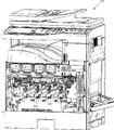
図1は、本発明の実施形態に係る画像形成装置の構成を示す図である。 FIG. 1 is a diagram illustrating a configuration of an image forming apparatus according to an embodiment of the present invention.
画像形成装置100は、外部から伝達された画像データに応じて、所定のシート(記録用紙)に対して多色および単色の画像を形成するもので、画像形成部110と自動原稿処理装置120とから構成されている。画像形成装置100は、本発明の装置本体に相当する。画像形成部110は、露光ユニット1、現像ユニット2、感光体ドラム3、クリーナユニット4、帯電器5、中間転写ベルト6、定着ユニット7、給紙カセット81および排紙トレイ91から構成されている。
The
画像形成部110の上部には、原稿が載置される透明ガラスからなる原稿載置台92が設けられる。原稿載置台92の上側には自動原稿処理装置120が取り付けられている。原稿載置台92の下側には原稿の画像を読み取る画像読取ユニット90が備えられている。自動原稿処理装置120は、原稿載置台92の上に自動で原稿を搬送する。また、自動原稿処理装置120は、矢印M方向に回動自在に構成され、原稿載置台92の上を開放することにより原稿を手置きで置くことができるようになっている。
A document placement table 92 made of transparent glass on which a document is placed is provided on the upper portion of the
画像形成装置100において扱われる画像データは、ブラック(K)、シアン(C)、マゼンタ(M),イエロー(Y)の各色を用いたカラー画像に応じたものである。したがって、現像ユニット2、感光体ドラム3、帯電器5およびクリーナユニット4は、各色に応じた4種類の潜像を形成するようにそれぞれ4個ずつ設けられ、それぞれブラック、シアン、マゼンタ、イエローに設定され、これらによって4つの画像ステーションが構成されている。
Image data handled in the
帯電器5は、感光体ドラム3の表面を所定の電位に均一に帯電させるための帯電手段であり、図1に示すようなチャージャ型の他、接触型のローラ型やブラシ型の帯電器が用いられることもある。
The charger 5 is a charging means for uniformly charging the surface of the
露光ユニット1は、レーザ射出部および反射ミラー等を備えたレーザスキャニングユニット(LSU)として構成される。露光ユニット1は、レーザビームを走査するポリゴンミラーと、ポリゴンミラーによって反射されたレーザ光を感光体ドラムに導くためのレンズやミラー等の光学要素が配置されている。露光ユニット1としては、発光素子をアレイ状にならべた例えばELやLED書込ヘッドを用いる手法も採用できる。 The exposure unit 1 is configured as a laser scanning unit (LSU) provided with a laser emitting portion, a reflection mirror, and the like. The exposure unit 1 is provided with a polygon mirror that scans the laser beam and optical elements such as a lens and a mirror for guiding the laser beam reflected by the polygon mirror to the photosensitive drum. As the exposure unit 1, for example, a method using an EL or LED writing head in which light emitting elements are arranged in an array can be employed.
露光ユニット1は、帯電された感光体ドラム3を入力された画像データに応じて露光することにより、その表面に、画像データに応じた静電潜像を形成する機能を有する。現像ユニット2はそれぞれの感光体ドラム3上に形成された静電潜像を4色(YMCK)のトナーにより顕像化するものである。また、クリーナユニット4は、現像・画像転写後における感光体ドラム3上の表面に残留したトナーを、除去・回収する。
The exposure unit 1 has a function of forming an electrostatic latent image corresponding to the image data on the surface thereof by exposing the charged
感光体ドラム3の上方に配置されている中間転写ベルトユニット6は、中間転写ベルト61、中間転写ベルト駆動ローラ62、中間転写ベルト従動ローラ63、中間転写ローラ64および中間転写ベルトクリーニングユニット65を備えている。中間転写ローラ64は、YMCK用の各色に応じて4本設けられている。
The intermediate transfer belt unit 6 disposed above the
中間転写ベルト駆動ローラ62、中間転写ベルト従動ローラ63および中間転写ローラ64は、中間転写ベルト61を張架して回転駆動させる。また中間転写ローラ64は、感光体ドラム3のトナー像を、中間転写ベルト61上に転写するための転写バイアスを与える。
The intermediate transfer
中間転写ベルト61は、各感光体ドラム3に接触するように設けられている。そして、感光体ドラム3に形成された各色のトナー像を中間転写ベルト61に順次的に重ねて転写することによって、中間転写ベルト61上にカラーのトナー像(多色トナー像)を形成する機能を有している。中間転写ベルト61は、たとえば厚さ100μm〜150μm程度のフィルムを用いて無端状に形成されている。
The
感光体ドラム3から中間転写ベルト61へのトナー像の転写は、中間転写ベルト61の裏側に接触している中間転写ローラ64によって行われる。中間転写ローラ64には、トナー像を転写するために高電圧の転写バイアス(トナーの帯電極性(−)とは逆極性(+)の高電圧)が印加されている。中間転写ローラ64は、直径8〜10mmの金属(たとえばステンレス)軸をベースとし、その表面が導電性の弾性材により、中間転写ベルト61に対して均一に高電圧を印加することができる。本実施形態では転写電極としてローラ形状を使用しているが、それ以外にブラシなども用いることが可能である。
Transfer of the toner image from the
上述のように各感光体ドラム3上で各色相に応じて顕像化された静電像は中間転写ベルト61で積層される。このように、積層された画像情報は中間転写ベルト61の回転によって、用紙と中間転写ベルト61の接触位置に配置される転写ローラ10によって用紙上に転写される。
As described above, the electrostatic images visualized according to the respective hues on the respective
このとき、中間転写ベルト61と転写ローラ10は所定ニップで圧接されるとともに、転写ローラ10にはトナーを用紙に転写させるための電圧が印加される(トナーの帯電極性(−)とは逆極性(+)の高電圧)。さらに、転写ローラ10は上記ニップを定常的に得るために、転写ローラ10または中間転写ベルト駆動ローラ62のいずれか一方を硬質材料(金属等)とし、他方を弾性ローラ等の軟質材料(弾性ゴムローラまたは発泡性樹脂ローラ等)が用いられる。
At this time, the
また、上記のように、感光体ドラム3に接触することにより中間転写ベルト61に付着したトナーまたは転写ローラ10によって用紙上に転写が行われず中間転写ベルト61上に残存したトナーは、次工程でトナーの混色を発生させる原因となるために、中間転写ベルトクリーニングユニット65によって除去・回収されるように設定されている。中間転写ベルトクリーニングユニット65には、中間転写ベルト61に接触するたとえばクリーニング部材としてクリーニングブレードが備えられており、クリーニングブレードが接触する中間転写ベルト61は、裏側から中間転写ベルト従動ローラ63で支持されている。
Further, as described above, the toner adhering to the
給紙カセット81は、画像形成に使用するシートを蓄積しておくためのトレイであり、画像形成部110の露光ユニット1の下側に設けられている。また、手差し給紙カセット82にも画像形成に使用するシートを置くことができる。さらに、画像形成部110の上方に設けられている排紙トレイ91は、印刷済みのシートをフェイスダウンで集積するためのトレイである。
The
画像形成部110には、給紙カセット81および手差し給紙カセット82のシートを転写ローラ10や定着ユニット7を経由させて排紙トレイ91に送るための略垂直形状の用紙搬送路Sが設けられている。給紙カセット81または手差し給紙カセット82から排紙トレイ91までの用紙搬送路Sの近傍には、ピックアップローラ11a,11b、複数の搬送ローラ12a〜12d、レジストローラ13、転写ローラ10、定着ユニット7等が配置されている。
The
搬送ローラ12a〜12dは、シートの搬送を促進・補助するための小型のローラであり、用紙搬送路Sに沿って複数設けられている。また、ピックアップローラ11aは、給紙カセット81の端部近傍に備えられ、給紙カセット81からシートを1枚ずつピックアップして用紙搬送路Sに供給する。
The
レジストローラ13は、用紙搬送路Sにおいて搬送されているシートを一旦保持するものである。そして、感光体ドラム3上のトナー像の先端とシートの先端を合わせるタイミングでシートを転写ローラ10に搬送する機能を有している。
The
定着ユニット7は、ヒートローラ71および加圧ローラ72を備えている。ヒートローラ71および加圧ローラ72は、シートを挟んで回転するようになっている。また、ヒートローラ71は、温度検出器からの信号に基づいて制御部によって所定の定着温度となるように設定されており、加圧ローラ72とともにトナーをシートに熱圧着することにより、シートに転写された多色トナー像を溶融・混合・圧接し、シートに対して熱定着させる機能を有している。さらに、ヒートローラ71を外部から加熱するための外部加熱ベルト73が設けられている。
The fixing
次に、用紙搬送経路を詳細に説明する。上述のように、画像形成装置100にはあらかじめシートを収納する給紙カセット81および手差し給紙カセット82が設けられている。これらの給紙カセット81および手差し給紙カセット82からシートを給紙するために各々ピックアップローラ11a,11bが配置され、シートを1枚ずつ用紙搬送路Sに導くようになっている。
Next, the paper conveyance path will be described in detail. As described above, the
給紙カセット81および手差し給紙カセット82から搬送されるシートは用紙搬送路Sの搬送ローラ12aによってレジストローラ13まで搬送され、シートの先端と中間転写ベルト61上の画像情報の先端を整合するタイミングで転写ローラ10に搬送され、シート上に画像情報が書き込まれる。その後、シートは定着ユニット7を通過することによってシート上の未定着トナーが熱で溶融・固着され、搬送ローラ12bを経て排紙トレイ91上に排出される。
A sheet conveyed from the
上記の搬送経路は、シートに対する片面印字要求のときのものであるが、これに対して両面印字要求のときは、上記のように片面印字が終了し定着ユニット7を通過したシートの後端が最終の搬送ローラ12bで把持されたときに、搬送ローラ12bが逆転することによってシートを搬送ローラ12c,12dに導く。そしてその後レジストローラ13を経てシート裏面に印字が行われた後にシートが排紙トレイ91に排出される。
The above-mentioned conveyance path is for a single-sided printing request for a sheet. On the other hand, when a double-sided printing request is made, the trailing edge of the sheet that has finished single-sided printing and has passed through the fixing
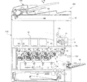
図2は、本発明の実施形態に係る画像形成装置の外枠を省略した図である。 FIG. 2 is a diagram in which the outer frame of the image forming apparatus according to the embodiment of the present invention is omitted.
画像形成装置100では、通常、転写後の感光体ドラム3にトナーが残存する。このため、画像形成装置100には、感光体ドラム3に残存したトナーを取り除くためのクリーナユニット4と、クリーナユニット4によって感光体ドラム3から取り除かれた廃トナーを収容する廃トナー容器200が備えられている。廃トナー容器200は、画像形成装置100に対して着脱可能である。
In the
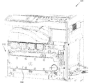
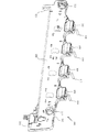
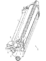
図3は、本発明の実施形態に係る画像形成装置の外枠と廃トナー容器とを省略した図である。 FIG. 3 is a diagram in which the outer frame and the waste toner container of the image forming apparatus according to the embodiment of the present invention are omitted.
廃トナー容器200の裏側には、トナー排出口210および位置決めユニット300が備えられている。トナー排出口210は、クリーナユニット4によって感光体ドラム3から取り除かれた廃トナーを廃トナー容器200に運ぶための通路である。位置決めユニット300は、感光体ドラム3を含み画像形成装置100に対して交換可能なプロセスユニット400を画像形成装置100へ位置決めするためのユニットである。
A
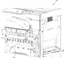
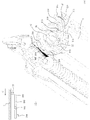
図4は、本発明の実施形態に係る画像形成装置の外枠と廃トナー容器と位置決めユニットとを省略した図である。 FIG. 4 is a diagram in which the outer frame, the waste toner container, and the positioning unit of the image forming apparatus according to the embodiment of the present invention are omitted.
位置決めユニット300の裏側には、現像ユニット2およびプロセスユニット400が備えられている。現像ユニット2およびプロセスユニット400は、画像形成装置100に対して着脱可能となっている。
On the back side of the
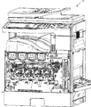
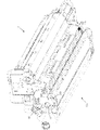
図5は、本発明の実施形態に係る画像形成装置の外枠と廃トナー容器と位置決めユニットと現像ユニットとを省略した図である。 FIG. 5 is a diagram in which the outer frame, the waste toner container, the positioning unit, and the developing unit of the image forming apparatus according to the embodiment of the present invention are omitted.
画像形成装置100は、開口路600を備えている。図5は、開口路600にプロセスユニット400を装着した状態を示す。プロセスユニット400および現像ユニット2は、開口路600に沿って着脱可能となっている。画像形成装置100には、プロセスユニット400を装着した後で現像ユニット2を装着する。
The
図6は、本発明の実施形態に係る画像形成装置の位置決めユニットを示す図である。 FIG. 6 is a diagram showing a positioning unit of the image forming apparatus according to the embodiment of the present invention.
位置決めユニット300は、表部材330と裏部材340とから構成される。また、位置決めユニット300は、操作部材311,312、回動支点部材321,322および検知スイッチ460を備えている。操作部材311,312および回動支点部材321,322は、本発明の開閉機構に相当する。検知スイッチ460は、本発明の検知機構に相当する。
The
操作部材311,312は、位置決めユニット300を画像形成装置100に固定するため又は固定解除するために作業者が回転操作するノブである。回動支点部材321,322は、画像形成装置100に回動自在に支持される支点である。位置決めユニット300は、プロセスユニット400の画像形成装置100に対する着脱時に回動支点部材321,322を支点として開閉可能である。検知スイッチ460は、位置決めユニット300がプロセスユニット400を位置決めする際に後述のプロセスユニット400に設けられている押下部410によって押下されることでプロセスユニット400が新品であることを検知することが可能である。押下部410は、本発明の作用部に相当する。すなわち、検知スイッチ460は、押下部410によって押下される部分を備え、この部分が押下されると電気的接点がオンして、プロセスユニット400が新品であることが識別される。この部分が押下されていないと、そのときに装着されているプロセスユニット400は旧品であると識別される。
The
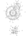
図7は、本発明の実施形態に係る画像形成装置のプロセスユニットにおける感光体ドラムの端面の図である。 FIG. 7 is a view of the end surface of the photosensitive drum in the process unit of the image forming apparatus according to the embodiment of the present invention.
図7(A)および図7(B)は、感光体ドラム3の端面をカバーするドラムカバー450を省略した図である。感光体ドラム3の端面(回転部)には、連動ギア30および回り止め32が形成されている。ドラムカバー450には、イニシャル検知ギア411およびストッパ軸446が支持されている。イニシャル検知ギア411は、本発明の新旧検知部材に相当する。感光体ドラム3には、フレーム415が取り付けられている。また、ドラム軸34は、突起状になっている。
7A and 7B are diagrams in which the
イニシャル検知ギア411は、連動ギア418を有しており、軸支部416を軸に連動ギア30と連動可能に支持されている。イニシャル検知ギア411は、押下部410および係合部412を有する。押下部410は、プロセスユニット400を画像形成装置100に装着したときに感光体ドラム3の回転に連動して不可逆的に一定の角度だけ矢印P方向に回転する。不可逆的に一定の角度だけ回転するとは、後述の被係合部414と係合部412の係合作用により、押下部410が一定の角度だけ回転した後は、逆方向に回転できないこと、および、一定の角度以上は回転しないことを意味する。フレーム415は、被係合部414を有する。係合部412は、被係合部414と一旦係合すると、イニシャル検知ギア411の連動終了の後に押下部410が検知スイッチ460に再び検知される位置まで矢印Pとは逆の方向に回転することを抑止する。また、係合部412が被係合部414と係合する位置にくると、連動ギア418と連動ギア30との噛合が解除するため、押下部410はこれ以上は回転しない。つまり、押下部410は不可逆的に一定の角度だけ矢印P方向に回転する。イニシャル検知ギア411は、プロセスユニットの新旧を識別するために用いられる。ストッパ軸446は、ストッパアーム440が感光体ドラム3の端面を押圧するように弾性力を付加してストッパアーム440を支持する。ストッパアーム440は、突起部442およびアーム444を有する。回り止め32は、ストッパアーム440との係合により感光体ドラム3の回転を抑止する。ドラム軸34は、感光体ドラム3の軸方向に突出しており、位置決めユニット300に嵌合して画像形成装置100内において正確な位置に位置決めされる。
The
また、図7は、プロセスユニット400を画像形成装置100に装着した際に位置決めユニット300が備えられる側に該当する面を表す。イニシャル検知ギア411は、プロセスユニット400を画像形成装置100に装着して位置決めユニット300を閉じると、検知スイッチ460に当接する。すなわち、プロセスユニット400を画像形成装置100に装着した状態で位置決めユニット300を開けるとイニシャル検知ギア411が露出して目視でき、イニシャル検知ギア411が新旧のいずれの状態を示しているかを容易に確認できる。
FIG. 7 shows a surface corresponding to the side on which the
図8は、本発明の実施形態に係る画像形成装置の位置決めユニットを示す図である。 FIG. 8 is a view showing a positioning unit of the image forming apparatus according to the embodiment of the present invention.
位置決めユニット300は、嵌合部36を有する。位置決めユニット300は、プロセスユニット400および現像ユニット2が画像形成装置100に装着された後で画像形成装置100に装着する。この際、感光体ドラム3のドラム軸34が位置決めユニット300の嵌合部36と嵌合するため、プロセスユニット400は正確な位置に位置決めされる。現像ユニット2はプロセスユニット400と嵌合しているため、現像ユニット2も正確な位置に位置決めされる。
The
図9は、本発明の実施形態に係る画像形成装置の現像ユニットを示す図である。 FIG. 9 is a diagram showing a developing unit of the image forming apparatus according to the embodiment of the present invention.
現像ユニット2は、側面部材20を有する。側面部材20は、プロセスユニット400と嵌合する。このように現像ユニット2がプロセスユニット400と嵌合することによって、現像ユニット2とプロセスユニット400との距離が一定に保たれ、安定して良質な画像を形成することができる。
The developing
図10は、本発明の実施形態に係る画像形成装置の現像ユニットを示す図である。 FIG. 10 is a diagram showing a developing unit of the image forming apparatus according to the embodiment of the present invention.
図10は、現像ユニット2を図9と逆の方向から見た図である。側面部材20は、ストッパ解除突起22を有する。ストッパ解除突起22は、プロセスユニット400と嵌合した際に突起部442を押下する。すると、アーム444が感光体ドラム3の端面から離間し、アーム444と回り止め32との係合が解除され、感光体ドラム3が回転可能となる。この機構については、図13および図14において説明する。
FIG. 10 is a view of the developing
図11は、本発明の実施形態に係る画像形成装置のプロセスユニットを示す図である。 FIG. 11 is a diagram showing a process unit of the image forming apparatus according to the embodiment of the present invention.
図11は、新品のプロセスユニット400を示す図である。プロセスユニット400は、ドラムカバー450が取り付けられている。ドラムカバー450は、受部420および開口部430を有する。受部420は、押下部410を破損等から保護する部材である。開口部430は、突起部442が露出する位置に設けられる。開口部430がこの位置に設けられることで、現像ユニット2とプロセスユニット400とが嵌合した際にストッパ解除突起22が突起部442を押下することができる。
FIG. 11 is a diagram showing a
図11では、イニシャル検知ギア411が感光体ドラム3の回転に連動する前の状態を表している。この状態でプロセスユニット400を画像形成装置100に装着して位置決めユニット300によって位置決めすると、押下部410が検知スイッチ460を押下するため、プロセスユニット400が新品であると画像形成装置100に識別させることができる。
FIG. 11 shows a state before the
プロセスユニット400は、プロセスユニット400の構成部品を駆動するための駆動力を受ける駆動ギアを一端に有し、駆動ギアが設けられる側と反対側にイニシャル検知ギア411を有する。この構成により、プロセスユニット400を大型化することなくイニシャル検知ギア411の設置スペースを確保することができる。
The
図12は、本発明の実施形態に係る画像形成装置のプロセスユニットを示す図である。 FIG. 12 is a diagram showing a process unit of the image forming apparatus according to the embodiment of the present invention.
図12は、旧品のプロセスユニット400を示す図である。現像ユニット2がプロセスユニット400と嵌合した際にストッパ解除突起22が開口部430から露出している突起部442を押下し、アーム444と回り止め32との係合がはずれる。すると感光体ドラム3は回転が可能となり、イニシャル検知ギア411が連動ギア30に伴って連動するため、押下部410が受部420の位置まで移動する。押下部410がこの位置まで回転すると、係合部412が被係合部414と係合するため、押下部410は検知スイッチ460に検知される位置に回転することがない。したがって、プロセスユニット400が新品であると画像形成装置100に識別されることがない。
FIG. 12 is a diagram showing an
図13は、本発明の実施形態に係る画像形成装置のプロセスユニットを示す図である。 FIG. 13 is a diagram showing a process unit of the image forming apparatus according to the embodiment of the present invention.
図13(A)は、ドラムカバー450を省略した図である。図13(A)は、新品のプロセスユニット400を示す図である。図13(B)は、アーム444と回り止め32との係合の様子を示す図である。長片状のストッパアーム440は、その中央部分がストッパ軸446で支持されていて、ストッパ軸446にはバネが内蔵されている。このバネにより、ストッパアーム440は、突起部442側が感光体ドラム3から離れるように、アーム444側が感光体ドラム3に当接するように付勢される。感光体ドラム3は、矢印N方向にのみ回転可能となっており、アーム444と回り止め32とが係合することにより感光体ドラム3の回転を抑止している。
FIG. 13A is a diagram in which the
図14は、本発明の実施形態に係るプロセスユニットを示す図である。 FIG. 14 is a diagram showing a process unit according to the embodiment of the present invention.
図14(A)は、ドラムカバー450を省略した図である。図14(A)は、旧品のプロセスユニット400を示す図である。図14(B)は、アーム444と回り止め32との係合が解除された様子を示す図である。イニシャル検知ギア411は、連動ギア418を有する。プロセスユニット400が新品のときには、連動ギア418は、連動ギア30と噛合している。ストッパ解除突起22が突起部442を押下すると、アーム444が感光体ドラム3から離れるため、アーム444と回り止め32との係合が解除され、感光体ドラム3が回転可能となる。したがって、アーム444と回り止め32との係合が解除されると、イニシャル検知ギア411は、感光体ドラム3の回転に伴って矢印P方向に連動する。なお、感光体ドラム3が回転すると回り止め32も回転するが、図14(B)に示すようにストッパ軸446は感光体ドラム3から離間して配置されているため、回り止め32の回転を妨げる部材はない。イニシャル検知ギア411が所定位置以上に連動すると、係合部412が被係合部414と係合するため、矢印P方向と逆方向へは回転しなくなる。これにより、押下部410は図示の位置で固定され、旧品として認識されることになる。
FIG. 14A is a diagram in which the
図15は、本発明の実施形態に係る画像形成装置のプロセスユニットに現像ユニットが嵌合している図である。 FIG. 15 is a diagram in which the developing unit is fitted to the process unit of the image forming apparatus according to the embodiment of the present invention.
側面部材20とドラムカバー450とが嵌合すると、プロセスユニット400と現像ユニット2との位置が一通りに決まる。したがって、画像形成装置100に取り付けた場合にぐらつかないため、良質な画像を形成できる。また、プロセスユニット400および現像ユニット2を画像形成装置100に装着する際、プロセスユニット400を装着した後に現像ユニット2を取り付ける。この順に装着することにより、プロセスユニット400の装着作業中に誤ってイニシャル検知ギア411が連動することがない。
When the
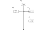
図16は、本発明の実施形態に係る画像形成装置の要部のブロック図を示す図である。このブロック図は本発明に関連している部分のみを示している。 FIG. 16 is a block diagram of a main part of the image forming apparatus according to the embodiment of the present invention. This block diagram shows only the part relevant to the present invention.
CPU500は、検知スイッチ460、カウンタ510および表示部520と接続している。検知スイッチ460は、押下部410に押下されるとオン信号を生成する。カウンタ510は、新品のプロセスユニット400が装着されたあとに印刷した用紙のサイズや枚数を計測する。表示部520は、画像形成装置100の各種情報を表示する。
検知スイッチ460が押下部410に押下されると、その情報がCPU500に伝達され、CPU500は、カウンタ510のカウント値をリセットするように信号を伝達する。また、カウンタ510のカウント値が所定値に到達すると、その情報がCPU500に伝達され、CPU500は、表示部520にプロセスユニット400を交換する旨の表示をするよう信号を伝達する。
When the
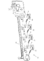
図17は、本発明の実施形態に係る画像形成装置のプロセスユニットを画像形成装置に取り付けた図である。 FIG. 17 is a diagram in which the process unit of the image forming apparatus according to the embodiment of the present invention is attached to the image forming apparatus.
図17は、未使用のプロセスユニット400を画像形成装置100に取り付けた直後の図である。また、図17は、位置決めユニット300の表部材330を省略し、検知スイッチ460を示した図である。既に説明したように、位置決めユニット300は、検知スイッチ460を有する。
FIG. 17 is a view immediately after the
プロセスユニット400および現像ユニット2を画像形成装置100に取り付ける際の手順を示す。まず、プロセスユニット400を画像形成装置100に取り付ける。次に、現像ユニット2をプロセスユニット400に嵌合させるようにして画像形成装置100に取り付ける。最後に、位置決めユニット300でプロセスユニット400および現像ユニット2を画像形成装置100に位置決め固定する。
A procedure for attaching the
位置決めユニット300でプロセスユニット400および現像ユニット2を画像形成装置100に固定すると、検知スイッチ460が押下部410に押下される。検知スイッチ460は、押下部410に押下されるとオン信号を生成し、画像形成装置100にプロセスユニット400が新品であると識別させる。
When the
図18は、本発明の実施形態に係るプロセスユニットを画像形成装置に取り付け、プロセスユニットの使用を開始したときの図である。 FIG. 18 is a diagram when the process unit according to the embodiment of the present invention is attached to the image forming apparatus and the use of the process unit is started.
プロセスユニット400の使用を開始すると、イニシャル検知ギア411が感光体ドラム3の回転に伴って連動するため、押下部410が受部420の位置まで移動する。この位置でイニシャル検知ギア411は連動終了する。この位置では、押下部410が検知スイッチ460を押下しないため、カウンタ510がリセットされることがない。また、この位置では係合部412と被係合部414とが係合してイニシャル検知ギア411が連動終了するため、プロセスユニット400を一旦取り外して再び装着しても押下部410の位置は元に戻ることがない。このため、押下部410が再び検知スイッチ460を押下することはない。したがって、プロセスユニット400を途中で何回装着し直してもカウンタ510によってプロセスユニット400の使用具合が正確にカウントされる。
When the use of the
最後に、上述の実施形態の説明は、すべての点で例示であって、制限的なものではないと考えられるべきである。本発明の範囲は、上述の実施形態ではなく、特許請求の範囲によって示される。さらに、本発明の範囲には、特許請求の範囲と均等の意味および範囲内でのすべての変更が含まれることが意図される。 Finally, the description of the above-described embodiment is to be considered in all respects as illustrative and not restrictive. The scope of the present invention is shown not by the above embodiments but by the claims. Furthermore, the scope of the present invention is intended to include all modifications within the meaning and scope equivalent to the scope of the claims.
3−感光体ドラム
30−連動ギア
100−画像形成装置
300−位置決めユニット
311,312−操作部材
321,322−回動支点部材
400−プロセスユニット
411−イニシャル検知ギア
412−係合部
414−被係合部
420−受部
460−検知スイッチ
3-Photosensitive drum 30-Interlocking gear 100-Image forming apparatus 300-
Claims (7)
前記プロセスユニットを前記画像形成装置本体に位置決めする位置決めユニットと、
を備え、
前記プロセスユニットは、前記プロセスユニットを前記画像形成装置本体に装着したときに前記感光体の回転に連動して不可逆的に一定の角度だけ回転する作用部を含み、前記作用部を前記画像形成装置本体が検出するか否かにより前記プロセスユニットが新品であるか旧品であるかを前記画像形成装置本体に識別させることが可能な新旧検知部材を有し、
前記位置決めユニットは、前記画像形成装置本体に前記プロセスユニットを位置決めする際に前記作用部によって作用されることで前記プロセスユニットが新品であることを検知することが可能な検知機構を有する画像形成装置。 A process unit having a photoconductor and replaceable in the image forming apparatus main body;
A positioning unit for positioning the process unit in the image forming apparatus main body;
With
The process unit includes an action portion that rotates irreversibly by a fixed angle in conjunction with rotation of the photosensitive member when the process unit is mounted on the image forming apparatus main body, and the action portion is included in the image forming apparatus. A new / old detection member capable of identifying the image forming apparatus main body whether the process unit is new or old depending on whether the main body detects;
The positioning unit has a detection mechanism capable of detecting that the process unit is new by being acted on by the action portion when positioning the process unit on the image forming apparatus main body. .
前記プロセスユニットは、前記係合部と係合する被係合部を有する請求項1〜4のいずれか1項に記載の画像形成装置。 The old and new detection member has an engagement part for preventing the action part from rotating to a position where the detection mechanism is pressed after the interlocking of the old and new detection member is completed,
The image forming apparatus according to claim 1, wherein the process unit includes an engaged portion that engages with the engaging portion.
前記新旧検知部材は、前記プロセスユニットを前記画像形成装置本体に装着した状態で前記位置決めユニットが閉じられると、前記検知機構に当接する請求項1〜5のいずれか1項に記載の画像形成装置。 The process unit has the old and new detection members on a surface corresponding to a side on which the positioning unit is provided when the process unit is mounted on the image forming apparatus main body.
6. The image forming apparatus according to claim 1, wherein the new / old detection member contacts the detection mechanism when the positioning unit is closed in a state where the process unit is mounted on the image forming apparatus main body. .
Priority Applications (3)
| Application Number | Priority Date | Filing Date | Title |
|---|---|---|---|
| JP2008219976A JP4731588B2 (en) | 2008-08-28 | 2008-08-28 | Image forming apparatus |
| US12/542,465 US8131164B2 (en) | 2008-08-28 | 2009-08-17 | Processing unit and image forming apparatus |
| CN 200910171338 CN101661264B (en) | 2008-08-28 | 2009-08-27 | Processing unit and image forming apparatus |
Applications Claiming Priority (1)
| Application Number | Priority Date | Filing Date | Title |
|---|---|---|---|
| JP2008219976A JP4731588B2 (en) | 2008-08-28 | 2008-08-28 | Image forming apparatus |
Publications (2)
| Publication Number | Publication Date |
|---|---|
| JP2010054822A true JP2010054822A (en) | 2010-03-11 |
| JP4731588B2 JP4731588B2 (en) | 2011-07-27 |
Family
ID=41789333
Family Applications (1)
| Application Number | Title | Priority Date | Filing Date |
|---|---|---|---|
| JP2008219976A Active JP4731588B2 (en) | 2008-08-28 | 2008-08-28 | Image forming apparatus |
Country Status (2)
| Country | Link |
|---|---|
| JP (1) | JP4731588B2 (en) |
| CN (1) | CN101661264B (en) |
Families Citing this family (1)
| Publication number | Priority date | Publication date | Assignee | Title |
|---|---|---|---|---|
| JP6091180B2 (en) * | 2012-11-21 | 2017-03-08 | キヤノン株式会社 | Image forming apparatus |
Citations (7)
| Publication number | Priority date | Publication date | Assignee | Title |
|---|---|---|---|---|
| JPH07160173A (en) * | 1993-12-07 | 1995-06-23 | Ricoh Co Ltd | Image forming device |
| JPH09258634A (en) * | 1996-03-18 | 1997-10-03 | Sharp Corp | Electrophotographic device |
| JPH103241A (en) * | 1996-06-14 | 1998-01-06 | Ricoh Co Ltd | Image forming device |
| JP2002139976A (en) * | 2000-10-30 | 2002-05-17 | Ricoh Co Ltd | Unit holding device and image forming device having the same |
| JP2003084646A (en) * | 2001-09-13 | 2003-03-19 | Canon Inc | Grip, process cartridge and apparatus for forming electrophotographic image |
| JP2004109876A (en) * | 2002-09-20 | 2004-04-08 | Ricoh Co Ltd | Image forming apparatus and latent image carrier unit mounted thereon |
| JP2007148285A (en) * | 2005-11-30 | 2007-06-14 | Brother Ind Ltd | Image forming apparatus and developing cartridge |
-
2008
- 2008-08-28 JP JP2008219976A patent/JP4731588B2/en active Active
-
2009
- 2009-08-27 CN CN 200910171338 patent/CN101661264B/en not_active Expired - Fee Related
Patent Citations (7)
| Publication number | Priority date | Publication date | Assignee | Title |
|---|---|---|---|---|
| JPH07160173A (en) * | 1993-12-07 | 1995-06-23 | Ricoh Co Ltd | Image forming device |
| JPH09258634A (en) * | 1996-03-18 | 1997-10-03 | Sharp Corp | Electrophotographic device |
| JPH103241A (en) * | 1996-06-14 | 1998-01-06 | Ricoh Co Ltd | Image forming device |
| JP2002139976A (en) * | 2000-10-30 | 2002-05-17 | Ricoh Co Ltd | Unit holding device and image forming device having the same |
| JP2003084646A (en) * | 2001-09-13 | 2003-03-19 | Canon Inc | Grip, process cartridge and apparatus for forming electrophotographic image |
| JP2004109876A (en) * | 2002-09-20 | 2004-04-08 | Ricoh Co Ltd | Image forming apparatus and latent image carrier unit mounted thereon |
| JP2007148285A (en) * | 2005-11-30 | 2007-06-14 | Brother Ind Ltd | Image forming apparatus and developing cartridge |
Also Published As
| Publication number | Publication date |
|---|---|
| CN101661264B (en) | 2012-06-13 |
| CN101661264A (en) | 2010-03-03 |
| JP4731588B2 (en) | 2011-07-27 |
Similar Documents
| Publication | Publication Date | Title |
|---|---|---|
| US8131164B2 (en) | Processing unit and image forming apparatus | |
| JP4882497B2 (en) | Image forming apparatus | |
| JP5263773B2 (en) | Color image forming apparatus | |
| JP4503066B2 (en) | Image forming apparatus | |
| JP4560571B2 (en) | Image forming apparatus with transfer belt cleaning function | |
| JP4604104B2 (en) | Image forming apparatus | |
| JP5339750B2 (en) | Image forming apparatus | |
| US8055145B2 (en) | Image forming apparatus | |
| US7672600B2 (en) | Image forming apparatus, subunit replacing method, and maintenance method of an image forming apparatus | |
| JP2009204831A (en) | Image forming apparatus | |
| JP2012053361A (en) | Image forming device and image forming method | |
| JP4722170B2 (en) | Process unit and image forming apparatus | |
| EP1542089A2 (en) | Image forming apparatus and toner supply method | |
| JP4731588B2 (en) | Image forming apparatus | |
| JP5130330B2 (en) | Image forming apparatus | |
| US9395678B2 (en) | Waste toner container and image forming apparatus | |
| JP2010175840A (en) | Image forming apparatus | |
| JP5248402B2 (en) | Transfer device and image forming apparatus provided with the transfer device | |
| JP2013104948A (en) | Image forming apparatus, method, system, and printer driver | |
| JP2011085815A (en) | Image forming apparatus | |
| JP2013097289A (en) | Image forming apparatus, method, system, and printer driver | |
| JP7263903B2 (en) | image forming device | |
| JP5089623B2 (en) | Image forming apparatus | |
| JP4654630B2 (en) | Image forming apparatus | |
| JP5833881B2 (en) | Image forming apparatus, method, system, and printer driver |
Legal Events
| Date | Code | Title | Description |
|---|---|---|---|
| A977 | Report on retrieval |
Free format text: JAPANESE INTERMEDIATE CODE: A971007 Effective date: 20100611 |
|
| A131 | Notification of reasons for refusal |
Free format text: JAPANESE INTERMEDIATE CODE: A131 Effective date: 20100615 |
|
| A521 | Written amendment |
Free format text: JAPANESE INTERMEDIATE CODE: A523 Effective date: 20100729 |
|
| A131 | Notification of reasons for refusal |
Free format text: JAPANESE INTERMEDIATE CODE: A131 Effective date: 20101109 |
|
| A521 | Written amendment |
Free format text: JAPANESE INTERMEDIATE CODE: A523 Effective date: 20110111 |
|
| TRDD | Decision of grant or rejection written | ||
| A01 | Written decision to grant a patent or to grant a registration (utility model) |
Free format text: JAPANESE INTERMEDIATE CODE: A01 Effective date: 20110322 |
|
| A61 | First payment of annual fees (during grant procedure) |
Free format text: JAPANESE INTERMEDIATE CODE: A61 Effective date: 20110419 |
|
| FPAY | Renewal fee payment (event date is renewal date of database) |
Free format text: PAYMENT UNTIL: 20140428 Year of fee payment: 3 |
|
| R150 | Certificate of patent or registration of utility model |
Ref document number: 4731588 Country of ref document: JP Free format text: JAPANESE INTERMEDIATE CODE: R150 Free format text: JAPANESE INTERMEDIATE CODE: R150 |