JP2010054198A - Reagent preparing apparatus, sample processing apparatus, and reagent preparing method - Google Patents
Reagent preparing apparatus, sample processing apparatus, and reagent preparing method Download PDFInfo
- Publication number
- JP2010054198A JP2010054198A JP2008216067A JP2008216067A JP2010054198A JP 2010054198 A JP2010054198 A JP 2010054198A JP 2008216067 A JP2008216067 A JP 2008216067A JP 2008216067 A JP2008216067 A JP 2008216067A JP 2010054198 A JP2010054198 A JP 2010054198A
- Authority
- JP
- Japan
- Prior art keywords
- reagent
- liquid
- unit
- water
- high concentration
- Prior art date
- Legal status (The legal status is an assumption and is not a legal conclusion. Google has not performed a legal analysis and makes no representation as to the accuracy of the status listed.)
- Granted
Links
- 239000003153 chemical reaction reagent Substances 0.000 title claims abstract description 373
- 238000012545 processing Methods 0.000 title claims description 52
- 238000000034 method Methods 0.000 title claims description 11
- 239000007788 liquid Substances 0.000 claims abstract description 117
- 239000012895 dilution Substances 0.000 claims abstract description 67
- 238000010790 dilution Methods 0.000 claims abstract description 67
- 238000002156 mixing Methods 0.000 claims abstract description 51
- 238000007865 diluting Methods 0.000 claims abstract description 17
- 238000002360 preparation method Methods 0.000 claims description 112
- 238000012546 transfer Methods 0.000 claims description 56
- 238000003860 storage Methods 0.000 claims description 44
- 238000011002 quantification Methods 0.000 claims description 39
- 238000001514 detection method Methods 0.000 claims description 19
- 230000000704 physical effect Effects 0.000 claims description 9
- XLYOFNOQVPJJNP-UHFFFAOYSA-N water Substances O XLYOFNOQVPJJNP-UHFFFAOYSA-N 0.000 abstract description 153
- 238000001223 reverse osmosis Methods 0.000 abstract description 146
- 239000000243 solution Substances 0.000 abstract description 3
- 239000012491 analyte Substances 0.000 abstract 1
- 238000005259 measurement Methods 0.000 description 60
- 239000000523 sample Substances 0.000 description 43
- 210000004369 blood Anatomy 0.000 description 19
- 239000008280 blood Substances 0.000 description 19
- 230000006870 function Effects 0.000 description 15
- 210000004027 cell Anatomy 0.000 description 12
- 238000004590 computer program Methods 0.000 description 12
- 239000012528 membrane Substances 0.000 description 10
- 238000003756 stirring Methods 0.000 description 10
- 210000000601 blood cell Anatomy 0.000 description 7
- 210000001772 blood platelet Anatomy 0.000 description 6
- 238000004891 communication Methods 0.000 description 6
- 210000000265 leukocyte Anatomy 0.000 description 6
- 210000001995 reticulocyte Anatomy 0.000 description 6
- 238000010586 diagram Methods 0.000 description 5
- 239000002245 particle Substances 0.000 description 5
- 238000005070 sampling Methods 0.000 description 5
- 239000008399 tap water Substances 0.000 description 5
- 235000020679 tap water Nutrition 0.000 description 5
- 238000004364 calculation method Methods 0.000 description 4
- 238000006243 chemical reaction Methods 0.000 description 4
- 238000012207 quantitative assay Methods 0.000 description 4
- 238000004519 manufacturing process Methods 0.000 description 3
- 239000011259 mixed solution Substances 0.000 description 3
- 239000000203 mixture Substances 0.000 description 3
- 238000004458 analytical method Methods 0.000 description 2
- 238000004159 blood analysis Methods 0.000 description 2
- 239000012470 diluted sample Substances 0.000 description 2
- 238000000684 flow cytometry Methods 0.000 description 2
- 239000012535 impurity Substances 0.000 description 2
- 238000012986 modification Methods 0.000 description 2
- 230000004048 modification Effects 0.000 description 2
- 230000003287 optical effect Effects 0.000 description 2
- 229920002943 EPDM rubber Polymers 0.000 description 1
- 230000005856 abnormality Effects 0.000 description 1
- 239000013584 assay control Substances 0.000 description 1
- 238000009534 blood test Methods 0.000 description 1
- 238000011109 contamination Methods 0.000 description 1
- 238000012937 correction Methods 0.000 description 1
- 230000000694 effects Effects 0.000 description 1
- 229920001971 elastomer Polymers 0.000 description 1
- 210000003743 erythrocyte Anatomy 0.000 description 1
- 238000002474 experimental method Methods 0.000 description 1
- 238000003018 immunoassay Methods 0.000 description 1
- 239000000463 material Substances 0.000 description 1
- 239000012466 permeate Substances 0.000 description 1
- 238000010186 staining Methods 0.000 description 1
- 239000012192 staining solution Substances 0.000 description 1
Images


Classifications
-
- G—PHYSICS
- G05—CONTROLLING; REGULATING
- G05D—SYSTEMS FOR CONTROLLING OR REGULATING NON-ELECTRIC VARIABLES
- G05D11/00—Control of flow ratio
- G05D11/02—Controlling ratio of two or more flows of fluid or fluent material
- G05D11/13—Controlling ratio of two or more flows of fluid or fluent material characterised by the use of electric means
- G05D11/135—Controlling ratio of two or more flows of fluid or fluent material characterised by the use of electric means by sensing at least one property of the mixture
- G05D11/136—Controlling ratio of two or more flows of fluid or fluent material characterised by the use of electric means by sensing at least one property of the mixture by sensing the viscosity
-
- B—PERFORMING OPERATIONS; TRANSPORTING
- B01—PHYSICAL OR CHEMICAL PROCESSES OR APPARATUS IN GENERAL
- B01F—MIXING, e.g. DISSOLVING, EMULSIFYING OR DISPERSING
- B01F23/00—Mixing according to the phases to be mixed, e.g. dispersing or emulsifying
- B01F23/40—Mixing liquids with liquids; Emulsifying
- B01F23/49—Mixing systems, i.e. flow charts or diagrams
-
- B—PERFORMING OPERATIONS; TRANSPORTING
- B01—PHYSICAL OR CHEMICAL PROCESSES OR APPARATUS IN GENERAL
- B01F—MIXING, e.g. DISSOLVING, EMULSIFYING OR DISPERSING
- B01F33/00—Other mixers; Mixing plants; Combinations of mixers
- B01F33/80—Mixing plants; Combinations of mixers
- B01F33/81—Combinations of similar mixers, e.g. with rotary stirring devices in two or more receptacles
- B01F33/812—Combinations of similar mixers, e.g. with rotary stirring devices in two or more receptacles in two or more alternative mixing receptacles, e.g. mixing in one receptacle and dispensing from another receptacle
-
- B—PERFORMING OPERATIONS; TRANSPORTING
- B01—PHYSICAL OR CHEMICAL PROCESSES OR APPARATUS IN GENERAL
- B01F—MIXING, e.g. DISSOLVING, EMULSIFYING OR DISPERSING
- B01F35/00—Accessories for mixers; Auxiliary operations or auxiliary devices; Parts or details of general application
- B01F35/20—Measuring; Control or regulation
- B01F35/21—Measuring
- B01F35/2133—Electrical conductivity or dielectric constant of the mixture
-
- B—PERFORMING OPERATIONS; TRANSPORTING
- B01—PHYSICAL OR CHEMICAL PROCESSES OR APPARATUS IN GENERAL
- B01F—MIXING, e.g. DISSOLVING, EMULSIFYING OR DISPERSING
- B01F35/00—Accessories for mixers; Auxiliary operations or auxiliary devices; Parts or details of general application
- B01F35/80—Forming a predetermined ratio of the substances to be mixed
- B01F35/88—Forming a predetermined ratio of the substances to be mixed by feeding the materials batchwise
- B01F35/882—Forming a predetermined ratio of the substances to be mixed by feeding the materials batchwise using measuring chambers, e.g. volumetric pumps, for feeding the substances
- B01F35/8823—Forming a predetermined ratio of the substances to be mixed by feeding the materials batchwise using measuring chambers, e.g. volumetric pumps, for feeding the substances using diaphragms or bellows
-
- G—PHYSICS
- G01—MEASURING; TESTING
- G01N—INVESTIGATING OR ANALYSING MATERIALS BY DETERMINING THEIR CHEMICAL OR PHYSICAL PROPERTIES
- G01N1/00—Sampling; Preparing specimens for investigation
- G01N1/28—Preparing specimens for investigation including physical details of (bio-)chemical methods covered elsewhere, e.g. G01N33/50, C12Q
- G01N1/38—Diluting, dispersing or mixing samples
-
- G—PHYSICS
- G01—MEASURING; TESTING
- G01N—INVESTIGATING OR ANALYSING MATERIALS BY DETERMINING THEIR CHEMICAL OR PHYSICAL PROPERTIES
- G01N35/00—Automatic analysis not limited to methods or materials provided for in any single one of groups G01N1/00 - G01N33/00; Handling materials therefor
- G01N35/10—Devices for transferring samples or any liquids to, in, or from, the analysis apparatus, e.g. suction devices, injection devices
- G01N2035/1027—General features of the devices
- G01N2035/1032—Dilution or aliquotting
Landscapes
- Chemical & Material Sciences (AREA)
- Chemical Kinetics & Catalysis (AREA)
- Physics & Mathematics (AREA)
- General Physics & Mathematics (AREA)
- Life Sciences & Earth Sciences (AREA)
- Analytical Chemistry (AREA)
- Biochemistry (AREA)
- General Health & Medical Sciences (AREA)
- Health & Medical Sciences (AREA)
- Immunology (AREA)
- Pathology (AREA)
- Engineering & Computer Science (AREA)
- Automation & Control Theory (AREA)
- Automatic Analysis And Handling Materials Therefor (AREA)
- Sampling And Sample Adjustment (AREA)
- Investigating Or Analysing Biological Materials (AREA)
- Investigating Or Analysing Materials By Optical Means (AREA)
Abstract
Description
本発明は、試薬調製装置、検体処理装置および試薬調製方法に関し、特に、希釈用液体を用いて高濃度試薬を希釈することにより試薬を調製する試薬調製装置、検体処理装置および試薬調製方法に関する。 The present invention relates to a reagent preparation device, a sample processing device, and a reagent preparation method, and more particularly to a reagent preparation device, a sample processing device, and a reagent preparation method for preparing a reagent by diluting a high concentration reagent using a dilution liquid.
従来、希釈用液体を用いて高濃度試薬を希釈することにより試薬を調製する試薬調製装置が知られている(たとえば、特許文献1および2参照)。 Conventionally, a reagent preparation device that prepares a reagent by diluting a high-concentration reagent using a dilution liquid is known (see, for example, Patent Documents 1 and 2).
上記特許文献1には、濃縮液(高濃度試薬)を定量するための計量管と、純水(希釈用液体)を定量するための計量タンクとを備えた試薬調製装置が開示されている。この試薬調製装置は、計量管により定量された濃縮液および計量タンクにより定量された純水を攪拌することにより試薬を調製するように構成されている。 Patent Document 1 discloses a reagent preparation device including a measuring tube for quantifying a concentrated liquid (high concentration reagent) and a measuring tank for quantifying pure water (dilution liquid). This reagent preparation device is configured to prepare a reagent by stirring a concentrated solution quantified by a measuring tube and pure water quantified by a measuring tank.
上記特許文献2には、高濃度試薬を定量するための試薬定量タンクと、純水(希釈用液体)を定量するための純水定量タンクと、試薬調製タンクと、純水を微量づつ試薬調製タンクに供給する定量ポンプとを備えた試薬調製装置が開示されている。この試薬調製装置は、試薬定量タンクにより定量された高濃度試薬、および、純水定量タンクにより高濃度試薬を所望濃度に希釈するよりも少ない量に定量された純水を試薬調製タンクに供給した後、定量ポンプにより純水を微量づつ試薬調製タンクに供給することにより、試薬調製タンク内の試薬を所望濃度に近づけるように構成されている。これにより、精度よく高濃度試薬を所望濃度に希釈することが可能である。
しかしながら、上記特許文献1の試薬調製装置では、濃縮液が計量管により定量され、純水が計量管とは異なる計量タンクにより定量されるので、計量管および計量タンクのそれぞれに生じる組み立て誤差などによる定量誤差によって、精度よく濃縮液を所望濃度に希釈することができないという問題点がある。 However, in the reagent preparation apparatus of Patent Document 1, the concentrated liquid is quantified by a measuring tube, and the pure water is quantified by a measuring tank different from the measuring tube. There is a problem that due to the quantitative error, the concentrated solution cannot be diluted to a desired concentration with high accuracy.
また、上記特許文献2の試薬調製装置では、定量ポンプにより純水を微量づつ試薬調製タンクに供給することによって試薬を所望濃度に近づけるので、精度よく高濃度試薬を所望濃度に希釈することが可能である一方、試薬調製タンク内の試薬が所望濃度に達するまで、定量ポンプにより純水を微量づつ繰り返し試薬調製タンクに供給し続ける必要があるので、試薬の調製動作が複雑化する。このため、より簡単な動作で、精度よく高濃度試薬を所望濃度に希釈することが可能な試薬調製装置が望まれる。
Further, in the reagent preparation device of
この発明は、上記のような課題を解決するためになされたものであり、この発明の1つの目的は、より簡単な動作で、精度よく高濃度試薬を所望濃度に希釈することが可能な試薬調製装置、検体処理装置および試薬調製方法を提供することである。 The present invention has been made to solve the above-mentioned problems, and one object of the present invention is a reagent capable of diluting a high-concentration reagent to a desired concentration with a simple operation and with high accuracy. A preparation device, a specimen processing device, and a reagent preparation method are provided.
上記目的を達成するために、この発明の第1の局面における試薬調製装置は、希釈用液体を用いて高濃度試薬を希釈することにより、検体を処理するための試薬を調製する試薬調製装置であって、高濃度試薬および希釈用液体のそれぞれの定量に共用される定量器を含み、定量器を用いて、高濃度試薬および希釈用液体のそれぞれの定量を行う液体定量部と、液体定量部により定量された高濃度試薬および希釈用液体を収容する収容部とを備える。 In order to achieve the above object, the reagent preparing device according to the first aspect of the present invention is a reagent preparing device that prepares a reagent for processing a sample by diluting a high concentration reagent with a diluting liquid. A liquid quantification unit including a quantifier commonly used for quantifying each of the high concentration reagent and the dilution liquid, and using the quantifier, each of the high concentration reagent and the dilution liquid is quantified, and a liquid quantification unit And a storage unit that stores the high-concentration reagent and the dilution liquid that are quantified by the above.
この発明の第1の局面による試薬調製装置では、上記のように、高濃度試薬および希釈用液体のそれぞれの定量に共用される定量器を液体定量部に設けるとともに、その定量器を用いて高濃度試薬および希釈用液体のそれぞれの定量を行うことによって、定量器に組み立て誤差などによる定量誤差が生じた場合でも、高濃度試薬および希釈用液体の両方が共通の定量器により定量されるので、高濃度試薬を精度よく所望の希釈倍率に希釈することができる。また、定量ポンプにより希釈用液体を微量づつ繰り返し定量するなど、複雑な試薬の調製動作を行う必要がない。その結果、より簡単な動作で、精度よく高濃度試薬を所望濃度に希釈することができる。 In the reagent preparing device according to the first aspect of the present invention, as described above, a quantifier shared for quantifying each of the high concentration reagent and the dilution liquid is provided in the liquid quantification unit, and the quantifier is used to By quantifying the concentration reagent and the dilution liquid, even if a quantification error due to assembly errors occurs in the quantifier, both the high-concentration reagent and the dilution liquid are quantified by a common quantifier. A high concentration reagent can be accurately diluted to a desired dilution factor. In addition, it is not necessary to perform complicated reagent preparation operations, such as repeatedly quantifying the dilution liquid with a metering pump. As a result, it is possible to dilute the high concentration reagent to a desired concentration with high accuracy by a simpler operation.
上記第1の局面による試薬調製装置において、好ましくは、定量器は、1回の定量動作で予め定められた一定量の液体を定量するように構成されている。このように1回の定量動作で定量される液量が予め定められていれば、シリンジポンプを用いる場合などと異なり、1回の定量動作で定量される液量を調整する必要がなく、定量動作の回数を制御するだけで高濃度試薬を所望濃度に希釈することができる。その結果、さらに簡単な動作で、高濃度試薬を所望濃度に希釈することができる。 In the reagent preparation device according to the first aspect, preferably, the quantifier is configured to quantitate a predetermined amount of liquid in a single quantification operation. In this way, if the amount of liquid quantified in one quantification operation is determined in advance, unlike the case where a syringe pump is used, it is not necessary to adjust the amount of liquid quantified in one quantification operation. A high concentration reagent can be diluted to a desired concentration simply by controlling the number of operations. As a result, the high-concentration reagent can be diluted to a desired concentration with a simpler operation.
上記第1の局面による試薬調製装置において、好ましくは、定量器はダイアフラムポンプであり、液体定量部はダイアフラムポンプを駆動するための空圧部を含む。このように構成すれば、空圧部によりダイアフラムポンプを駆動することによって、容易に、高濃度試薬および希釈用液体を定量することができる。 In the reagent preparing device according to the first aspect, preferably, the quantification device is a diaphragm pump, and the liquid quantification unit includes an air pressure unit for driving the diaphragm pump. If comprised in this way, a high concentration reagent and the liquid for dilution can be quantified easily by driving a diaphragm pump by a pneumatic part.
上記第1の局面による試薬調製装置において、好ましくは、液体定量部の動作を制御する定量制御部をさらに備える。このように構成すれば、定量制御部により、高濃度試薬が所望濃度に希釈されるように液体定量部による定量動作を制御することができる。 The reagent preparation device according to the first aspect preferably further includes a quantitative control unit that controls the operation of the liquid quantitative unit. If comprised in this way, the fixed_quantity | quantitative_assay operation | movement by a liquid fixed_quantity | quantitative_assay part can be controlled by a fixed_quantity | quantitative_assay control part so that a high concentration reagent may be diluted to a desired density | concentration.
この場合、好ましくは、定量制御部は、試薬を調製する際、高濃度試薬が収容部に移送される前に、希釈用液体が収容部に移送されるように液体定量部の動作を制御するように構成されている。このように構成すれば、希釈用液体が収容された状態の収容部に、高濃度試薬が移送されるので、高濃度試薬による収容部内の汚染を抑制することができるとともに、効率よく高濃度試薬と希釈用液体とを混合することができる。 In this case, preferably, when preparing the reagent, the quantitative control unit controls the operation of the liquid quantitative unit so that the dilution liquid is transferred to the storage unit before the high concentration reagent is transferred to the storage unit. It is configured as follows. If comprised in this way, since a high concentration reagent is transferred to the accommodating part in the state where the dilution liquid was accommodated, contamination in the accommodating part due to the high concentration reagent can be suppressed, and the high concentration reagent can be efficiently used. And the diluting liquid can be mixed.
上記定量制御部を備える構成において、好ましくは、定量制御部は、試薬を調製する際、高濃度試薬が収容部に移送された後に、希釈用液体が収容部に移送されるように液体定量部の動作を制御するように構成されている。このように構成すれば、高濃度試薬と希釈用液体との混合を効率的に行うことができる。 In the configuration including the quantitative control unit, the quantitative control unit is preferably configured so that, when preparing the reagent, after the high-concentration reagent is transferred to the storage unit, the dilution liquid is transferred to the storage unit. It is comprised so that operation | movement may be controlled. If comprised in this way, mixing with a high concentration reagent and the liquid for dilution can be performed efficiently.
上記第1の局面による試薬調製装置において、好ましくは、液体定量部は定量器から収容部に液体を移送するための移送流路を含み、高濃度試薬および希釈用液体は、移送流路を介して定量器から収容部に移送される。このように構成すれば、移送流路に残留する高濃度試薬を、その後に移送される希釈用液体とともに収容部に移送することができるので、定量された高濃度試薬が移送流路に残留するのを抑制することができ、その結果、精度よく高濃度試薬を所望濃度に希釈することができる。また、高濃度試薬を所望濃度に希釈した後、高濃度試薬が移送流路に残留するのが抑制されるので、次に高濃度試薬を希釈する際にも、精度よく希釈することができる。 In the reagent preparing device according to the first aspect, preferably, the liquid quantification unit includes a transfer channel for transferring the liquid from the quantifier to the storage unit, and the high-concentration reagent and the dilution liquid are passed through the transfer channel. Then, it is transferred from the meter to the container. If comprised in this way, since the high concentration reagent remaining in a transfer flow path can be transferred to an accommodating part with the dilution liquid transferred after that, the fixed high concentration reagent remains in a transfer flow path. As a result, it is possible to dilute a high concentration reagent to a desired concentration with high accuracy. Further, since the high-concentration reagent is suppressed from remaining in the transfer channel after the high-concentration reagent is diluted to a desired concentration, it can be diluted with high accuracy when the high-concentration reagent is diluted next time.
この場合、好ましくは、液体定量部は、上記移送流路に接続され、高濃度試薬を上記移送流路を介して定量器に移送するための第2移送流路と、第2移送流路上の上記移送流路近傍に配置され、高濃度試薬を上記移送流路に供給するためのバルブとを含む。このように構成すれば、第2移送流路のバルブと上記移送流路との間に残留される高濃度試薬の液量を低減することができる。 In this case, preferably, the liquid quantification unit is connected to the transfer channel, and a second transfer channel for transferring the high concentration reagent to the quantifier through the transfer channel, and the second transfer channel on the second transfer channel. A valve disposed in the vicinity of the transfer channel and for supplying a high concentration reagent to the transfer channel. If comprised in this way, the liquid quantity of the high concentration reagent remaining between the valve | bulb of a 2nd transfer flow path and the said transfer flow path can be reduced.
上記第1の局面による試薬調製装置において、好ましくは、収容部に収容された試薬の濃度に関する物性を示す値を検出する物性検出部と、物性検出部で検出された検出値が所定範囲にあるか否かを判定する判定手段と、検出値が所定範囲にない場合に、収容部に収容された試薬を廃棄する廃棄手段とをさらに備える。このように構成すれば、濃度が所定範囲内にない試薬(検出値が所定範囲内にない試薬)が、検体を処理するための試薬として用いられるのを防止することができる。 In the reagent preparation device according to the first aspect, preferably, a physical property detection unit that detects a value indicating a physical property related to the concentration of the reagent stored in the storage unit, and a detection value detected by the physical property detection unit are within a predetermined range. Determination means for determining whether or not the detection value is not within a predetermined range, and discarding means for discarding the reagent stored in the storage unit. With this configuration, it is possible to prevent a reagent whose concentration is not within the predetermined range (a reagent whose detection value is not within the predetermined range) from being used as a reagent for processing the specimen.
上記移送流路を備える構成において、好ましくは、液体定量部により定量された高濃度試薬および希釈用液体を収容する第2収容部をさらに備え、液体定量部は、定量器から第2収容部に液体を移送するための第3移送流路を含み、定量器内の液体が収容部または第2収容部に移送されるように、上記移送流路と第3移送流路との間で液体の流路を切り替えるための流路切替部をさらに備える。このように構成すれば、流路切替部により上記移送流路と第3移送流路とを切り替えながら、収容部および第2収容部の両方を用いて高濃度試薬を希釈することができるので、迅速に、より多くの試薬を調製することができる。 In the configuration including the transfer flow path, it is preferable to further include a second storage unit that stores the high-concentration reagent and the dilution liquid quantified by the liquid quantification unit, and the liquid quantification unit is transferred from the quantifier to the second storage unit. A third transfer channel for transferring the liquid, and the liquid in the meter is transferred between the transfer channel and the third transfer channel so that the liquid in the meter is transferred to the storage unit or the second storage unit. A flow path switching unit for switching the flow path is further provided. If comprised in this way, since a high concentration reagent can be diluted using both a storage part and a 2nd storage part, switching the above-mentioned transfer flow path and the 3rd transfer flow path by a flow path switching part, More reagents can be prepared quickly.
この場合、上記移送流路は、定量器から所定位置までの区間において第3移送流路と共用される共用流路と、上記所定位置と収容部との間の第1専用流路とを含み、第3移送流路は、共用流路と、上記所定位置と第2収容部との間の第2専用流路とを含んでいてもよい。 In this case, the transfer channel includes a common channel shared with the third transfer channel in a section from the quantifier to a predetermined position, and a first dedicated channel between the predetermined position and the accommodating portion. The third transfer channel may include a common channel and a second dedicated channel between the predetermined position and the second storage unit.
この発明の第2の局面における検体処理装置は、高濃度試薬および希釈用液体のそれぞれの定量に共用される定量器を含み、定量器を用いて、高濃度試薬および希釈用液体のそれぞれの定量を行う液体定量部と、液体定量部により定量された高濃度試薬および希釈用液体を収容する収容部と、収容部に収容された試薬を用いて検体の処理を行う検体処理部とを備える。 The sample processing apparatus according to the second aspect of the present invention includes a quantifier commonly used for quantifying each of the high concentration reagent and the dilution liquid, and each of the high concentration reagent and the dilution liquid is quantified using the quantifier. A liquid quantification unit that performs the above, a storage unit that stores the high-concentration reagent and the dilution liquid quantified by the liquid quantification unit, and a sample processing unit that processes the sample using the reagent stored in the storage unit.
この発明の第2の局面による検体処理装置では、上記のように、高濃度試薬および希釈用液体のそれぞれの定量に共用される定量器を液体定量部に設けるとともに、その定量器を用いて高濃度試薬および希釈用液体のそれぞれの定量を行うことによって、定量器に組み立て誤差などによる定量誤差が生じた場合でも、高濃度試薬および希釈用液体の両方が共通の定量器により定量されるので、高濃度試薬を精度よく所望の希釈倍率に希釈することができる。また、定量ポンプにより希釈用液体を微量づつ繰り返し定量するなど、複雑な試薬の調製動作を行う必要がないので、より簡単な動作で、精度よく高濃度試薬を所望濃度に希釈することができる。その結果、精度よく所望濃度に調製された試薬を用いて、検体処理部により、精度よく検体の処理を行うことができる。 In the sample processing apparatus according to the second aspect of the present invention, as described above, a quantifier that is commonly used for quantification of each of the high-concentration reagent and the dilution liquid is provided in the liquid quantification unit, and By quantifying the concentration reagent and the dilution liquid, even if a quantification error due to assembly errors occurs in the quantifier, both the high-concentration reagent and the dilution liquid are quantified by a common quantifier. A high concentration reagent can be accurately diluted to a desired dilution factor. In addition, since it is not necessary to perform complex reagent preparation operations such as repeatedly quantifying the dilution liquid with a metering pump, it is possible to dilute the high-concentration reagent to a desired concentration with high accuracy and simpler operation. As a result, the sample processing unit can accurately process the sample using the reagent adjusted to the desired concentration with high accuracy.
この発明の第3の局面における試薬調製方法は、希釈用液体を用いて高濃度試薬を希釈することにより、検体を処理するための試薬を調製する試薬調製方法であって、高濃度試薬および希釈用液体のそれぞれの定量に共用される定量器を用いて、高濃度試薬および希釈用液体のそれぞれの定量を行う第1ステップと、第1ステップにおいて定量された高濃度試薬および希釈用液体を混合する第2ステップとを備える。 A reagent preparation method according to a third aspect of the present invention is a reagent preparation method for preparing a reagent for treating a specimen by diluting a high concentration reagent with a diluting liquid. The first step for quantifying the high-concentration reagent and the diluting liquid is mixed with the high-concentration reagent and the diluting liquid quantified in the first step, using a quantifier that is commonly used for quantifying each of the working liquid. And a second step.
この発明の第3の局面による試薬調製方法では、上記のように、高濃度試薬および希釈用液体のそれぞれの定量に共用される定量器を用いて、高濃度試薬および希釈用液体のそれぞれの定量を行う第1ステップを設けることによって、定量器に組み立て誤差などによる定量誤差が生じた場合でも、高濃度試薬および希釈用液体の両方が共通の定量器により定量されるので、高濃度試薬を精度よく所望の希釈倍率に希釈することができる。また、定量ポンプにより希釈用液体を微量づつ繰り返し定量するなど、複雑な試薬の調製動作を行う必要がない。その結果、より簡単な動作で、精度よく高濃度試薬を所望濃度に希釈することができる。 In the reagent preparation method according to the third aspect of the present invention, as described above, the quantification of each of the high concentration reagent and the dilution liquid is performed using the quantifier shared for the determination of each of the high concentration reagent and the dilution liquid. By providing the first step, the high-concentration reagent is accurately measured because both the high-concentration reagent and the dilution liquid are quantified by a common quantifier even if a quantification error due to assembly errors occurs in the quantifier. It can be diluted to a desired dilution ratio. In addition, it is not necessary to perform complicated reagent preparation operations, such as repeatedly quantifying the dilution liquid with a metering pump. As a result, it is possible to dilute the high concentration reagent to a desired concentration with high accuracy by a simpler operation.
以下、本発明の実施形態を図面に基づいて説明する。 Hereinafter, embodiments of the present invention will be described with reference to the drawings.
図1は、本発明の一実施形態による試薬調製装置の使用状態を示した斜視図である。図2〜図14は、図1に示した一実施形態による試薬調製装置の構成を説明するための図である。まず、図1〜図14を参照して、本発明の一実施形態による試薬調製装置4の構成について説明する。なお、本実施形態では、血液検査を行うための血液分析装置1の一部として、本発明による試薬調製装置4を使用する場合について説明する。 FIG. 1 is a perspective view showing a usage state of a reagent preparing device according to an embodiment of the present invention. 2-14 is a figure for demonstrating the structure of the reagent preparation apparatus by one Embodiment shown in FIG. First, with reference to FIGS. 1-14, the structure of the reagent preparation apparatus 4 by one Embodiment of this invention is demonstrated. In the present embodiment, the case where the reagent preparation device 4 according to the present invention is used as a part of the blood analyzer 1 for performing a blood test will be described.
血液分析装置1は、図1に示すように、血液の測定を行う機能を有する測定部2と、測定部2から出力された測定データを分析して分析結果を得るデータ処理部3と、検体の処理に用いられる試薬を調製する、本発明の一実施形態による試薬調製装置4とにより構成されている。測定部2は、フローサイトメトリー法により、血液中の白血球、網状赤血球および血小板の測定を行うように構成されている。なお、フローサイトメトリー法とは、測定試料を含む試料流を形成するとともに、その試料流にレーザ光を照射することによって、測定試料中の粒子(血球)が発する前方散乱光、側方散乱光および側方蛍光を検出する粒子(血球)の測定方法である。
As shown in FIG. 1, the blood analyzer 1 includes a
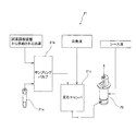
測定部2は、図2に示すように、測定試料調製部21と、測定試料の測定を行う検出部22と、検出部22の出力に対するアナログ処理部23と、表示・操作部24と、測定部2を制御するためのマイクロコンピュータ部25とを備えている。
As shown in FIG. 2, the
測定試料調製部21は、白血球測定用試料と、網状赤血球測定用試料と、血小板測定用試料とを調製するために設けられている。測定試料調製部21は、図3に示すように、血液が所定量充填されている採血管21aと、血液が吸引されるサンプリングバルブ21bと、反応チャンバ21cとを含んでいる。採血管21aは、取り替え可能であり、血液の交換を行うことが可能に構成されている。
The measurement
サンプリングバルブ21bは、吸引ピペット(図示せず)により吸引された採血管21aの血液を所定の量だけ定量する機能を有する。また、サンプリングバルブ21bは、吸引された血液に所定の試薬を混合することが可能に構成されている。つまり、サンプリングバルブ21bは、所定量の血液に試薬調製装置4から供給される所定量の試薬が混合された希釈試料を生成可能に構成されている。
The
反応チャンバ21cは、サンプリングバルブ21bから供給される希釈試料に所定の染色液をさらに混合して所定の時間反応させるように構成されている。これにより、測定試料調製部21は、白血球が染色されるとともに赤血球が溶血された、白血球測定用試料を調製する機能を有する。また、測定試料調製部21は、網状赤血球が染色された網状赤血球測定用試料を調製するとともに、血小板が染色された血小板測定用試料を調製する機能を有する。
The
また、測定試料調製部21は、白血球分類測定(以下、「DIFF測定」という)モード時に、白血球測定用試料をシース液とともに測定試料調製部21から後述するシースフローセル22c(図4参照)に供給するように構成されている。また、測定試料調製部21は、網状赤血球測定(以下、「RET測定」という)モード時に、網状赤血球測定用試料をシース液とともに測定試料調製部21からシースフローセル22cに供給するように構成されている。また、測定試料調製部21は、血小板測定(以下、「PLT測定」という)モード時に、血小板測定用試料をシース液とともに測定試料調製部21からシースフローセル22cに供給するように構成されている。
The measurement
検出部22は、図4に示すように、レーザ光を出射する発光部22aと、照射レンズユニット22bと、レーザ光が照射されるシースフローセル22cと、発光部22aから出射されるレーザ光が進む方向の延長線上に配置されている集光レンズ22d、ピンホール22eおよびPD(フォトダイオード)22fと、発光部22aから出射されるレーザ光が進む方向と交差する方向に配置されている集光レンズ22g、ダイクロイックミラー22h、光学フィルタ22i、ピンホール22jおよびAPD(アバランシェフォトダイオード)22kと、ダイクロイックミラー22hの側方に配置されているPD22lとを含んでいる。
As shown in FIG. 4, the
発光部22aは、シースフローセル22cの内部を通過する測定試料を含む試料流に対して光を出射するために設けられている。また、照射レンズユニット22bは、発光部22aから出射された光を平行光にするために設けられている。また、PD22fは、シースフローセル22cから出射された前方散乱光を受光するために設けられている。なお、シースフローセル22cから出射された前方散乱光により、測定試料中の粒子(血球)の大きさに関する情報を得ることが可能である。
The
ダイクロイックミラー22hは、シースフローセル22cから出射された側方散乱光および側方蛍光を分離するために設けられている。具体的には、ダイクロイックミラー22hは、シースフローセル22cから出射された側方散乱光をPD22lに入射させるとともに、シースフローセル22cから出射された側方蛍光をAPD22kに入射させるために設けられている。また、PD22lは、側方散乱光を受光するために設けられている。なお、シースフローセル22cから出射された側方散乱光により、測定試料中の粒子(血球)の核の大きさなどの内部情報を得ることが可能である。また、APD22kは、側方蛍光を受光するために設けられている。なお、シースフローセル22cから出射された側方蛍光により、測定試料中の粒子(血球)の染色度合いに関する情報を得ることが可能である。また、PD22f、22lおよびAPD22kは、それぞれ、受光した光信号を電気信号に変換する機能を有する。
The
アナログ処理部23は、図4に示すように、アンプ23a、23bおよび23cを含んでいる。また、アンプ23a、23bおよび23cは、それぞれ、PD22f、22lおよびAPD22kから出力された電気信号を増幅および波形処理するために設けられている。
As shown in FIG. 4, the
マイクロコンピュータ部25は、図2に示すように、制御用プロセッサおよび制御用プロセッサを動作させるためのメモリを有する制御部251と、アナログ処理部23から出力された信号をデジタル信号に変換するA/D変換部252と、A/D変換部252から出力されたデジタル信号に所定の処理を行うための演算部253とを含んでいる。
As shown in FIG. 2, the
制御部251は、バス254aおよびインターフェース255aを介して測定試料調製部21および検出部22を制御する機能を有する。また、制御部251は、バス254aおよびインターフェース255bを介して表示・操作部24と接続されるとともに、バス254bおよびインターフェース255cを介してデータ処理部3と接続されている。また、演算部253は、インターフェース255dおよびバス254aを介して制御部251に演算結果を出力する機能を有する。また、制御部251は、演算結果(測定データ)をデータ処理部3に送信する機能を有する。
The
データ処理部3は、図1に示すように、パーソナルコンピュータ(PC)などからなり、測定部2の測定データを分析するとともに、その分析結果を表示する機能を有する。また、データ処理部3は、図5に示すように、制御部31と、表示部32と、入力デバイス33とを含んでいる。
As shown in FIG. 1, the
制御部31は、測定モード情報を含む測定開始信号およびシャットダウン信号を測定部2に送信する機能を有する。また、制御部31は、図5に示すように、CPU31aと、ROM31bと、RAM31cと、ハードディスク31dと、読出装置31eと、入出力インターフェース31fと、画像出力インターフェース31gと、通信インターフェース31iとから構成されている。CPU31a、ROM31b、RAM31c、ハードディスク31d、読出装置31e、入出力インターフェース31f、画像出力インターフェース31gおよび通信インターフェース31iは、バス31hによって接続されている。
The
CPU31aは、ROM31bに記憶されているコンピュータプログラムおよびRAM31cにロードされたコンピュータプログラムを実行するために設けられている。ROM31bは、マスクROM、PROM、EPROM、EEPROMなどによって構成されており、CPU31aに実行されるコンピュータプログラムおよびこれに用いるデータなどが記録されている。
The
RAM31cは、SRAMまたはDRAMなどによって構成されている。RAM31cは、ROM31bおよびハードディスク31dに記録されているコンピュータプログラムの読み出しに用いられる。また、これらのコンピュータプログラムを実行するときに、CPU31aの作業領域として利用される。
The
ハードディスク31dは、オペレーティングシステムおよびアプリケーションプログラムなど、CPU31aに実行させるための種々のコンピュータプログラムおよびそのコンピュータプログラムの実行に用いるデータがインストールされている。後述するアプリケーションプログラム34aも、このハードディスク31dにインストールされている。
The
読出装置31eは、フレキシブルディスクドライブ、CD−ROMドライブ、またはDVD−ROMドライブなどによって構成されており、可搬型記録媒体34に記録されたコンピュータプログラムまたはデータを読み出すことができる。また、可搬型記録媒体34には、コンピュータに所定の機能を実現させるためのアプリケーションプログラム34aが格納されている。そして、データ処理部3としてのコンピュータは、その可搬型記録媒体34からアプリケーションプログラム34aを読み出し、そのアプリケーションプログラム34aをハードディスク31dにインストールするように構成されている。
The
なお、上記アプリケーションプログラム34aは、可搬型記録媒体34によって提供されるのみならず、電気通信回線(有線、無線を問わない)によってデータ処理部3と通信可能に接続された外部の機器から上記電気通信回線を通じて提供することも可能である。たとえば、上記アプリケーションプログラム34aがインターネット上のサーバコンピュータのハードディスク内に格納されており、このサーバコンピュータにデータ処理部3がアクセスして、そのアプリケーションプログラム34aをダウンロードし、これをハードディスク31dにインストールすることも可能である。
Note that the
また、ハードディスク31dには、たとえば、米マイクロソフト社が製造販売するWindows(登録商標)などのグラフィカルユーザインターフェース環境を提供するオペレーティングシステムがインストールされている。以下の説明においては、本実施形態に係るアプリケーションプログラム34aは上記オペレーティングシステム上で動作するものとしている。
The
入出力インターフェース31fは、たとえば、USB、IEEE1394、RS−232Cなどのシリアルインターフェース、SCSI、IDE、IEEE1284などのパラレルインターフェース、およびD/A変換器、A/D変換器などからなるアナログインターフェースなどから構成されている。入出力インターフェース31fには、キーボードおよびマウスからなる入力デバイス33が接続されており、ユーザがその入力デバイス33を使用することにより、データ処理部3にデータを入力することが可能である。また、入力デバイス33は、測定モードを受け付ける機能を有する。
The input /
画像出力インターフェース31gは、LCDまたはCRTなどで構成された表示部32に接続されており、CPU31aから与えられた画像データに応じた映像信号を表示部32に出力するようになっている。表示部32は、入力された映像信号にしたがって、画像(画面)を表示する。
The
ここで、本実施形態では、試薬調製装置4は、測定部2の測定試料調製部21で用いられる試薬を調製するために設けられている。具体的には、試薬調製装置4は、水道水から作製されるRO水を用いて高濃度試薬を希釈することにより、血液分析に用いられる試薬を調製するように構成されている。ここで、RO水とは、RO(Reverse Osmosis)膜(逆浸透膜)を透過することによって、不純物を取り除かれた水である。
Here, in the present embodiment, the reagent preparation device 4 is provided for preparing a reagent used in the measurement
試薬調製装置4は、図6に示すように、高濃度試薬チャンバ41と、RO水チャンバ42と、2つの混合チャンバ43および44と、ダイアフラムポンプ45と、移送チャンバ46と、供給チャンバ47と、RO水作製部48と、試薬調製装置4の各部の動作を制御する制御部49とを含んでいる。さらに、試薬調製装置4は、筐体外に設置された空圧部6(図1参照)を含み、空圧部6から供給される陰圧および陽圧を用いて、装置内における各液体の移送を行うように構成されている。空圧部6は、試薬調製装置4に対して陰圧を供給するための陰圧源61、および、陽圧を供給するための陽圧源62を有している。
As shown in FIG. 6, the reagent preparation device 4 includes a high
高濃度試薬チャンバ41は、高濃度試薬タンク5から高濃度試薬が供給されるように構成されている。高濃度試薬チャンバ41には、チャンバ内に所定量の高濃度試薬が収容されていることを検知するためのフロートスイッチ100が設けられている。また、高濃度試薬チャンバ41は、電磁バルブ200を介して高濃度試薬タンク5に接続され、電磁バルブ201を介して空圧部6の陰圧源61に接続されている。また、高濃度試薬チャンバ41は、電磁バルブ202の開閉により、大気に開放され、または、閉塞されるように構成されている。また、高濃度試薬チャンバ41は、流路300により、ダイアフラムポンプ45から混合チャンバ43および44に液体を移送するための流路301に接続されている。また、流路300上には、電磁バルブ203が設けられており、電磁バルブ203は、流路301の近傍に配置されている。具体的には、電磁バルブ203と流路301との間の流路300aの長さは、約15mmの小さい長さに設定されている。また、高濃度試薬チャンバ41に接続される流路300(300a)は、約1.8mmの内径を有しており、流路301は、約4.0mmの内径を有している。
The high
RO水チャンバ42は、高濃度試薬を希釈するためのRO水がRO水作製部48から供給されるように構成されている。RO水チャンバ42には、チャンバ内に収容されるRO水が上限量に達したこと、および、下限量に達したことをそれぞれ検知するためのフロートスイッチ101および102が設けられている。また、RO水チャンバ42は、電磁バルブ204を開放することにより、チャンバ内のRO水を廃棄可能に構成されている。また、RO水チャンバ42は、常時大気開放された状態となるように構成されている。また、RO水チャンバ42は、電磁バルブ205を介して後述するRO水作製部48のRO水貯留タンク48aに接続されている。また、RO水チャンバ42は、電磁バルブ206を介して、流路302によりダイアフラムポンプ45に接続されている。
The RO water chamber 42 is configured such that RO water for diluting the high concentration reagent is supplied from the RO water preparation unit 48. The RO water chamber 42 is provided with
混合チャンバ43および44は、高濃度試薬とRO水とを収容し、血液分析に用いられる試薬を混合するために設けられている。また、混合チャンバ43には、収容された高濃度試薬とRO水とを混合攪拌するための攪拌部43aが設けられており、攪拌部43aは、モータ43bにより駆動されるように構成されている。また、混合チャンバ43は、常時大気開放された状態となるように構成されている。また、混合チャンバ43は、電磁バルブ207を介して、流路303により流路301に接続されている。流路303は、流路301と同様に、約4mmの内径を有している。
Mixing
混合チャンバ44は、混合チャンバ43と同様に構成されており、攪拌部44aおよびモータ44bは、それぞれ、攪拌部43aおよびモータ43bに対応している。また、電磁バルブ208および流路304は、それぞれ、電磁バルブ207および流路303に対応している。なお、電磁バルブ208を閉じた状態で、電磁バルブ207を開放することによって、流路301を介して移送される液体(RO水および高濃度試薬)を混合チャンバ43に移送することが可能である。一方、電磁バルブ207を閉じた状態で、電磁バルブ208を開放すれば、流路301を介して移送される液体(RO水および高濃度試薬)を混合チャンバ43に移送することが可能である。すなわち、電磁バルブ207および208は、それぞれ、流路303および304の流路切替部として機能するように構成されている。
The mixing
ダイアフラムポンプ45は、1回の定量動作で高濃度試薬およびRO水をそれぞれ約6.0ml(一定量)分定量する機能を有している。また、ダイアフラムポンプ45は、電磁バルブ209を介して陰圧源61に接続されているとともに、電磁バルブ210を介して陽圧源62に接続されている。
The
ダイアフラムポンプ45は、図7に示すように、平面的に見て、円形形状を有している。また、ダイアフラムポンプ45は、図8および図9に示すように、EPDMなどのゴム材からなる膜体451と、膜体451を両側から挟みこむように構成された一対のケース片452および453とを含んでいる。
As shown in FIG. 7, the
膜体451は、図10に示すように、平面的に見て円形形状を有する平板状に形成されており、ネジ454を貫通させるための6つのネジ孔451aを有している。また、膜体451は、図8および図9に示すように、ケース片452および453により、両側から挟み込まれるように構成されている。
As shown in FIG. 10, the
ケース片452は、図8、図9および図11に示すように、流通口部452a(図8および図9参照)と、円錐台形状に形成された内壁部452bと、平面的に見て内壁部452bの略中央に配置された十字形状の溝部452cと、6つのネジ孔452d(図11参照)と、平面的に見て、内壁部452bを取り囲むように形成された輪形状の挟持部452eとを有している。なお、ケース片453は、図8、図9および図11に示すように、ケース片452と同様に構成されており、流通口部453a(図8および図9参照)、内壁部453b、溝部453c、ネジ孔453d(図11参照)および挟持部453eは、それぞれ、流通口部452a、内壁部452b、溝部452c、ネジ孔452dおよび挟持部452eに対応している。
As shown in FIGS. 8, 9 and 11, the
ケース片452および453は、図9に示すように、挟持部452eおよび453eで膜体451を挟み込んだ状態で、互いに6つのネジ454(図7参照)により接合されている。これにより、内壁部452bおよび膜体451により囲まれた室部452fと、内壁部453bおよび膜体451により囲まれた室部453fとが形成される。また、流通口部452aおよび室部452fは、溝部452cを介して、互いに空間的に接続されているとともに、流通口部453aおよび室部453fは、溝部453cを介して、互いに空間的に接続されている。また、室部452fおよび453fは、膜体451により、互いに空間的に隔離されている。
As shown in FIG. 9, the
また、流通口部452aは、陰圧源61および陽圧源62に接続されている。また、流通口部453aは、RO水チャンバ42に接続される流路302および混合チャンバ43(44)に液体を移送するための流路301に接続されている。ダイアフラムポンプ45は、流通口部452aに接続される陰圧源61により、室部452fに陰圧が供給されると、図12に示すように、膜体451が内壁部452bに密着されるように構成されている。これにより、膜体451により隔てられた室部453fの容積が拡大され、流通口部453aを介して室部453f内に液体(RO水、高濃度試薬またはRO水および高濃度試薬の混合液)が流入される。また、ダイアフラムポンプ45は、流通口部452aに接続される陽圧源62により、室部452fに陽圧が供給されると、図13に示すように、膜体451が内壁部453bに密着されるように構成されている。これにより、膜体451により隔てられた室部453fの容積が実質的にゼロとなるので、室部453f内の液体が流通口部453aを介して流路301に流出(押し出)される。ダイアフラムポンプ45は、この際流出される液量が約6.0mlとなるように構成されている。なお、高濃度試薬チャンバ41、RO水チャンバ42、ダイアフラムポンプ45、空圧部6、流路300〜304および電磁バルブ200〜210により、試薬調製装置4の液体定量部50(図6参照)が構成されている。
The
移送チャンバ46(図6参照)は、混合チャンバ43および44で混合された試薬を貯留するために設けられている。また、移送チャンバ46は、電磁バルブ211を介して混合チャンバ43に接続されているとともに、電磁バルブ212を介して混合チャンバ44に接続されている。また、移送チャンバ46は、電磁バルブ213を介して陰圧源61に接続されているとともに、電磁バルブ214を介して陽圧源62に接続されている。
A transfer chamber 46 (see FIG. 6) is provided for storing the reagents mixed in the mixing
供給チャンバ47は、調製された試薬を測定部2に供給するために設けられている。供給チャンバ47には、チャンバ内に収容される試薬が上限量に達したこと、および、下限量に達したことをそれぞれ検知するためのフロートスイッチ103および104が設けられている。また、供給チャンバ47は、電磁バルブ215を介して移送チャンバ46に接続されている。また、供給チャンバ47は、電磁バルブ216を介して、測定部2に接続されているとともに、電磁バルブ217を開放することにより、チャンバ内の試薬を廃棄可能に構成されている。また、供給チャンバ47は、常時大気開放された状態となるように構成されている。
The
移送チャンバ46と供給チャンバ47との間には、試薬の電気伝導度を測定するための導電率センサ400が設けられている。導電率センサ400は、導電率センサ400が配置された位置における試薬の温度を測定するための温度センサ401を含んでいる。
Between the
RO水作製部48は、高濃度試薬を希釈するための希釈用液体としてのRO水を、水道水を用いて作製することが可能なように構成されている。また、RO水作製部48は、RO水貯留タンク48aと、RO膜48bと、水道水に含まれる不純物を取り除くことによって、RO膜48bを保護するためのフィルタ48cとを含んでいる。さらに、RO水作製部48は、水分子がRO膜48bを透過するようにフィルタ48cを通過した水に高圧をかける高圧ポンプ48dと、水道水の供給を制御する電磁バルブ218とを含んでいる。
The RO water preparation unit 48 is configured so that RO water as a dilution liquid for diluting a high concentration reagent can be prepared using tap water. In addition, the RO water production unit 48 includes an RO water storage tank 48a, an
RO水貯留タンク48aは、RO膜48bを透過したRO水を貯留するために設けられている。RO水貯留タンク48aには、所定量のRO水が貯留されていることを検知するためのフロートスイッチ105が設けられている。さらに、RO水貯留タンク48aには、RO水貯留タンク48a内のRO水の電気伝導度を測定するための導電率センサ402が設けられている。導電率センサ402は、RO水の温度を測定するための温度センサ403を含んでいる。
The RO water storage tank 48a is provided to store the RO water that has passed through the
図14に示すように、制御部49は、CPU49aと、ROM49bと、RAM49cと、データ処理部3に接続される通信インターフェース49dと、各回路を介して、試薬調製装置4内の各部に接続されるI/O(Input/Output)部49eとを含んでいる。
As shown in FIG. 14, the
CPU49aは、ROM49bに記憶されているコンピュータプログラムおよびRAM49cにロードされたコンピュータプログラムを実行するために設けられている。また、CPU49aは、これらのコンピュータプログラムを実行するときに、RAM49cを作業領域として利用するように構成されている。
The
次に、試薬の電気伝導度の目標値を求める一般式を以下の式(1)に示す。 Next, a general formula for obtaining the target value of the electrical conductivity of the reagent is shown in the following formula (1).
Z0={X+(A−1)Y}/A・・・・・(1)
上記式(1)において、Z0は、高濃度試薬とRO水とが混合攪拌された試薬の25℃における電気伝導度の目標値(ms/cm)、Xは、高濃度試薬の25℃における電気伝導度(ms/cm)、Yは、RO水の25℃における電気伝導度(ms/cm)、Aは、希釈倍率(既知)(本実施形態では25倍)をそれぞれ表す。なお、Xは、高濃度試薬固有の値であり、予め実験などにより得られた既知の値である。
Z 0 = {X + (A−1) Y} / A (1)
In the above formula (1), Z 0 is a target value (ms / cm) of electric conductivity at 25 ° C. of a reagent in which a high concentration reagent and RO water are mixed and stirred, and X is a high concentration reagent at 25 ° C. Electric conductivity (ms / cm), Y represents the electric conductivity (ms / cm) of RO water at 25 ° C., and A represents the dilution factor (known) (25 times in this embodiment). X is a value unique to the high concentration reagent, and is a known value obtained in advance through experiments or the like.
また、温度センサ403により得られるRO水の温度、および、温度センサ401により得られる試薬の温度を考慮するための補正式を以下の式(2)に示す。
Further, a correction formula for considering the temperature of the RO water obtained by the
Z=[{X+(A−1)Y}/A]×{1+α1(T2−25)}=[[X+(A−1)Y1/{1+α0(T1−25)}]/A]×{1+α1(T2−25)}・・・・・(2)
上記式(2)において、Zは、高濃度試薬とRO水とが混合攪拌された試薬のT2℃における電気伝導度の目標値(ms/cm)、Y1は、RO水のT1℃における電気伝導度(ms/cm)、T1は、RO水の温度(℃)、T2は、高濃度試薬とRO水とが混合攪拌された試薬の温度(℃)、α0は、RO水の電気伝導度の25℃に対する温度係数、α1は、高濃度試薬とRO水とが混合攪拌された試薬の電気伝導度の25℃に対する温度係数をそれぞれ表す。なお、温度係数α0およびα1は、液体の種類や濃度によって異なるが、JIS(日本工業規格)では、簡易的に0.02が用いられる。
Z = [{X + (A−1) Y} / A] × {1 + α1 (T2-25)} = [[X + (A−1) Y1 / {1 + α0 (T1-25)}] / A] × {1 + α1 (T2-25)} (2)
In the above formula (2), Z is a target value (ms / cm) of electric conductivity at T2 ° C. of a reagent in which a high concentration reagent and RO water are mixed and stirred, and Y1 is electric conductivity at T1 ° C. of RO water. Degree (ms / cm), T1 is the temperature (° C.) of the RO water,
本実施形態では、CPU49aは、上記した式(2)により目標値Zを算出するように構成されている。したがって、CPU49aは、所望する希釈倍率A(既知)、RO水の電気伝導度の検出値Y1、RO水の温度の測定値T1、混合攪拌された試薬の温度の測定値T2および高濃度試薬の電気伝導度X(既知)に基づいて、目標値を決定する。
In the present embodiment, the
通信インターフェース49dは、ユーザが試薬調製装置4内で発生したエラーを確認することができるように、エラー情報をデータ処理部3に伝達可能に構成されている。エラー情報としては、高濃度試薬タンク5の交換を促すための情報、RO水が供給されなくなったことを知らせる情報、陰圧源61および陽圧源62の異常を知らせる情報などがある。これらのエラー情報に基づいて、データ処理部3の表示部32にエラー通知が表示される。
The
I/O部49eは、図14に示すように、各センサ回路を介して、フロートスイッチ100〜105、導電率センサ400、402および温度センサ401、403から信号が入力されるように構成されている。また、I/O部49eは、各駆動回路を介して、電磁バルブ200〜218、モータ43b、44bおよび高圧ポンプ48dの駆動を制御するために、各駆動回路に信号を出力するように構成されている。
As shown in FIG. 14, the I /
図15は、図1に示した一実施形態による試薬調製装置の試薬調製処理動作を説明するためのフローチャートである。次に、図6および図15を参照して、本発明の一実施形態による試薬調製装置4の試薬調製処理動作について説明する。 FIG. 15 is a flowchart for explaining the reagent preparation processing operation of the reagent preparing device according to the embodiment shown in FIG. Next, with reference to FIG. 6 and FIG. 15, the reagent preparation processing operation of the reagent preparing device 4 according to one embodiment of the present invention will be described.
まず、図15のステップS1において、CPU49aにより、ROM49bに記憶されているコンピュータプログラムの初期化が行われる。次に、ステップS2において、CPU49aにより、フロートスイッチ105の検知結果に基づいて、図6に示すRO水貯留タンク48aに所定量のRO水が収容されているか否かが判断される。所定量のRO水がRO水貯留タンク48aに貯留されていない場合には、ステップS3において、RO水作製部48によりRO水作製処理が行われる。なお、RO水は、RO水貯留タンク48aから電磁バルブ205を介してRO水チャンバ42に供給され、フロートスイッチ101によりRO水が上限量に達したことが検知されると、CPU49aにより、電磁バルブ205が閉じられて、RO水の供給が停止される。
First, in step S1 of FIG. 15, the
図16は、図15に示した試薬調製処理動作のステップS3におけるRO水作製処理動作を説明するためのフローチャートである。次に、図6および図16を参照して、図15に示した試薬調製処理動作のステップS3におけるRO水作製処理動作について説明する。 FIG. 16 is a flowchart for explaining the RO water production processing operation in step S3 of the reagent preparation processing operation shown in FIG. Next, the RO water production processing operation in step S3 of the reagent preparation processing operation shown in FIG. 15 will be described with reference to FIG. 6 and FIG.
まず、図16のステップS301において、CPU49aにより、図6に示す電磁バルブ218が開放され、水道水がフィルタ48cを通過する。次に、ステップS302において、CPU49aにより、高圧ポンプ48dが駆動され、フィルタ48cを通過した水が高圧によりRO膜48bを透過する。そして、ステップS303において、フロートスイッチ105の検知結果に基づいて、所定量のRO水がRO水貯留タンク48aに収容されているか否かが判断される。RO水が所定量に満たない場合には、この判断が繰り返され、RO水貯留タンク48aに継続してRO膜48bを透過したRO水が供給される。一方、RO水が所定量に達した場合には、ステップS304において、電磁バルブ218が閉じられるとともに、高圧ポンプ48dの駆動が停止されて、動作が終了される。
First, in step S301 of FIG. 16, the
図15のステップS2の判断において、RO水貯留タンク48aに所定量のRO水が収容されている場合には、ステップS4において、CPU49aにより、フロートスイッチ100の検知結果に基づいて、高濃度試薬チャンバ41に所定量の高濃度試薬が収容されているか否かが判断される。所定量の高濃度試薬が貯留されていない場合には、ステップS5において、高濃度試薬タンク5から高濃度試薬チャンバ41に高濃度試薬が補充される。具体的には、電磁バルブ202および203が閉じられた状態で、電磁バルブ200および201が開放されることにより、高濃度試薬が陰圧力により高濃度試薬チャンバ41に流入される。
In the determination of step S2 in FIG. 15, if a predetermined amount of RO water is stored in the RO water storage tank 48a, the high concentration reagent chamber is determined by the
所定量の高濃度試薬が高濃度試薬チャンバ41に収容されている場合には、ステップS6において、CPU49aにより、供給チャンバ47に所定量の試薬が貯留されているか否かが判断される。所定量の試薬が貯留されている場合には、ステップS14に移行される。一方、所定量の試薬が貯留されていない場合には、ステップS7において、高濃度試薬およびRO水の供給処理が行われる。
When a predetermined amount of high concentration reagent is stored in the high
図17は、図15に示した試薬調製処理動作のステップS7における高濃度試薬およびRO水の供給処理動作を説明するためのフローチャートである。次に、図6、図12、図13および図17を参照して、図15に示した試薬調製処理動作のステップS7における高濃度試薬およびRO水の供給処理動作について説明する。 FIG. 17 is a flowchart for explaining the supply processing operation of the high concentration reagent and the RO water in step S7 of the reagent preparation processing operation shown in FIG. Next, the high concentration reagent and RO water supply processing operation in step S7 of the reagent preparation processing operation shown in FIG. 15 will be described with reference to FIGS.
まず、試薬調製装置4の初期状態(試薬調製処理の直前の状態)として、図6に示す流路301〜304は、実質的にRO水により満たされているとともに、流路300は、実質的に高濃度試薬により満たされている。なお、流路300と流路301とは直接接続されているが、流路301の約4.0mmの内径に対して、流路300(300a)の内径は約1.8mmと小さいため、流路300内の高濃度試薬は、流路301内のRO水と混合され難くなっている。また、電磁バルブ203と流路301との間の流路300aは、内径が約1.8mmかつ約15mmの小さい長さに設定されているので、流路300aに存在する高濃度試薬の量は極めて少量である。
First, as an initial state of the reagent preparation device 4 (a state immediately before the reagent preparation process), the
図17のステップS701において、ダイアフラムポンプ45により、RO水チャンバ42から約6.0mlのRO水が吸引される。具体的には、電磁バルブ206および209が開放されることにより、図12に示すように、ダイアフラムポンプ45の室部452fに陰圧が供給されて、流路302を介して室部453fにRO水が流入される。次に、ステップS702において、電磁バルブ206および209が閉じられた後、電磁バルブ207および210が開放されることにより、図13に示すように、室部452fに陽圧が供給されて、室部453fからRO水が吐出される。これにより、流路301および303を介して、約6.0mlのRO水が混合チャンバ43に供給される。
In FIG. 17, about 6.0 ml of RO water is sucked from the RO water chamber 42 by the
その後、ステップS703において、ダイアフラムポンプ45により、高濃度試薬チャンバ41から約6.0mlの高濃度試薬が吸引される。具体的には、電磁バルブ207および210が閉じられた後、電磁バルブ202、203および209が開放されることにより、図12に示すように、ダイアフラムポンプ45の室部452fに陰圧が供給されて、流路300および301を介して室部453fに高濃度試薬が吸引される。詳細には、高濃度試薬チャンバ41から流出された約6.0mlの高濃度試薬が流路301に残留しているRO水と混合されることにより、室部453fには、RO水と高濃度試薬との混合液が吸引される。また、このときの流路301には、RO水と高濃度試薬との混合液が充満されている。すなわち、この状態においては、室部453fおよび流路301を合わせた領域に、高濃度試薬チャンバ41から流出された約6.0mlの高濃度試薬が存在している。なお、高濃度試薬は、流路300aにも存在するが、上述のように、流路300aに存在する高濃度試薬の量は極めて少量であるので、実質的に無視することができる。さらに、2回目の試薬調製処理動作以降の高濃度試薬の吸引時には、前回の試薬調製処理動作により流路300aに残留していた高濃度試薬が流路301側に押し出されるので、室部453fおよび流路301を合わせた領域に、より正確に約6.0mlの高濃度試薬が存在することになる。
Thereafter, in step S703, about 6.0 ml of the high concentration reagent is aspirated from the high
次に、ステップS704において、電磁バルブ203および209が閉じられた後、電磁バルブ207および210が開放されることにより、図13に示すように、室部452fに陽圧が供給されて、室部453fからRO水および高濃度試薬の混合液が吐出される。これにより、流路301および303を介して、RO水および高濃度試薬の混合液が混合チャンバ43に供給される。この際、流路301および303には、数mlの高濃度試薬がRO水と混合された状態で残留している。
Next, in step S704, after the
そして、ステップS705において、CPU49aにより、n=1に設定される。ここで、nは、ダイアフラムポンプ45によるRO水の吐出回数を表しており、1から始まる実数で定義される。次に、ステップS706において、上記ステップS701と同様に、ダイアフラムポンプ45により、RO水チャンバ42から約6.0mlのRO水が吸引される。そして、ステップS707において、上記ステップS702と同様に、ダイアフラムポンプ45の室部453fからRO水が吐出される。これにより、流路301および303に残留していた高濃度試薬が、RO水とともに混合チャンバ43に移送される。
In step S705, the
その後、ステップS708において、CPU49aにより、nが22よりも大きいか否かが判断される。nが22よりも大きくない場合には、ステップS709において、n=n+1に設定され、nが22よりも大きくなるまでステップS706〜ステップS709の動作が繰り返される。すなわち、ダイアフラムポンプ45による高濃度試薬の吸引および吐出動作1回に対して、RO水の吸引および吐出動作が24回行われるまでステップS706〜ステップS709の動作が繰り返される。そして、nが22よりも大きくなると、動作は終了される。これにより、混合チャンバ43には、約6.0ml×24回=約144mlのRO水と、約6.0ml×1回=約6.0mlの高濃度試薬とが収容される。また、ダイアフラムポンプ45による高濃度試薬の吸引および吐出動作の後、RO水の吸引および吐出動作を23回行うため、流路301および303に残留していた高濃度試薬はすべて混合チャンバ43に移送され、その結果、流路301および303には、RO水のみが存在する状態となる。
Thereafter, in step S708, the
なお、上記の動作において、電磁バルブ207に替えて、電磁バルブ208を駆動すれば、混合チャンバ44に、約144mlのRO水と約6.0mlの高濃度試薬とを移送することが可能である。
In the above operation, if the
図15のステップS7による高濃度試薬およびRO水の供給処理が行われた後、ステップS8において、混合チャンバ43(44)に収容された高濃度試薬およびRO水が攪拌部43a(44a)により混合攪拌される。そして、ステップS9において、電磁バルブ211(212)および213が開放されることにより、混合チャンバ43(44)内の試薬が移送チャンバ46に移送される。
After the supply processing of the high concentration reagent and the RO water in step S7 of FIG. 15, the high concentration reagent and the RO water accommodated in the mixing chamber 43 (44) are mixed by the stirring
次に、ステップS10において、電磁バルブ211(212)および213が閉じられた後、電磁バルブ214および215が開放されて、試薬が移送チャンバ46から供給チャンバ47に移送される。この際、ステップS11において、導電率センサ400により、電気伝導度Cが測定されるとともに、温度センサ401により試薬の温度T2が測定される。そして、ステップS12において、CPU49aにより、電気伝導度Cが所定範囲内にあるか否かが判断される。具体的には、上記式(2)により算出される、希釈倍率25倍における電気伝導度の目標値Zに対して、測定された電気伝導度Cが所定範囲内にあるか否かが判断される。電気伝導度Cが所定範囲内にない場合には、ステップS13において、電磁バルブ217が開放されることにより、供給チャンバ47内の試薬が廃棄される。これにより、精度よく希釈された試薬のみを測定部により用いることが可能となる。
Next, in Step S10, after the electromagnetic valves 211 (212) and 213 are closed, the
ステップS14において、CPU49aにより、データ処理部3を介して伝達される測定部2からの試薬供給指示があるか否かが判断され、指示がない場合には、ステップS16に移行される。試薬供給指示がある場合には、ステップS15において、電磁バルブ216が開放されることにより、供給チャンバ47内の試薬が測定部2に供給される。そして、ステップS16において、CPU49aにより、ユーザからのシャットダウン指示の有無が判断され、指示がない場合にはステップS2に移行される。シャットダウン指示がある場合には、試薬調製処理動作が終了される。
In step S14, the
本実施形態では、上記のように、高濃度試薬およびRO水のそれぞれの定量に共用されるダイアフラムポンプ45を液体定量部50に設けるとともに、そのダイアフラムポンプ45を用いて高濃度試薬およびRO水のそれぞれの定量を行うことによって、ダイアフラムポンプ45に組み立て誤差などによる定量誤差が生じた場合でも、高濃度試薬およびRO水の両方が共通のダイアフラムポンプ45により定量されるので、高濃度試薬を精度よく所望の希釈倍率に希釈することができる。また、定量ポンプによりRO水を微量づつ繰り返し定量するなど、複雑な試薬の調製動作を行う必要がないので、より簡単な動作で、精度よく高濃度試薬を所望濃度に希釈することができる。
In the present embodiment, as described above, the
また、本実施形態では、試薬を調製する際、高濃度試薬が混合チャンバ43(44)に移送される前に、RO水が混合チャンバ43(44)に移送されるように、試薬調製処理動作を制御するようにCPU49aを構成することによって、RO水が収容された状態の混合チャンバ43(44)に高濃度試薬が移送されるので、高濃度試薬による混合チャンバ43(44)内の汚染を抑制することができるとともに、効率よく高濃度試薬とRO水とを混合することができる。
In the present embodiment, when preparing the reagent, the reagent preparation processing operation is performed so that the RO water is transferred to the mixing chamber 43 (44) before the high concentration reagent is transferred to the mixing chamber 43 (44). By configuring the
また、本実施形態では、試薬を調製する際、高濃度試薬が流路301を介してダイアフラムポンプ45から混合チャンバ43(44)に移送された後、RO水が流路301を介してダイアフラムポンプ45から混合チャンバ43(44)に移送されるように、試薬調製処理動作を制御するようにCPU49aを構成することによって、流路301に残留する高濃度試薬を、その後に移送されるRO水とともに混合チャンバ43(44)に移送することができるので、ダイアフラムポンプ45により定量された高濃度試薬が流路301に残留するのを抑制することができる。その結果、精度よく高濃度試薬を所望濃度に希釈することができる。また、高濃度試薬を所望濃度に希釈した後、高濃度試薬が流路301に残留するのが抑制されるので、次に高濃度試薬を希釈する際にも、精度よく希釈することができる。
In this embodiment, when preparing the reagent, after the high concentration reagent is transferred from the
また、本実施形態では、混合チャンバ43(44)に収容された試薬の電気伝導度Cを測定する導電率センサ400と、導電率センサ400により測定された測定値が所定範囲にあるか否かを判定するCPU49aと、測定値が所定範囲にない場合に、混合チャンバ43(44)に収容された試薬を廃棄するための電磁バルブ27とを設けることによって、濃度が所定範囲内にない試薬(電気伝導度Cが所定範囲内にない試薬)が、検体を処理するための試薬として用いられるのを防止することができる。
In this embodiment, the
なお、今回開示された実施形態は、すべての点で例示であって制限的なものではないと考えられるべきである。本発明の範囲は、上記した実施形態の説明ではなく特許請求の範囲によって示され、さらに特許請求の範囲と均等の意味および範囲内でのすべての変更が含まれる。 The embodiment disclosed this time should be considered as illustrative in all points and not restrictive. The scope of the present invention is shown not by the above description of the embodiments but by the scope of claims for patent, and further includes all modifications within the meaning and scope equivalent to the scope of claims for patent.
たとえば、上記実施形態では、高濃度試薬を25倍に希釈する例を示したが、本発明はこれに限らず、高濃度試薬を25倍以外の他の倍率として、たとえば20倍に希釈するようにしてもよい。この場合、ダイアフラムポンプ45を用いて、RO水を1回定量した後、高濃度試薬を2回定量し、その後、RO水を37回定量することにより希釈倍率20倍の試薬を調製してもよい。また、ダイアフラムポンプ45を用いて希釈倍率20倍の試薬を調製する場合には、RO水を1回定量した後、高濃度試薬を1回定量し、その後、再度RO水を1回定量した後、高濃度試薬を1回定量し、その後、RO水を36回定量してもよい。このようにしてRO水と高濃度試薬を交互に混合チャンバに移送すれば、混合チャンバ内でRO水と高濃度試薬とをより効率的に混合することができる。
For example, in the above-described embodiment, an example in which a high concentration reagent is diluted 25 times has been shown. However, the present invention is not limited to this, and the high concentration reagent may be diluted other than 25 times, for example, 20 times. It may be. In this case, after quantifying the RO water once using the
また、上記実施形態では、希釈用液体としてのRO水を1回定量した後、高濃度試薬を1回定量し、その後、RO水を23回定量して希釈倍率25倍の試薬を調製する例を示したが、本発明はこれに限らず、たとえば、RO水を2回定量した後、高濃度試薬を1回定量し、その後、RO水を22回定量して希釈倍率25倍の試薬を調製してもよい。 Moreover, in the said embodiment, after quantifying RO water as a dilution liquid once, a high concentration reagent is quantified once, and then RO water is quantified 23 times to prepare a reagent with a dilution factor of 25 times. However, the present invention is not limited to this. For example, after quantifying the RO water twice, the high concentration reagent is quantified once, and then the RO water is quantified 22 times to obtain a reagent with a dilution factor of 25 times. It may be prepared.
また、上記実施形態では、希釈用液体としてのRO水を1回定量した後、高濃度試薬を1回定量し、その後、RO水を23回定量して希釈倍率25倍の試薬を調製する例を示したが、本発明はこれに限らず、たとえば、容量がダイアフラムポンプ45の半分であるダイアフラムポンプを用いて、RO水を1回定量した後、高濃度試薬を2回定量し、その後、RO水を47回定量することにより希釈倍率25倍の試薬を調製してもよい。このようにすれば、RO水および高濃度試薬の混合チャンバへの移送回数を増やすことができるため、混合チャンバ内でより効率的にRO水と高濃度試薬とを混合することができる。
Moreover, in the said embodiment, after quantifying RO water as a dilution liquid once, a high concentration reagent is quantified once, and then RO water is quantified 23 times to prepare a reagent with a dilution factor of 25 times. However, the present invention is not limited to this. For example, using a diaphragm pump whose capacity is half that of the
また、容量がダイアフラムポンプ45の半分であるダイアフラムポンプを用いて希釈倍率25倍の試薬を調製する場合には、RO水を1回定量した後、高濃度試薬を1回定量し、その後、再びRO水を1回定量した後、高濃度試薬を1回定量し、その後、RO水を46回定量してもよい。このようにすれば、RO水および高濃度試薬の混合チャンバへの移送回数を増やすことができるだけでなく、RO水と高濃度試薬を交互に混合チャンバに移送することができるため、RO水と高濃度試薬とをより効率的に混合することができる。
When preparing a reagent with a dilution factor of 25 times using a diaphragm pump whose volume is half that of the
また、上記実施形態では、定量器の一例として、ダイアフラムポンプを示したが、本発明はこれに限らず、1回の定量動作で予め定められた一定量の液体を定量可能な定量器であれば、たとえば、ピストンのストローク量が固定されたシリンジポンプであってもよい。 In the above embodiment, a diaphragm pump is shown as an example of a quantifier. However, the present invention is not limited to this, and any quantifier capable of quantifying a predetermined amount of liquid in one quantification operation. For example, a syringe pump in which the stroke amount of the piston is fixed may be used.
また、上記実施形態では、収容部としての混合チャンバと供給チャンバとの間に移送チャンバを設ける例を示したが、本発明はこれに限らず、混合チャンバと供給チャンバとの間に移送チャンバを設けずに、混合チャンバを移送チャンバとして用いてもよい。 In the above-described embodiment, an example in which a transfer chamber is provided between the mixing chamber and the supply chamber as the accommodating portion has been described. However, the present invention is not limited thereto, and the transfer chamber is provided between the mixing chamber and the supply chamber. Without being provided, the mixing chamber may be used as a transfer chamber.
また、上記実施形態では、試薬調製装置の一例として、測定部と別個に設置される試薬調製装置を示したが、本発明はこれに限らず、図18に示すように、測定部内に設けられ、試薬調製機構として機能する試薬調製装置であってもよい。このように試薬調製機構を備える測定部(装置)としては、たとえば、血球計数装置、免疫測定装置および塗抹標本作製装置などがあるが、特に、希釈用液体の使用量が多い血球計数装置に適している。 In the above embodiment, as an example of the reagent preparation device, the reagent preparation device installed separately from the measurement unit is shown. However, the present invention is not limited to this, and is provided in the measurement unit as shown in FIG. Also, a reagent preparation device that functions as a reagent preparation mechanism may be used. Examples of the measurement unit (device) having a reagent preparation mechanism include a blood cell counter, an immunoassay device, and a smear preparation device, which are particularly suitable for blood cell counters that use a large amount of dilution liquid. ing.
また、上記実施形態では、定量器の一例としてのダイアフラムポンプを1つ設ける例を示したが、本発明はこれに限らず、ダイアフラムポンプを2つ以上設けてもよい。2つ以上のダイアフラムポンプを用いて所望の希釈倍率の試薬を調製する場合、各ダイアフラムポンプに異なる定量誤差が生じていても、各ダイアフラムポンプで所望の希釈倍率の試薬をそれぞれ調製できるため、ダイアフラムポンプを複数設けた場合には、所望の希釈倍率の試薬を短時間でより多く調製することができる。 Moreover, in the said embodiment, although the example which provides one diaphragm pump as an example of a fixed_quantity | quantitative_assay was shown, this invention is not restricted to this, You may provide two or more diaphragm pumps. When two or more diaphragm pumps are used to prepare a reagent with a desired dilution ratio, each diaphragm pump can prepare a reagent with a desired dilution ratio even if a different quantitative error occurs in each diaphragm pump. When a plurality of pumps are provided, a larger number of reagents having a desired dilution ratio can be prepared in a short time.
また、上記実施形態では、収容部としての混合チャンバに攪拌部を設けて、混合チャンバ内で高濃度試薬とRO水とを混合する例を示したが、本発明はこれに限らず、混合チャンバに攪拌部を設けずに、混合チャンバから移送チャンバを介して供給チャンバに移送する間に、高濃度試薬とRO水とが自然混合されるようにしてもよい。この場合には、物性検出部としての導電率センサを、供給チャンバの直前に設けることが好ましい。 Moreover, in the said embodiment, although the stirring part was provided in the mixing chamber as an accommodating part and the high concentration reagent and RO water were mixed in a mixing chamber, the present invention was not restricted to this, A mixing chamber is shown. The high concentration reagent and the RO water may be naturally mixed during the transfer from the mixing chamber to the supply chamber via the transfer chamber without providing the stirring unit. In this case, it is preferable to provide a conductivity sensor as a physical property detection unit immediately before the supply chamber.
また、上記実施形態では、物性検出部としての導電率センサを移送チャンバと供給チャンバとの間に設ける例を示したが、本発明はこれに限らず、収容部としての混合チャンバと移送チャンバとの間に設けてもよい。なお、この場合には、電気伝導度Cが所定範囲内にない試薬を移送チャンバから廃棄するようにしてもよい。 In the above embodiment, an example in which the conductivity sensor as the physical property detection unit is provided between the transfer chamber and the supply chamber has been described. However, the present invention is not limited thereto, and the mixing chamber and the transfer chamber as the storage unit are provided. You may provide between. In this case, a reagent whose electrical conductivity C is not within a predetermined range may be discarded from the transfer chamber.
また、上記実施形態では、物性検出部の一例として、電気伝導度を測定する導電率センサを示したが、本発明はこれに限らず、試薬のpHを測定するpHセンサを設けてもよい。この場合には、pHの測定結果に基づいて試薬を廃棄するか否かを判断するようにしてもよい。 Moreover, in the said embodiment, although the electrical conductivity sensor which measures electrical conductivity was shown as an example of a physical property detection part, this invention is not restricted to this, You may provide the pH sensor which measures the pH of a reagent. In this case, it may be determined whether to discard the reagent based on the measurement result of pH.
1 血液分析装置
2 測定部
4 試薬調製装置
6 空圧部
43 混合チャンバ
44 混合チャンバ
45 ダイアフラムポンプ
49 制御部
50 液体定量部
203 電磁バルブ
207、208 電磁バルブ
217 電磁バルブ
300a 流路
301 流路
303 流路
304 流路
400 導電率センサ
DESCRIPTION OF SYMBOLS 1
Claims (13)
前記高濃度試薬および前記希釈用液体のそれぞれの定量に共用される定量器を含み、前記定量器を用いて、前記高濃度試薬および前記希釈用液体のそれぞれの定量を行う液体定量部と、
前記液体定量部により定量された前記高濃度試薬および前記希釈用液体を収容する収容部とを備える、試薬調製装置。 A reagent preparation device for preparing a reagent for processing a specimen by diluting a high concentration reagent with a dilution liquid,
A liquid quantification unit including a quantifier commonly used for quantifying each of the high-concentration reagent and the dilution liquid, and using the quantifier, a liquid quantification unit that quantifies each of the high-concentration reagent and the dilution liquid;
A reagent preparation device comprising: a storage unit that stores the high concentration reagent quantified by the liquid quantification unit and the dilution liquid.
前記液体定量部は、前記ダイアフラムポンプを駆動するための空圧部を含む、請求項2に記載の試薬調製装置。 The meter is a diaphragm pump;
The reagent preparing device according to claim 2, wherein the liquid quantifying unit includes a pneumatic unit for driving the diaphragm pump.
前記高濃度試薬および前記希釈用液体は、前記移送流路を介して前記定量器から前記収容部に移送される、請求項1〜6のいずれか1項に記載の試薬調製装置。 The liquid quantification unit includes a transfer channel for transferring liquid from the quantifier to the storage unit,
The reagent preparation apparatus according to any one of claims 1 to 6, wherein the high-concentration reagent and the dilution liquid are transferred from the quantifier to the container through the transfer channel.
前記物性検出部で検出された検出値が所定範囲にあるか否かを判定する判定手段と、
前記検出値が前記所定範囲にない場合に、前記収容部に収容された試薬を廃棄する廃棄手段とをさらに備える、請求項1〜8のいずれか1項に記載の試薬調製装置。 A physical property detection unit for detecting a value indicating physical properties related to the concentration of the reagent stored in the storage unit;
Determination means for determining whether or not the detection value detected by the physical property detection unit is within a predetermined range;
The reagent preparation device according to claim 1, further comprising: a discarding unit that discards the reagent stored in the storage unit when the detection value is not within the predetermined range.
前記液体定量部は、前記定量器から前記第2収容部に液体を移送するための第3移送流路を含み、
前記定量器内の液体が前記収容部または前記第2収容部に移送されるように、前記移送流路と前記第3移送流路との間で前記液体の流路を切り替えるための流路切替部をさらに備える、請求項7または8に記載の試薬調製装置。 A second storage unit that stores the high-concentration reagent and dilution liquid quantified by the liquid determination unit;
The liquid quantification unit includes a third transfer channel for transferring liquid from the quantifier to the second storage unit,
Flow path switching for switching the liquid flow path between the transfer flow path and the third transfer flow path so that the liquid in the quantitative device is transferred to the storage section or the second storage section The reagent preparation device according to claim 7 or 8, further comprising a unit.
前記第3移送流路は、前記共用流路と、前記所定位置と前記第2収容部との間の第2専用流路とを含む、請求項10記載の試薬調製装置。 The transfer channel includes a common channel shared with the third transfer channel in a section from the quantifier to a predetermined position, and a first dedicated channel between the predetermined position and the accommodating portion. ,
The reagent preparing device according to claim 10, wherein the third transfer channel includes the shared channel and a second dedicated channel between the predetermined position and the second storage unit.
前記液体定量部により定量された前記高濃度試薬および前記希釈用液体を収容する収容部と、
前記収容部に収容された試薬を用いて検体の処理を行う検体処理部とを備える、検体処理装置。 Including a quantifier commonly used for quantification of each of the high-concentration reagent and the dilution liquid, and using the quantifier, a liquid quantification unit that quantifies each of the high-concentration reagent and the dilution liquid;
An accommodating portion for accommodating the high concentration reagent quantified by the liquid quantifying portion and the dilution liquid;
A sample processing apparatus comprising: a sample processing unit that processes a sample using a reagent stored in the storage unit.
前記高濃度試薬および前記希釈用液体のそれぞれの定量に共用される定量器を用いて、前記高濃度試薬および前記希釈用液体のそれぞれの定量を行う第1ステップと、
前記第1ステップにおいて定量された前記高濃度試薬および前記希釈用液体を混合する第2ステップとを備える、試薬調製方法。 A reagent preparation method for preparing a reagent for processing a specimen by diluting a high concentration reagent with a dilution liquid,
A first step of quantifying each of the high-concentration reagent and the dilution liquid using a quantifier commonly used for quantification of the high-concentration reagent and the dilution liquid;
And a second step of mixing the high concentration reagent quantified in the first step and the dilution liquid.
Priority Applications (4)
| Application Number | Priority Date | Filing Date | Title |
|---|---|---|---|
| JP2008216067A JP5161703B2 (en) | 2008-08-26 | 2008-08-26 | Reagent preparation device, sample processing device, and reagent preparation method |
| US12/583,363 US8511888B2 (en) | 2008-08-26 | 2009-08-18 | Reagent preparing apparatus, sample processing apparatus and reagent preparing method |
| EP09010658.4A EP2175340B1 (en) | 2008-08-26 | 2009-08-19 | Reagent preparing apparatus, sample processing apparatus and reagent preparing method |
| CN2009100087875A CN101658773B (en) | 2008-08-26 | 2009-08-25 | Reagent preparing apparatus, sample processing apparatus and reagent preparing method |
Applications Claiming Priority (1)
| Application Number | Priority Date | Filing Date | Title |
|---|---|---|---|
| JP2008216067A JP5161703B2 (en) | 2008-08-26 | 2008-08-26 | Reagent preparation device, sample processing device, and reagent preparation method |
Publications (2)
| Publication Number | Publication Date |
|---|---|
| JP2010054198A true JP2010054198A (en) | 2010-03-11 |
| JP5161703B2 JP5161703B2 (en) | 2013-03-13 |
Family
ID=41718769
Family Applications (1)
| Application Number | Title | Priority Date | Filing Date |
|---|---|---|---|
| JP2008216067A Active JP5161703B2 (en) | 2008-08-26 | 2008-08-26 | Reagent preparation device, sample processing device, and reagent preparation method |
Country Status (4)
| Country | Link |
|---|---|
| US (1) | US8511888B2 (en) |
| EP (1) | EP2175340B1 (en) |
| JP (1) | JP5161703B2 (en) |
| CN (1) | CN101658773B (en) |
Cited By (2)
| Publication number | Priority date | Publication date | Assignee | Title |
|---|---|---|---|---|
| JP2012037291A (en) * | 2010-08-04 | 2012-02-23 | Sysmex Corp | Reagent preparation device |
| CN113125785A (en) * | 2021-03-29 | 2021-07-16 | 深圳市科曼医疗设备有限公司 | Method for detecting high-concentration sample and calling time sequence |
Families Citing this family (14)
| Publication number | Priority date | Publication date | Assignee | Title |
|---|---|---|---|---|
| CN101816907B (en) * | 2009-02-26 | 2016-04-27 | 希森美康株式会社 | Reagent preparing apparatus, sample treatment system with stopper shape detection and reagent modulator approach |
| JP2010230570A (en) * | 2009-03-27 | 2010-10-14 | Sysmex Corp | Reagent preparing apparatus and sample analyzer |
| JP5550364B2 (en) * | 2010-01-26 | 2014-07-16 | シスメックス株式会社 | Reagent preparation device |
| US8452765B2 (en) | 2010-04-23 | 2013-05-28 | Eye Level Holdings, Llc | System and method of controlling interactive communication services by responding to user query with relevant information from content specific database |
| US9316661B2 (en) * | 2012-02-24 | 2016-04-19 | Perkinelmer Health Sciences, Inc. | Devices, systems and methods for loading samples |
| CN102778383B (en) * | 2012-07-20 | 2015-06-17 | 清华大学 | Automatic solution diluting equipment |
| FR2994740B1 (en) | 2012-08-21 | 2015-03-27 | Horiba Abx Sas | METHOD FOR COMPENSATING THE AGING OF A REAGENT DURING FLUORESCENCE MEASUREMENTS ON PARTICLES, AND BIOLOGICAL ANALYSIS DEVICE IMPLEMENTING THE METHOD |
| JP5952848B2 (en) * | 2014-03-20 | 2016-07-13 | 住友ゴム工業株式会社 | Diaphragm fixing structure, diaphragm pump and valve device including the same, and diaphragm fixing method |
| CN105974050B (en) * | 2016-04-26 | 2018-07-10 | 玖龙纸业(天津)有限公司 | A kind of device of quick measurement calcium ion concentration |
| CN110741257B (en) * | 2017-06-30 | 2023-10-20 | 深圳迈瑞生物医疗电子股份有限公司 | Sample analyzer and driving method thereof |
| CN109212247A (en) * | 2017-06-30 | 2019-01-15 | 深圳迈瑞生物医疗电子股份有限公司 | The feed liquid method of liquid feed device, sample analyser and liquid feed device |
| CN108318608A (en) * | 2018-02-08 | 2018-07-24 | 中国科学院寒区旱区环境与工程研究所 | A kind of method of sample automatic dilution |
| CN111542744B (en) * | 2020-03-10 | 2024-03-15 | 深圳迈瑞生物医疗电子股份有限公司 | Blood analyzer, blood analysis method, and computer-readable storage medium |
| CN112526150B (en) * | 2020-11-11 | 2023-10-24 | 深圳市科曼医疗设备有限公司 | Sampling and reagent sucking liquid adding method and liquid path system thereof |
Citations (4)
| Publication number | Priority date | Publication date | Assignee | Title |
|---|---|---|---|---|
| JPS6142469U (en) * | 1985-07-10 | 1986-03-19 | 東亜医用電子株式会社 | automatic blood analyzer |
| JPS6488370A (en) * | 1987-09-30 | 1989-04-03 | Shimadzu Corp | Liquid mixing method |
| JPH0933538A (en) * | 1995-07-19 | 1997-02-07 | Toa Medical Electronics Co Ltd | Method and unit for preparing reagent |
| JPH11183359A (en) * | 1997-12-22 | 1999-07-09 | Sysmex Corp | Particle analyzer |
Family Cites Families (19)
| Publication number | Priority date | Publication date | Assignee | Title |
|---|---|---|---|---|
| US3322363A (en) * | 1965-02-24 | 1967-05-30 | Curtis & Marble Co | Apparatus for preparation of textile fabrics for processing |
| JP2612459B2 (en) | 1987-12-24 | 1997-05-21 | 横河電機株式会社 | Reagent automatic preparation device |
| US5980836A (en) * | 1992-05-26 | 1999-11-09 | E. I. Du Pont De Nemours And Company | Apparatus for preparing low-concentration polyaluminosilicate microgels |
| US5924794A (en) * | 1995-02-21 | 1999-07-20 | Fsi International, Inc. | Chemical blending system with titrator control |
| US5769108A (en) * | 1995-05-09 | 1998-06-23 | Proudman; Donald L. | Fluid measuring, dilution and delivery system with air leakage monitoring and correction |
| US5697702A (en) * | 1995-11-14 | 1997-12-16 | Eastman Kodak Company | Batch mixer and reservoir lid for a mixing tank |
| US5887975A (en) * | 1997-09-30 | 1999-03-30 | The Boeing Company | Multiple component in-line paint mixing system |
| US7980753B2 (en) * | 1998-04-16 | 2011-07-19 | Air Liquide Electronics U.S. Lp | Systems and methods for managing fluids in a processing environment using a liquid ring pump and reclamation system |
| US6604849B2 (en) * | 1999-12-03 | 2003-08-12 | Taiwan Semiconductor Manufacturing Co., Ltd. | Slurry dilution system with an ultrasonic vibrator capable of in-situ adjustment of slurry concentration |
| JP2001305025A (en) * | 2000-04-18 | 2001-10-31 | Gunze Sangyo Inc | Diluent injector |
| US6314996B1 (en) * | 2000-07-27 | 2001-11-13 | Richway Industries, Ltd. | Foam marking system |
| EP1334349B1 (en) * | 2000-10-18 | 2012-03-07 | Art & Science, Inc. | Method for diluting a fluid and detecting analytes within a diluted fluid |
| TW590795B (en) * | 2002-04-17 | 2004-06-11 | Rohm & Haas | An automated system and process for the preparation of a high viscosity fluid formulation |
| DE10239189A1 (en) * | 2002-08-21 | 2004-03-04 | Endress + Hauser Flowtec Ag, Reinach | Device and method for mixing two fluids |
| US7063455B2 (en) * | 2003-01-06 | 2006-06-20 | Applied Materials | Chemical dilution system for semiconductor device processing system |
| US7287540B2 (en) * | 2003-03-14 | 2007-10-30 | Baker Hughes Incorporated | Method for introducing drag reducers into hydrocarbon transportation systems |
| JP4768409B2 (en) * | 2005-11-15 | 2011-09-07 | シスメックス株式会社 | Sample analysis apparatus, sample analysis main body apparatus, and sample container supply apparatus |
| US7494265B2 (en) * | 2006-03-01 | 2009-02-24 | Entegris, Inc. | System and method for controlled mixing of fluids via temperature |
| US20100031825A1 (en) * | 2008-08-05 | 2010-02-11 | Kemp David M | Blending System |
-
2008
- 2008-08-26 JP JP2008216067A patent/JP5161703B2/en active Active
-
2009
- 2009-08-18 US US12/583,363 patent/US8511888B2/en active Active
- 2009-08-19 EP EP09010658.4A patent/EP2175340B1/en active Active
- 2009-08-25 CN CN2009100087875A patent/CN101658773B/en active Active
Patent Citations (4)
| Publication number | Priority date | Publication date | Assignee | Title |
|---|---|---|---|---|
| JPS6142469U (en) * | 1985-07-10 | 1986-03-19 | 東亜医用電子株式会社 | automatic blood analyzer |
| JPS6488370A (en) * | 1987-09-30 | 1989-04-03 | Shimadzu Corp | Liquid mixing method |
| JPH0933538A (en) * | 1995-07-19 | 1997-02-07 | Toa Medical Electronics Co Ltd | Method and unit for preparing reagent |
| JPH11183359A (en) * | 1997-12-22 | 1999-07-09 | Sysmex Corp | Particle analyzer |
Cited By (3)
| Publication number | Priority date | Publication date | Assignee | Title |
|---|---|---|---|---|
| JP2012037291A (en) * | 2010-08-04 | 2012-02-23 | Sysmex Corp | Reagent preparation device |
| CN113125785A (en) * | 2021-03-29 | 2021-07-16 | 深圳市科曼医疗设备有限公司 | Method for detecting high-concentration sample and calling time sequence |
| CN113125785B (en) * | 2021-03-29 | 2024-02-27 | 深圳市科曼医疗设备有限公司 | Method for detecting high-concentration sample and invoking time sequence |
Also Published As
| Publication number | Publication date |
|---|---|
| JP5161703B2 (en) | 2013-03-13 |
| US8511888B2 (en) | 2013-08-20 |
| CN101658773A (en) | 2010-03-03 |
| EP2175340A2 (en) | 2010-04-14 |
| EP2175340A3 (en) | 2014-05-14 |
| EP2175340B1 (en) | 2015-06-24 |
| CN101658773B (en) | 2012-11-07 |
| US20100055772A1 (en) | 2010-03-04 |
Similar Documents
| Publication | Publication Date | Title |
|---|---|---|
| JP5161703B2 (en) | Reagent preparation device, sample processing device, and reagent preparation method | |
| JP5355145B2 (en) | Reagent preparation device, sample measurement device, and reagent preparation method | |
| US8082113B2 (en) | Sample analysis system and reagent preparation device | |
| US20230185070A1 (en) | Automated microscopic cell analysis | |
| EP2224224B1 (en) | Reagent preparing device, specimen processing system and reagent preparing method | |
| JP5478101B2 (en) | Reagent preparation apparatus and specimen processing system | |
| JP5255498B2 (en) | Reagent preparation apparatus and specimen processing system | |
| EP2772745B1 (en) | Urine sample analyzer, sample analyzing method, and sample analyzing control program | |
| JP4436742B2 (en) | Urine analysis system, urine analyzer, and computer program | |
| JP2005106506A (en) | System and device for clinical examination | |
| JP2002328080A (en) | System for analyzing liquid of living body | |
| EP2784514A1 (en) | Reagent supply apparatus, sample analyzer, method for supplying reagent and storage medium | |
| JP5596208B2 (en) | Reagent preparation device, sample measurement device, and reagent preparation method | |
| JP4647042B2 (en) | Reagent preparation apparatus and specimen processing system | |
| JP5289138B2 (en) | Reagent preparation apparatus and specimen processing system | |
| JP5571397B2 (en) | Reagent preparation device |
Legal Events
| Date | Code | Title | Description |
|---|---|---|---|
| A621 | Written request for application examination |
Free format text: JAPANESE INTERMEDIATE CODE: A621 Effective date: 20110817 |
|
| A977 | Report on retrieval |
Free format text: JAPANESE INTERMEDIATE CODE: A971007 Effective date: 20120920 |
|
| TRDD | Decision of grant or rejection written | ||
| A01 | Written decision to grant a patent or to grant a registration (utility model) |
Free format text: JAPANESE INTERMEDIATE CODE: A01 Effective date: 20121204 |
|
| A61 | First payment of annual fees (during grant procedure) |
Free format text: JAPANESE INTERMEDIATE CODE: A61 Effective date: 20121214 |
|
| R150 | Certificate of patent or registration of utility model |
Ref document number: 5161703 Country of ref document: JP Free format text: JAPANESE INTERMEDIATE CODE: R150 Free format text: JAPANESE INTERMEDIATE CODE: R150 |
|
| FPAY | Renewal fee payment (event date is renewal date of database) |
Free format text: PAYMENT UNTIL: 20151221 Year of fee payment: 3 |
|
| R250 | Receipt of annual fees |
Free format text: JAPANESE INTERMEDIATE CODE: R250 |
|
| R250 | Receipt of annual fees |
Free format text: JAPANESE INTERMEDIATE CODE: R250 |
|
| R250 | Receipt of annual fees |
Free format text: JAPANESE INTERMEDIATE CODE: R250 |
|
| R250 | Receipt of annual fees |
Free format text: JAPANESE INTERMEDIATE CODE: R250 |
|
| R250 | Receipt of annual fees |
Free format text: JAPANESE INTERMEDIATE CODE: R250 |