JP2010053836A - Throttle operation device - Google Patents
Throttle operation device Download PDFInfo
- Publication number
- JP2010053836A JP2010053836A JP2008222188A JP2008222188A JP2010053836A JP 2010053836 A JP2010053836 A JP 2010053836A JP 2008222188 A JP2008222188 A JP 2008222188A JP 2008222188 A JP2008222188 A JP 2008222188A JP 2010053836 A JP2010053836 A JP 2010053836A
- Authority
- JP
- Japan
- Prior art keywords
- gear
- throttle lever
- throttle
- support member
- grip
- Prior art date
- Legal status (The legal status is an assumption and is not a legal conclusion. Google has not performed a legal analysis and makes no representation as to the accuracy of the status listed.)
- Granted
Links
- 238000001514 detection method Methods 0.000 claims description 16
- 239000000758 substrate Substances 0.000 claims description 12
- 230000004308 accommodation Effects 0.000 claims description 8
- 239000011347 resin Substances 0.000 claims description 6
- 229920005989 resin Polymers 0.000 claims description 6
- BGPVFRJUHWVFKM-UHFFFAOYSA-N N1=C2C=CC=CC2=[N+]([O-])C1(CC1)CCC21N=C1C=CC=CC1=[N+]2[O-] Chemical compound N1=C2C=CC=CC2=[N+]([O-])C1(CC1)CCC21N=C1C=CC=CC1=[N+]2[O-] BGPVFRJUHWVFKM-UHFFFAOYSA-N 0.000 description 7
- 241000083700 Ambystoma tigrinum virus Species 0.000 description 3
- 238000007789 sealing Methods 0.000 description 3
- 239000000446 fuel Substances 0.000 description 2
- 238000002347 injection Methods 0.000 description 2
- 239000007924 injection Substances 0.000 description 2
- 238000004519 manufacturing process Methods 0.000 description 2
- 238000012856 packing Methods 0.000 description 2
- XLYOFNOQVPJJNP-UHFFFAOYSA-N water Substances O XLYOFNOQVPJJNP-UHFFFAOYSA-N 0.000 description 2
- 230000003247 decreasing effect Effects 0.000 description 1
- 230000001771 impaired effect Effects 0.000 description 1
- 230000002093 peripheral effect Effects 0.000 description 1
- 210000003813 thumb Anatomy 0.000 description 1
- 238000004078 waterproofing Methods 0.000 description 1
Images

Abstract
Description
本発明は、スロットルレバーの回動操作により車両のエンジンが制御されるスロットル操作装置に関するものである。 The present invention relates to a throttle operation device in which a vehicle engine is controlled by a rotation operation of a throttle lever.
ATVやバギー等においては、通常、操舵用のハンドルバーを具備しており、かかるハンドルバーにエンジンを制御するためのスロットル操作装置が配設されている。このスロットル操作装置は、例えば特許文献1にて開示されているように、ハンドルバー先端に取り付けられた把持グリップ近傍に配設され、当該把持グリップを把持しつつ回動操作可能とされたスロットルレバーと、ハンドルバーに固定されてスロットルレバーを回動自在に支持する支持部材とを具備していた。 In ATVs, buggies, and the like, a steering handlebar is usually provided, and a throttle operating device for controlling the engine is disposed on the handlebar. As disclosed in, for example, Patent Document 1, this throttle operating device is disposed in the vicinity of a grip grip attached to the front end of a handlebar, and can be rotated while gripping the grip grip. And a support member fixed to the handle bar and rotatably supporting the throttle lever.
支持部材はハンドルバーにおけるハンドルグリップ近傍に固定され、そこからスロットルレバーを垂下させて回動軸を構成しつつ、先端側を側方に延設させて操作可能とされていた。然るに、スロットルレバーとエンジンのスロットルボディとの間には操作ワイヤが連結されており、当該スロットルレバーを回動操作すると、その回動角度に応じて操作ワイヤが引っ張られ、スロットルボディを操作して車両が具備するエンジンを制御し得るよう構成されていた。
しかしながら、上記従来のスロット操作装置においては、操作ワイヤを介してスロットルレバーの操作をスロットルボディ等のエンジン側に伝達していたので、当該スロットルレバーの操作量(回動操作角度)を精度よくエンジン側に伝達するのが困難であるという問題があった。また、近年においては、キャブレタ等を用いて燃料噴射量を調整するものに代わり、燃料噴射量を直接制御するものが主流となりつつあることから、スロットルレバーの操作量を精度よくエンジン側に伝達することが極めて重要となっている。 However, in the above conventional slot operation device, the operation of the throttle lever is transmitted to the engine side such as the throttle body via the operation wire, so that the operation amount (rotation operation angle) of the throttle lever can be accurately determined. There was a problem that it was difficult to communicate to the side. In recent years, instead of adjusting the fuel injection amount using a carburetor or the like, the one that directly controls the fuel injection amount is becoming mainstream, so the operation amount of the throttle lever is accurately transmitted to the engine side. It is extremely important.
本発明は、このような事情に鑑みてなされたもので、スロットルレバーの回動操作角度を精度よくエンジン側に伝達させることができるスロットル操作装置を提供することにある。 The present invention has been made in view of such circumstances, and it is an object of the present invention to provide a throttle operation device capable of accurately transmitting a rotation operation angle of a throttle lever to the engine side.
請求項1記載の発明は、車両のハンドルバー先端に取り付けられた把持グリップ近傍に配設され、当該把持グリップを把持しつつ回動操作可能とされたスロットルレバーと、前記ハンドルバーに固定されて前記スロットルレバーを回動自在に支持する支持部材とを具備し、前記支持部材から前記スロットルレバーを延設させて成るとともに、当該スロットルレバーの回動操作角度に基づき車両のエンジンを制御するためのスロットル操作装置において、前記支持部材に収容空間を形成し、当該収容空間内に前記スロットルレバーの回動操作角度を検出する検出センサを収容させたことを特徴とする。 The invention according to claim 1 is provided in the vicinity of a grip grip attached to the front end of a handlebar of a vehicle, and is fixed to the handlebar and a throttle lever that is rotatable while gripping the grip grip. A support member that rotatably supports the throttle lever, the throttle lever extending from the support member, and for controlling the engine of the vehicle based on a rotation operation angle of the throttle lever. In the throttle operation device, an accommodation space is formed in the support member, and a detection sensor for detecting a rotation operation angle of the throttle lever is accommodated in the accommodation space.
請求項2記載の発明は、請求項1記載のスロットル操作装置において、前記スロットルレバーと共に回転する第1ギアと、該第1ギアより小径とされ、当該第1ギアと噛み合って連動可能な第2ギアと、該第2ギアに形成された磁石とを具備するとともに、前記検出センサは、当該磁石からの磁気変化を検出してその回転角を検出する角度センサから成ることを特徴とする。 According to a second aspect of the present invention, in the throttle operating device according to the first aspect, a first gear that rotates together with the throttle lever, and a second gear that is smaller in diameter than the first gear and meshes with the first gear and can be interlocked. A gear and a magnet formed on the second gear are provided, and the detection sensor includes an angle sensor that detects a magnetic change from the magnet and detects a rotation angle thereof.
請求項3記載の発明は、請求項2記載のスロットル操作装置において、前記角度センサは、所定の電気回路が形成された基板に配設されるとともに、当該基板が前記収容空間内に収容された収容箱内に配設され、当該収容箱が樹脂で充填されて成ることを特徴とする。 According to a third aspect of the present invention, in the throttle operating device according to the second aspect, the angle sensor is disposed on a substrate on which a predetermined electric circuit is formed, and the substrate is accommodated in the accommodating space. It is arrange | positioned in a storage box and the said storage box is filled with resin, It is characterized by the above-mentioned.
請求項4記載の発明は、請求項3記載のスロットル操作装置において、前記第1ギア及び第2ギアは、前記収容箱の下方に配設されたことを特徴とする。 According to a fourth aspect of the present invention, in the throttle operation device according to the third aspect, the first gear and the second gear are disposed below the storage box.
請求項1の発明によれば、支持部材に収容空間を形成し、当該収容空間内にスロットルレバーの回動操作角度を検出する検出センサを収容させたので、スロットルレバーの回動操作角度を精度よくエンジン側に伝達させることができる。また、スロットルレバーを支持するための支持部材が検出センサを収容するための収容ケースを兼ねることとなり、部品点数の削減及び製造コストの低減を図ることができる。 According to the first aspect of the present invention, the accommodation space is formed in the support member, and the detection sensor for detecting the rotation operation angle of the throttle lever is accommodated in the accommodation space. It can be transmitted well to the engine side. In addition, the support member for supporting the throttle lever also serves as a housing case for housing the detection sensor, so that the number of parts and the manufacturing cost can be reduced.
請求項2の発明によれば、スロットルレバーと共に回転する第1ギアと、該第1ギアより小径とされ、当該第1ギアと噛み合って連動可能な第2ギアと、該第2ギアに形成された磁石とを具備するとともに、検出センサは、当該磁石からの磁気変化を検出してその回転角を検出する角度センサから成るので、より精度よくスロットルレバーの回動操作角度を検出させることができる。 According to the second aspect of the present invention, the first gear that rotates together with the throttle lever, the second gear that is smaller in diameter than the first gear, and meshes with the first gear, and the second gear is formed on the second gear. And the detection sensor includes an angle sensor that detects a magnetic change from the magnet and detects a rotation angle thereof, so that the rotation operation angle of the throttle lever can be detected with higher accuracy. .
請求項3の発明によれば、角度センサは、所定の電気回路が形成された基板に配設されるとともに、当該基板が収容空間内に収容された収容箱内に配設され、当該収容箱が樹脂で充填されて成るので、角度センサ及びその電気回路の防水を図ることができる。
According to the invention of
請求項4の発明によれば、第1ギア及び第2ギアは収容箱の下方に配設されたので、角度センサ及びその電気回路の防水と同時に、その下方の第1ギア及び第2ギアの防水をも図ることができる。
According to the invention of
以下、本発明の実施形態について図面を参照しながら具体的に説明する。
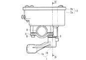
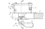
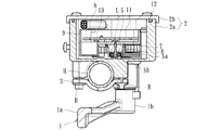
本実施形態に係るスロットルグリップ装置は、ATVやバギー等の車両が具備するハンドルバーに固定されて当該車両のエンジンを制御するためのものであり、図1〜5に示すように、所謂サムレバーと称されるスロットルレバー1と、支持部材2と、検出センサとしての角度センサ10とから主に構成されている。尚、図中符号Hは、車両が具備する操舵用のハンドルバーを示しており、符号Gは、当該ハンドルバーHの先端に取り付けられて運転者が把持可能な把持グリップを示している。
Hereinafter, embodiments of the present invention will be specifically described with reference to the drawings.
The throttle grip device according to the present embodiment is used for controlling an engine of a vehicle that is fixed to a handlebar of a vehicle such as an ATV or a buggy. As shown in FIGS. It is mainly composed of a so-called throttle lever 1, a
スロットルレバー1は、把持グリップG近傍に配設され、当該把持グリップGを把持しつつ回動操作可能とされたものであり、延設端部の操作部1aと、回動軸としての軸部1bとが一体形成されて成る。即ち、軸部1bが上下に延設されて回動軸を成すとともに、そこから側方に操作部1aが延設されて、例えば把持グリップGを把持した親指を延ばして当該操作部1aを押圧することにより回動操作が可能とされている。 The throttle lever 1 is disposed in the vicinity of the grip grip G, and can be rotated while gripping the grip grip G. The throttle lever 1 has an operation portion 1a at an extended end and a shaft portion as a rotation shaft. 1b is integrally formed. That is, the shaft portion 1b extends vertically to form a rotation shaft, and the operation portion 1a extends from the side to extend the thumb holding the grip grip G and presses the operation portion 1a. By doing so, the turning operation is made possible.
支持部材2は、ハンドルバーHに固定されてスロットルレバー1を回動自在に支持するものであり、収容ケース2a及び蓋部材2bにより内部に収容空間Aが形成されて成るものである。具体的には、支持部材2には、ハンドルバーHを挟持し得るホルダ3が形成されており、当該ホルダ3をボルトBにて締め上げることにより当該ハンドルバーHに支持部材2が固定されるようになっている。
The
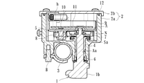
収容空間Aから下方に向かって貫通孔Aaが形成されており、この貫通孔Aaにスロットルレバー1の軸部1bが挿通されている。この状態において、軸部1bは、ブッシュ4により貫通孔Aa内で回転自在とされるとともに、基端側が捩りバネから成るリターンスプリングSaにて付勢され、スロットルレバー1を常時初期位置側に付勢し得るよう構成されている。尚、図中符号6は、オイルシール等のシール部材を示している。而して、シール部材6にて貫通孔Aaにおけるシールが図られるとともに、収容ケース2aと蓋部材2bとの間にパッキン12が介在しているため、支持部材2の収容空間Aは、略閉塞空間とされている。
A through hole Aa is formed downward from the housing space A, and the shaft portion 1b of the throttle lever 1 is inserted into the through hole Aa. In this state, the shaft portion 1b is made rotatable in the through hole Aa by the
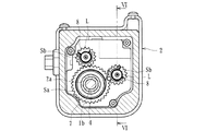
更に、軸部1bの基端側には、ナットNにてスロットルレバー1と一体構成された第1ギア7が取り付けられており、当該スロットルレバー1と共に第1ギア7が回転し得るようになっている。かかる第1ギア7には、その外周面に歯が形成されており、当該歯に噛み合って一対の第2ギア8が配設されている。この第2ギア8は、第1ギアより小径(本実施形態においては1/2の径)な2つの歯車から成り、スロットルレバー1が回動操作されて軸部1b及び第1ギア7が回転すると、それと連動してそれぞれが軸L(図6参照)を中心として回転し得るようになっている。
Further, a
また、第2ギア8には、それぞれ磁石5が形成されており、当該第2ギア8と共に当該磁石5がそれぞれ回転可能とされている。尚、磁石5は、第2ギア8の一部に着磁させたものであっても永久磁石等を嵌め込んだもの等であってもよい。更に、各第2ギア8には、図5、6に示すように、それぞれのギアを所定方向に付勢するギアバネSbが配設されており、第1ギア7との噛み合いにおいてバックラッシを吸収し得るようになっている。
The
角度センサ10は、磁石5からの磁気変化を検出してその回転角を検出するものであり、所定の回路が印刷等にて形成された基板11に配設されるとともに、上述した各第2ギア8及び磁石5に対応した位置(軸Lの延長線上の位置)に配設されて、これら第2ギア8の回転角度を検出し得るよう構成されている。即ち、スロットルレバー1の回動操作に伴い第1ギア7及び第2ギア8が回転し、それと共に磁石5が回転すると、それら磁石5から生じる磁界の変化により角度センサ10の出力信号が増減するので、その出力信号に基づいてスロットルレバー1の回動操作角度を検出し得るようになっている。
The
かかる検出信号は、基板11から延出されたコードhを介して二輪車が具備するECUに送られ、当該検出信号に基づいたエンジンの制御(スロットルレバー1の回動角度に基づいた出力制御)が行われる。尚、例えば、それぞれの角度センサ10から2つの出力信号を出力させるよう構成するのが好ましい。この場合、それぞれの出力電圧が互いに逆向きに変化するよう構成すれば、一方の角度センサ10或いは配線が壊れたとき、その角度センサ10からの出力電圧はダウンして出力信号の和が異なってくるので、当該一方の角度センサ10又は配線に不具合があることが認識できる。この場合であっても、他方の角度センサ10による出力に基づき各種制御が行われ、安全を確保することができる。本スロットルグリップ装置によれば、角度センサ10によりスロットルレバー1の回転操作角度を非接触にて検出することができるので、ポテンションメータ等の機械的機構を有するものに比べ、装置の耐久性を向上させることができる。
The detection signal is sent to the ECU of the two-wheeled vehicle via a cord h extended from the
更に、角度センサ10が配設された基板11は、収容空間A内に収容された収容箱9内に配設されるとともに、当該収容箱9が所定の樹脂で充填されて成るものとされている。これにより、収容箱9内の基板11及び角度センサ10は樹脂にてモールドされることとなる。而して、収容箱9の下方には、第1ギ7ア及び第2ギア8を含むギア群が配設されており、例えば収容ケース2aと蓋部材2bとの間のシール機能が損なわれて、上部から浸水等があった場合でも、当該ギア郡が水に曝されてしまうのを抑制することができる。尚、収容箱9には、スロットルレバー1における軸部1bの基端、及び第2ギア8の軸Lの一端に対応する位置に凹部がそれぞれ形成されている。
Further, the
上記実施形態によれば、支持部材2に収容空間Aを形成し、当該収容空間A内にスロットルレバー1の回動操作角度を検出する角度センサ10(検出センサ)を収容させたので、スロットルレバー1の回動操作角度を精度よくエンジン側に伝達させることができる。また、スロットルレバー1を支持するための支持部材2が角度センサ10(検出センサ)を収容するための収容ケースを兼ねることとなり、部品点数の削減及び製造コストの低減を図ることができる。
According to the above embodiment, the accommodation space A is formed in the
更に、スロットルレバー1と共に回転する第1ギア7と、該第1ギア7より小径とされ、当該第1ギア7と噛み合って連動可能な第2ギア8と、該第2ギア8に形成された磁石5とを具備するとともに、角度センサ10にて当該磁石からの磁気変化を検出してその回転角を検出するよう構成されているので、より精度よくスロットルレバー1の回動操作角度を検出させることができる。
Further, a
また更に、角度センサ10は、所定の電気回路が形成された基板11に配設されるとともに、当該基板11が収容空間A内に収容された収容箱9内に配設され、当該収容箱9が樹脂で充填されて成るので、角度センサ10及びその電気回路の防水を図ることができる。また、第1ギア7及び第2ギア8は収容箱9の下方に配設されたので、角度センサ10及びその電気回路の防水と同時に、その下方の第1ギア7及び第2ギア8(ギア群)の防水をも図ることができる。
Furthermore, the
以上、本実施形態について説明したが、本発明はこれに限定されるものではなく、例えばスロットルレバーの回動操作角度を電気的に検知してスロットル開度を制御するものであれば、角度センサ10に代えて他の検出センサ(本実施形態の如く非接触式センサの他、ポテンショメーター等の接触式センサ含む)としてもよい。また、スロットルレバー1の回動角度を検出センサにて直接検出するものとし、第1ギア7や第2ギア8等から成るギア群を不要としてもよい。尚、本実施形態においては、ATVやバギーのハンドルバーに取り付けられたものとされているが、ハンドルバーを有する他の車両(例えばスノーモービル等)に取り付けるようにしてもよい。
Although the present embodiment has been described above, the present invention is not limited to this. For example, if the throttle opening degree is controlled by electrically detecting the rotation angle of the throttle lever, the angle sensor Instead of 10, other detection sensors (including non-contact type sensors as in the present embodiment and contact type sensors such as potentiometers) may be used. Further, the rotation angle of the throttle lever 1 may be directly detected by a detection sensor, and a gear group including the
支持部材に収容空間を形成し、当該収容空間内に前記スロットルレバーの回動操作角度を検出する検出センサを収容させたスロットル操作装置であれば、外観形状が異なるもの或いは他の機能が付加されたものにも適用することができる。 As long as the throttle operating device has an accommodating space formed in the support member and a detection sensor for detecting the rotation operation angle of the throttle lever is accommodated in the accommodating space, one having a different external shape or another function is added. It can also be applied to other things.
1 スロットルレバー
1a 操作部
1b 軸部
2 支持部材
3 ホルダ
4 ブッシュ
5 磁石
6 シール部材
7 第1ギア
8 第2ギア
9 収容箱
10 角度センサ(検出センサ)
11 基板
12 パッキン
A 収容空間
H ハンドルバー
B ボルト
N ナット
G 把持グリップ
Sa リターンスプリング
Sb ギアバネ
DESCRIPTION OF SYMBOLS 1 Throttle lever 1a Operation part
11
Claims (4)
前記ハンドルバーに固定されて前記スロットルレバーを回動自在に支持する支持部材と、
を具備し、前記支持部材から前記スロットルレバーを延設させて成るとともに、当該スロットルレバーの回動操作角度に基づき車両のエンジンを制御するためのスロットル操作装置において、
前記支持部材に収容空間を形成し、当該収容空間内に前記スロットルレバーの回動操作角度を検出する検出センサを収容させたことを特徴とするスロットル操作装置。 A throttle lever that is disposed in the vicinity of the grip grip attached to the front end of the handlebar of the vehicle, and that can be rotated while gripping the grip grip;
A support member fixed to the handlebar and rotatably supporting the throttle lever;
In the throttle operation device for extending the throttle lever from the support member and controlling the engine of the vehicle based on the rotation operation angle of the throttle lever,
A throttle operating device, wherein an accommodation space is formed in the support member, and a detection sensor for detecting a rotation operation angle of the throttle lever is accommodated in the accommodation space.
該第1ギアより小径とされ、当該第1ギアと噛み合って連動可能な第2ギアと、
該第2ギアに形成された磁石と、
を具備するとともに、前記検出センサは、当該磁石からの磁気変化を検出してその回転角を検出する角度センサから成ることを特徴とする請求項1記載のスロットル操作装置。 A first gear that rotates with the throttle lever;
A second gear that has a smaller diameter than the first gear and is capable of engaging with and engaging with the first gear;
A magnet formed on the second gear;
2. The throttle operating device according to claim 1, wherein the detection sensor includes an angle sensor that detects a rotation angle by detecting a magnetic change from the magnet.
Priority Applications (1)
| Application Number | Priority Date | Filing Date | Title |
|---|---|---|---|
| JP2008222188A JP5175661B2 (en) | 2008-08-29 | 2008-08-29 | Throttle operating device |
Applications Claiming Priority (1)
| Application Number | Priority Date | Filing Date | Title |
|---|---|---|---|
| JP2008222188A JP5175661B2 (en) | 2008-08-29 | 2008-08-29 | Throttle operating device |
Publications (2)
| Publication Number | Publication Date |
|---|---|
| JP2010053836A true JP2010053836A (en) | 2010-03-11 |
| JP5175661B2 JP5175661B2 (en) | 2013-04-03 |
Family
ID=42070008
Family Applications (1)
| Application Number | Title | Priority Date | Filing Date |
|---|---|---|---|
| JP2008222188A Active JP5175661B2 (en) | 2008-08-29 | 2008-08-29 | Throttle operating device |
Country Status (1)
| Country | Link |
|---|---|
| JP (1) | JP5175661B2 (en) |
Cited By (5)
| Publication number | Priority date | Publication date | Assignee | Title |
|---|---|---|---|---|
| JP2020138679A (en) * | 2019-03-01 | 2020-09-03 | 朝日電装株式会社 | Throttle operation device |
| US20220178312A1 (en) * | 2020-12-04 | 2022-06-09 | Asahi Denso Co., Ltd. | Throttle operating device |
| US11492984B2 (en) | 2020-12-04 | 2022-11-08 | Asahi Denso Co., Ltd. | Throttle operating device |
| US11668254B2 (en) | 2020-12-04 | 2023-06-06 | Asahi Denso Co., Ltd. | Throttle operating device |
| US11762411B2 (en) | 2020-12-04 | 2023-09-19 | Asahi Denso Co., Ltd. | Throttle operating device |
Citations (2)
| Publication number | Priority date | Publication date | Assignee | Title |
|---|---|---|---|---|
| JP2002256904A (en) * | 2001-02-28 | 2002-09-11 | Mikuni Corp | Accelerator operation device |
| JP2004314929A (en) * | 2003-02-27 | 2004-11-11 | Asahi Denso Co Ltd | Throttle opening detecting device |
-
2008
- 2008-08-29 JP JP2008222188A patent/JP5175661B2/en active Active
Patent Citations (2)
| Publication number | Priority date | Publication date | Assignee | Title |
|---|---|---|---|---|
| JP2002256904A (en) * | 2001-02-28 | 2002-09-11 | Mikuni Corp | Accelerator operation device |
| JP2004314929A (en) * | 2003-02-27 | 2004-11-11 | Asahi Denso Co Ltd | Throttle opening detecting device |
Cited By (8)
| Publication number | Priority date | Publication date | Assignee | Title |
|---|---|---|---|---|
| JP2020138679A (en) * | 2019-03-01 | 2020-09-03 | 朝日電装株式会社 | Throttle operation device |
| JP7253166B2 (en) | 2019-03-01 | 2023-04-06 | 朝日電装株式会社 | Throttle operating device |
| JP7408073B2 (en) | 2019-03-01 | 2024-01-05 | 朝日電装株式会社 | throttle operating device |
| US20220178312A1 (en) * | 2020-12-04 | 2022-06-09 | Asahi Denso Co., Ltd. | Throttle operating device |
| US11492984B2 (en) | 2020-12-04 | 2022-11-08 | Asahi Denso Co., Ltd. | Throttle operating device |
| US11668254B2 (en) | 2020-12-04 | 2023-06-06 | Asahi Denso Co., Ltd. | Throttle operating device |
| US11761388B2 (en) | 2020-12-04 | 2023-09-19 | Asahi Denso Co., Ltd. | Throttle operating device |
| US11762411B2 (en) | 2020-12-04 | 2023-09-19 | Asahi Denso Co., Ltd. | Throttle operating device |
Also Published As
| Publication number | Publication date |
|---|---|
| JP5175661B2 (en) | 2013-04-03 |
Similar Documents
| Publication | Publication Date | Title |
|---|---|---|
| JP5175661B2 (en) | Throttle operating device | |
| JP5543224B2 (en) | Lever type throttle operating device | |
| US6920805B2 (en) | Throttle-opening detecting apparatus | |
| JP5175660B2 (en) | Throttle grip device | |
| JP4255405B2 (en) | Throttle grip device | |
| JP2018091201A (en) | Throttle grip device | |
| JP6370108B2 (en) | Throttle grip device | |
| JP6178070B2 (en) | Throttle grip device | |
| JP7146216B2 (en) | throttle grip device | |
| JP6370109B2 (en) | Throttle grip device | |
| JP5536466B2 (en) | Throttle device | |
| JP4266330B2 (en) | Throttle opening detection device | |
| JP6918296B2 (en) | Throttle grip device | |
| JP4759485B2 (en) | Composite sensor for vehicle | |
| JP7272545B2 (en) | throttle grip device | |
| JP6868866B2 (en) | Throttle grip device | |
| WO2020178861A2 (en) | Multi-function throttle of vehicle | |
| JP2011157886A (en) | Throttle device | |
| JP5710949B2 (en) | Throttle device | |
| JP2010053729A (en) | Throttle grip device | |
| JP6211264B2 (en) | Throttle grip device | |
| JP7312998B2 (en) | throttle grip device | |
| JP7312999B2 (en) | throttle grip device | |
| JP6993642B2 (en) | Throttle grip device | |
| JP2019105206A (en) | Throttle grip device |
Legal Events
| Date | Code | Title | Description |
|---|---|---|---|
| A621 | Written request for application examination |
Free format text: JAPANESE INTERMEDIATE CODE: A621 Effective date: 20110826 |
|
| A131 | Notification of reasons for refusal |
Free format text: JAPANESE INTERMEDIATE CODE: A131 Effective date: 20120528 |
|
| A977 | Report on retrieval |
Free format text: JAPANESE INTERMEDIATE CODE: A971007 Effective date: 20120531 |
|
| A521 | Request for written amendment filed |
Free format text: JAPANESE INTERMEDIATE CODE: A523 Effective date: 20120724 |
|
| A02 | Decision of refusal |
Free format text: JAPANESE INTERMEDIATE CODE: A02 Effective date: 20120823 |
|
| A521 | Request for written amendment filed |
Free format text: JAPANESE INTERMEDIATE CODE: A523 Effective date: 20121120 |
|
| A911 | Transfer to examiner for re-examination before appeal (zenchi) |
Free format text: JAPANESE INTERMEDIATE CODE: A911 Effective date: 20121128 |
|
| TRDD | Decision of grant or rejection written | ||
| A01 | Written decision to grant a patent or to grant a registration (utility model) |
Free format text: JAPANESE INTERMEDIATE CODE: A01 Effective date: 20121218 |
|
| A61 | First payment of annual fees (during grant procedure) |
Free format text: JAPANESE INTERMEDIATE CODE: A61 Effective date: 20130107 |
|
| R150 | Certificate of patent or registration of utility model |
Ref document number: 5175661 Country of ref document: JP Free format text: JAPANESE INTERMEDIATE CODE: R150 |
|
| R250 | Receipt of annual fees |
Free format text: JAPANESE INTERMEDIATE CODE: R250 |
|
| R250 | Receipt of annual fees |
Free format text: JAPANESE INTERMEDIATE CODE: R250 |
|
| R250 | Receipt of annual fees |
Free format text: JAPANESE INTERMEDIATE CODE: R250 |
|
| R250 | Receipt of annual fees |
Free format text: JAPANESE INTERMEDIATE CODE: R250 |
|
| R250 | Receipt of annual fees |
Free format text: JAPANESE INTERMEDIATE CODE: R250 |
|
| R250 | Receipt of annual fees |
Free format text: JAPANESE INTERMEDIATE CODE: R250 |
|
| R250 | Receipt of annual fees |
Free format text: JAPANESE INTERMEDIATE CODE: R250 |
|
| R250 | Receipt of annual fees |
Free format text: JAPANESE INTERMEDIATE CODE: R250 |
|
| R250 | Receipt of annual fees |
Free format text: JAPANESE INTERMEDIATE CODE: R250 |