JP2010053794A - Control device of internal combustion engine - Google Patents
Control device of internal combustion engine Download PDFInfo
- Publication number
- JP2010053794A JP2010053794A JP2008220508A JP2008220508A JP2010053794A JP 2010053794 A JP2010053794 A JP 2010053794A JP 2008220508 A JP2008220508 A JP 2008220508A JP 2008220508 A JP2008220508 A JP 2008220508A JP 2010053794 A JP2010053794 A JP 2010053794A
- Authority
- JP
- Japan
- Prior art keywords
- internal combustion
- combustion engine
- alternator
- power generation
- generator
- Prior art date
- Legal status (The legal status is an assumption and is not a legal conclusion. Google has not performed a legal analysis and makes no representation as to the accuracy of the status listed.)
- Pending
Links
Images


Abstract
Description
本発明は、車両の駆動源となる内燃機関(エンジン)を自動停止・自動始動させるアイドルストップシステムを備えた内燃機関の制御装置に関する発明である。 The present invention relates to a control device for an internal combustion engine including an idle stop system that automatically stops and automatically starts an internal combustion engine (engine) serving as a drive source of a vehicle.
近年、益々厳しくなる燃費向上(CO2 削減)の要求を満たすために、アイドルストップシステム(自動停止・自動始動装置)を搭載した車両が増加している。このアイドルストップシステムを搭載した車両は、市街地走行時等に頻繁に自動停止・自動始動が繰り返されるため、自動始動時のエンジン回転吹き上がりやそれに伴う騒音を低減して運転者に違和感を感じさせないようにすることが近年の重要な技術的課題となっている。 In recent years, vehicles equipped with an idle stop system (automatic stop / automatic starter) are increasing in order to satisfy increasingly demanding improvements in fuel consumption (CO 2 reduction). Vehicles equipped with this idle stop system are frequently repeatedly automatically stopped and automatically started when driving in urban areas, etc. It has become an important technical issue in recent years.
そこで、特許文献1(特開2004−156488号公報)に記載されたシステムにおいは、発電機とスタータ(モータ)とを兼用するモータジェネレータを車両に搭載し、自動始動時にモータジェネレータに正のトルクを発生させることで、エンジンをクランキングして自己着火させて始動し、その始動完了を検出した後に、モータジェネレータの電機子相間端子を短絡して該モータジェネレータに負のトルクを発生させることで、エンジン回転吹き上がり(エンジン回転速度のオーバーシュート)を抑制するようにしている。
しかし、上記特許文献1の構成では、自動始動時にモータジェネレータに正のトルクを発生させることで、エンジンをクランキングして自己着火させて始動し、その始動完了を検出してからモータジェネレータに負のトルクを発生させてエンジン回転吹き上がりを抑制するようにしているため、自動始動時に最初の完爆直後に瞬時に発生するエンジン回転吹き上がりに対して、モータジェネレータに負のトルクを発生させるタイミングが遅れてエンジン回転吹き上がりを十分に抑制できない可能性がある。モータジェネレータは、始動完了を検出するまでは正のトルクを発生させてエンジンをクランキングするスタータとして作動させなければならないため、始動完了を検出するまでは、モータジェネレータに負のトルクを発生させることができず、モータジェネレータに負のトルクを発生させるタイミングが遅れてしまうことは避けられない。しかも、上記特許文献1に記載の発明は、発電機・スタータ兼用のモータジェネレータを搭載した車両にしか適用できず、発電機とスタータとをそれぞれ搭載した一般的な車両には適用できない。 However, in the configuration of the above-mentioned Patent Document 1, a positive torque is generated in the motor generator at the time of automatic start so that the engine is cranked and self-ignited to start, and after the start completion is detected, the motor generator is negatively charged. Is generated to suppress the engine rotation blow-up, so the negative timing is generated in the motor generator against the engine rotation blow-up that occurs instantaneously immediately after the first complete explosion at the time of automatic start. There is a possibility that the engine speed will not be sufficiently suppressed due to delay. Since the motor generator must operate as a starter that cranks the engine by generating a positive torque until the start completion is detected, the motor generator must generate a negative torque until the start completion is detected. Therefore, it is inevitable that the timing for generating the negative torque in the motor generator is delayed. In addition, the invention described in Patent Document 1 can be applied only to a vehicle on which a generator / starter motor generator is mounted, and not to a general vehicle on which a generator and a starter are mounted.
本発明はこれらの事情を考慮してなされたものであり、従ってその目的は、発電機とスタータとをそれぞれ搭載したアイドルストップ機能付き車両において、自動始動時の内燃機関回転速度の吹き上がりを確実に抑制することができる内燃機関の制御装置を提供することにある。 The present invention has been made in consideration of these circumstances. Therefore, the object of the present invention is to ensure that the rotational speed of the internal combustion engine at the time of automatic start-up increases in a vehicle with an idle stop function, each equipped with a generator and a starter. An object of the present invention is to provide a control device for an internal combustion engine that can be suppressed to a low level.
上記目的を達成するために、請求項1に係る発明は、車両の駆動源となる内燃機関を自動停止・自動始動させるアイドルストップ手段と、前記アイドルストップ手段による自動停止中に自動始動要求が発生したときに前記内燃機関をクランキングして自動始動させるスタータと、前記内燃機関の動力により駆動されて発電する発電機と、前記発電機の発電電圧を制御する制御手段とを備えた内燃機関の制御装置において、前記制御手段によって自動始動時に前記発電機の発電電圧を手動始動時よりも上昇させるように制御して自動始動時の内燃機関回転速度の吹き上がりを抑制するようにしたものである。 In order to achieve the above object, according to the first aspect of the present invention, there is provided an idle stop means for automatically stopping and automatically starting an internal combustion engine serving as a vehicle drive source, and an automatic start request is generated during the automatic stop by the idle stop means. An internal combustion engine comprising: a starter that cranks the internal combustion engine to automatically start the engine; a generator that is driven by the power of the internal combustion engine to generate power; and a control unit that controls a power generation voltage of the generator. In the control device, the control means controls the power generation voltage of the generator to be higher than that at the time of manual start by the automatic start so as to suppress an increase in the internal combustion engine rotation speed at the time of automatic start. .
この構成では、発電機とスタータとをそれぞれ搭載したアイドルストップ機能付き車両において、自動始動時に始動完了を検出する前から、発電機の発電電圧を上昇させて内燃機関に対する発電機の負荷トルクを増大させることができるため、発電機の負荷トルクを増大させるタイミングが遅れることはなく、自動始動時の内燃機関回転速度の吹き上がりを発電機の負荷トルクによって確実に抑制することができる。 In this configuration, in a vehicle with an idle stop function, each equipped with a generator and a starter, the generator generated voltage is increased to increase the load torque of the generator with respect to the internal combustion engine before the start completion is detected at the time of automatic start. Therefore, the timing for increasing the load torque of the generator is not delayed, and the blow-up of the internal combustion engine rotation speed at the time of automatic start can be reliably suppressed by the load torque of the generator.
一般に、アイドルストップによる自動始動は、暖機状態から始動するため、冷機状態から始動する手動始動時と比較して、始動性が良く、内燃機関回転速度の吹き上がりが発生しやすいという事情がある。この点を考慮して、本発明は、自動始動時に始動完了を検出する前から、内燃機関に対する発電機の負荷トルク(発電電圧)を増大させて内燃機関回転速度の吹き上がりを確実に抑制することを可能とするものであるが、何等かの原因(例えばバッテリ電圧低下等)で、自動始動時のスタータの駆動力が低下することがある。このような場合に、発電機の負荷トルクが大きいと、始動性が悪くなる。 In general, since the automatic start by the idle stop is started from the warm-up state, the startability is better than that at the time of the manual start starting from the cold state, and the internal combustion engine rotational speed is likely to increase. . In view of this point, the present invention reliably increases the rotational speed of the internal combustion engine by increasing the load torque (power generation voltage) of the generator with respect to the internal combustion engine before the completion of the start is detected during automatic start. However, for some reason (for example, a decrease in battery voltage), the driving force of the starter at the time of automatic start may be reduced. In such a case, when the load torque of the generator is large, the startability is deteriorated.
この対策として、請求項2のように、自動始動時に内燃機関回転上昇速度を判定し、該内燃機関回転上昇速度が所定値よりも遅いときには該発電機の発電電圧を低下又は0とするように制御することが好ましい。要するに、自動始動時の内燃機関回転上昇速度が速いか遅いかで始動性が良いか悪いかを判定できるため、自動始動時の内燃機関回転上昇速度が遅く、始動性が悪いと判定されるときに、直ちに発電機の発電電圧を低下又は0とすれば、何等かの原因でスタータの駆動力が低下している場合に、内燃機関に対する発電機の負荷トルクを軽減させて、始動性を確保することができる。 As a countermeasure against this, as in claim 2, the internal combustion engine rotational increase speed is determined at the time of automatic start, and when the internal combustion engine rotational increase speed is slower than a predetermined value, the generated voltage of the generator is reduced or made zero. It is preferable to control. In short, because it is possible to determine whether the startability is good or bad depending on whether the internal combustion engine rotation speed is high or low at the time of automatic start, the internal combustion engine speed increase speed at the time of automatic start is slow and it is determined that the startability is poor In addition, if the generator voltage is immediately reduced or reduced to 0, the starter driving force is reduced for any reason and the generator load torque is reduced to ensure startability. can do.
本発明は、自動始動時に内燃機関回転上昇速度を判定する場合、自動始動当初から発電機の発電電圧を手動始動時よりも上昇させた状態で始動し、内燃機関回転上昇速度が遅いときに発電機の発電電圧を低下又は0とするようにしても良いし、或は、請求項3のように、自動始動時に内燃機関回転上昇速度が所定値を越えたときに発電機の発電電圧を上昇させて内燃機関回転速度の吹き上がりを抑制し、該内燃機関回転上昇速度が所定値以下のときには発電機の発電電圧を低下又は0とするように制御するようにしても良い。この場合は、自動始動当初から発電機の発電電圧を手動始動時より上昇させなくても良いし、或は、自動始動当初から発電機の発電電圧を手動始動時より少し上昇させた状態で始動し、内燃機関回転上昇速度が所定値を越えたときに発電機の発電電圧を更に上昇させて内燃機関回転速度の吹き上がりを抑制するようにしても良い。いずれの場合でも、自動始動時の始動性を確保しながら内燃機関回転速度の吹き上がりを抑制することができる。 In the present invention, when determining the internal combustion engine rotation increase speed at the time of automatic start, the engine is started in a state where the power generation voltage of the generator is increased from the start of the automatic start than at the time of manual start. The generator power generation voltage may be reduced or reduced to 0, or the generator power generation voltage may be increased when the internal combustion engine rotational speed exceeds a predetermined value during automatic start. Thus, it is possible to suppress the increase in the internal combustion engine rotational speed, and to control so that the power generation voltage of the generator decreases or becomes zero when the internal combustion engine rotational increase speed is equal to or less than a predetermined value. In this case, it is not necessary to increase the generator voltage from the beginning of the automatic start compared to the time of manual start, or the generator is started with the generator voltage slightly increased from the start of the automatic start. Then, when the internal combustion engine rotational speed increases beyond a predetermined value, the power generation voltage of the generator may be further increased to suppress the internal combustion engine rotational speed from rising. In any case, it is possible to suppress the increase in the internal combustion engine rotation speed while ensuring the startability at the time of automatic start.
以下、本発明を実施するための最良の形態を具体化した3つの実施例1〜3を説明する。 Hereinafter, three Examples 1 to 3 embodying the best mode for carrying out the present invention will be described.
本発明の実施例1を図1乃至図4に基づいて説明する。
まず、図1に基づいてエンジン制御システム全体の構成を概略的に説明する。
エンジン11の吸気ポート12に接続された吸気管13の途中には、スロットルバルブ14が設けられ、このスロットルバルブ14の開度(スロットル開度)がスロットル開度センサ15によって検出される。吸気管13には、スロットルバルブ14をバイパスするバイパス通路16が設けられ、このバイパス通路16の途中に、アイドルスピードコントロールバルブ17が設けられている。尚、バイパス通路16とアイドルスピードコントロールバルブ17を省略して、アイドル時もスロットルバルブ14の開度調整によって吸入空気量を調整してアイドル回転速度を制御する構成としても良い。
A first embodiment of the present invention will be described with reference to FIGS.
First, the overall configuration of the engine control system will be schematically described with reference to FIG.
A
スロットルバルブ14の下流側には、吸気管圧力を検出する吸気管圧力センサ18が設けられ、各気筒の吸気ポート12の近傍には、燃料噴射弁19が取付けられている。
一方、エンジン11の排気ポート20に接続された排気管21の途中には、排出ガス浄化用の触媒22が設置され、この触媒22の上流側には、排出ガスの空燃比又はリッチ/リーンを検出する排出ガスセンサ31(空燃比又は酸素センサ等)が設けられている。
An intake
On the other hand, an exhaust gas purifying
エンジン11のシリンダブロックには、冷却水温を検出する冷却水温センサ23が設けられている。エンジン11のクランク軸24に取付けられたシグナルロータ25の外周に対向してクランク角センサ26が設置され、このクランク角センサ26からシグナルロータ25の回転に同期して所定クランク角毎にクランクパルス信号が出力され、このクランクパルス信号の周期(周波数)に基づいてエンジン回転速度が検出される。
The cylinder block of the
エンジン11のカム軸27に取付けられたシグナルロータ28の外周に対向してカム角センサ29が設置され、このカム角センサ29からシグナルロータ28の回転に同期して所定のカム角でカムパルス信号が出力され、このカムパルス信号に基づいてカム角基準位置が検出され、これを基準にしてクランクパルス信号をカウントすることで、そのカウント値からクランク角が検出される。
A
また、クランク軸24に連結されたクランクプーリ34の回転がベルト35を介してオルタネータ33(発電機)に伝達されることで、エンジン11の動力でオルタネータ33が回転駆動されて発電するようになっている。このオルタネータ33の界磁電流をデューティ制御等により制御することで、オルタネータ33の発電電圧(負荷トルク)を制御するようになっている。
Further, the rotation of the
一方、図2に示すように、イグニッションスイッチ36をOFF接点からIG接点に切り換えると、車両に搭載されたバッテリ37からECU30に電源が投入される。更に、イグニッションスイッチ36をIG接点からST接点に切り換えると、スタータリレー38の駆動コイル38aに通電されて、そのリレースイッチ38bがオンしてスタータ39に通電され、スタータ39が回転してエンジン11をクランキングして始動させる。
On the other hand, as shown in FIG. 2, when the
前述したクランク角センサ26等の各種センサの出力は、エンジン制御回路(以下「ECU」と表記する)30に入力される。このECU30は、マイクロコンピュータを主体として構成され、各種センサで検出したエンジン運転状態に応じて、燃料噴射弁19の燃料噴射量や噴射時期と点火プラグ31の点火時期を制御する。
Outputs of various sensors such as the
更に、ECU30は、特許請求の範囲でいうアイドルストップ手段として機能し、エンジン運転中に所定の自動停止条件(例えばアクセル全閉、アイドル回転中、停車中、暖機後等)が成立して自動停止要求が発生したときに、エンジン11の燃焼(点火及び/又は燃料噴射)を停止させてエンジン回転を自動停止させるアイドルストップを実行し、このアイドルストップによる自動停止中に、運転者が車両を発進させる操作(例えばアクセルペダルの踏み込み等)又は車両発進のための準備操作(例えばブレーキ操作解除、シフトレバーの走行レンジへのシフト操作等)を行ったときに、自動始動要求が発生して、スタータリレー38の駆動コイル38aに通電されて、そのリレースイッチ38bがオンしてスタータ39に通電され、スタータ39が回転してエンジン11をクランキングして自動始動させる。尚、自動停止中に、空調装置等の補機類(電気負荷)からの要求によって自動始動要求が発生することもある。
Further, the
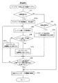
更に、ECU30は、図3のオルタネータ発電電圧制御プログラムを実行することで、オルタネータ33の発電電圧(負荷トルク)を制御する制御手段としての役割を果たす。図3のオルタネータ発電電圧制御プログラムは、ECU30の電源オン期間中に所定周期で繰り返し実行される。
Further, the
本プログラムが起動されると、まずステップ101で、自動始動時か否か(自動始動要求が発生しているか否か)を判定し、自動始動時ではないと判定されれば、ステップ102に進み、運転者がイグニッションスイッチ36をST接点に切り換えてスタータ39に通電してエンジン11を始動する“手動始動時”であるか否かを判定する。その結果、手動始動時と判定されれば、ステップ104に進み、オルタネータ33の発電電圧を手動始動時の設定電圧に設定してスタータ39に通電してエンジン11を始動する。この際、手動始動時の設定電圧は、後述する自動始動時の設定電圧よりも低い電圧に設定される。
When this program is started, first, at
尚、上記ステップ101、102で、自動始動時、手動始動時のいすれでもないと判定されれば、ステップ106に進み、通常のオルタネータ発電電圧制御を実行し、バッテリ37の充電状態と電気負荷の消費電力等に応じてオルタネータ33の発電電圧を設定する。
If it is determined in
一方、上記ステップ101で、自動始動時と判定されれば、ステップ103に進み、オルタネータ33の発電電圧を手動始動時の設定電圧よりも高い電圧(例えば制御可能な発電電圧範囲の最高電圧)に設定してスタータ39に通電してエンジン11を自動始動する。自動始動時、手動始動時のいずれの場合も、ステップ105で、エンジン回転速度が目標アイドル回転速度付近に収束したか否かを判定し、エンジン回転速度が目標アイドル回転速度付近に収束するまで、自動始動時又は手動始動時の発電電圧制御を続ける。
On the other hand, if it is determined at the time of the above-mentioned
この後、エンジン回転速度が目標アイドル回転速度付近に収束した時点で、ステップ106に進み、通常のオルタネータ発電電圧制御を実行し、バッテリ37の充電状態と電気負荷の消費電力等に応じてオルタネータ33の発電電圧を設定する。尚、自動始動時(手動始動時)の発電電圧制御を所定時間行った後に、通常のオルタネータ発電電圧制御を実行するようにしても良い。
Thereafter, when the engine speed has converged near the target idle speed, the routine proceeds to step 106 where normal alternator power generation voltage control is executed, and the
以上説明した本実施例1によれば、図4に示すように、アイドルストップによる自動停止中に、自動始動要求が発生したときにオルタネータ33の発電電圧を従来の設定電圧よりも高い電圧(例えば制御可能な発電電圧範囲の最高電圧)に設定してスタータ39に通電してエンジン11を自動始動する。
According to the first embodiment described above, as shown in FIG. 4, the power generation voltage of the
従来は、自動始動時のオルタネータ33の発電電圧が低く、オルタネータ33の負荷トルクが小さいために、自動始動時にエンジン回転速度の吹き上がりが発生していたが、本実施例1では、自動始動時にオルタネータ33の発電電圧を従来よりも高い電圧(例えば制御可能な発電電圧範囲の最高電圧)に設定して、エンジン11に対するオルタネータ33の負荷トルクを増大させるため、自動始動時のエンジン回転速度の吹き上がりをオルタネータ33の負荷トルクによって確実に抑制することができる。
Conventionally, since the generated voltage of the
上述したように、本実施例1では、オルタネータ33とスタータ39とをそれぞれ搭載したアイドルストップ機能付き車両において、自動始動時に始動完了を検出する前から、オルタネータ33の発電電圧を上昇させてエンジン11に対するオルタネータ33の負荷トルクを増大させることができるため、自動始動にオルタネータ33の負荷トルクを増大させるタイミングが遅れることはなく、自動始動時のエンジン回転速度の吹き上がりをオルタネータ33の負荷トルクによって確実に抑制することができる。
As described above, in the first embodiment, in the vehicle with the idling stop function in which the
一般に、アイドルストップによる自動始動は、暖機状態から始動するため、冷機状態から始動する手動始動時と比較して、始動性が良く、エンジン回転速度の吹き上がりが発生しやすいという事情がある。この点を考慮して、本発明は、自動始動時に始動完了を検出する前から、エンジン11に対するオルタネータ33の負荷トルク(発電電圧)を増大させてエンジン回転速度の吹き上がりを確実に抑制するようにしているが、何等かの原因(例えばバッテリ37の電圧低下等)で、自動始動時のスタータ39の駆動力が低下することがある。このような場合に、オルタネータ33の負荷トルクが大きいと、始動性が悪くなる。
In general, since the automatic start by the idle stop is started from the warm-up state, the startability is better than that at the manual start starting from the cold state, and the engine speed is likely to increase. In view of this point, the present invention increases the load torque (power generation voltage) of the
この対策として、本発明の実施例2では、図5のオルタネータ発電電圧制御プログラムを実行することで、何等かの原因で、自動始動時のスタータ39の駆動力が低下している場合でも、始動性を確保できるようにしている。以下、図5のオルタネータ発電電圧制御プログラムの処理内容を説明する。
As a countermeasure against this, in the second embodiment of the present invention, the alternator power generation voltage control program of FIG. 5 is executed, so that even if the driving force of the
図5のオルタネータ発電電圧制御プログラムにおいても、手動始動時のオルタネータ33の発電電圧制御(ステップ201→202→204→208→209)は、前記実施例1と同じである。
Also in the alternator power generation voltage control program of FIG. 5, the power generation voltage control (step 201 → 202 → 204 → 208 → 209) of the
これに対し、ステップ201で、自動始動時と判定されれば、ステップ203に進み、オルタネータ33の発電電圧を手動始動時の設定電圧よりも高い電圧(例えば制御可能な発電電圧範囲の最高電圧)に設定してスタータ39に通電してエンジン11を自動始動する。この後、ステップ205に進み、エンジン回転上昇速度(例えば演算周期当たりのエンジン回転速度上昇量)を算出し、次のステップ206で、エンジン回転上昇速度が所定値よりも遅いか否かで、始動性が悪いか否かを判定する。その結果、エンジン回転上昇速度が所定値よりも遅く、始動性が悪いと判定されれば、ステップ207に進み、オルタネータ33の発電電圧を低下させる。この際、オルタネータ33の発電電圧を所定電圧だけ低下させても良いし、予め決められた電圧(例えば手動始動時と同じ電圧)に低下させるようにしたり、或は、オルタネータ33の発電電圧を0としても良い。
On the other hand, if it is determined in
上記ステップ206で、エンジン回転上昇速度が所定値以上と判定されれば、始動性が良いと判断して、自動始動当初のオルタネータ33の発電電圧をそのまま維持する。
この後、ステップ208に進み、エンジン回転速度が目標アイドル回転速度付近に収束したか否かを判定し、エンジン回転速度が目標アイドル回転速度付近に収束するまで、上記ステップ205、206の処理を所定周期で繰り返し実行し、エンジン回転上昇速度が所定値よりも遅く、始動性が悪いと判定されれば、オルタネータ33の発電電圧を低下させる。
If it is determined in
Thereafter, the process proceeds to step 208, where it is determined whether or not the engine rotational speed has converged near the target idle rotational speed, and the processing of
その後、エンジン回転速度が目標アイドル回転速度付近に収束した時点で、ステップ209に進み、通常のオルタネータ発電電圧制御を実行し、バッテリ37の充電状態と電気負荷の消費電力等に応じてオルタネータ33の発電電圧を設定する。
Thereafter, when the engine speed has converged near the target idle speed, the routine proceeds to step 209, where the normal alternator power generation voltage control is executed, and the
以上説明した本実施例2によれば、自動始動時のエンジン回転上昇速度が遅いか否かで始動性が悪いか否かを判定して、始動性が悪いと判定されたときに、直ちにオルタネータ33の発電電圧を低下又は0とするようにしたので、何等かの原因でスタータ39の駆動力が低下している場合に、エンジン11に対するオルタネータ33の負荷トルクを軽減させて、始動性を確保することができる。
According to the second embodiment described above, it is determined whether or not the startability is poor depending on whether or not the engine rotational speed at the time of automatic start is slow. Since the power generation voltage of 33 is reduced or set to 0, when the driving force of the
上記実施例2では、自動始動当初からオルタネータ33の発電電圧を手動始動時よりも上昇させた状態で始動し、エンジン回転上昇速度が遅く、始動性が悪いと判定されたときに、直ちにオルタネータ33の発電電圧を低下又は0とするようにしたが、本発明の実施例3では、図6のオルタネータ発電電圧制御プログラムのステップ201→203aで、自動始動時に、最初にオルタネータ33の発電電圧を所定電圧(例えば手動始動時と同じ電圧であっても良いし、それとは異なる電圧であっても良い)に設定してスタータ39に通電してエンジン11を自動始動する。
In the second embodiment, the
この後、ステップ205に進み、エンジン回転上昇速度(例えば演算周期当たりのエンジン回転速度上昇量)を算出し、次のステップ206で、エンジン回転上昇速度が所定値よりも遅いか否かで、始動性が悪いか否かを判定する。その結果、エンジン回転上昇速度が所定値以上で、始動性が良いと判定されれば、ステップ207aに進み、オルタネータ33の発電電圧を上昇させる。この際、オルタネータ33の発電電圧を所定電圧だけ上昇させても良いし、予め決められた電圧(例えば制御可能な発電電圧範囲の最高電圧)に上昇させるようにしても良い。
Thereafter, the process proceeds to step 205, where the engine speed increase rate (for example, the engine speed increase amount per calculation cycle) is calculated, and in the
一方、上記ステップ206で、エンジン回転上昇速度が所定値よりも遅く、始動性が悪いと判定されれば、ステップ207bに進み、オルタネータ33の発電電圧を低下させる。この際、オルタネータ33の発電電圧を所定電圧だけ低下させても良いし、予め決められた電圧(例えば手動始動時と同じ電圧)に低下させるようにしたり、或は、オルタネータ33の発電電圧を0としても良い。
On the other hand, if it is determined in
この後、ステップ208に進み、エンジン回転速度が目標アイドル回転速度付近に収束するまで、上記ステップ205〜207a又は207bの処理を所定周期で繰り返し実行して、自動始動時にエンジン回転上昇速度が所定値よりも速いか遅いかで、オルタネータ33の発電電圧を上昇又は低下させる。この際、エンジン回転上昇速度が所定値付近でオルタネータ33の発電電圧の上昇と低下が頻繁に切り換えられるチャタリングを防止するために、ステップ206で判定しきい値として用いる「所定値」にヒステリシスを持たせるようにすると良い。その後、エンジン回転速度が目標アイドル回転速度付近に収束した時点で、ステップ209に進み、通常のオルタネータ発電電圧制御を実行し、バッテリ37の充電状態と電気負荷の消費電力等に応じてオルタネータ33の発電電圧を設定する。
Thereafter, the process proceeds to step 208, and the processing of
以上説明した本実施例3によれば、自動始動時にエンジン回転上昇速度が所定値よりも速いか遅いかで、オルタネータ33の発電電圧(負荷トルク)を上昇又は低下させるようにしたので、自動始動時の始動性を確保しながらエンジン回転速度の吹き上がりを抑制することができる。
According to the third embodiment described above, since the power generation voltage (load torque) of the
尚、本発明は、エンジン制御装置(エンジンECU)とアイドルストップ制御装置(アイドルストップECU)とを別々のECUで構成しても良いし、これらを1つのECUで構成しても良い。 In the present invention, the engine control device (engine ECU) and the idle stop control device (idle stop ECU) may be configured by separate ECUs, or may be configured by one ECU.
11…エンジン(内燃機関)、13…吸気管、14…スロットルバルブ、19…燃料噴射弁、21…排気管、26…クランク角センサ、29…カム角センサ、30…ECU(制御手段、アイドルストップ手段)、33…オルタネータ(発電機)、37…バッテリ、38…スタータリレー、39…スタータ
DESCRIPTION OF
Claims (3)
前記アイドルストップ手段による自動停止中に自動始動要求が発生したときに前記内燃機関をクランキングして自動始動させるスタータと、
前記内燃機関の動力により駆動されて発電する発電機と、
前記発電機の発電電圧を制御する制御手段と
を備えた内燃機関の制御装置において、
前記制御手段は、自動始動時に前記発電機の発電電圧を手動始動時よりも上昇させるように制御して自動始動時の内燃機関回転速度の吹き上がりを抑制することを特徴とする内燃機関の制御装置。 Idle stop means for automatically stopping and automatically starting an internal combustion engine as a drive source of the vehicle;
A starter that cranks and automatically starts the internal combustion engine when an automatic start request occurs during automatic stop by the idle stop means;
A generator that is driven by the power of the internal combustion engine to generate electricity;
A control device for an internal combustion engine, comprising: a control means for controlling a power generation voltage of the generator;
The control means controls the internal combustion engine to suppress the increase in the rotational speed of the internal combustion engine at the time of automatic start by controlling the power generation voltage of the generator to be higher than at the time of manual start at the time of automatic start apparatus.
前記アイドルストップ手段による自動停止中に自動始動要求が発生したときに前記内燃機関をクランキングして自動始動させるスタータと、
前記内燃機関の動力により駆動されて発電する発電機と、
前記発電機の発電電圧を制御する制御手段と
を備えた内燃機関の制御装置において、
前記制御手段は、自動始動時に内燃機関回転上昇速度を判定し、該内燃機関回転上昇速度が所定値を越えたときには前記発電機の発電電圧を上昇させて内燃機関回転速度の吹き上がりを抑制し、該内燃機関回転上昇速度が所定値以下のときには前記発電機の発電電圧を低下又は0とするように制御することを特徴とする内燃機関の制御装置。 Idle stop means for automatically stopping and automatically starting the internal combustion engine mounted on the vehicle;
A starter that cranks and automatically starts the internal combustion engine when an automatic start request occurs during automatic stop by the idle stop means;
A generator that is driven by the power of the internal combustion engine to generate electricity;
A control device for an internal combustion engine, comprising: a control means for controlling a power generation voltage of the generator;
The control means determines an internal combustion engine rotational speed increase at the time of automatic start, and suppresses an increase in the internal combustion engine rotational speed by increasing a power generation voltage of the generator when the internal combustion engine rotational speed exceeds a predetermined value. A control device for an internal combustion engine, characterized in that control is performed so that the generated voltage of the generator is reduced or reduced to zero when the rotational speed of the internal combustion engine is below a predetermined value.
Priority Applications (1)
| Application Number | Priority Date | Filing Date | Title |
|---|---|---|---|
| JP2008220508A JP2010053794A (en) | 2008-08-28 | 2008-08-28 | Control device of internal combustion engine |
Applications Claiming Priority (1)
| Application Number | Priority Date | Filing Date | Title |
|---|---|---|---|
| JP2008220508A JP2010053794A (en) | 2008-08-28 | 2008-08-28 | Control device of internal combustion engine |
Publications (1)
| Publication Number | Publication Date |
|---|---|
| JP2010053794A true JP2010053794A (en) | 2010-03-11 |
Family
ID=42069973
Family Applications (1)
| Application Number | Title | Priority Date | Filing Date |
|---|---|---|---|
| JP2008220508A Pending JP2010053794A (en) | 2008-08-28 | 2008-08-28 | Control device of internal combustion engine |
Country Status (1)
| Country | Link |
|---|---|
| JP (1) | JP2010053794A (en) |
Cited By (4)
| Publication number | Priority date | Publication date | Assignee | Title |
|---|---|---|---|---|
| DE102011086937A1 (en) | 2011-06-08 | 2012-12-13 | Mitsubishi Electric Corporation | Vehicle power supply device |
| JP2015161253A (en) * | 2014-02-28 | 2015-09-07 | ダイハツ工業株式会社 | Control device of idling stop vehicle |
| WO2016031124A1 (en) * | 2014-08-25 | 2016-03-03 | 株式会社デンソー | Start controller for internal combustion engine |
| JP2016166584A (en) * | 2015-03-10 | 2016-09-15 | 富士重工業株式会社 | Automobile |
-
2008
- 2008-08-28 JP JP2008220508A patent/JP2010053794A/en active Pending
Cited By (6)
| Publication number | Priority date | Publication date | Assignee | Title |
|---|---|---|---|---|
| DE102011086937A1 (en) | 2011-06-08 | 2012-12-13 | Mitsubishi Electric Corporation | Vehicle power supply device |
| US8862365B2 (en) | 2011-06-08 | 2014-10-14 | Mitsubishi Electric Corporation | Vehicular power supply device |
| DE102011086937B4 (en) * | 2011-06-08 | 2016-09-29 | Mitsubishi Electric Corporation | Vehicle power supply device |
| JP2015161253A (en) * | 2014-02-28 | 2015-09-07 | ダイハツ工業株式会社 | Control device of idling stop vehicle |
| WO2016031124A1 (en) * | 2014-08-25 | 2016-03-03 | 株式会社デンソー | Start controller for internal combustion engine |
| JP2016166584A (en) * | 2015-03-10 | 2016-09-15 | 富士重工業株式会社 | Automobile |
Similar Documents
| Publication | Publication Date | Title |
|---|---|---|
| JP4144348B2 (en) | Engine start system | |
| EP2420663B1 (en) | Automatic stop/start control device for internal combustion engine | |
| JP4428308B2 (en) | Engine control device | |
| JP2006144567A (en) | Valve timing controller for internal combustion engine | |
| JP2007032358A (en) | Control device for internal combustion engine | |
| JP2007032388A (en) | Start control device for internal combustion engine | |
| WO2012091079A1 (en) | Control device of vehicle | |
| JP2004197719A (en) | Engine starting device | |
| JP4165237B2 (en) | Start control device for internal combustion engine | |
| JP2012102694A (en) | Engine automatic stop and start control apparatus | |
| JP2010053794A (en) | Control device of internal combustion engine | |
| JP2009033950A (en) | Power supply controller | |
| JP4458256B2 (en) | Start control device for internal combustion engine | |
| JP2010116877A (en) | Operation control device of internal combustion engine | |
| JP6367497B2 (en) | VEHICLE CONTROL DEVICE, VEHICLE CONTROL SYSTEM, AND CONTROL METHOD FOR VEHICLE CONTROL DEVICE | |
| JP2004036428A (en) | Control device for internal combustion engine | |
| JP2006170163A (en) | Start control device for internal combustion engine | |
| JP5059043B2 (en) | Engine stop / start control device | |
| JP2005146908A (en) | Vibration dampening control device of internal combustion engine | |
| JP4238925B2 (en) | Fuel property determination device | |
| JP2000265880A (en) | Intake control device for internal combustion engine | |
| JP2002339845A (en) | Start control apparatus for internal combustion engine | |
| JP4923797B2 (en) | Vehicle control device | |
| WO2019159270A1 (en) | Control method for internal combustion engine and control device for internal combustion engine | |
| JP2007138757A (en) | Start control device for internal combustion engine |