JP2010053587A - Dust-removing device - Google Patents
Dust-removing device Download PDFInfo
- Publication number
- JP2010053587A JP2010053587A JP2008219217A JP2008219217A JP2010053587A JP 2010053587 A JP2010053587 A JP 2010053587A JP 2008219217 A JP2008219217 A JP 2008219217A JP 2008219217 A JP2008219217 A JP 2008219217A JP 2010053587 A JP2010053587 A JP 2010053587A
- Authority
- JP
- Japan
- Prior art keywords
- screen
- dust
- downstream
- upstream
- water
- Prior art date
- Legal status (The legal status is an assumption and is not a legal conclusion. Google has not performed a legal analysis and makes no representation as to the accuracy of the status listed.)
- Granted
Links
Images
Abstract
Description
本発明は、水路内の流水中の塵芥を捕捉して除去する除塵装置に関する。 The present invention relates to a dust removing device that captures and removes dust in flowing water in a water channel.
従来、図7および図8に示すように、除塵装置3としては、水路1内の中央位置に、上流側を開口させたエンドレス状の回転スクリーン2が設けられて、この回転スクリーン2の内面2aで塵芥を捕捉しつつ流水を外面2bに通過させるとともに、回転スクリーン2の回転によって、捕捉した塵芥を水中から掻き上げて水路外に排除するようにしたものがある(特許文献1参照)。
Conventionally, as shown in FIGS. 7 and 8, as the
具体的には、前記水路1内の両側位置に、水路1の内壁面から内方に突出する隔壁1aが形成されるとともに、この隔壁1aの下流側の中央位置に、閉塞壁1bが形成されて、この隔壁1aと閉塞壁1bとの間に回転スクリーン2が前開口2cを上流側に向けて配置され、隔壁1aと閉塞壁1bに取付けられたガイド4により、回転スクリーン2の前後の開口端に取付けたエンドレスチェーン5が回転ガイドされるようになっている。なお、回転スクリーン2の後開口2dは閉塞壁1bで閉塞されることになる。
Specifically,
前記回転スクリーン2は、上部が水面上に突出するよう縦長楕円状に形成され、水面上の基板6で支持されたチェーンスプロケット7にエンドレスチェーン5の上部が噛み合わされ、電動モータ8でチェーンスプロケット7を駆動することにより、エンドレスチェーン5とともに回転スクリーン2が回転されるようになる。
The
そして、水路1内の流水は、隔壁1aの間の中央通路1cを通って前開口2cから回転スクリーン2の内面2aに流入し、この内面2aで塵芥が捕捉されつつ外面2bに通過して再び水路1内を流下するようになる。また、内面2aで捕捉された塵芥は、回転スクリーン2の回転によって水中から掻き上げられ、スプレー装置9から噴射される水圧で吹き落されてトラフ10に回収されるようになる。
Then, the flowing water in the
ところで、流水中には、大型の塵芥(例えば10mm以上)や小型の塵芥(例えば3mm以上)が含まれている。したがって、回転スクリーン2として、大型の塵芥を捕捉する粗目スクリーンを用いれば、小型の塵芥を全く捕捉することができず、逆に、小型の塵芥を捕捉する細目スクリーンを用いれば、大型の塵芥も同時に捕捉することで、直ぐに目詰まりを起こすようになる。
By the way, the flowing water contains large dust (for example, 10 mm or more) and small dust (for example, 3 mm or more). Therefore, if a coarse screen that captures a large dust is used as the rotating
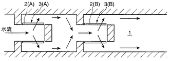
そのために、大型と小型の塵芥を同時に捕捉でき、かつ目詰まりを起こさないようにするためには、図9に示すように、水路1の上流側に、大型の塵芥を捕捉する粗目スクリーン2(A)の除塵装置3(A)を配置し、水路1の下流側に、小型の塵芥を捕捉する細目スクリーン2(B)の除塵装置3(B)を設置する必要がある。
しかしながら、水路の上流側と下流側に2台の除塵装置3(A,B)を設置すれば、設置スペースが大きくなるばかりか、水理損失も大きくなるとともに、各除塵装置3(A,B)から別々に除去した塵芥の処理が煩雑になる等の問題があった。 However, if two dust removing devices 3 (A, B) are installed on the upstream side and the downstream side of the water channel, not only will the installation space be increased, but hydraulic loss will be increased, and each dust removing device 3 (A, B) will be increased. ) Has a problem such as complicated disposal of the dust removed separately.
本発明は、前記問題を解消するためになされたもので、1台の除塵装置の回転スクリーンで、大型と小型の塵芥を目詰まりしないように合理的に捕捉でき、設置スペースや水理損失が大きくならず、除去した塵芥の処理が煩雑にならないように工夫した除塵装置を提供することを目的とするものである。 The present invention has been made to solve the above-mentioned problems. With a rotating screen of a single dust removing device, large and small dust can be captured reasonably without clogging, and installation space and hydraulic loss are reduced. It is an object of the present invention to provide a dust removing device that is devised so that it does not become large and the processing of the removed dust does not become complicated.
前記課題を解決するために、本発明は、水路内の中央位置に、上流側を開口させた、水路に平行なエンドレス状のスクリーンが設けられて、このスクリーンの内面若しくは外面のいずれか一面で塵芥を捕捉しつつ流水を他面に通過させるとともに、スクリーンの回転によって、捕捉した塵芥を水中から掻き上げて水路外に排除する除塵装置であって、前記スクリーンは、上流側と下流側とに2分して、上流側を粗目スクリーンに設定し、下流側を細目スクリーンに設定して、上流側の粗目スクリーンの内面若しくは外面のいずれか一面で大型の塵芥を捕捉しつつ流水を他面に通過させるとともに、下流側の細目スクリーンの内面若しくは外面のいずれか一面で小型の塵芥を捕捉しつつ流水を他面に通過させるようにしたことを特徴とする除塵装置を提供するものである。 In order to solve the above-mentioned problem, the present invention is provided with an endless screen parallel to the water channel at the central position in the water channel, the upstream side being opened, and on either the inner surface or the outer surface of the screen. A dust removal device that passes flowing water to the other surface while trapping dust, and scrapes the trapped dust from the water by the rotation of the screen and removes it outside the water channel. The screen is divided into an upstream side and a downstream side. Divide into two, set the coarse screen on the upstream side, set the fine screen on the downstream side, capture the large dust on either the inner or outer surface of the coarse screen on the upstream side, and let the running water flow to the other side Dust removal characterized by allowing the passing water to pass through to the other surface while capturing small dust on either the inner or outer surface of the fine screen on the downstream side. It is to provide a location.
請求項2のように、請求項1において、前記上流側の粗目スクリーンと下流側の細目スクリーンとの間を内部仕切り部材で仕切って、上流側の粗目スクリーンの内面で大型の塵芥を捕捉しつつ流水を外面に通過させるとともに、下流側の細目スクリーンの外面で小型の塵芥を捕捉しつつ流水を内面に通過させるように構成することができる。
As
請求項3のように、請求項2において、前記水路の上方で、少なくとも下流側の細目スクリーンが一時的に斜め下向きに傾くように、スクリーンをガイドするガイド部を設けることが好ましい。
As in
請求項4のように、請求項1において、前記上流側の粗目スクリーンと下流側の細目スクリーンとの間の水路を外部仕切り部材で仕切って、上流側の粗目スクリーンの外面で大型の塵芥を捕捉しつつ流水を内面に通過させるとともに、下流側の細目スクリーンの内面で小型の塵芥を捕捉しつつ流水を外面に通過させるように構成することができる。
As in
請求項5のように、請求項1において、前記上流側の粗目スクリーンと下流側の細目スクリーンとの間に開口部を形成し、上流側の粗目スクリーンと下流側の細目スクリーンとの間を内部仕切り部材で仕切り、開口部と下流側の細目スクリーンとの間の水路を外部仕切り部材で仕切って、上流側の粗目スクリーンの内面で大型の塵芥を捕捉しつつ流水を外面に通過させるとともに、開口部から下流側の細目スクリーン内に導入して、下流側の細目スクリーンの内面で小型の塵芥を捕捉しつつ流水を外面に通過させるように構成することができる。
As in
請求項6のように、前記上流側の粗目スクリーンと下流側の細目スクリーンとの間に開口部を形成し、上流側の粗目スクリーンと下流側の細目スクリーンとの間を内部仕切り部材で仕切り、開口部と下流側の細目スクリーンとの間の水路を外部仕切り部材で仕切って、上流側の粗目スクリーンの外面で大型の塵芥を捕捉しつつ流水を内面に通過させるとともに、開口部から下流側の細目スクリーン外に導出して、下流側の細目スクリーンの外面で小型の塵芥を捕捉しつつ流水を内面に通過させるように構成することができる。
As in
本発明によれば、水路内の水流は、1台の除塵装置の上流側の粗目スクリーンを通過してから下流側の細目スクリーンを通過するようになる。したがって、先ず粗目スクリーンで流水中の大型の塵埃が捕捉され、次いで細目スクリーンで流水中の小型の塵埃が捕捉されるようになる。 According to the present invention, the water flow in the water channel passes through the coarse screen on the upstream side of one dust removing device and then passes through the fine screen on the downstream side. Accordingly, large dust in the running water is first captured by the coarse screen, and then small dust in the running water is captured by the fine screen.
したがって、1台の除塵装置の回転スクリーンで、大型と小型の塵芥を目詰まりしないように合理的に順次捕捉できるから、2台の除塵装置を設置する場合と比べて、設置スペースが大きくならなくなるとともに設備コストも安価になる。また、2台の除塵装置を設置する場合と比べて、水流の急拡や急縮の回数が少ないので、水理的に有利となる。さらに、除塵装置は1台であるので、除去した塵芥の処理が煩雑にならなくなる。さらにまた、粗目スクリーンと細目スクリーンとは、塵芥の大きさや量に応じて、目幅や面積比を自由に変更可能であるので、如何なる大きさの塵芥にも臨機応変に対応することができる。 Therefore, since the rotating screen of one dust removing device can reasonably capture large and small dust so as not to be clogged, the installation space does not increase compared to the case where two dust removing devices are installed. At the same time, the equipment cost is also low. Further, compared with the case where two dust removing devices are installed, the number of rapid expansion and contraction of the water flow is small, which is hydraulically advantageous. Furthermore, since there is only one dust removing device, the processing of the removed dust does not become complicated. Furthermore, since the coarse screen and the fine screen can freely change the mesh width and the area ratio according to the size and amount of the dust, any size dust can be dealt with flexibly.
請求項2によれば、上流側の粗目スクリーンと下流側の細目スクリーンとの間を仕切り壁で仕切るだけで、上流側の粗目スクリーンの内面で大型の塵芥を捕捉しつつ流水を外面に通過(イン・アウト)させるとともに、下流側の細目スクリーンの外面で小型の塵芥を捕捉しつつ流水を内面に通過(アウト・イン)させることができる。 According to the second aspect of the present invention, it is only necessary to partition the upstream coarse screen and the downstream fine screen with the partition wall, and capture the large dust on the inner surface of the upstream coarse screen while passing the flowing water to the outer surface ( In-out) and flowing water can pass through (out-in) the inner surface while capturing small dust on the outer surface of the fine screen on the downstream side.
請求項3によれば、ガイド部で、細目スクリーンが一時的に斜め下向きに傾くから、外面で捕捉した小型の塵芥が下方に落ちやすくなって、小型の塵芥の除去が容易になる。 According to the third aspect, since the fine screen is temporarily inclined obliquely downward at the guide portion, the small dust trapped on the outer surface tends to fall downward, and the removal of the small dust is facilitated.
請求項4によれば、上流側の粗目スクリーンと下流側の細目スクリーンとの間の水路を外部仕切り部材で仕切ることにより、上流側の粗目スクリーンの外面で大型の塵芥を捕捉しつつ流水を内面に通過(アウト・イン)させるとともに、下流側の細目スクリーンの内面で小型の塵芥を捕捉しつつ流水を外面に通過(イン・アウト)させることができる。 According to the fourth aspect of the present invention, the water channel between the upstream coarse screen and the downstream fine screen is partitioned by the external partition member so that the large amount of dust is captured on the outer surface of the upstream coarse screen while flowing water is In addition, it is possible to pass (out-in) the flowing water to the outer surface while capturing small dust on the inner surface of the fine screen on the downstream side.
請求項5によれば、上流側の粗目スクリーンと下流側の細目スクリーンとの間に開口部を形成し、上流側の粗目スクリーンと下流側の細目スクリーンとの間を内部仕切り部材で仕切り、開口部と下流側の細目スクリーンとの間の水路を外部仕切り部材で仕切ることにより、上流側の粗目スクリーンの内面で大型の塵芥を捕捉しつつ流水を外面に通過(イン・アウト)させるとともに、開口部から細目スクリーン内に導入して、下流側の細目スクリーンの内面で小型の塵芥を捕捉しつつ流水を外面に通過(イン・アウト)させることができる。
According to
これにより、回転スクリーンの内面側で大型と小型の各塵芥を捕捉でき、スプレー装置から噴射される水圧で回転スクリーン内のトラフに吹き落して回収できるので、回転スクリーンの内面側と外面側で大型と小型の各塵芥をそれぞれ捕捉する場合と比べて、外面側用のスプレー装置や回転スクリーン外のトラフが不要になり、塵芥の回収機構を単純化できるようになる。また、下流側の細目スクリーンを一時的に斜め下向きに傾くようにガイドするガイド部も不要になる。さらに、内面側だけで塵芥を捕捉するから、回転スクリーンの構造が簡単になる。 As a result, large and small dusts can be captured on the inner surface side of the rotating screen, and can be recovered by blowing off the trough in the rotating screen with the water pressure sprayed from the spray device. Compared with the case of capturing each small dust, a spray device for the outer surface and a trough outside the rotating screen become unnecessary, and the dust collecting mechanism can be simplified. In addition, a guide portion that guides the downstream fine screen so as to be inclined obliquely downward becomes unnecessary. Furthermore, since dust is captured only on the inner surface side, the structure of the rotating screen is simplified.
請求項6によれば、上流側の粗目スクリーンと下流側の細目スクリーンとの間に開口部を形成し、上流側の粗目スクリーンと下流側の細目スクリーンとの間を内部仕切り部材で仕切り、開口部と下流側の細目スクリーンとの間の水路を外部仕切り部材で仕切ることにより、上流側の粗目スクリーンの外面で大型の塵芥を捕捉しつつ流水を内面に通過(アウト・イン)させるとともに、開口部から下流側の細目スクリーン外に導出して、下流側の細目スクリーンの外面で小型の塵芥を捕捉しつつ流水を内面に通過(アウト・イン)させることができる。 According to the sixth aspect, an opening is formed between the upstream coarse screen and the downstream fine screen, and the upstream coarse screen and the downstream fine screen are partitioned by the internal partition member, By separating the water channel between the screen and the downstream fine screen with an external partition member, the outer surface of the coarse screen on the upstream side captures large dust and passes through the inner surface (out / in) and opens It can be led out of the fine screen on the downstream side from the section, and flowing water can be passed (out-in) to the inner surface while capturing small dust on the outer surface of the downstream fine screen.
以下、本発明を実施するための最良の形態について、図面を参照しながら詳細に説明する。なお、背景技術と同一構成・作用の箇所は、同一番号を付して詳細な説明を省略する。 Hereinafter, the best mode for carrying out the present invention will be described in detail with reference to the drawings. Note that portions having the same configuration and operation as those of the background art are denoted by the same reference numerals, and detailed description thereof is omitted.
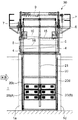
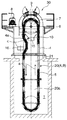
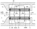
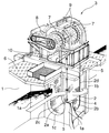
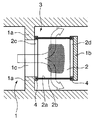
図1は、水路1の側面方向から見た除塵装置30の側面図、図2は水路1の上流方向から見た除塵装置30の正面図、図3は、水路1の上方向から見た除塵装置30の平面断面図である。
FIG. 1 is a side view of the
水路1内の中央位置に設置される除塵装置30は、図7および図8の従来の除塵装置3と基本的には同じ構成であるが、水路1内の上流側の隔壁1aの下流側に隔壁1dが形成されて、この上流側と下流側の隔壁1a,1dの間に回転スクリーン20が前開口20cを上流側に向けて、水路1に平行に配置されている。なお、隔壁1a,1dは、外部仕切り部材として機能するものであり、水路1と一体のコンクリート構造以外に、鋼板等を水路1に取付けたものであっても良い。
The
そして、各隔壁1a,1dに取付けられたガイド4(図7参照)により、回転スクリーン20の前後の開口端に取付けたエンドレスチェーン5が回転ガイドされるようになっている。
The
回転スクリーン20は、上部が水面上に突出するよう縦長楕円状に形成され、水面上の基板6で支持されたチェーンスプロケット7にエンドレスチェーン5の上部が噛み合わされ、電動モータ8でチェーンスプロケット7を駆動することにより、エンドレスチェーン5とともに回転スクリーン20が図2の矢印aの方向に回転されるようになる。
The
回転スクリーン20は、上流側と下流側とに2分されている。そして、上流側は、大型の塵芥(例えば10mm以上)を捕捉する粗目スクリーン20(A)に設定し、下流側は、小型の塵芥(例えば3mm以上)を捕捉する細目スクリーン20(B)に設定している。
The
上流側の粗目スクリーン20(A)と下流側の細目スクリーン20(B)との間は、仕切り壁(内部仕切り部材)21で仕切られている。この仕切り壁21には、上流側の粗目スクリーン20(A)の内面20aが目詰まりした非常時に、水流を下流側の細目スクリーン20(B)の方向に流すようにできる非常用ゲート(回転式のフラップ弁、バタフライ弁や引き上げ式ゲート等)を取付けることができる。また、スクリーン本体の上流側のろ過面に、上流側に向かって突出する突き出し通水管を並べ設けて、隣接する突き出し通水管に高低差を付けている除塵用立体スクリーン(特開2007−146461号公報参照。いわゆる突起ネット)を取付けることもできる。
The upstream coarse screen 20 (A) and the downstream fine screen 20 (B) are partitioned by a partition wall (internal partition member) 21. In this
そして、水路1内の流水は、矢印bで示すように、隔壁1aの間の中央通路1cを通って前開口20cから上流側の粗目スクリーン20(A)の内面20aに流入し、この内面(左右両内面の意味、以下同様)20aで大型の塵芥を捕捉しつつ外面(左右両外面の意味、以下同様)20bに通過して再び水路1内に戻る。次いで、下流側の細目スクリーン20(B)の外面20bで小型の塵芥を捕捉しつつ内面20aに通過して、後開口20dから隔壁1dの間の中央通路1cを通って水路1内に戻るようになる。
The flowing water in the
粗目スクリーン20(A)の内面20aで捕捉された大型の塵芥は、回転スクリーン20の回転によって水中から掻き上げられ、粗目スクリーン20(A)に対応する幅で設けられたスプレー装置9から噴射される水圧で吹き落されて、回転スクリーン20内のトラフ10に回収されるようになる。
A large dust trap captured by the
また、細目スクリーン20(B)の外面20bで捕捉された小型の塵芥は、回転スクリーン20の回転によって水中から掻き上げられ、細目スクリーン20(B)に対応する幅で設けられたスプレー装置15から噴射される水圧で吹き落されて、回転スクリーン20外のトラフ16に回収されるようになる。この場合、スプレー装置15とトラフ16との間に位置した細目スクリーン20(B)は、図2に符号cで示すように、一時的に斜め下向きに傾くように、回転スクリーン20、つまりエンドレスチェーン5をガイドするガイド部4aをガイド4に設けている。
In addition, the small dust trapped on the
前記のように除塵装置を構成すれば、水路1内の水流は、1台の除塵装置30の上流側の粗目スクリーン20(A)を通過してから下流側の細目スクリーン20(B)を通過するようになる。したがって、先ず粗目スクリーン20(A)で流水中の大型の塵埃が捕捉され、次いで細目スクリーン20(B)で流水中の小型の塵埃が捕捉されるようになる(2連結式スクリーン構造)。
If the dust removal device is configured as described above, the water flow in the
したがって、1台の除塵装置30の回転スクリーン20で、大型と小型の塵芥を目詰まりしないように合理的に順次捕捉できるから、2台の除塵装置を設置する場合と比べて、設置スペースが大きくならなくなる。
Therefore, since the
また、2台の除塵装置を設置する場合と比べて、水流の急拡や急縮の回数が少ないので、水理的に有利となる。 Further, compared with the case where two dust removing devices are installed, the number of rapid expansion and contraction of the water flow is small, which is hydraulically advantageous.
さらに、除塵装置30は1台であるので、除去した塵芥の処理が煩雑にならなくなる。さらにまた、粗目スクリーン20(A)と細目スクリーン20(B)とは、塵芥の大きさや量に応じて、目幅や面積比を自由に変更可能であるので、如何なる大きさの塵芥にも臨機応変に対応することができる。
Furthermore, since the
また、上流側の粗目スクリーン20(A)と下流側の細目スクリーン20(B)との間を仕切り壁21で仕切るだけで、上流側の粗目スクリーン20(A)の内面20aで大型の塵芥を捕捉しつつ流水を外面20bに通過(イン・アウト)させるとともに、下流側の細目スクリーン20(B)の外面20bで小型の塵芥を捕捉しつつ流水を内面20aに通過(アウト・イン)させることができる。
Further, by separating the upstream coarse screen 20 (A) and the downstream fine screen 20 (B) by the
さらに、ガイド部4aで、細目スクリーン20(B)が一時的に斜め下向きに傾くから、外面20bで捕捉した小型の塵芥が下方に落ちやすくなって、スプレー装置15から噴射される水圧で吹き落されて、回転スクリーン20外のトラフ16に回収されるので、小型の塵芥の除去が容易になる。
Furthermore, since the fine screen 20 (B) is inclined obliquely downward at the
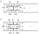
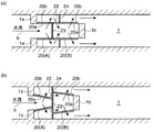
前記実施形態は、図4(a)のように、流水を粗目スクリーン20(A)の内面20aから外面20bに通過(イン・アウト)させ、細目スクリーン20(B)の外面20bから内面20aに通過(アウト・イン)させるものであった。
In the embodiment, as shown in FIG. 4A, running water is passed (in / out) from the
これに対して、図4(b)のように、上流側の粗目スクリーン20(A)と下流側の細目スクリーン20(B)との間の水路1を外部仕切り部材24で仕切って、流水を粗目スクリーン20(A)の外面20bから内面20aに通過(アウト・イン)させ、細目スクリーン20(B)の内面20aから外面20bに通過(イン・アウト)させるように構成することもできる。
On the other hand, as shown in FIG. 4 (b), the
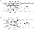
また、図5(a)のように、上流側の粗目スクリーン20(A)と下流側の細目スクリーン20(B)との間に開口部22を形成し、上流側の粗目スクリーン20(A)の下流端と開口部22の上流端との間を内部仕切り部材23で仕切るとともに、開口部22の下流端と下流側の細目スクリーン20(B)の上流端との間の水路1を外部仕切り部材24で仕切って、流水を粗目スクリーン20(A)の内面20aから外面20bに通過(イン・アウト)させるとともに、開口部22から細目スクリーン20(B)内に導入して、細目スクリーン20(B)の内面20aから外面20bに通過(イン・アウト)させるように構成することもできる。
Further, as shown in FIG. 5A, an
さらに、図5(b)のように、上流側の粗目スクリーン20(A)と下流側を細目スクリーン20(B)とを下流側向きに窄まったテーパ状に形成し、上流側の粗目スクリーン20(A)の下流端と下流側の細目スクリーン20(B)上流端との間に開口部22を形成し、上流側の粗目スクリーン20(A)の下流端を内部仕切り部材23で仕切るとともに、開口部22との間の水路1を外部仕切り部材24で仕切って、流水を粗目スクリーン20(A)の内面20aから外面20bに通過(イン・アウト)させるとともに、開口部22から細目スクリーン20(B)内に導入して、細目スクリーン20(B)の内面20aから外面20bに通過(イン・アウト)させるように構成することもできる。
Further, as shown in FIG. 5B, the upstream coarse screen 20 (A) and the downstream fine screen 20 (B) are formed in a tapered shape that is narrowed toward the downstream side, and the upstream coarse screen is formed. An
図5(a)(b)の構成であれば、回転スクリーン20の内面20a側で大型と小型の各塵芥を捕捉でき、スプレー装置9から噴射される水圧で回転スクリーン20内のトラフ10に吹き落して回収できるので、スプレー装置15や回転スクリーン20外のトラフ16が不要になり、塵芥の回収機構を単純化できるようになる。また、下流側の細目スクリーン20(B)を一時的に斜め下向きに傾くようにガイドするガイド部4aも不要になる。さらに、内面20a側だけで塵芥を捕捉するから、回転スクリーン20の構造が簡単になる。
5 (a) and 5 (b), large and small dust can be captured on the
図6(a)は図5(a)に対応し、図6(b)は図5(b)に対応する構成のものであり、水流の向きを変えたものである。なお、上流側の粗目スクリーン20(A)と下流側の細目スクリーン20(B)の位置も変えている。 6 (a) corresponds to FIG. 5 (a), and FIG. 6 (b) corresponds to FIG. 5 (b) in which the direction of the water flow is changed. The positions of the upstream coarse screen 20 (A) and the downstream fine screen 20 (B) are also changed.
そして、流水を粗目スクリーン20(A)の外面20bから内面20aに通過(アウト・イン)させるとともに、開口部22から細目スクリーン20(B)外に導出して、細目スクリーン20(B)の外面20bから内面20aに通過(アウト・イン)させるように構成することもできる。
Then, the running water is passed (out-in) from the
1 水路
4 ガイド
4a ガイド部
5 エンドレスチェーン
20 回転スクリーン
20(A) 粗目スクリーン
20(B) 細目スクリーン
20a 内面
20b 外面
20c 前開口
20d 後開口
21 内部仕切り部材
22 開口部
23 内部仕切り部材
24 外部仕切り部材
30 除塵装置
DESCRIPTION OF
Claims (6)
前記スクリーンは、上流側と下流側とに2分して、上流側を粗目スクリーンに設定し、下流側を細目スクリーンに設定して、
上流側の粗目スクリーンの内面若しくは外面のいずれか一面で大型の塵芥を捕捉しつつ流水を他面に通過させるとともに、下流側の細目スクリーンの内面若しくは外面のいずれか一面で小型の塵芥を捕捉しつつ流水を他面に通過させるようにしたことを特徴とする除塵装置。 An endless screen parallel to the water channel is provided at the center of the water channel, with the upstream side opened, and the flowing water is passed to the other surface while capturing dust on either the inner or outer surface of the screen. At the same time, it is a dust removing device that scavenges the captured dust from the water and removes it outside the water channel by rotating the screen,
The screen is divided into an upstream side and a downstream side, the upstream side is set as a coarse screen, the downstream side is set as a fine screen,
While catching large dust on either the inner or outer surface of the coarse screen on the upstream side, let the running water pass to the other surface, and catch small dust on either the inner or outer surface of the fine screen on the downstream side. A dust remover characterized in that running water is allowed to pass through to the other surface.
上流側の粗目スクリーンの内面で大型の塵芥を捕捉しつつ流水を外面に通過させるとともに、下流側の細目スクリーンの外面で小型の塵芥を捕捉しつつ流水を内面に通過させるようにしたことを特徴とする請求項1に記載の除塵装置。 Partitioning between the upstream coarse screen and the downstream fine screen with an internal partition member,
It is characterized by passing the flowing water to the outer surface while capturing large dust on the inner surface of the coarse screen on the upstream side, and passing the flowing water to the inner surface while capturing small dust on the outer surface of the fine screen on the downstream side. The dust removing apparatus according to claim 1.
上流側の粗目スクリーンの外面で大型の塵芥を捕捉しつつ流水を内面に通過させるとともに、下流側の細目スクリーンの内面で小型の塵芥を捕捉しつつ流水を外面に通過させるようにしたことを特徴とする請求項1に記載の除塵装置。 Partitioning the water channel between the upstream coarse screen and the downstream fine screen with an external partition member;
It is characterized by passing the flowing water to the inner surface while capturing large dust on the outer surface of the coarse screen on the upstream side, and passing the flowing water to the outer surface while capturing small dust on the inner surface of the fine screen on the downstream side. The dust removing apparatus according to claim 1.
上流側の粗目スクリーンの内面で大型の塵芥を捕捉しつつ流水を外面に通過させるとともに、開口部から下流側の細目スクリーン内に導入して、下流側の細目スクリーンの内面で小型の塵芥を捕捉しつつ流水を外面に通過させるようにしたことを特徴とする請求項1に記載の除塵装置。 An opening is formed between the upstream coarse screen and the downstream fine screen, and the upstream coarse screen and the downstream fine screen are partitioned by an internal partition member, and the opening and the downstream fine screen are separated. Partition the water channel between the screen with an external partition member,
While catching large dust on the inner surface of the coarse screen on the upstream side, passing running water to the outer surface and introducing it into the fine screen on the downstream side from the opening, catching small dust on the inner surface of the fine screen on the downstream side 2. The dust removing apparatus according to claim 1, wherein running water is passed through the outer surface.
上流側の粗目スクリーンの外面で大型の塵芥を捕捉しつつ流水を内面に通過させるとともに、開口部から下流側の細目スクリーン外に導出して、下流側の細目スクリーンの外面で小型の塵芥を捕捉しつつ流水を内面に通過させるようにしたことを特徴とする請求項1に記載の除塵装置。 An opening is formed between the upstream coarse screen and the downstream fine screen, and the upstream coarse screen and the downstream fine screen are partitioned by an internal partition member, and the opening and the downstream fine screen are separated. Partition the water channel between the screen with an external partition member,
While capturing large dust on the outer surface of the coarse screen on the upstream side, passing running water to the inner surface, leading out of the fine screen on the downstream side from the opening, and capturing small dust on the outer surface of the fine screen on the downstream side 2. The dust removing apparatus according to claim 1, wherein running water is allowed to pass through the inner surface.
Priority Applications (1)
| Application Number | Priority Date | Filing Date | Title |
|---|---|---|---|
| JP2008219217A JP5033738B2 (en) | 2008-08-28 | 2008-08-28 | Dust remover |
Applications Claiming Priority (1)
| Application Number | Priority Date | Filing Date | Title |
|---|---|---|---|
| JP2008219217A JP5033738B2 (en) | 2008-08-28 | 2008-08-28 | Dust remover |
Publications (2)
| Publication Number | Publication Date |
|---|---|
| JP2010053587A true JP2010053587A (en) | 2010-03-11 |
| JP5033738B2 JP5033738B2 (en) | 2012-09-26 |
Family
ID=42069782
Family Applications (1)
| Application Number | Title | Priority Date | Filing Date |
|---|---|---|---|
| JP2008219217A Active JP5033738B2 (en) | 2008-08-28 | 2008-08-28 | Dust remover |
Country Status (1)
| Country | Link |
|---|---|
| JP (1) | JP5033738B2 (en) |
Cited By (2)
| Publication number | Priority date | Publication date | Assignee | Title |
|---|---|---|---|---|
| CN102912767A (en) * | 2012-11-14 | 2013-02-06 | 江苏兆盛环保集团有限公司 | Vertical orifice plate grid trash-cleaning machine |
| JP2016011553A (en) * | 2014-06-30 | 2016-01-21 | 株式会社丸島アクアシステム | Rotary dust collector |
Families Citing this family (1)
| Publication number | Priority date | Publication date | Assignee | Title |
|---|---|---|---|---|
| CN106544847B (en) * | 2017-01-23 | 2017-08-25 | 舒燕 | A kind of design on fabric surface dust arrester |
-
2008
- 2008-08-28 JP JP2008219217A patent/JP5033738B2/en active Active
Cited By (2)
| Publication number | Priority date | Publication date | Assignee | Title |
|---|---|---|---|---|
| CN102912767A (en) * | 2012-11-14 | 2013-02-06 | 江苏兆盛环保集团有限公司 | Vertical orifice plate grid trash-cleaning machine |
| JP2016011553A (en) * | 2014-06-30 | 2016-01-21 | 株式会社丸島アクアシステム | Rotary dust collector |
Also Published As
| Publication number | Publication date |
|---|---|
| JP5033738B2 (en) | 2012-09-26 |
Similar Documents
| Publication | Publication Date | Title |
|---|---|---|
| JP5033738B2 (en) | Dust remover | |
| JP5507365B2 (en) | Dust remover | |
| JP2012036711A (en) | Road surface drainage treatment device | |
| JP6912653B2 (en) | Dust remover for cleaning gas | |
| JP2020528822A (en) | Dust remover for cleaning gas | |
| KR100762981B1 (en) | Nonpoint pollution decrease apparatus in link canal | |
| JP3125832B2 (en) | Contaminant removal device for two-way flowing water pipe | |
| JP7063801B2 (en) | Crusher | |
| JP4444874B2 (en) | Dust remover | |
| JP5809932B2 (en) | Dust remover | |
| JP3090568B2 (en) | Contaminant removal device for running water pipe | |
| KR20150000833A (en) | Strainer | |
| JPH07132205A (en) | Device for removing impurities in flow water pipe | |
| JP5586806B1 (en) | Foreign matter removing device and foreign matter collecting device | |
| JP2007098339A (en) | Treatment apparatus of cyclone type oil-mist collector | |
| JP5198589B2 (en) | Filtration device | |
| KR20070042500A (en) | Ball trap with safety-release gate | |
| JP3894227B1 (en) | Tunnel type jet water flow screen | |
| EP2937318B1 (en) | Cleaning apparatus for cleaning a fluid comprising a device for sedimentation and a device for adsorption | |
| JPH0418648Y2 (en) | ||
| US11951423B2 (en) | Systems and methods for screening | |
| KR102656812B1 (en) | Range hood | |
| KR102392835B1 (en) | A rotary dust separator that blocks the entry of foreign substances when at rest | |
| JP4058302B2 (en) | Dust remover | |
| JPS5826004Y2 (en) | Flowing water screen foreign matter ejector |
Legal Events
| Date | Code | Title | Description |
|---|---|---|---|
| A621 | Written request for application examination |
Free format text: JAPANESE INTERMEDIATE CODE: A621 Effective date: 20110610 |
|
| TRDD | Decision of grant or rejection written | ||
| A977 | Report on retrieval |
Free format text: JAPANESE INTERMEDIATE CODE: A971007 Effective date: 20120620 |
|
| A01 | Written decision to grant a patent or to grant a registration (utility model) |
Free format text: JAPANESE INTERMEDIATE CODE: A01 Effective date: 20120626 |
|
| A01 | Written decision to grant a patent or to grant a registration (utility model) |
Free format text: JAPANESE INTERMEDIATE CODE: A01 |
|
| A61 | First payment of annual fees (during grant procedure) |
Free format text: JAPANESE INTERMEDIATE CODE: A61 Effective date: 20120702 |
|
| R150 | Certificate of patent or registration of utility model |
Ref document number: 5033738 Country of ref document: JP Free format text: JAPANESE INTERMEDIATE CODE: R150 Free format text: JAPANESE INTERMEDIATE CODE: R150 |
|
| FPAY | Renewal fee payment (event date is renewal date of database) |
Free format text: PAYMENT UNTIL: 20150706 Year of fee payment: 3 |
|
| R250 | Receipt of annual fees |
Free format text: JAPANESE INTERMEDIATE CODE: R250 |
|
| R250 | Receipt of annual fees |
Free format text: JAPANESE INTERMEDIATE CODE: R250 |
|
| R250 | Receipt of annual fees |
Free format text: JAPANESE INTERMEDIATE CODE: R250 |
|
| R250 | Receipt of annual fees |
Free format text: JAPANESE INTERMEDIATE CODE: R250 |
|
| R250 | Receipt of annual fees |
Free format text: JAPANESE INTERMEDIATE CODE: R250 |