JP2010052640A - Electric power steering device - Google Patents
Electric power steering device Download PDFInfo
- Publication number
- JP2010052640A JP2010052640A JP2008221522A JP2008221522A JP2010052640A JP 2010052640 A JP2010052640 A JP 2010052640A JP 2008221522 A JP2008221522 A JP 2008221522A JP 2008221522 A JP2008221522 A JP 2008221522A JP 2010052640 A JP2010052640 A JP 2010052640A
- Authority
- JP
- Japan
- Prior art keywords
- motor
- steering
- assist
- electric power
- current
- Prior art date
- Legal status (The legal status is an assumption and is not a legal conclusion. Google has not performed a legal analysis and makes no representation as to the accuracy of the status listed.)
- Granted
Links
Images


Classifications
-
- B—PERFORMING OPERATIONS; TRANSPORTING
- B62—LAND VEHICLES FOR TRAVELLING OTHERWISE THAN ON RAILS
- B62D—MOTOR VEHICLES; TRAILERS
- B62D5/00—Power-assisted or power-driven steering
- B62D5/04—Power-assisted or power-driven steering electrical, e.g. using an electric servo-motor connected to, or forming part of, the steering gear
- B62D5/0457—Power-assisted or power-driven steering electrical, e.g. using an electric servo-motor connected to, or forming part of, the steering gear characterised by control features of the drive means as such
- B62D5/046—Controlling the motor
- B62D5/0469—End-of-stroke control
Abstract
Description
本発明は、モータのアシスト力により操舵を補助する電気式動力舵取装置に関するものである。 The present invention relates to an electric power steering apparatus that assists steering by an assist force of a motor.
従来より、モータのアシスト力により操舵を補助する電気式動力舵取装置として、下記特許文献1に示す、電動パワーステアリング装置が知られている。この電動パワーステアリング装置は、操舵中に転舵輪をこれ以上は切ることができない最大転舵状態(以下、据え切り状態ともいう)などの操舵時にアシストモータに流れるモータ電流が過電流状態になると、このアシストモータに供給する電流を小さくすることにより、アシストモータおよびその駆動回路に過剰な電流が長時間流れることを防止している。
ところで、アシストモータのトルクがコラムに伝達される、いわゆるコラムアシストタイプの電気式動力舵取装置においては、据え切り状態までステアリングホイールが切り込まれることにより高速で回転していたアシストモータが急停止すると、据え切り状態(端当て)直前のモータ回転速度に応じたアシストモータの慣性トルクにより、操舵輪とアシストモータとの間に配置されているインタミディエイトシャフト等の操舵系に過大な負荷が作用してしまう。 By the way, in the so-called column assist type electric power steering device in which the torque of the assist motor is transmitted to the column, the assist motor that has been rotating at a high speed is suddenly stopped by turning the steering wheel to the stationary state. Then, an excessive load is applied to a steering system such as an intermediate shaft disposed between the steering wheel and the assist motor due to the inertia torque of the assist motor according to the motor rotation speed immediately before the stationary state (end contact). Will work.
上述のように過電流状態になってからアシストモータへの供給電流を小さくした場合でも、既にアシストモータが急停止しているため、操舵系に作用する過大な負荷の発生を防止することができない。特に、電気式動力舵取装置の高出力化が求められる場合では、アシストモータの出力アップや減速機の高減速比化等の要因により、モータ慣性に起因するトルクにより、操舵系に作用する過大な負荷がさらに増大してしまう。また、インタミディエイトシャフト等の操舵系の強度を高くすると、製品重量の増加や製造コストの増加等の別の問題が発生してしまう。 Even when the supply current to the assist motor is reduced after the overcurrent state as described above, since the assist motor has already stopped suddenly, an excessive load acting on the steering system cannot be prevented. . In particular, when high output of the electric power steering device is required, excessive torque acting on the steering system due to torque caused by motor inertia due to factors such as increased output of the assist motor and high reduction ratio of the reducer Load increases further. Further, when the strength of a steering system such as an intermediate shaft is increased, other problems such as an increase in product weight and an increase in manufacturing cost occur.
本発明は、上述した課題を解決するためになされたものであり、その目的とするところは、据え切り時に操舵系に作用する負荷を抑制し得る電気式動力舵取装置を提供することにある。 The present invention has been made to solve the above-described problems, and an object of the present invention is to provide an electric power steering apparatus capable of suppressing a load acting on a steering system at the time of off-road. .
上記目的を達成するため、特許請求の範囲に記載の請求項1の電気式動力舵取装置では、車両のステアリングホイール(21)による操舵系(24)の操舵を補助可能なアシスト力を出力するアシストモータ(30)と、直流電源(Batt)から供給される電力をPWM制御することによりPWM信号のデューティ比に応じた電圧を前記アシストモータに出力する駆動回路(43)と、前記駆動回路を制御する制御手段(41)と、を備える電気式動力舵取装置(20)であって、前記アシストモータに流れるモータ電流(I)を検出するモータ電流検出手段(47)を有し、前記制御手段は、前記モータ電流が停車時において据え切り状態に近づいていると判断される所定の閾値(It)を超えると判定したとき前記デューティ比を小さくすることを技術的特徴とする。 In order to achieve the above object, the electric power steering apparatus according to claim 1 outputs an assist force capable of assisting steering of the steering system (24) by the steering wheel (21) of the vehicle. An assist motor (30), a drive circuit (43) that outputs a voltage corresponding to a duty ratio of a PWM signal to the assist motor by PWM control of electric power supplied from a DC power supply (Batt), and the drive circuit An electric power steering apparatus (20) comprising a control means (41) for controlling, and comprising a motor current detection means (47) for detecting a motor current (I) flowing through the assist motor, wherein the control The means reduces the duty ratio when it is determined that the motor current exceeds a predetermined threshold (It) that is determined to be approaching the stationary state when the vehicle is stopped. And technical, characterized in that.
請求項1の発明では、駆動回路により、直流電源から供給される電力をPWM制御することによりPWM信号のデューティ比に応じた電圧がアシストモータに出力される。この駆動回路を制御する制御手段は、モータ電流が停車時において据え切り状態に近づいていると判断される所定の閾値を超えると判定したとき上記デューティ比を小さくする。 According to the first aspect of the present invention, the drive circuit outputs the voltage corresponding to the duty ratio of the PWM signal to the assist motor by performing PWM control on the power supplied from the DC power supply. The control means for controlling the drive circuit reduces the duty ratio when it is determined that the motor current exceeds a predetermined threshold value that is determined to be approaching the stationary state when the vehicle is stopped.
ステアリングホイールの操舵により据え切り状態に近づくと、アシストに必要なトルクが大きくなることから、アシストモータに流れるモータ電流が増加する。そこで、停車時において据え切り状態に近づいていると判断されるときの電流値を所定の閾値と設定し、モータ電流がこの所定の閾値を超えるときにPWM制御におけるPWM信号のデューティ比を小さくする。これにより、駆動回路からアシストモータに出力される電圧が低下するため、据え切り時のアシストモータの回転速度を低下させるとともに操舵速度を下げることができる。
したがって、据え切り時にインタミディエイトシャフト等の操舵系に作用する負荷を抑制することができる。
As the steering wheel approaches the stationary state, the torque required for assist increases, so the motor current flowing through the assist motor increases. Therefore, the current value when it is determined that the vehicle is approaching the stationary state when the vehicle is stopped is set as a predetermined threshold value, and when the motor current exceeds the predetermined threshold value, the duty ratio of the PWM signal in the PWM control is reduced. . As a result, the voltage output from the drive circuit to the assist motor decreases, so that the rotation speed of the assist motor at the time of stationary can be decreased and the steering speed can be decreased.
Therefore, it is possible to suppress a load that acts on a steering system such as an intermediate shaft at the time of stationary.
請求項2の発明では、制御手段は、モータ電流が上記所定の閾値を超えるとの判定の際に当該所定の閾値を車両の車速に基づいて小さくする。停車時と比較して走行時ではアシストに必要なトルクが比較的小さくなることから、据え切り状態に近づいてもモータ電流が上述のように設定される所定の閾値を超えない場合には、アシストモータの回転速度を適切に低下させることができない。そこで、上述のように所定の閾値を車速に基づいて小さくすることにより、走行中であっても据え切り時のアシストモータの回転速度を適切に低下させることができる。
In the invention of
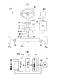
以下、本発明の一実施形態について図を参照して説明する。まず、本実施形態に係る電気式動力舵取装置の構成を図1(A),(B)に基づいて説明する。図1(A)は、本発明の実施形態に係る電気式動力舵取装置20の全体構成例を示す構成図であり、図1(B)は、ECU40等の電気的構成例を示す回路ブロック図である。図2は、ECU40による制御概要を示す制御ブロック図である。
Hereinafter, an embodiment of the present invention will be described with reference to the drawings. First, the configuration of the electric power steering apparatus according to the present embodiment will be described based on FIGS. 1 (A) and 1 (B). FIG. 1A is a configuration diagram showing an example of the overall configuration of an electric
図1(A)に示すように、電気式動力舵取装置20は、主に、ステアリングホイール21、ステアリング軸22、中間シャフト23、インタミディエイトシャフト24、ピニオン入力軸25、トルクセンサ26、減速機27、ラックアンドピニオン28、ロッド29、アシストモータ30、ECU40等から構成されるコラム式の電気式動力舵取装置である。
As shown in FIG. 1A, the electric
ステアリングホイール21には、ステアリング軸22の一端側が接続されており、このステアリング軸22の他端側にはトルクセンサ26の入力側が接続されている。またこのトルクセンサ26の出力側には、中間シャフト23の一端側が接続されている。トルクセンサ26は、図略のトーションバーとこのトーションバーを挟むようにトーションバーの両端に取り付けられた2つのレゾルバとからなり、トーションバーの一端側を入力、他端側を出力とする入出力間で生じるトーションバーの捻れ量等を当該2つのレゾルバにより検出することで、ステアリングホイール21による操舵トルクTを検出し得るように構成されている。
One end side of the
トルクセンサ26の出力側に接続される中間シャフト23の途中には、減速機27が連結されており、アシストモータ30から出力されるアシスト力をこの減速機27を介して中間シャフト23に伝達し得るように構成されている。
A
即ち、図面には示されていないが、動力伝達機構としての減速機27は、アシストモータ30の出力軸に取り付けられたモータギヤと減速機27の減速ギヤとが互いに噛合可能に構成されており、アシストモータ30の出力軸が回転すると所定の減速比で減速機27の減速ギヤが回転することで、アシストモータ30による駆動力(アシスト力)を中間シャフト23に伝達可能にしている。
That is, although not shown in the drawing, the speed reducer 27 as a power transmission mechanism is configured such that the motor gear attached to the output shaft of the
この中間シャフト23の他端側とピニオン入力軸25の一端側との間には、それぞれユニバーサルジョイント24a等を介してインタミディエイトシャフト24が配置されており、このインタミディエイトシャフト24は、中間シャフト23の回転をピニオン入力軸25の回転として伝達する役割を果たす。
Between the other end side of the
ピニオン入力軸25の他端側には、ラックアンドピニオン28を構成する図略のラック軸のラック溝に噛合可能なピニオンギヤが形成されている。このラックアンドピニオン28では、ピニオン入力軸25の回転運動をラック軸の直線運動に変換可能にしており、またこのラック軸の両端にはロッド29が連結され、さらにこのロッド29の端部には図略のナックル等を介して操舵輪FR、FLが連結されている。これにより、ピニオン入力軸25が回転すると、ラックアンドピニオン28、ロッド29等を介して操舵輪FR、FLの実舵角を変化させることができるので、ピニオン入力軸25の回転量および回転方向に従った操舵輪FR、FLの操舵を可能にしている。
On the other end side of the
次に、アシストモータ30の駆動制御を担うECU40の電気的構成を図1(B)に基づいて説明する。図1(B)に示すように、ECU40は、主に、MPU41、インターフェイスI/F42、モータ駆動回路43等により構成されており、MPU41を中心に入出力バスを介してインターフェイスI/F42やモータ駆動回路43等が接続されている。なお、図1(B)に示す符号47は、アシストモータ30に実際に流れるモータ電流値Iを検出し得る電流センサ47であり、この電流センサ47により検出されたモータ電流値Iに関するセンサ情報は、モータ電流値信号としてインターフェイスI/F42を介してMPU41に入力され得るように構成されている。また、MPU41には、車両の車速Vを検出するための車速センサ50がインターフェイスI/F42を介して電気的に接続されている(図1(A),図2参照)。
Next, the electrical configuration of the
MPU41は、例えば、マイコン、半導体メモリ装置(ROM、RAM、EEPROM等)等から構成されており、電気式動力舵取装置20の基本的なアシストモータ制御を所定のコンピュータプログラムにより実行する機能を有するものである。
The MPU 41 is composed of, for example, a microcomputer, a semiconductor memory device (ROM, RAM, EEPROM, etc.), etc., and has a function of executing basic assist motor control of the electric
インターフェイスI/F42は、上述したトルクセンサ26、電流センサ47あるいは車速センサ50等から入力される各種センサ信号を、A/D変換器等を介してMPU41の所定ポートに入力する機能等を有するものである。
The interface I /
モータ駆動回路43は、直流電源Battから供給される電力を制御可能な3相交流電力に変換する機能を有するもので、PWM回路とスイッチング回路等から構成されている。PWM回路は、MPU41から出力される所定のデューティ比のPWM信号に基づいて、各相ごとにスイッチング回路をONまたはOFFし得るスイッチング信号を発生するパルス変調回路で、発生させたスイッチング信号はスイッチング回路に出力される。スイッチング回路を構成する各スイッチング素子には、例えば高速スイッチング用のMOSFETが用いられており、各相ごとに、直流電源Batt とアースとの間に2個1組のスイッチング素子がトーテムポール接続されている。
The
これにより、図2に示すECU40では、後述するアシスト力の制御処理により、トルクセンサ26の操舵トルクTや電流センサ47のモータ電流値Iあるいは車速センサ50の車速Vに基づいて、操舵状態に適したアシストトルクをアシストモータ30に発生させ得るため、電気式動力舵取装置20では、ステアリングホイール21による運転者の操舵を補助可能にしている。
2 is suitable for the steering state based on the steering torque T of the
次に、以上のように構成されるECU40によるアシスト力の制御処理の概要を図2に基づいて説明する。
ECU40のMPU41により行われるアシスト力の制御は、位相補償部41a、電流指令値演算部41b、デューティ制限値設定部41cおよびPWM演算部41dにより構成されている。
Next, the outline of the assist force control process by the
The assist force control performed by the
まずトルクセンサ26により検出された操舵トルクTは、インターフェイスI/F42を介してMPU41に入力されると、電気式動力舵取装置20の安定性を高めるために位相補償部41aにより位相補償処理が行われた後、電流指令値演算部41bに出力される。
First, when the steering torque T detected by the
位相補償された操舵トルクTが入力される電流指令値演算部41bには、車速センサ50により検出された車速Vも入力されるので、電流指令値演算部41bでは、MPU41のメモリに予め記憶されている図略のアシストマップに基づいて、操舵トルクTおよび車速Vに対応した電流目標値Iqmを演算する。この電流指令値演算部41bでは、操舵トルクTのみならず車速Vにも対応した電流目標値Iqmの演算を行っているので、例えば、車速Vが小さいときには大きなアシスト力を出力するように、また車速Vが大きいときには小さなアシスト力を出力するように、電流目標値Iqmを演算する、いわゆる車速依存型の電流指令値演算が行われている。そして、電流指令値演算部41bから出力される電流目標値Iqmと、電流センサ47により検出されるモータ電流値Iとの差に基づくモータ電流指令値Iq*がPWM演算部41dに出力される。
Since the vehicle speed V detected by the
デューティ制限値設定部41cでは、後述するように、モータ電流値Iおよび車速Vに応じてデューティ制限値Gdを設定するとともに、このデューティ制限値GdをPWM演算部41dに出力する。このようなデューティ制限値Gdの設定処理の流れについては後述する図3に示すフローチャートにて詳細に説明する。
As described later, the duty limit
PWM演算部41dでは、モータ電流指令値Iq*に応じた電圧指令値Vq*を演算して、PWM演算された所定のデューティ比のPWM信号がモータ駆動回路43に出力される。このとき、モータ駆動回路43の低電圧側のスイッチング素子に対するPWM信号のデューティ比は、高電圧側のスイッチング素子のデューティ比に対して上記デューティ制限値Gdが乗算された値に調整されている。
The
モータ駆動回路43では、PWM演算部41dから出力される各相のPWM信号に基づいて、各相ごとにスイッチング回路をONまたはOFFする。これにより、モータ駆動回路43は、直流電源Battから供給される直流電力を予定する3相交流電力に変換してアシストモータ30を駆動制御することでアシストモータ30による適正なアシスト力を発生させることが可能となる。
In the
特に、デューティ制限値Gdが1未満に設定される場合には、低電圧側のスイッチング素子におけるデューティ比が制限されて低下することとなり、アシストモータ30に供給される電圧が小さくなることから、アシストモータ30の回転速度が小さくなる。
In particular, when the duty limit value Gd is set to less than 1, the duty ratio in the switching element on the low voltage side is limited and decreases, and the voltage supplied to the assist
ところで、据え切り状態までステアリングホイール21が切り込まれることにより高速で回転していたアシストモータ30が急停止すると、アシストモータ30の慣性トルクに応じた回転力が操舵輪FR、FLとアシストモータ30との間に配置されているインタミディエイトシャフト24等の操舵系に過大な負荷として作用してしまう。
By the way, when the
ステアリングホイール21の操舵により据え切り状態に近づくと、操舵に応じてラック軸を回転させるための力(以下、ラック軸力Fともいう)が大きくなることから、アシストに必要なトルクが大きくなり、アシストモータ30に流れるモータ電流値Iが増加する。そこで、停車時において据え切り状態に近づいていると判断されるときの電流値を所定の電流閾値Itと設定し、モータ電流値Iがこの電流閾値Itを超えるときに、1未満に設定されるデューティ制限値Gdを乗算することで低下させたデューティ比のPWM信号を出力してPWM制御を行う。これにより、モータ駆動回路43からアシストモータ30に出力される電圧が低下するため、据え切り時のアシストモータ30の回転速度を低下させることができる。
As the
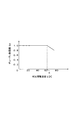
以下、デューティ制限値Gdを設定する処理の流れを、図3に示すフローチャートを用いて詳細に説明する。図3は、ECU40によるデューティ制限値設定処理の流れを示すフローチャートである。図4は、デューティ制限値設定処理に用いられる車速−軸力補正電流値マップの一例を示す説明図である。図5は、車速Vとラックエンド軸力Fmとの関係を示す説明図である。図6は、デューティ制限値設定処理に用いられる判定用電流値−デューティ制限値マップの一例を示す説明図である。図7は、ラック軸力Fと操舵速度ωとの関係を示す説明図である。
Hereinafter, the flow of processing for setting the duty limit value Gd will be described in detail with reference to the flowchart shown in FIG. FIG. 3 is a flowchart showing the flow of the duty limit value setting process by the
まず、図3のステップS101において、軸力補正電流値Inの設定処理がなされる。この処理では、図4の車速−軸力補正電流値マップに基づいて、車速Vに応じた軸力補正電流値Inが設定される。このように軸力補正電流値Inを設定する理由について以下に説明する。 First, in step S101 of FIG. 3, the setting process of the axial force correction current value In is performed. In this process, the axial force correction current value In corresponding to the vehicle speed V is set based on the vehicle speed-axial force correction current value map of FIG. The reason for setting the axial force correction current value In in this way will be described below.
図5に示すように、停車時(車速V=0km/h)に対して走行中では据え切り時のラック軸力(以下、ラックエンド軸力Fmともいう)が減少する。このため、停車時と比較して走行時では操舵のアシストに必要なトルクが比較的小さくなることから、走行時のモータ電流値Iは、停車時に比べて小さくなる。その結果、後述するように据え切り状態に近づいてもモータ電流値Iが上述した電流閾値Itを超えない場合には、アシストモータ30の回転速度を適切に低下させることができない。
As shown in FIG. 5, the rack axial force at the time of stationary (hereinafter also referred to as rack end axial force Fm) decreases during traveling with respect to the stop (vehicle speed V = 0 km / h). For this reason, since the torque required for steering assist is relatively small during traveling as compared to when the vehicle is stopped, the motor current value I during traveling is smaller than when the vehicle is stopped. As a result, if the motor current value I does not exceed the above-described current threshold It even when approaching the stationary state as will be described later, the rotational speed of the
そこで、停車中のラックエンド軸力Fmと走行中のラックエンド軸力Fmとの軸力差をなくすためのアシストモータ30に供給する電流(以下、軸力補正電流値Inともいう)を車速Vに応じて求めるとともに、この軸力補正電流値Inと車速Vとの関係を図4に示す車速−軸力補正電流値マップとして予め設定して記憶しておく。なお、本実施形態においては、停車時のラックエンド軸力Fmは、例えば、7kNに設定されている。
Accordingly, a current (hereinafter also referred to as an axial force correction current value In) supplied to the assist
そして、車速Vに基づいて車速−軸力補正電流値マップから軸力補正電流値Inを求め、後述するように、この軸力補正電流値Inをモータ電流値Iに加算した判定用電流値Ijと上記電流閾値Itとを比較する。これにより、走行時には上記電流閾値Itをモータ電流値Iに対して相対的に低下させることで、走行中であっても据え切り時のアシストモータ30の回転速度を適切に低下させることができる。
Then, an axial force correction current value In is obtained from the vehicle speed-axial force correction current value map based on the vehicle speed V, and a determination current value Ij obtained by adding the axial force correction current value In to the motor current value I as will be described later. And the current threshold It. Thus, by reducing the current threshold It relatively with respect to the motor current value I during traveling, the rotational speed of the
ステップS101にて軸力補正電流値Inが設定されると、ステップS103において、電流センサ47にて検出されたモータ電流値Iに軸力補正電流値Inを加算して上述した判定用電流値Ijを算出する。
When the axial force correction current value In is set in step S101, the determination current value Ij described above is obtained by adding the axial force correction current value In to the motor current value I detected by the
次に、ステップS105において、デューティ制限値Gdの設定処理がなされる。この処理では、図6の判定用電流値−デューティ制限値マップに基づいて、判定用電流値Ijに応じたデューティ制限値Gdが設定される。このようにデューティ制限値Gdを設定する理由について以下に説明する。 Next, in step S105, the duty limit value Gd is set. In this process, the duty limit value Gd corresponding to the determination current value Ij is set based on the determination current value-duty limit value map of FIG. The reason for setting the duty limit value Gd in this way will be described below.
図7に示すように、停車時において、ステアリングホイール21の操舵により据え切り状態に近づくと、操舵のアシストに必要なトルクが増加するためにラック軸力Fが増加する一方で、ステアリングホイール21を操舵する際の操舵速度ωが低下する。ラック軸力Fがラックエンド軸力Fmに対して十分小さい場合には、据え切り状態になるおそれがないので、操舵速度ωを調整する必要はない。しかしながら、ステアリングホイール21の操舵に応じてラック軸力Fが増加して据え切り状態に近づいていると判断される場合には、据え切り状態時において操舵系に作用する過大な負荷の発生を防止するために、操舵速度ωを小さくする必要がある。一方、例えば、据え切り直前状態にて少なくとも2rad/secの操舵速度ωが必要などの最低操舵速度が要求されている場合には、操舵速度ωを単純に小さくすることができない。
As shown in FIG. 7, when the vehicle stops, when the
そこで、据え切り状態に近づいていると判断されるときのラック軸力Fを高ラック軸力Faとすると、ラック軸力Fが高ラック軸力Faを超えたときに操舵速度ωを下げるために、アシストモータ30の回転速度を低下させることにより、操舵速度ωを低下させる(図7参照)。なお、本実施形態においては、高ラック軸力Faは、例えば、6kNに設定されている。 Therefore, if the rack axial force F when it is determined that the vehicle is approaching the stationary state is the high rack axial force Fa, the steering speed ω is decreased when the rack axial force F exceeds the high rack axial force Fa. Then, the steering speed ω is reduced by reducing the rotational speed of the assist motor 30 (see FIG. 7). In the present embodiment, the high rack axial force Fa is set to 6 kN, for example.
具体的には、停車時においてラック軸力Fが高ラック軸力Faに等しくなるときのモータ電流値が上述した電流閾値Itとなるので、図6に示すように、判定用電流値Ijが電流閾値It以下である判定されるとデューティ制限値Gdが1に設定される。また、判定用電流値Ijが電流閾値Itを超えると判定されるとアシストモータ30の回転速度を低下させて操舵速度ωを低下させるためにデューティ制限値Gdが1から所定の低下度合で小さくなるように設定される。なお、本実施形態においては、電流閾値Itは、例えば、60Aに設定されている。
Specifically, since the motor current value when the rack axial force F becomes equal to the high rack axial force Fa when the vehicle stops is the above-described current threshold It, as shown in FIG. When it is determined that the threshold is It or less, the duty limit value Gd is set to 1. When it is determined that the determination current value Ij exceeds the current threshold It, the duty limit value Gd is decreased from 1 to a predetermined decrease degree in order to decrease the rotation speed of the
特に、上述したように据え切り直前状態等で最低操舵速度が要求されている場合には、この最低操舵速度に対応可能なデューティ制限値Gdの値を予め計算等で求め、据え切り直前状態等でこの値以上になるように上記所定の低下度合を調整する。 In particular, when the minimum steering speed is requested in the state immediately before the stationary state as described above, the value of the duty limit value Gd that can correspond to the minimum steering speed is calculated in advance, and the state immediately before the stationary state, etc. The predetermined degree of decrease is adjusted so as to be equal to or greater than this value.
上述したデューティ制限値設定処理によりデューティ制限値Gdが設定されると、モータ駆動回路43の高電圧側のスイッチング素子には所定のデューティ比のPWM信号が出力され、低電圧側のスイッチング素子には上記所定のデューティ比にデューティ制限値Gdを乗算したデューティ比のPWM信号が出力される。
When the duty limit value Gd is set by the duty limit value setting process described above, a PWM signal having a predetermined duty ratio is output to the switching element on the high voltage side of the
これにより、据え切り状態に近づいていると判断される場合には、デューティ制限値Gdが1未満に設定されて低電圧側のスイッチング素子におけるデューティ比が制限されて低下することとなり、アシストモータ30に供給される電圧が小さくなる。このため、据え切り時のアシストモータ30の回転速度が低下し操舵速度ωも同様に低下する。その結果、据え切り状態におけるインタミディエイトシャフト24等の操舵系に作用する負荷を抑制することができ、据え切り操舵に起因する操舵系の破損を防止することができる。
As a result, when it is determined that the stationary state is approaching, the duty limit value Gd is set to be less than 1 and the duty ratio in the switching element on the low voltage side is limited and decreases, and the
以上説明したように、本実施形態に係る電気式動力舵取装置20では、モータ駆動回路43により、直流電源Battから供給される電力をPWM制御することによりPWM信号のデューティ比に応じた電圧がアシストモータ30に出力される。このモータ駆動回路43を制御するMPU41は、モータ電流Iに軸力補正電流値Inを加算した判定用電流値Ijが電流閾値Itを超えると判定したとき、モータ駆動回路43の低電圧側のスイッチング素子におけるデューティ比をデューティ制限値Gdの乗算により小さくし、この判定の際に上記軸力補正電流値Inを当該車両の車速Vに基づいて大きくする。
As described above, in the electric
これにより、モータ駆動回路43からアシストモータ30に出力される電圧が低下するため、据え切り時のアシストモータ30の回転速度を低下させるとともに操舵速度ωを下げることができる。
したがって、据え切り時にインタミディエイトシャフト24等の操舵系に作用する負荷を抑制することができる。
As a result, the voltage output from the
Therefore, it is possible to suppress a load acting on the steering system such as the
また、本実施形態に係る電気式動力舵取装置20では、車速Vに応じて設定される軸力補正電流値Inをモータ電流値Iに加算した判定用電流値Ijと上記電流閾値Itとを比較していることから、走行時には上記電流閾値Itをモータ電流値Iに対して相対的に低下させているので、走行中であっても据え切り時のアシストモータ30の回転速度を適切に低下させることができる。
In the electric
なお、本発明は上記実施形態に限定されるものではなく、以下のように具体化してもよく、その場合でも、上記実施形態と同等の作用・効果が得られる。
(1)図6の判定用電流値−デューティ制限値マップにおいて、判定用電流値Ijが電流閾値Itを超えた場合に、デューティ制限値Gdは1から上記所定の低下度合で小さくなるように設定されることに限らず、例えば、1から段階的に小さくなるように設定されてもよいし、1より小さい値に等しくなるように設定されてもよい。
In addition, this invention is not limited to the said embodiment, You may actualize as follows, and even in that case, an effect | action and effect equivalent to the said embodiment are acquired.
(1) In the determination current value-duty limit value map of FIG. 6, when the determination current value Ij exceeds the current threshold It, the duty limit value Gd is set so as to decrease from 1 at the predetermined decrease degree. For example, it may be set so as to decrease stepwise from 1 or may be set to be equal to a value smaller than 1.
(2)PWM演算部41dでは、デューティ制限値Gdを、低電圧側のスイッチング素子におけるデューティ比だけでなく、高電圧側のスイッチング素子におけるデューティ比にも乗算することにより、低電圧側および高電圧側の双方のスイッチング素子におけるデューティ比を制限して低下するようにしてもよい。このようにしても、アシストモータ30に供給される電圧が小さくなることから、据え切り時にアシストモータ30の回転速度を小さくすることができる。
(2) The
20…電気式動力舵取装置
21…ステアリングホイール
24…インタミディエイトシャフト(操舵系)
30…アシストモータ
40…ECU
41…MPU(制御手段)
43…モータ駆動回路(駆動回路)
47…電流センサ(モータ電流検出手段)
50…車速センサ(車速検出手段)
Batt…直流電源
F…ラック軸力
Fm…ラックエンド軸力
Gd…デューティ制限値
I…モータ電流値
Ij…判定用電流値
In…軸力補正電流値
It…電流閾値(所定の閾値)
T…操舵トルク
V…車速
ω…操舵速度
20 ... Electric
30 ... Assist
41 ... MPU (control means)
43 ... Motor drive circuit (drive circuit)
47 ... Current sensor (motor current detection means)
50. Vehicle speed sensor (vehicle speed detection means)
Batt ... DC power supply F ... Rack axial force Fm ... Rack end axial force Gd ... Duty limit value I ... Motor current value Ij ... Determination current value In ... Axial force correction current value It ... Current threshold (predetermined threshold)
T ... steering torque V ... vehicle speed ω ... steering speed
Claims (2)
直流電源から供給される電力をPWM制御することによりPWM信号のデューティ比に応じた電圧を前記アシストモータに出力する駆動回路と、
前記駆動回路を制御する制御手段と、
を備える電気式動力舵取装置であって、
前記アシストモータに流れるモータ電流を検出するモータ電流検出手段を有し、
前記制御手段は、前記モータ電流が停車時において据え切り状態に近づいていると判断される所定の閾値を超えると判定したとき前記デューティ比を小さくすることを特徴とする電気式動力舵取装置。 An assist motor that outputs an assist force capable of assisting steering of the steering system by the steering wheel of the vehicle;
A drive circuit that outputs a voltage corresponding to a duty ratio of a PWM signal to the assist motor by PWM control of power supplied from a DC power supply;
Control means for controlling the drive circuit;
An electric power steering apparatus comprising:
Motor current detecting means for detecting a motor current flowing through the assist motor;
The electric power steering apparatus according to claim 1, wherein the control means reduces the duty ratio when it is determined that the motor current exceeds a predetermined threshold value that is determined to be approaching a stationary state when the vehicle is stopped.
前記制御手段は、前記モータ電流が前記所定の閾値を超えるとの判定の際に当該所定の閾値を前記車速に基づいて小さくすることを特徴とする請求項1に記載の電気式動力舵取装置。 Vehicle speed detecting means for detecting the vehicle speed of the vehicle,
The electric power steering apparatus according to claim 1, wherein the control means reduces the predetermined threshold value based on the vehicle speed when determining that the motor current exceeds the predetermined threshold value. .
Priority Applications (3)
| Application Number | Priority Date | Filing Date | Title |
|---|---|---|---|
| JP2008221522A JP5217794B2 (en) | 2008-08-29 | 2008-08-29 | Electric power steering device |
| US12/461,759 US20100057300A1 (en) | 2008-08-29 | 2009-08-24 | Electric power steering apparatus |
| EP09168831.7A EP2159133B1 (en) | 2008-08-29 | 2009-08-27 | Electric power steering apparatus |
Applications Claiming Priority (1)
| Application Number | Priority Date | Filing Date | Title |
|---|---|---|---|
| JP2008221522A JP5217794B2 (en) | 2008-08-29 | 2008-08-29 | Electric power steering device |
Publications (2)
| Publication Number | Publication Date |
|---|---|
| JP2010052640A true JP2010052640A (en) | 2010-03-11 |
| JP5217794B2 JP5217794B2 (en) | 2013-06-19 |
Family
ID=41426972
Family Applications (1)
| Application Number | Title | Priority Date | Filing Date |
|---|---|---|---|
| JP2008221522A Expired - Fee Related JP5217794B2 (en) | 2008-08-29 | 2008-08-29 | Electric power steering device |
Country Status (3)
| Country | Link |
|---|---|
| US (1) | US20100057300A1 (en) |
| EP (1) | EP2159133B1 (en) |
| JP (1) | JP5217794B2 (en) |
Cited By (4)
| Publication number | Priority date | Publication date | Assignee | Title |
|---|---|---|---|---|
| WO2011111863A1 (en) | 2010-03-10 | 2011-09-15 | Ricoh Company, Ltd. | Toner container and image forming device |
| JP6056975B2 (en) * | 2013-07-26 | 2017-01-11 | 日産自動車株式会社 | Vehicle steering control device and vehicle steering control method |
| KR20180097345A (en) * | 2017-02-23 | 2018-08-31 | 주식회사 엘지화학 | Apratus and method for protecting battery protection cirtuit |
| CN111619658A (en) * | 2019-02-27 | 2020-09-04 | 操纵技术Ip控股公司 | Steering system with damping-related scaling to reduce wheel imbalance-induced vibrations |
Families Citing this family (17)
| Publication number | Priority date | Publication date | Assignee | Title |
|---|---|---|---|---|
| JP5534292B2 (en) * | 2008-06-30 | 2014-06-25 | 株式会社ジェイテクト | Vehicle steering system |
| JP5376215B2 (en) * | 2009-01-30 | 2013-12-25 | 株式会社ジェイテクト | Motor control device |
| JP5495018B2 (en) | 2009-03-12 | 2014-05-21 | 株式会社ジェイテクト | Motor control device |
| JP5561516B2 (en) * | 2009-07-06 | 2014-07-30 | 株式会社ジェイテクト | Motor control device and vehicle steering device |
| JP2011031713A (en) * | 2009-07-31 | 2011-02-17 | Jtekt Corp | Electric power steering system |
| JP5532295B2 (en) * | 2009-11-12 | 2014-06-25 | 株式会社ジェイテクト | Motor control device and vehicle steering device |
| JP5440846B2 (en) * | 2009-11-16 | 2014-03-12 | 株式会社ジェイテクト | Motor control device and vehicle steering device |
| JP5614583B2 (en) * | 2009-11-17 | 2014-10-29 | 株式会社ジェイテクト | Motor control device and vehicle steering device |
| CN102939708B (en) * | 2010-06-08 | 2015-12-16 | 松下电器产业株式会社 | Motor drive, brushless motor and electric motor drive method |
| JP5692569B2 (en) | 2010-08-23 | 2015-04-01 | 株式会社ジェイテクト | Vehicle steering system |
| JP2012131471A (en) * | 2010-11-29 | 2012-07-12 | Honda Motor Co Ltd | Electric steering system |
| WO2013123208A1 (en) * | 2012-02-14 | 2013-08-22 | Marine Canada Acquisition, Inc. | A steering system for a marine vessel |
| JP6198725B2 (en) * | 2012-05-11 | 2017-09-20 | 三菱電機株式会社 | Electric power steering device |
| CN105320121B (en) * | 2014-07-16 | 2018-02-23 | 联创汽车电子有限公司 | Electric power steering safety monitoring system |
| JP2016172459A (en) * | 2015-03-16 | 2016-09-29 | 株式会社ジェイテクト | Steering device |
| FR3036899B1 (en) * | 2015-05-26 | 2018-07-27 | Faurecia Sieges D'automobile | CONTROL OF A SEAT ADJUSTMENT MOTOR FOR A MOTOR VEHICLE |
| JP7130609B2 (en) | 2019-07-31 | 2022-09-05 | 株式会社クボタ | combine |
Citations (4)
| Publication number | Priority date | Publication date | Assignee | Title |
|---|---|---|---|---|
| JPH05254454A (en) * | 1992-03-16 | 1993-10-05 | Nippon Seiko Kk | Motor-operated power steering control device |
| JPH11240459A (en) * | 1998-02-24 | 1999-09-07 | Nippon Seiko Kk | Control unit for electric power steering system |
| JP2001151135A (en) * | 1999-11-22 | 2001-06-05 | Omron Corp | Motor-driven power steering device |
| JP2001322555A (en) * | 2000-05-17 | 2001-11-20 | Toyota Motor Corp | Vehicular electric power steering device |
Family Cites Families (12)
| Publication number | Priority date | Publication date | Assignee | Title |
|---|---|---|---|---|
| GB9606802D0 (en) * | 1996-03-30 | 1996-06-05 | Lucas Ind Plc | Current limiter for an EPAS system |
| JP3603736B2 (en) | 2000-03-29 | 2004-12-22 | 三菱電機株式会社 | Electric power steering control device |
| DE10128068B4 (en) | 2001-06-09 | 2006-05-04 | Adam Opel Ag | Electric motor powered power steering with overload protection |
| JP2004203366A (en) * | 2002-10-31 | 2004-07-22 | Koyo Seiko Co Ltd | Electric power steering device |
| JP4193113B2 (en) * | 2003-02-27 | 2008-12-10 | 株式会社ジェイテクト | Electric power steering device |
| JP4411514B2 (en) * | 2003-09-08 | 2010-02-10 | 株式会社ジェイテクト | Electric power steering device |
| JP4539217B2 (en) * | 2004-07-30 | 2010-09-08 | 日本精工株式会社 | Electric power steering device |
| JP4984110B2 (en) * | 2006-01-12 | 2012-07-25 | 株式会社ジェイテクト | Electric power steering device |
| JP4895091B2 (en) * | 2006-01-16 | 2012-03-14 | 株式会社ジェイテクト | Electric power steering device |
| JP4449918B2 (en) * | 2006-02-15 | 2010-04-14 | トヨタ自動車株式会社 | Electric power steering device |
| EP1864886A2 (en) * | 2006-06-07 | 2007-12-12 | NSK Ltd. | Electric power steering apparatus |
| JP4475434B2 (en) * | 2007-03-12 | 2010-06-09 | 三菱電機株式会社 | Electric power steering control device |
-
2008
- 2008-08-29 JP JP2008221522A patent/JP5217794B2/en not_active Expired - Fee Related
-
2009
- 2009-08-24 US US12/461,759 patent/US20100057300A1/en not_active Abandoned
- 2009-08-27 EP EP09168831.7A patent/EP2159133B1/en not_active Not-in-force
Patent Citations (4)
| Publication number | Priority date | Publication date | Assignee | Title |
|---|---|---|---|---|
| JPH05254454A (en) * | 1992-03-16 | 1993-10-05 | Nippon Seiko Kk | Motor-operated power steering control device |
| JPH11240459A (en) * | 1998-02-24 | 1999-09-07 | Nippon Seiko Kk | Control unit for electric power steering system |
| JP2001151135A (en) * | 1999-11-22 | 2001-06-05 | Omron Corp | Motor-driven power steering device |
| JP2001322555A (en) * | 2000-05-17 | 2001-11-20 | Toyota Motor Corp | Vehicular electric power steering device |
Cited By (8)
| Publication number | Priority date | Publication date | Assignee | Title |
|---|---|---|---|---|
| WO2011111863A1 (en) | 2010-03-10 | 2011-09-15 | Ricoh Company, Ltd. | Toner container and image forming device |
| EP3620863A1 (en) | 2010-03-10 | 2020-03-11 | Ricoh Company, Ltd. | Toner container and image forming device |
| JP6056975B2 (en) * | 2013-07-26 | 2017-01-11 | 日産自動車株式会社 | Vehicle steering control device and vehicle steering control method |
| KR20180097345A (en) * | 2017-02-23 | 2018-08-31 | 주식회사 엘지화학 | Apratus and method for protecting battery protection cirtuit |
| KR102252176B1 (en) | 2017-02-23 | 2021-05-14 | 주식회사 엘지화학 | Apratus and method for protecting battery protection cirtuit |
| CN111619658A (en) * | 2019-02-27 | 2020-09-04 | 操纵技术Ip控股公司 | Steering system with damping-related scaling to reduce wheel imbalance-induced vibrations |
| CN111619658B (en) * | 2019-02-27 | 2022-06-17 | 操纵技术Ip控股公司 | Steering system with damping-related scaling to reduce wheel imbalance-induced vibrations |
| US11511796B2 (en) | 2019-02-27 | 2022-11-29 | Steering Solutions Ip Holding Corporation | Steering system with damping dependent scaling for wheel imbalance induced vibration reduction |
Also Published As
| Publication number | Publication date |
|---|---|
| EP2159133A1 (en) | 2010-03-03 |
| US20100057300A1 (en) | 2010-03-04 |
| JP5217794B2 (en) | 2013-06-19 |
| EP2159133B1 (en) | 2013-07-03 |
Similar Documents
| Publication | Publication Date | Title |
|---|---|---|
| JP5217794B2 (en) | Electric power steering device | |
| JP4228237B2 (en) | Electric power steering device | |
| US8272474B2 (en) | Electric power steering system | |
| JP6115368B2 (en) | Steering device | |
| JP6180771B2 (en) | Electric power steering device | |
| JP2010167854A (en) | Electric power steering apparatus | |
| JP5556219B2 (en) | Electric power steering device | |
| JP2015229385A (en) | Electric power steering device | |
| JP2009046005A (en) | Electric power steering device | |
| JP2008230580A (en) | Electric power steering device | |
| JP5831060B2 (en) | Motor control device and vehicle steering device | |
| JP2017013636A (en) | Automatic steering device | |
| JP4872614B2 (en) | Electric power steering device | |
| JP5345433B2 (en) | Steering control device | |
| JP2019137370A (en) | Steering control device | |
| KR101172098B1 (en) | Electric Power Steering System for Reducing Reaction in Active Front Steering | |
| JP2008254521A (en) | Steering device | |
| JP5131423B2 (en) | Electric power steering device | |
| JP4333441B2 (en) | Power steering device | |
| JP2014141129A (en) | Electric power steering system | |
| JP2012240440A (en) | Electric power steering device | |
| JP2008254522A (en) | Steering device | |
| JP4997533B2 (en) | Vehicle control device | |
| JP2018047876A (en) | Vehicular steering device | |
| JP2008265605A (en) | Electric power steering device |
Legal Events
| Date | Code | Title | Description |
|---|---|---|---|
| A621 | Written request for application examination |
Free format text: JAPANESE INTERMEDIATE CODE: A621 Effective date: 20110801 |
|
| A521 | Request for written amendment filed |
Free format text: JAPANESE INTERMEDIATE CODE: A523 Effective date: 20120720 |
|
| A977 | Report on retrieval |
Free format text: JAPANESE INTERMEDIATE CODE: A971007 Effective date: 20121207 |
|
| A131 | Notification of reasons for refusal |
Free format text: JAPANESE INTERMEDIATE CODE: A131 Effective date: 20121218 |
|
| A521 | Request for written amendment filed |
Free format text: JAPANESE INTERMEDIATE CODE: A523 Effective date: 20130116 |
|
| TRDD | Decision of grant or rejection written | ||
| A01 | Written decision to grant a patent or to grant a registration (utility model) |
Free format text: JAPANESE INTERMEDIATE CODE: A01 Effective date: 20130205 |
|
| A61 | First payment of annual fees (during grant procedure) |
Free format text: JAPANESE INTERMEDIATE CODE: A61 Effective date: 20130218 |
|
| FPAY | Renewal fee payment (event date is renewal date of database) |
Free format text: PAYMENT UNTIL: 20160315 Year of fee payment: 3 |
|
| R150 | Certificate of patent or registration of utility model |
Ref document number: 5217794 Country of ref document: JP Free format text: JAPANESE INTERMEDIATE CODE: R150 Free format text: JAPANESE INTERMEDIATE CODE: R150 |
|
| LAPS | Cancellation because of no payment of annual fees |