JP2010052594A - Parking device for vehicle - Google Patents
Parking device for vehicle Download PDFInfo
- Publication number
- JP2010052594A JP2010052594A JP2008219898A JP2008219898A JP2010052594A JP 2010052594 A JP2010052594 A JP 2010052594A JP 2008219898 A JP2008219898 A JP 2008219898A JP 2008219898 A JP2008219898 A JP 2008219898A JP 2010052594 A JP2010052594 A JP 2010052594A
- Authority
- JP
- Japan
- Prior art keywords
- parking
- locking member
- case
- pole
- pivot pin
- Prior art date
- Legal status (The legal status is an assumption and is not a legal conclusion. Google has not performed a legal analysis and makes no representation as to the accuracy of the status listed.)
- Granted
Links
Images


Landscapes
- Gear-Shifting Mechanisms (AREA)
Abstract
Description
本発明は、車両の動力源から駆動輪までの間の動力伝達経路内に設けられたパーキングギヤと、パーキングギヤを回転不能に拘束する係合状態とパーキングギヤの回転を許可する解放状態とに切り替え可能なパーキングポールとを備えた車両用パーキング装置に関する。 The present invention includes a parking gear provided in a power transmission path from a power source of a vehicle to a drive wheel, an engaged state that restrains the parking gear to be non-rotatable, and a released state that permits rotation of the parking gear. The present invention relates to a vehicle parking apparatus including a switchable parking pole.
パーキングポールの基端部にシャフトを貫通させ、そのシャフトの両端をケース本体のポール支持孔に回動自在に支持させた車両用パーキング装置において、シャフトの外周部とポール支持孔との間にゴムブッシュを介在させたものが知られている(特許文献1参照)。また、ブラケットにパーキングポールなどを組み付けてブラケット組立体とし、このブラケット組立体をトランスミッションケース内にボルト締めしたパーキング機構が知られている(特許文献2参照)。 In a vehicle parking apparatus in which a shaft is passed through a base end portion of a parking pole and both ends of the shaft are rotatably supported by pole support holes of a case body, rubber is provided between the outer periphery of the shaft and the pole support hole. The thing which interposed the bush is known (refer patent document 1). A parking mechanism is also known in which a parking pole or the like is assembled to a bracket to form a bracket assembly, and the bracket assembly is bolted into a transmission case (see Patent Document 2).
特許文献1の装置では、パーキング機構がサブアセンブリ化されておらずパーキングポールをケース本体に組み付ける際、シャフトの両端をポール支持孔に嵌め込む必要があるため、パーキングポールの組み付けに手間がかかる。特許文献2の装置では、パーキングギヤからの力を受けることが可能なようにブラケット組立体をトランスミッションケースに留める必要があるため、ブラケット組立体の固定に多数のボルトが必要となる。また、ブラケット組立体の強度を確保するためブラケットが大きくなる。 In the device of Patent Document 1, since the parking mechanism is not sub-assembled and it is necessary to fit both ends of the shaft into the pole support holes when the parking pole is assembled to the case body, it takes time to assemble the parking pole. In the device of Patent Document 2, since it is necessary to fasten the bracket assembly to the transmission case so as to be able to receive a force from the parking gear, a large number of bolts are required for fixing the bracket assembly. Further, the bracket becomes large in order to ensure the strength of the bracket assembly.
そこで、本発明は、組み付け作業の手間を軽減できるとともに装置の小型化に有利な車両用パーキング装置を提供することを目的とする。 SUMMARY OF THE INVENTION An object of the present invention is to provide a vehicle parking apparatus that can reduce the labor of assembling work and is advantageous for downsizing of the apparatus.
本発明の車両用パーキング装置は、車両の動力源から駆動輪までの間の動力伝達経路内に設けられたパーキングギヤと、前記パーキングギヤが収容されているケース内に回転自在に設けられ、前記パーキングギヤと噛み合って前記パーキングギヤを回転不能に拘束する係合状態と前記パーキングギヤから離れて前記パーキングギヤの回転を許可する解放状態とに切り替え可能なパーキングポールと、を備えた車両用パーキング装置において、前記ケースは、前記パーキングポールの回転軸線の方向から前記パーキングギヤ及び前記パーキングポールを挟み込むように組み合わされる第1ケース部材及び第2ケース部材を備え、前記パーキングポールがピボットピンにて回転自在に取り付けられるとともに前記第1ケース部材に固定される係止部材を備え、前記ピボットピンは、前記パーキングポール及び前記係止部材を貫通して前記パーキングポールを前記係止部材に回転自在に取り付け、かつ一端が前記係止部材から突出して前記第1ケース部材に設けられた第1挿入穴に嵌め込まれているとともに他端が前記パーキングポールから突出して前記第2ケース部材に設けられた第2挿入穴に嵌め込まれている(請求項1)。 A vehicle parking apparatus according to the present invention is provided rotatably in a parking gear provided in a power transmission path between a power source of a vehicle and a drive wheel, and a case in which the parking gear is accommodated, A parking device for a vehicle, comprising: a parking pole that can be switched between an engaged state that meshes with a parking gear and restrains the parking gear so as not to rotate; and a released state that allows the parking gear to rotate away from the parking gear. The case includes a first case member and a second case member that are combined so as to sandwich the parking gear and the parking pole from the direction of the rotation axis of the parking pole, and the parking pole is rotatable by a pivot pin. And a latch fixed to the first case member The pivot pin passes through the parking pole and the locking member, and the parking pole is rotatably attached to the locking member, and one end protrudes from the locking member and the first case member The other end protrudes from the parking pole and is fitted in a second insertion hole provided in the second case member (Claim 1).
本発明の車両用パーキング装置によれば、ピボットピンの一端が第1ケース部材の第1挿入穴に嵌め込まれ、他端が第2ケース部材の第2挿入穴に嵌め込まれているので、パーキングポールへの荷重をケースで受けることができる。そのため、係止部材の大型化を防止できる。また、係止部材を固定するために多数のボルトを使用する必要がない。さらにピボットピンでケースに対する係止部材の位置決めを行えるので、装置の部品数を削減できる。従って、装置を小型化することができる。また、ピボットピンによってケースに対する係止部材の位置決めを行うことができるので、パーキングポールの取付位置の精度を向上させることができる。本発明のパーキング装置では、まずパーキングポールを係止部材にピボットピンで回転自在に取り付けてサブアセンブリ化し、その後このサブアセンブリ化したパーキングポールをケースに固定することができる。そのため、パーキングポールを直接ケースに取り付ける場合と比較して組み付け作業の手間を軽減できる。 According to the vehicle parking apparatus of the present invention, since one end of the pivot pin is fitted into the first insertion hole of the first case member and the other end is fitted into the second insertion hole of the second case member, the parking pole Can be loaded with a case. Therefore, an increase in the size of the locking member can be prevented. Moreover, it is not necessary to use a large number of bolts for fixing the locking member. Furthermore, since the locking member can be positioned with respect to the case with the pivot pin, the number of parts of the apparatus can be reduced. Therefore, the apparatus can be reduced in size. Further, since the locking member can be positioned with respect to the case by the pivot pin, the accuracy of the parking pole mounting position can be improved. In the parking apparatus of the present invention, the parking pole can be first rotatably attached to the locking member with a pivot pin to form a subassembly, and then the subassembled parking pole can be fixed to the case. Therefore, it is possible to reduce the work of assembling as compared with the case where the parking pole is directly attached to the case.
本発明の車両用パーキング装置の一形態において、前記ピボットピンは、前記パーキングポール及び前記係止部材を貫通して前記第1挿入穴に嵌め込まれる回転軸部と、前記回転軸部より直径が大きく前記パーキングポールから突出して前記第2挿入穴に嵌め込まれるヘッド部と、を備えていてもよい(請求項2)。この場合、ピボットピンの回転軸部とヘッド部との間に段差があるので、係止部材をケースに組み付ける際などにピボットピンがパーキングポール及び係止部材から抜け落ちることを抑制できる。 In one form of the vehicle parking apparatus of the present invention, the pivot pin has a rotating shaft portion that passes through the parking pole and the locking member and is fitted into the first insertion hole, and has a larger diameter than the rotating shaft portion. And a head portion that protrudes from the parking pole and is fitted into the second insertion hole (claim 2). In this case, since there is a step between the rotation shaft portion of the pivot pin and the head portion, the pivot pin can be prevented from falling off the parking pole and the locking member when the locking member is assembled to the case.
本発明の車両用パーキング装置の一形態においては、前記係止部材を前記ケースに押し付ける方向に付勢するバネ手段をさらに備えていてもよい(請求項3)。この場合、係止部材をバネ手段でケースに密着させることができるので、車両の走行時などに係止部材がケースに対してがたつくことを防止できる。そのため、係止部材の摩耗や破損を抑制できる。 In one form of the vehicle parking apparatus of the present invention, the vehicle parking apparatus may further include spring means for urging the locking member in a direction in which the locking member is pressed against the case. In this case, since the locking member can be brought into close contact with the case by the spring means, it is possible to prevent the locking member from rattling with respect to the case when the vehicle is traveling. Therefore, wear and breakage of the locking member can be suppressed.
本発明の車両用パーキング装置の一形態において、前記係止部材は、前記第1ケース部材にボルトにて固定され、前記係止部材に設けられている前記ピボットピンが貫通する貫通孔の直径は、前記第1挿入穴の直径より大きくてもよい(請求項4)。この形態では、貫通孔の直径が第1挿入穴の直径より大きいので、パーキングポールに荷重が掛かってピボットピンが移動した場合、そのピボットピンの移動は第1挿入穴で制限される。このような場合、第1挿入穴に対する貫通孔の位置によってはピボットピンの移動に伴って係止部材が移動するが、ピボットピンの移動を第1挿入穴で制限することにより係止部材の移動を抑制することができる。また、この形態では、パーキングポールに荷重が掛かった場合、最初の1回は係止部材が動いてもそれ以降は係止部材が移動しないので、ボルトの緩みが発生し難い。そのため、ケースに対する係止部材のがたつきを抑えることができる。 In one embodiment of the vehicle parking apparatus of the present invention, the locking member is fixed to the first case member with a bolt, and the diameter of the through hole through which the pivot pin provided in the locking member passes is The diameter of the first insertion hole may be larger. In this embodiment, since the diameter of the through hole is larger than the diameter of the first insertion hole, when the load is applied to the parking pole and the pivot pin moves, the movement of the pivot pin is limited by the first insertion hole. In such a case, the locking member moves with the movement of the pivot pin depending on the position of the through hole with respect to the first insertion hole, but the movement of the locking member is restricted by restricting the movement of the pivot pin with the first insertion hole. Can be suppressed. Further, in this embodiment, when a load is applied to the parking pole, even if the locking member moves for the first time, the locking member does not move after that, so that the bolt is hardly loosened. Therefore, rattling of the locking member with respect to the case can be suppressed.
本発明の車両用パーキング装置の一形態においては、出力軸を有するアクチュエータと、前記出力軸に取り付けられた回転部材と、前記回転部材と一体に動作して前記パーキングポールを駆動するパーキングロッドと、をさらに備え、前記回転部材は、回転軸線方向への移動が前記アクチュエータ及び前記係止部材にて規制されるように一端が前記出力軸に嵌め込まれるとともに他端が前記係止部材に設けられた支持穴に挿入されていてもよい(請求項5)。この場合、回転部材に入力された荷重の一部を係止部材で受けることができるので、アクチュエータに掛かる荷重を低減することができる。そのため、アクチュエータの破損を抑制できる。また、回転部材の回転軸線方向への移動がアクチュエータ及び係止部材で規制されるので、装置の部品数を削減できる。そのため、コストを低減したり装置を小型化したりすることができる。 In one aspect of the vehicle parking apparatus of the present invention, an actuator having an output shaft, a rotating member attached to the output shaft, a parking rod that operates integrally with the rotating member and drives the parking pole, The rotating member has one end fitted to the output shaft and the other end provided to the locking member so that movement in the rotation axis direction is regulated by the actuator and the locking member. It may be inserted into the support hole (claim 5). In this case, since a part of the load input to the rotating member can be received by the locking member, the load applied to the actuator can be reduced. Therefore, damage to the actuator can be suppressed. In addition, since the movement of the rotating member in the direction of the rotation axis is restricted by the actuator and the locking member, the number of parts of the device can be reduced. Therefore, the cost can be reduced and the apparatus can be downsized.
以上に説明したように、本発明の車両用パーキング装置によれば、ピボットピンの一端が第1ケース部材の第1挿入穴に嵌め込まれ、他端が第2ケース部材の第2挿入穴に嵌め込まれているので、係止部材の大型化を防止したり装置の部品数を削減できるので、装置を小型化することができる。また、本発明のパーキング装置では、パーキングポールを係止部材にピボットピンで回転自在に取り付けてサブアセンブリ化することができるので、組み付け作業の手間を軽減できる。 As described above, according to the vehicle parking apparatus of the present invention, one end of the pivot pin is fitted into the first insertion hole of the first case member, and the other end is fitted into the second insertion hole of the second case member. Therefore, the size of the locking member can be prevented and the number of parts of the device can be reduced, so that the device can be downsized. Further, in the parking device of the present invention, the parking pole can be rotatably attached to the locking member with the pivot pin and can be sub-assembled, so that the work of assembling can be reduced.
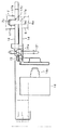
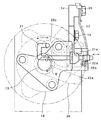
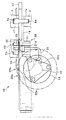
図1は、本発明の一形態に係るパーキング装置が組み込まれた車両用の動力伝達装置の内部構造を示す断面図である。また、図2はこの動力伝達装置を図1の矢印II方向から見た図であり、図3は動力伝達装置を図1の矢印III方向から見た図である。本発明のパーキング装置を説明する前に、まず図1及び図2を参照して動力伝達装置について説明する。図1に示したように動力伝達装置1は、ケース2と、そのケース2内に配置された入力軸3、入出力軸4、及び不図示のデフ軸と一体に回転するデフリングギヤ5とを備えている。ケース2は、図2に示したように第1ケース部材としてのトランスアクスルケース6及び第2ケース部材としてのトランスアクスルハウジング7を入力軸3の回転軸線方向において組み合わせた組立体構造である。入力軸3は、例えば車両に動力源として搭載された内燃機関(以下、エンジンと称することがある。)の出力軸と同軸に連結される。入出力軸4は、エンジン出力の不足分を補うトルクを発生し、あるいはエンジン出力の余剰分で発電を行うモータジェネレータ等の動力発生装置からの入出力軸である。入力軸3と入出力軸4との間では、ギヤ8、9を介してトルクが伝達される。入力軸3の回転は、ギヤ8から不図示のカウンタギヤ等を介してデフリングギヤ5に伝達される。デフリングギヤ5の回転は、不図示のデファレンシャル装置を介して車両の駆動輪に伝達される。このように回転を伝達することにより、動力伝達装置1はエンジンと駆動輪との間の動力伝達経路の一部となる。なお、この形態ではエンジンの他にモータジェネレータ等の動力発生装置を備えた車両に本発明を適用した例を示すため入出力軸4及びギヤ9があるが、本発明はエンジンのみを動力源として備えた車両に適用してもよい。このような車両では、入出力軸4及びギヤ9が省略される。
FIG. 1 is a cross-sectional view showing an internal structure of a power transmission device for a vehicle in which a parking device according to an embodiment of the present invention is incorporated. 2 is a view of the power transmission device as viewed from the direction of arrow II in FIG. 1, and FIG. 3 is a view of the power transmission device as viewed from the direction of arrow III in FIG. Before describing the parking apparatus of the present invention, first, the power transmission apparatus will be described with reference to FIGS. As shown in FIG. 1, the power transmission device 1 includes a case 2, an
次に図1〜図3を参照してパーキング装置10について説明する。このパーキング装置10は、車両のシフトレバーがパーキングの位置に切り替えられた場合に入力軸3の回転をロックし、シフトレバーがパーキング以外の位置に切り替えられた場合にそのロックを解除するものである。パーキング装置10は、パーキングギヤ11と、パーキングポール12と、パーキングポール12を駆動する駆動機構13と、係止部材14とを備えている。パーキングギヤ11は、入力軸3と一体に回転するように入力軸3に設けられている。係止部材14は、複数のボルト15にてトランスアクスルケース6に固定されている。また、係止部材14には、トランスアクスルケース6に対する係止部材14の位置決めを行うためのノックピン16が設けられている。
Next, the
パーキングポール12は、ピボットピン17にて図1の矢印IV方向に回転自在に係止部材14に取り付けられている。そして、パーキングポール12は、駆動機構13に駆動されることにより、パーキングギヤ11と噛み合ってパーキングギヤ11を回転不能に拘束してロックする係合状態と、パーキングギヤ11から離れてパーキングギヤ11の回転を許可してロックを解除する解放状態とに切り替わる。ピボットピン17は、入力軸3と平行に設けられる。そのため、トランスアクスルケース6とトランスアクスルハウジング7とは、パーキングポール12の回転軸線の方向からパーキングギヤ11及びパーキングポール12を挟み込むように組み合わされる。
The
図2に示したようにピボットピン17は、パーキングポール12及び係止部材14を貫通する回転軸部17aと、回転軸部17aより直径が大きいヘッド部17bとを備えている。そのため、回転軸部17aとヘッド部17bとの間には段差17cが設けられる。ピボットピン17の回転軸部17a側の先端は、係止部材14から突出してトランクアクスルケース6に設けられている第1挿入穴6aに嵌め込まれている。また、ピボットピン17のヘッド部17bは、トランスアクスルハウジング7に設けられている第2挿入穴7aに嵌め込まれている。そのため、このピボットピン17によってもトランスアクスルケース6に対する係止部材14の位置決めを行うことができる。回転軸部17aが貫通する係止部材14の貫通孔14aは、その直径φAが第1挿入穴6aの直径φBよりも大きくなるように設けられている(図4参照)。
As shown in FIG. 2, the
図1に示したように駆動機構13は、アクチュエータ18と、回転部材としてのパーキングシャフト19と、パーキングレバー20と、パーキングロッド21と、ディテントスプリング22と、リターンスプリング23とを備えている。アクチュエータ18は、ボルト24にて係止部材14に固定されている。ディテントスプリング22もボルト25にて係止部材14に固定されている。リターンスプリング23は、パーキングポール12が図1の左回りに回転する方向に付勢されるように係止部材14に設けられている。アクチュエータ18は、左右への揺動を制御可能な出力軸18aを備えている。アクチュエータ18は、車両のシフトレバーの位置に基づいて制御される。アクチュエータ18は、シフトレバーがパーキングの位置に切り替えられるとパーキングポール12の位置が係合状態に切り替わり、シフトレバーがパーキング以外の位置に切り替えられるとパーキングポール12の位置が解放状態に切り替わるようにパーキングポール12を駆動する。
As shown in FIG. 1, the
パーキングシャフト19は、一端が出力軸18a内に嵌め込まれ、他端が係止部材14の支持穴14bに回転可能に挿入されている。パーキングシャフト19の一端と出力軸18aとの嵌め合いには、ルーズ嵌合すなわち隙間嵌めが設定される。なお、この部分には、パーキングシャフト19が出力軸18aと一体に動作するように例えばスプライン嵌合が用いられる。一方、パーキングシャフト19の他端と支持穴14bとの嵌め合いには、インロー嵌合が設定される。そのため、パーキングシャフト19は係止部材14に片持支持される。このように一端が出力軸18aに嵌め込まれるとともに他端が支持穴14bに挿入されることにより、パーキングシャフト19はその回転軸線の方向への移動がアクチュエータ18及び係止部材14にて規制される。
One end of the
パーキングシャフト19には、パーキングレバー20が一体に回転するように設けられている。パーキングレバー20は、板状の部材にて形成されている。図3に示したようにパーキングレバー20の外周には、内側に凹む第1凹部20a及び第2凹部20bが設けられている。また、パーキングレバー20は、パーキングロッド21の一端が連結される連結部20cを備えている。パーキングレバー20は、アクチュエータ18の出力軸18aの動作に伴って図3の矢印V方向に揺動する。この際、第1凹部20a又は第2凹部20bにはディテントスプリング22の先端に設けられているローラ22aが嵌る。これによりパーキングレバー20の位置がディテントスプリング22にて保持される。
A
パーキングロッド21は、パーキングレバー20の揺動に伴い図3の左右方向、すなわち図1において紙面に対して垂直な方向に駆動される。パーキングロッド21はカム21aを備えている。このカム21aはパーキングロッド21が図3の右方向、すなわち図1において紙面に対して垂直上方に駆動されるとパーキングポール12と当接してパーキングポール12を図1の右回りに回転させる。一方、パーキングロッド21が図3の左方向、すなわち図1において紙面に対して垂直下方に駆動されるとカム21aによるパーキングポール12の駆動が解除される。そのため、パーキングポール12は、リターンスプリング23によって解放状態に駆動される。
As the
このパーキング装置10によれば、車両のシフトレバーがパーキングの位置に切り替えられるとアクチュエータ18が動作してパーキングロッド21を図3の右方向に駆動する。これによりパーキングポール12が係合状態に切り替わり、入力軸3の回転がロックされる。一方、車両のシフトレバーがパーキング以外の位置に切り替えられるとアクチュエータ18が動作してパーキングロッド21を図3の左方向に駆動する。これによりパーキングポール12が解放状態に切り替わるので、入力軸3のロックが解除される。
According to the
図4は、パーキングポール12の状態を切り替え、これによりパーキングポール12に荷重が掛かったときの係止部材14及びピボットピン17の状態の変化を示している。なお、図4の最も左側の図は、係止部材14をトランスアクスルケース6に固定したときを示している。図4の左から2番目の図は、パーキングポール12に最初に荷重が掛かったときの図を示している。図4の左から3番目の図は、パーキングポール12に2回目の荷重が掛かったときの図を示している。図4の最も右側の図は、パーキングポール12に3回目の荷重が掛かったときの図を示している。すなわち、図4では左側から右側に向かって係止部材14及びピボットピン17の状態の変化が時系列に並べられている。
FIG. 4 shows a change in the state of the locking
上述したように係止部材14はノックピン16及びピボットピン17にてトランスアクスルケース6に対する位置決めが行われるが、図4の最も左側の図に示したように各ピン16、17やそれらのピンが嵌る穴の公差の影響などにより貫通孔14aの中心と第1挿入穴6aの中心とがずれる。そして、このように互いの中心の位置がずれた状態で係止部材14はトランスアクスルケース6に固定される。このような状態において図4の左から2番目の図に示したようにパーキングポール12に図4の右側から荷重が掛かるとピボットピン17が図4の左側に押されて移動する。そして、これにより係止部材14が図4の左側に移動する。この際、この図に示したように係止部材14は貫通孔14aの左側面と第1挿入穴6aの左側面とが揃う位置まで移動する。なお、上述したように係止部材14の貫通孔14aの直径φAは第1挿入穴6aの直径φBより大きいため、貫通孔14aの右側面は第1挿入穴6aの右側面よりも外側(右側)に位置する。
As described above, the locking
次に図4の左から3番目の図に示したようにパーキングポール12に図4の左側から荷重が掛かるとピボットピン17が図4の右側に移動する。上述したように貫通孔14aの右側面は第1挿入穴6aの右側面よりも外側(右側)に位置している。そのため、このようにピボットピン17が右側に移動しても第1挿入穴6a及び第2挿入穴7aでピボットピン17の移動が制限され、係止部材14にピボットピン17に掛かっている荷重が作用することを防止できる。その後、図4の最も右側の図に示したようにピボットピン14に右側から荷重が掛かってもピボットピン17は左側に移動するが、既に貫通孔14aの左側面と第1挿入穴6aの左側面とが揃っているため、ピボットピン17に掛かっている荷重が係止部材14に作用することを防止できる。
Next, as shown in the third drawing from the left in FIG. 4, when a load is applied to the
このようにパーキング装置10では、係止部材14はピボットピン17に最初に荷重が掛かったときにだけ移動し、それ以降はピボットピン17に荷重が掛かっても移動しない。そのため、係止部材14を固定しているボルト15が緩むことを抑制できる。
As described above, in the
次にパーキング装置10を動力伝達装置1に取り付ける手順について説明する。パーキングギヤ11は、周知の方法で入力軸3に取り付けられる。一方、それ以外のパーキングポール12及び駆動機構13については、これらの部品をまず係止部材14に組み付けてサブアセンブリ化する。次に、これら部品が組み付けられた係止部材14をボルト15でトランスアクスルケース6に固定する。その後、トランスアクスルケース6にトランスアクスルハウジング7が組み合わされることにより、ケース2内にパーキング装置10が収容される。
Next, a procedure for attaching the
本発明のパーキング装置10によれば、ピボットピン17の回転軸部17aの先端が第1挿入穴6aに嵌め込まれ、ヘッド部17bが第2挿入穴7aに嵌め込まれているので、パーキングポール12に掛かった荷重をケース2で受けることができる。そのため、係止部材14の大型化を防止したり、ボルト15の本数を減少させることができる。また、ピボットピン17によっても係止部材14の位置決めを行うことができるので、部品数を削減できる。そのため、パーキング装置10を小型化することができる。ピボットピン17は、係止部材14を貫通してケース2に嵌め込まれるので、ケース2に対するパーキングポール12の取付位置の精度を向上させることができる。これにより、パーキングギヤ11とパーキングポール12とを適正に噛み合わせることができるので、パーキングギヤ11からパーキングポール12が抜けることを防止できる。
According to the
係止部材14の貫通孔14aの直径φAを第1挿入穴6aの直径φBより大きくしたので、ボルト15の緩みを抑制できる。そのため、ケース2に対する係止部材14のがたつきを抑えることができる。
Since the diameter φA of the through
パーキングシャフト19を係止部材14に片持支持させたので、パーキングポール12に掛かった荷重がパーキングシャフト19に作用してもその荷重の一部を係止部材14で受けることができる。これにより、アクチュエータ18に入力される荷重を軽減できるので、アクチュエータ18が破損することを抑制できる。また、パーキングシャフト19の回転軸線方向への移動をアクチュエータ18及び係止部材14で規制するので、部品数を削減することができる。そのため、コストを低減したり装置を小型化したりすることができる。
Since the
本発明のパーキング装置10では、パーキングポール12及び駆動機構13を係止部材14に組み付けてサブアセンブリ化した後、これらの部品をまとめてケース2に取り付けるので、パーキング装置10の組み付け作業の手間を軽減することができる。また、ピボットピン17の回転軸部17aとヘッド部17bとの間に段差17cを設けたので、係止部材14をケース2に組み付ける際などにピボットピン17がパーキングポール12及び係止部材14から抜け落ちることを抑制できる。
In the
図5は、本発明の他の形態に係るパーキング装置10が組み込まれた車両用の動力伝達装置1を示している。図5は上述した形態の図2に対応する図である。図5において上述した形態と共通の部分には同一の符号を付して説明を省略する。この形態では、係止部材14がパーキングロッド21を案内するガイド部30を備えている。ガイド部30は、第1ガイド部31及び第2ガイド部32を備えている。第1ガイド部31は、係止部材14からトランスアクスルケース6側に突出するように設けられている。第2ガイド部32は、係止部材14からトランスアクスルハウジング7側に突出するように設けられている。トランスアクスルハウジング7には、第2ガイド部32が挿入される挿入穴7bが設けられている。挿入穴7bの深さは、第2ガイド部32の高さより若干大きく設定されている。挿入穴7b内には、第2ガイド部32を図5の下方に付勢するバネ手段としての皿バネ40が設けられている。
FIG. 5 shows a power transmission device 1 for a vehicle in which a
この形態のパーキング装置10においては、パーキング装置10をケース2に組み付けたときにケース2とパーキング装置10との間に寸法誤差などに起因する隙間などが生じても皿バネ40によって係止部材14をトランスアクスルケース6側に押し付けることができるので、係止部材14をケース2に密着させることができる。そのため、車両の走行時などに係止部材14がケース2に対してがたつくことを防止できる。そのため、係止部材の摩耗や破損を抑制できる。なお、係止部材14をケース2に押し付けるバネ手段は皿バネ40に限定されず、コイルバネなど種々のバネを使用してよい。皿バネ40を設ける位置は図5に示した位置に限定されず、係止部材14をケース2に押し付けることが可能な種々の位置に設けてよい。また、皿バネ40の個数も1個に限定されず、複数個の皿バネ40を設けてもよい。
In the
本発明は、上述した形態に限定されることなく、種々の形態にて実施することができる。例えば、ピボットピンは全長に亘って同じ直径で形成されていてもよい。本発明のパーキング装置は、アクチュエータでパーキングポールを駆動するものに限定されない。例えば、パーキングシャフトが車両のシフトレバーのシフト操作と連動して動作するようにパーキングシャフトとシフトレバーとが機械的に接続されたパーキング装置に本発明を適用してもよい。本発明のパーキング装置が適用される車両は、モータジェネレータなどの動力発生装置及び内燃機関の両方を動力源として備えたハイブリッド車両に限定されない、本発明は、内燃機関のみ又は電動機のみが動力源として設けられた車両に適用してもよい。 The present invention is not limited to the above-described form and can be implemented in various forms. For example, the pivot pin may be formed with the same diameter over the entire length. The parking apparatus of the present invention is not limited to the one that drives the parking pole with the actuator. For example, the present invention may be applied to a parking apparatus in which a parking shaft and a shift lever are mechanically connected so that the parking shaft operates in conjunction with a shift operation of a vehicle shift lever. The vehicle to which the parking device of the present invention is applied is not limited to a hybrid vehicle including both a power generation device such as a motor generator and an internal combustion engine as a power source. The present invention can be applied only to an internal combustion engine or an electric motor as a power source. You may apply to the provided vehicle.
2 ケース
6 トランスアクスルケース
6a 第1挿入穴
7 トランスアクスルハウジング
7a 第2挿入穴
10 パーキング装置
11 パーキングギヤ
12 パーキングポール
14 係止部材
14a 貫通孔
14b 支持穴
15 ボルト
17 ピボットピン
17a 回転軸部
17b ヘッド部
18 アクチュエータ
18a 出力軸
19 パーキングシャフト(回転部材)
21 パーキングロッド
40 皿バネ(バネ手段)
φA 貫通孔の直径
φB 第1挿入穴の直径
2
21
φA Diameter of the through hole φB Diameter of the first insertion hole
Claims (5)
前記ケースは、前記パーキングポールの回転軸線の方向から前記パーキングギヤ及び前記パーキングポールを挟み込むように組み合わされる第1ケース部材及び第2ケース部材を備え、
前記パーキングポールがピボットピンにて回転自在に取り付けられるとともに前記第1ケース部材に固定される係止部材を備え、
前記ピボットピンは、前記パーキングポール及び前記係止部材を貫通して前記パーキングポールを前記係止部材に回転自在に取り付け、かつ一端が前記係止部材から突出して前記第1ケース部材に設けられた第1挿入穴に嵌め込まれているとともに他端が前記パーキングポールから突出して前記第2ケース部材に設けられた第2挿入穴に嵌め込まれていることを特徴とする車両用パーキング装置。 A parking gear provided in a power transmission path from the power source of the vehicle to the drive wheel, and a rotation gear provided in a case in which the parking gear is accommodated, meshing with the parking gear, In a vehicle parking apparatus comprising: a parking pole that is switchable between an engagement state that restricts the rotation of the parking gear and a release state that permits rotation of the parking gear away from the parking gear;
The case includes a first case member and a second case member that are combined so as to sandwich the parking gear and the parking pole from the direction of the rotation axis of the parking pole,
The parking pole is rotatably attached by a pivot pin and includes a locking member fixed to the first case member,
The pivot pin is provided on the first case member so as to penetrate the parking pole and the locking member and rotatably attach the parking pole to the locking member, and one end protrudes from the locking member. A vehicle parking apparatus, wherein the vehicle parking apparatus is fitted into a first insertion hole and has the other end protruding from the parking pole and fitted into a second insertion hole provided in the second case member.
前記係止部材に設けられている前記ピボットピンが貫通する貫通孔の直径は、前記第1挿入穴の直径より大きい請求項1〜3のいずれか一項に記載の車両用パーキング装置。 The locking member is fixed to the first case member with a bolt,
The vehicle parking apparatus according to any one of claims 1 to 3, wherein a diameter of a through hole through which the pivot pin provided in the locking member passes is larger than a diameter of the first insertion hole.
前記回転部材は、回転軸線方向への移動が前記アクチュエータ及び前記係止部材にて規制されるように一端が前記出力軸に嵌め込まれるとともに他端が前記係止部材に設けられた支持穴に挿入されている請求項1〜4のいずれか一項に記載の車両用パーキング装置。 An actuator having an output shaft; a rotating member attached to the output shaft; and a parking rod that operates integrally with the rotating member to drive the parking pole;
One end of the rotating member is fitted into the output shaft and the other end is inserted into a support hole provided in the locking member so that movement in the rotation axis direction is regulated by the actuator and the locking member. The vehicle parking apparatus as described in any one of Claims 1-4.
Priority Applications (1)
| Application Number | Priority Date | Filing Date | Title |
|---|---|---|---|
| JP2008219898A JP4821820B2 (en) | 2008-08-28 | 2008-08-28 | Vehicle parking device |
Applications Claiming Priority (1)
| Application Number | Priority Date | Filing Date | Title |
|---|---|---|---|
| JP2008219898A JP4821820B2 (en) | 2008-08-28 | 2008-08-28 | Vehicle parking device |
Publications (2)
| Publication Number | Publication Date |
|---|---|
| JP2010052594A true JP2010052594A (en) | 2010-03-11 |
| JP4821820B2 JP4821820B2 (en) | 2011-11-24 |
Family
ID=42068969
Family Applications (1)
| Application Number | Title | Priority Date | Filing Date |
|---|---|---|---|
| JP2008219898A Expired - Fee Related JP4821820B2 (en) | 2008-08-28 | 2008-08-28 | Vehicle parking device |
Country Status (1)
| Country | Link |
|---|---|
| JP (1) | JP4821820B2 (en) |
Citations (11)
| Publication number | Priority date | Publication date | Assignee | Title |
|---|---|---|---|---|
| JPS6065125U (en) * | 1983-10-13 | 1985-05-09 | 日産自動車株式会社 | Automatic transmission side cover mounting structure |
| JPS60116545A (en) * | 1983-11-29 | 1985-06-24 | Fuji Heavy Ind Ltd | Parking locking device of car |
| JPS6281123U (en) * | 1985-11-06 | 1987-05-23 | ||
| JPH06219249A (en) * | 1993-01-28 | 1994-08-09 | Aichi Mach Ind Co Ltd | Parking mechanism for transmission |
| JPH0678132U (en) * | 1993-04-23 | 1994-11-01 | ジャトコ株式会社 | Automatic transmission parking mechanism |
| JPH07205773A (en) * | 1994-01-12 | 1995-08-08 | Jatco Corp | Parking mechanism for automatic transmission |
| JPH08207717A (en) * | 1995-02-08 | 1996-08-13 | Daihatsu Motor Co Ltd | Return spring locking structure for parking lock pole |
| JPH08216842A (en) * | 1995-02-15 | 1996-08-27 | Fuji Heavy Ind Ltd | Parking mechanism of automatic transmission |
| JP2004116738A (en) * | 2002-09-27 | 2004-04-15 | Toyota Motor Corp | Drive unit with parking mechanism |
| JP2007205578A (en) * | 2007-05-14 | 2007-08-16 | Toyota Motor Corp | Driving device with parking mechanism |
| JP2008174190A (en) * | 2007-01-22 | 2008-07-31 | Mitsuba Corp | Electric actuator for parking lock device |
-
2008
- 2008-08-28 JP JP2008219898A patent/JP4821820B2/en not_active Expired - Fee Related
Patent Citations (11)
| Publication number | Priority date | Publication date | Assignee | Title |
|---|---|---|---|---|
| JPS6065125U (en) * | 1983-10-13 | 1985-05-09 | 日産自動車株式会社 | Automatic transmission side cover mounting structure |
| JPS60116545A (en) * | 1983-11-29 | 1985-06-24 | Fuji Heavy Ind Ltd | Parking locking device of car |
| JPS6281123U (en) * | 1985-11-06 | 1987-05-23 | ||
| JPH06219249A (en) * | 1993-01-28 | 1994-08-09 | Aichi Mach Ind Co Ltd | Parking mechanism for transmission |
| JPH0678132U (en) * | 1993-04-23 | 1994-11-01 | ジャトコ株式会社 | Automatic transmission parking mechanism |
| JPH07205773A (en) * | 1994-01-12 | 1995-08-08 | Jatco Corp | Parking mechanism for automatic transmission |
| JPH08207717A (en) * | 1995-02-08 | 1996-08-13 | Daihatsu Motor Co Ltd | Return spring locking structure for parking lock pole |
| JPH08216842A (en) * | 1995-02-15 | 1996-08-27 | Fuji Heavy Ind Ltd | Parking mechanism of automatic transmission |
| JP2004116738A (en) * | 2002-09-27 | 2004-04-15 | Toyota Motor Corp | Drive unit with parking mechanism |
| JP2008174190A (en) * | 2007-01-22 | 2008-07-31 | Mitsuba Corp | Electric actuator for parking lock device |
| JP2007205578A (en) * | 2007-05-14 | 2007-08-16 | Toyota Motor Corp | Driving device with parking mechanism |
Also Published As
| Publication number | Publication date |
|---|---|
| JP4821820B2 (en) | 2011-11-24 |
Similar Documents
| Publication | Publication Date | Title |
|---|---|---|
| JP2011511218A (en) | Emergency unlocking device for park lock | |
| US7284648B2 (en) | Non-sealed park actuator guide for hybrid transmission and method | |
| JP5168405B2 (en) | Device for preventing rattling of vehicle | |
| JP2009143348A (en) | Drive device for hybrid vehicle | |
| KR102363663B1 (en) | Brake force transmission unit, brake subassembly and brake assembly group | |
| KR20100053278A (en) | Parking device for electrical vehicle | |
| WO2011161719A1 (en) | Parking lock device | |
| CN111720540B (en) | Parking device for vehicle | |
| CN109268483A (en) | Actuator assembly for transmission shifter | |
| US11773973B2 (en) | Parking mechanism and drive apparatus | |
| WO2019176771A1 (en) | Parking lock device of vehicle drive device, and vehicle drive device | |
| JP6173503B1 (en) | Range switching device | |
| EP2330310A1 (en) | Actuator for operating a differential lock | |
| JP2022091762A (en) | Motor unit | |
| JP2012072854A (en) | Electric actuator for parking lock | |
| JP4821820B2 (en) | Vehicle parking device | |
| EP1338493B1 (en) | Mechanism with variable transmission ratio | |
| JP2010274702A (en) | Parking device structure | |
| US7758463B2 (en) | Power transmitting apparatus | |
| JP6565457B2 (en) | Manual release mechanism for vehicle parking lock device | |
| JP4973604B2 (en) | Parking device structure | |
| JP2019023050A (en) | Steering device for vehicle | |
| CN211599511U (en) | Parking device for vehicle | |
| CN115427712A (en) | Releasing device | |
| JP6716174B2 (en) | Power transmission unit |
Legal Events
| Date | Code | Title | Description |
|---|---|---|---|
| A621 | Written request for application examination |
Free format text: JAPANESE INTERMEDIATE CODE: A621 Effective date: 20101124 |
|
| A977 | Report on retrieval |
Free format text: JAPANESE INTERMEDIATE CODE: A971007 Effective date: 20110311 |
|
| A131 | Notification of reasons for refusal |
Free format text: JAPANESE INTERMEDIATE CODE: A131 Effective date: 20110322 |
|
| A521 | Request for written amendment filed |
Free format text: JAPANESE INTERMEDIATE CODE: A523 Effective date: 20110519 |
|
| TRDD | Decision of grant or rejection written | ||
| A01 | Written decision to grant a patent or to grant a registration (utility model) |
Free format text: JAPANESE INTERMEDIATE CODE: A01 Effective date: 20110809 |
|
| A01 | Written decision to grant a patent or to grant a registration (utility model) |
Free format text: JAPANESE INTERMEDIATE CODE: A01 |
|
| A61 | First payment of annual fees (during grant procedure) |
Free format text: JAPANESE INTERMEDIATE CODE: A61 Effective date: 20110822 |
|
| R151 | Written notification of patent or utility model registration |
Ref document number: 4821820 Country of ref document: JP Free format text: JAPANESE INTERMEDIATE CODE: R151 |
|
| FPAY | Renewal fee payment (event date is renewal date of database) |
Free format text: PAYMENT UNTIL: 20140916 Year of fee payment: 3 |
|
| LAPS | Cancellation because of no payment of annual fees |