JP2010051885A - Pig cleaner and pig cleaning method of piping - Google Patents
Pig cleaner and pig cleaning method of piping Download PDFInfo
- Publication number
- JP2010051885A JP2010051885A JP2008218643A JP2008218643A JP2010051885A JP 2010051885 A JP2010051885 A JP 2010051885A JP 2008218643 A JP2008218643 A JP 2008218643A JP 2008218643 A JP2008218643 A JP 2008218643A JP 2010051885 A JP2010051885 A JP 2010051885A
- Authority
- JP
- Japan
- Prior art keywords
- pig
- pipe
- cleaning tool
- cleaning
- pigs
- Prior art date
- Legal status (The legal status is an assumption and is not a legal conclusion. Google has not performed a legal analysis and makes no representation as to the accuracy of the status listed.)
- Granted
Links
Images


Abstract
Description
本発明は、ピグ洗浄具及び配管のピグ洗浄方法に関する。 The present invention relates to a pig cleaning tool and a pipe cleaning method for piping.
例えば、水道用の配管は管径50mm以上の主配管と、各住戸に給水するために主配管
に接続された管径15〜25mmの引き込み管とによって網状に構成されているのが一般的である。このような網状の配管では主配管及び引き込み管の内部汚れを定期的に、又は任意の時期に洗浄するのが普通である。中でも比較的小規模の水道である簡易水道又は専用水道の場合は、井戸水を利用することが多いため、次に説明するように管が汚れやすく洗浄頻度が多くなる傾向にある。
For example, water supply pipes are generally configured in a net shape by main pipes having a pipe diameter of 50 mm or more and lead-in pipes having a pipe diameter of 15 to 25 mm connected to the main pipes for supplying water to each dwelling unit. is there. In such a net-like pipe, it is usual to clean internal stains of the main pipe and the lead-in pipe regularly or at an arbitrary time. In particular, in the case of a simple water supply or a dedicated water supply which is a relatively small-scale water supply, well water is often used, so that the pipe tends to become dirty and the frequency of cleaning tends to increase as described below.
すなわち、井戸水は土壌由来の鉄、マンガン等を含むことが多く、マンガンは消毒剤の
塩素によって酸化され汚れ物質(黒い粒子)となって析出する。この汚れ物質は、水道水中に混入し管に付着し、時間の経過によって脱落して水道水中に混入する。そこで、管に付着した汚れ物質は、定期的又は任意の時期に洗浄して除去する必要がある。
That is, well water often contains iron, manganese, and the like derived from soil, and manganese is oxidized by a disinfectant chlorine and deposited as a dirt substance (black particles). This contaminated material is mixed in tap water and adheres to the pipe, drops off over time, and mixes in tap water. Therefore, it is necessary to clean and remove the dirt substance adhering to the tube periodically or at an arbitrary time.
従来、水道水等の配管を洗浄する技術として、高圧水の管内噴射によって汚れを落とす
洗浄方法、洗浄剤を管内に充填して空気でバブリングすることにより管壁の汚れを落とす洗浄方法が知られていた。
Conventionally, as a technique for cleaning pipes such as tap water, a cleaning method for removing dirt by in-pipe injection of high-pressure water, and a cleaning method for removing dirt from a pipe wall by filling the pipe with a cleaning agent and bubbling with air are known. It was.
しかし、従来の高圧水による管の洗浄方法では、高圧水用の洗浄チューブを管内に挿入
し管内全面にむらなく高圧水を噴射する必要があるので、非常に時間がかかるという問題があった。また、洗浄液を管内に充填して空気でバブリングする洗浄方法では、エアーバブリングによる剥離効果が弱く洗浄に時間がかかるという問題、管全体に洗浄液を充満させる必要があるため、多量の洗浄液が必要となり、コストアップになるという問題があった。
However, the conventional method of cleaning a tube with high-pressure water has a problem that it takes a very long time because a high-pressure water cleaning tube needs to be inserted into the tube and the high-pressure water must be uniformly sprayed over the entire surface of the tube. In addition, the cleaning method in which the cleaning liquid is filled in the tube and bubbled with air has a problem that the peeling effect by air bubbling is weak and it takes time to clean, and it is necessary to fill the entire tube with the cleaning solution. There was a problem of cost increase.
そこで、管を比較的短時間に且つ低コストで洗浄できるピグ洗浄方法が提案されている
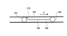
(例えば、特許文献1参照。)。特許文献1のピグ洗浄方法は、図9に示すように、洗浄液104をサンドイッチした前後2つのピグ100、101がひも102で連結されたピグ洗浄具110を管103内に挿入し、このピグ洗浄具110を空気圧又は窒素圧で移動させることにより、管103の内面に付着した汚れを除去するものである。なお、ピグを水圧で移動させる方法もある。
Therefore, a pig cleaning method that can clean the tube in a relatively short time and at a low cost has been proposed (for example, see Patent Document 1). In the pig cleaning method of Patent Document 1, as shown in FIG. 9, a
特許文献1のピグ洗浄方法では、管103内に挿入したピグ洗浄具を空気圧又は窒素圧
で移動させるので、管103が長い場合でもピグ洗浄具を先端まで移動させることにより、管103の先端まで洗浄できる。また、ピグ100、101は管103の内面に接触するので汚れ物質等の剥離効果が高く、洗浄液104を管103内に充満させてバブリングする洗浄方法に比べて、管103を短時間で洗浄できる。更に、洗浄液104は前後のピグ100、101の間に充填すればよいので、洗浄液の量を少なくしてコストダウンを図ることができる。
しかしながら、従来のピグは管との密着性を確保するために、弾力性のある合成樹脂や
ゴムの発泡体で形成され、発泡密度が20mg/cm3以上の比較的硬質の材料で成形さ
れるのが普通であり、その外径は管の内径の1〜1.05倍程度に形成されていたため、配管にエルボ継ぎ手などの段差部分がある場合、ピグが段差部分の隅の方に充分に密着するまで変形せず、管の洗浄が不十分になるという問題があった。
However, the conventional pig is formed of a flexible synthetic resin or rubber foam to ensure adhesion to the tube, and is formed of a relatively hard material having a foam density of 20 mg / cm 3 or more. Since the outer diameter of the pipe is about 1 to 1.05 times the inner diameter of the pipe, if there is a stepped part such as an elbow joint in the pipe, the pig should be sufficiently close to the corner of the stepped part. There was a problem in that the tube was not deformed until it adhered and the tube was not sufficiently cleaned.
また、水道配管のように、主配管に多数の引き込み管が接続されている場合、洗浄対象
となる管と洗浄対象外の管とを止水弁や仕切弁によって縁切りし、洗浄中の管以外の管に洗浄中の管内の洗浄液や汚れ物質などが流れ込まないようにするのが普通である。しかし、従来のピグは、管壁への密着力が大きいため、ピグを管内で移動させるためには、約0.3MPa以上の空気圧や水圧等で加圧する必要があった。このため、止水弁や仕切弁の閉鎖が不十分で隙間がある場合には、洗浄中の管内の洗浄液や汚れ物質等が圧力空気或いは圧力水によって押圧されて弁の隙間から洗浄対象外の管に流れ込むおそれがあった。
In addition, when a large number of lead-in pipes are connected to the main pipe, such as water pipes, the pipes that are to be cleaned and the pipes that are not to be cleaned are separated by a water stop valve or gate valve, It is usual to prevent the cleaning liquid and dirt in the pipe being cleaned from flowing into the pipe. However, since the conventional pig has a high adhesion force to the tube wall, in order to move the pig within the tube, it has been necessary to pressurize it with an air pressure or a water pressure of about 0.3 MPa or more. For this reason, when the stoppage of the water stop valve or gate valve is insufficient and there is a gap, the cleaning liquid or dirt substance in the pipe being cleaned is pressed by the pressure air or the pressure water and is not cleaned from the clearance of the valve. There was a risk of flowing into the tube.
本発明は、かかる従来の問題点を解決するためになされたもので、管に段差部分がある場合でも確実に洗浄でき、また、洗浄中の管内の洗浄液等が洗浄対象外の管に流れ込むのを抑制できるピグ洗浄具、及び配管の洗浄方法を提供することを目的とする。 The present invention has been made to solve such a conventional problem, and even when there is a step portion in the pipe, the pipe can be reliably washed, and the washing liquid in the pipe being washed flows into the pipe not to be washed. An object of the present invention is to provide a pig cleaning tool and a pipe cleaning method capable of suppressing the above.
本発明は、前記課題を解決するため、以下の手段を採用した。
すなわち、本発明は、軟質性の材料で形成されると共に、洗浄の対象となる管の内径より大きな直径を有し、且つ一列に配置された複数の球形ピグと、前記複数のピグに一体的に被せられたネットと、を備える。
The present invention employs the following means in order to solve the above problems.
That is, the present invention includes a plurality of spherical pigs formed of a soft material and having a diameter larger than the inner diameter of a tube to be cleaned and arranged in a row, and integrally formed with the plurality of pigs. And a net overlaid on.
本発明によれば、ピグが軟質性の材料で形成されているので、洗浄対象の管に継ぎ手等の段差部分がある場合でも、ピグが段差部分の隅に接触して確実に洗浄できる。また、ピグが軟質性を有するため、ピグが管の内面に接触した際にネットがピグの外周面から内側に埋め込まれて、ピグの外周面が管の内面全体に接触して洗浄できる。 According to the present invention, since the pig is formed of a soft material, even if the pipe to be cleaned has a stepped portion such as a joint, the pig can be reliably cleaned by contacting the corner of the stepped portion. Further, since the pig has softness, when the pig contacts the inner surface of the pipe, the net is embedded inside from the outer peripheral surface of the pig, and the outer peripheral surface of the pig can contact the entire inner surface of the pipe for cleaning.
ここで、前記ピグは、発泡密度が0.08〜0.12mg/cm3、好ましくは0.1
mg/cm3の発泡材で形成できる。また、前記ピグの外径は、前記管の内径の1.05
〜1.1倍、好ましくは1.08倍にするのが好ましい。発泡材は、連続気泡と独立気泡とが混在し、気体が透過しない状態にするのが好ましい。上記発泡密度と、外径とすることにより、ピグを真空吸引することが可能になる。本発明のピグは、従来のピグに比べて管壁への密着力は低いのでピグ単独での洗浄力が多少低くなるものの、洗浄液と組み合わせることで充分な洗浄が可能になる。
Here, the pig has a foaming density of 0.08 to 0.12 mg / cm 3 , preferably 0.1
It can be formed with a foam material of mg / cm 3 . The outer diameter of the pig is 1.05 of the inner diameter of the tube.
It is preferable to make it -1.1 times, preferably 1.08 times. It is preferable that the foam material is in a state in which open cells and closed cells are mixed and gas is not transmitted. By setting the foaming density and the outer diameter, the pig can be sucked in vacuum. Since the pig of the present invention has a lower adhesion to the tube wall than conventional pigs, the cleaning power of the pig alone is somewhat lower, but sufficient cleaning is possible by combining it with a cleaning solution.
また、本発明のピグ洗浄具は、複数のピグとネットとを組み合わせることによって、前
後のピグを連結することで、ピグ間の洗浄液と一体になって移動することが可能になる。また、複数のピグにネットを被せることで真空吸引移動時にピグの変形を抑えて洗浄液の漏れを防止できる。従来の特許文献1のピグ洗浄具は、ひもでピグの中心を結んで引っ張ると軟質ピグの場合はピグが扁平になってしまうが、本発明のように、ネットをピグ全体に被せることにより、ピグが扁平になるのを抑制できるので、洗浄液の漏れを防ぐと共にピグの管壁への密着力の低下を防ぐことができる。
Further, the pig cleaning tool of the present invention can move together with the cleaning liquid between the pigs by combining the plurality of pigs and the net to connect the front and rear pigs. Further, by covering the plurality of pigs with the net, it is possible to prevent the leakage of the cleaning liquid by suppressing the deformation of the pigs during the vacuum suction movement. When the conventional pig cleaning tool of Patent Document 1 is pulled by connecting the center of the pig with a string, the pig becomes flat in the case of a soft pig, but by covering the entire pig as in the present invention, Since it is possible to prevent the pig from becoming flat, it is possible to prevent the cleaning liquid from leaking and to prevent a reduction in the adhesion of the pig to the tube wall.
また、本発明は、配管を構成する管のうち洗浄の対象となる管の両端部を開放するステ
ップと、上記いずれかのピグ洗浄具を前記管の他端部側から挿入するステップと、前記管内の前記ピグ洗浄具を前記管の前記一端部側から真空吸引して前記一端部側に移動させるステップと、を備える、
The present invention also includes a step of opening both ends of a pipe to be cleaned among the pipes constituting the pipe, a step of inserting any one of the above-described pig cleaning tools from the other end side of the pipe, Vacuuming the pig cleaning tool in the tube from the one end side of the tube and moving it to the one end side; and
本発明によれば、軟質性の材料で形成され、管の内径より大きな直径を有する複数のピ
グにネットを被せたピグ洗浄具を管に挿入し、このピグ洗浄具を真空吸引によって移動させるので、管内の洗浄液や汚れ物質に圧力が作用しない。従って、洗浄対象の管と洗浄対象外の管との間に設けられた弁に隙間がある場合でも、洗浄中の管内における洗浄液や汚れ物質等が洗浄対象外の管に流れ込むのを抑制できる。
According to the present invention, a pig cleaning tool formed of a soft material and having a net covered with a plurality of pigs having a diameter larger than the inner diameter of the pipe is inserted into the pipe, and the pig cleaning tool is moved by vacuum suction. The pressure does not act on the cleaning liquid and dirt in the pipe. Therefore, even when there is a gap in the valve provided between the pipe to be cleaned and the pipe not to be cleaned, it is possible to prevent the cleaning liquid, the dirt substance, and the like in the pipe being cleaned from flowing into the pipe not to be cleaned.
ここで、前記ピグ洗浄具を移動させるステップでは、前記ピグ洗浄具を前記管の前記他
端部側から引っ張ることにより、前記ピグ洗浄具の移動速度を調整することができる。この場合は、管の内径、ピグの直径、洗浄液や配管から剥離した汚れ物質の特性などに応じて、ピグ洗浄具の移動速度を調整することができるので、洗浄効果を高くできる。
Here, in the step of moving the pig cleaning tool, the moving speed of the pig cleaning tool can be adjusted by pulling the pig cleaning tool from the other end side of the tube. In this case, since the moving speed of the pig cleaning tool can be adjusted according to the inner diameter of the pipe, the diameter of the pig, the characteristics of the cleaning liquid or the dirt substance peeled off the pipe, the cleaning effect can be enhanced.
また、前記ピグ洗浄具を巻き取り装置から繰り出されるロープによって引っ張り、前記
巻き取り装置における前記ロープの繰り出し速度を調整することにより、前記ピグ洗浄具の移動速度を調整することができる。この場合は、ピグ洗浄具の移動速度を自動的に調整できる。
Moreover, the moving speed of the pig cleaning tool can be adjusted by pulling the pig cleaning tool with a rope fed from the winding device and adjusting the feeding speed of the rope in the winding device. In this case, the moving speed of the pig cleaning tool can be automatically adjusted.
さらに、前記ピグ洗浄具を、前記管の前記他端部側から圧縮空気で押圧することができ
る。この場合は、ピグ洗浄具を前方から真空吸引し、且つ後方から圧縮空気で押圧するので、小径の管のようにピグ洗浄具の移動に対する抵抗力が大きい場合でもピグ洗浄具を確実に移動させることができる。
Furthermore, the said pig cleaning tool can be pressed with compressed air from the said other end part side of the said pipe | tube. In this case, the pig washer is vacuum-sucked from the front and pressed with compressed air from the rear, so that the pig washer can be reliably moved even when the resistance to movement of the pig washer is large, such as a small-diameter tube. be able to.
また、前記複数の球形ピグ間に洗浄液を充填することができる。この場合は、洗浄効率
を更に高くできる。
In addition, a cleaning liquid can be filled between the plurality of spherical pigs. In this case, the cleaning efficiency can be further increased.
本発明によれば、管に段差部分がある場合でも確実に洗浄できる。また、洗浄対象となる管と洗浄帯対象外の管との接続部に設けられた弁に隙間がある場合でも、洗浄中の管内の洗浄液等が洗浄対象外の管に流れ込むのを抑制できる。 According to the present invention, even when the pipe has a stepped portion, it can be reliably washed. Further, even when there is a gap in the valve provided at the connection portion between the pipe to be cleaned and the pipe not to be cleaned, it is possible to suppress the cleaning liquid in the pipe being cleaned from flowing into the pipe not to be cleaned.
次に、本発明に係る配管のピグ洗浄方法について図面を参照して詳細に説明する。なお、本実施形態は一実施例であり、本発明は実施形態に限定されない。 Next, the pig cleaning method for piping according to the present invention will be described in detail with reference to the drawings. This embodiment is an example, and the present invention is not limited to the embodiment.
<配管の構成>
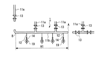
図1は、本発明に係る配管のピグ洗浄方法を適用する配管1を示す。この配管1は、本
管10、本管10から枝分かれした枝管11、本管10又は枝管11に設けられた引き込み管12、本管10又は枝管11に設けられた仕切弁13、引き込み管12に設けられた止水弁14、及び引き込み管12の流水量を計測する量水器19を備えている。本実施形態では、本管10及び枝管11の呼び径が100A、引き込み管12の呼び径が20Aである。また、本管10、枝管11及び引き込み管12は、硬質塩化ビニル製である。
<Piping configuration>
FIG. 1 shows a pipe 1 to which a pipe pig cleaning method according to the present invention is applied. The pipe 1 includes a
枝管11は、本管10に接続され互いに間隔を開けて配置された複数の第1枝管11a
と、第1枝管11aの先端部を接続する第2枝管11bとを有している。引き込み管12は、本管10又は第1,第2枝管11a,11bに、それぞれ複数設けられている。これらの引き込み管12は、例えば住宅等に引き込まれている。なお、本実施形態では、配管1の第2枝管11b及び引き込み管12を洗浄する場合について説明する。
The
And a
<ピグ洗浄具の構成>
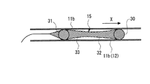
図2は、本発明の実施形態に係るピグ洗浄具15を示す。このピグ洗浄具15は、2つ
の弾力性及び軟質性を有する球形のピグ30,31が適宜な間隔を開けて一列に並べられ、これらのピグ30,31に樹脂製のネット32が被せられている。このピグ洗浄具15
を用いて配管を洗浄する場合は、ピグ30,31の間に洗浄液33を充填する。なお、ピグは3個以上使用することができる。また、以下の説明では、管の洗浄時にピグ洗浄具15が移動する方向Xに対して前方にあるピグ30をガイドピグと呼び、後方にあるピグ31をカバーピグと呼ぶ。
<Pig cleaning tool configuration>
FIG. 2 shows a
When the piping is cleaned using the cleaning
本実施形態では、各ピグ30,31がポリウレタンによって形成され、その発泡密度が
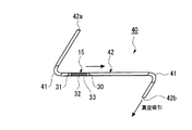
0.08〜0.12mg/cm3、望ましくは0.1mg/cm3に設定されている。ここで、各ピグ30,31の発泡密度と配管の通過状況との関係を実験により求めた。図3は、実験装置40を示す。この実験装置40は、2個のエルボ継ぎ手41を有する管42と、この管42内に挿入されたピグ洗浄具15と、を有する。
In this embodiment, each
管42の材質は耐衝撃性硬質塩化ビニル管(HIVP)、呼び径50A、管長は25m
、管42の2カ所に90度エルボ継ぎ手41が設けられている。また、ガイドピグ30及びカバーピグ31の形状は球形、発泡条件は連続気泡体+独立気泡体、直径は55mm、ガイドピグ30とカバーピグ31との間隔は2mである。なお、独立気泡体とは、周知のように内部に気泡が存在するが気泡同士が壁で仕切られていて繋がっていないものをいう。連続気泡体とは、気泡同士が繋がっているものをいう。
The material of the
, 90 degree elbow joints 41 are provided at two locations on the
実験は、管42の一端部42aからピグ洗浄具15を挿入し、配管42の他端部42b
から真空吸引してピグ洗浄具15を他端部42b側に移動させたときの真空度、及び移動時間を計測すると共に、ピグ洗浄具15の移動状況及び洗浄液33の漏れ状況を観察した。
In the experiment, the
Then, the degree of vacuum and the movement time when the
図4は、実験結果を示す。この実験結果から分かるように、各ピグ30,31の発泡密
度が低すぎる場合(実験NO.1)は、ピグ30,31間に充填された洗浄液33がガイドピグ30から前方に漏れてしまうおそれがある。また、発泡密度が高すぎる場合(実験NO.3,4)は、ピグ洗浄具15がエルボ継ぎ手41を滑らかに通過しないおそれがある。
FIG. 4 shows the experimental results. As can be seen from the experimental results, when the foam density of the
また、発泡密度が適切に設定されている場合(実験NO.2)は、ピグ洗浄具15がエ
ルボ継ぎ手41を滑らかに通過し、洗浄液33の漏れも発生していない。この実験結果から、各ピグ30,31の発泡密度は実験NO.2と同様に0.1mg/cm3前後に設定
するのが好ましいことが分かる。そこで、本実施形態では、各ピグ30,31の発泡密度を0.08〜0.12mg/cm3、好ましくは0.1mg/cm3に設定する。
When the foaming density is set appropriately (Experiment No. 2), the
また、ガイドピグ30及びカバーピグ31の外径は、洗浄対象となる管の内径より若干
大きくなるように設定する。本実施形態では、各ピグ30,31の外径を洗浄対象となる管の内径の1.05〜1.1倍、望ましくは1.08倍とする。各ピグ30,31は軟質であるため、管の内径より大径のピグ30,31を管内に挿入した場合、ネット32は管の内面によって各ピグ30,31の外周面に押し込まれる。これにより、各ピグ30,31の外周面が管の内周面に全面的に接触して擦り洗い効果が生じる。
Further, the outer diameters of the
ネット32は、樹脂の押し出し成型法により筒状に形成された包装用のネットを使用で
きる。このネット32の材質はポリエチレン製で、線径は0.1〜0.2mmである。また、ネット32の編み目の目数は70〜100、折径は各ピグ30,31の外径の20〜60%、望ましくは40%である。各ピグ30,31が軟質であるため、ネット32を各ピグ30,31に被せるだけでネット32が各ピグ30,31の外周面に埋め込まれる。従って、各ピグ30,31の外周面に溝等を設けてネット32をこの溝等に挿入する必要はなく、各ピグ30,31の加工工数を低減できる。
The net 32 can be a packaging net formed in a cylindrical shape by a resin extrusion molding method. The material of the net 32 is made of polyethylene, and the wire diameter is 0.1 to 0.2 mm. The number of stitches of the net 32 is 70 to 100, and the folding diameter is 20 to 60%, preferably 40% of the outer diameter of each of the
また、ピグ洗浄具15における前方のガイドピグ30が真空吸引されて移動することに
より、ネット32、洗浄液33及びカバーピグ31が一体的に移動するので、ガイドピグ30とカバーピグ31との間隔は常時一定に保持される。従って、ガイドピグ30及びカバーピグ31間に充填された洗浄液33が各ピグ30,31によって押圧されることはなく、また、各ピグ30,31と管との間に隙間もないので、洗浄液33がピグ洗浄具15の外側に漏れるのを抑制できる。ピグ洗浄具15を移動させるための真空圧(負圧)は、−0.01〜−0.075MPa以下、望ましくは−0.01〜−0.04MPaに設定する。
Further, since the
また、ネット32は、押し出し成型法により筒状に形成されているので、その構造上、
ネット32は周方向に対して伸縮性を有するが軸方向に対する伸縮性は殆どない。従って、各ピグ30,31に真空吸引力が加わってもピグ30,31間の間隔は変わらないので、ピグ洗浄具15が移動したときにも、洗浄液33が各ピグ30,31間に充填されている状態が維持される。また、各ピグ30,31が軟質であるため、従来の硬質のピグ100,101では接触が困難であった継ぎ手等の段差部分にも各ピグ30,31が確実に接触し、洗浄液33の洗浄効果と相まって段差部分の洗浄を高品質に行うことができる。
Moreover, since the net 32 is formed in a cylindrical shape by an extrusion molding method,
The net 32 has elasticity in the circumferential direction but has almost no elasticity in the axial direction. Therefore, even if a vacuum suction force is applied to each of the
なお、洗浄液33の充填量は、管内の汚れ物質がマンガンによる場合、概ね洗浄対象と
なる管の全長の約10%程度にすることができる。これにより、従来のように洗浄液を管内に充満してバブリングする場合に比べて、洗浄液の使用量を大幅に低減できるのでコストダウンが可能になる。
The filling amount of the cleaning
また、管径が50A以上の管部材を洗浄する際には、ピグ洗浄具15のガイドピグ30
及びカバーピグ31にネット32を被せるが、管径が50Aより小さい管部材を洗浄する際には、ガイドピグ30及びカバーピグ31にネットを被せたり、ひもで連結したりすることなく使用するのが好ましい。
When cleaning a pipe member having a pipe diameter of 50 A or more, the
The
<枝管の洗浄方法>
次に、図5及び図6を参照して、ピグ洗浄具15を用いて配管1の第2枝管11b(図
1参照)を洗浄する場合について説明する。
<How to wash the branch pipe>
Next, the case where the
ここでは、まず、図5に示すように、洗浄対象となる任意の管、本実施形態では第2枝
管11bの両端部A,Bを開放する。ここでは、第2枝管11bの両端部A,B付近を適宜な位置で切断することにより、第2枝管11bの両端部A,Bを開放する。このときには、第2枝管11bに接続されている第1枝管11bの仕切弁13のうち第2枝管11bに近い方の仕切弁13、及び第2枝管11bに接続されている引き込み管12の止水弁14のうち第2枝管11bに近い方の止水弁14を閉じておく。これにより、第2枝管11bの洗浄中に第2枝管11b内の洗浄液や汚れ物質等が第1枝管11a、又は引き込み管12の止水弁14の先に流れ込むのを抑制できる。
Here, first, as shown in FIG. 5, the arbitrary pipe | tube used as washing | cleaning object, the both ends A and B of the
次に、図6に示すように、第2枝管11bの一端部Aに管16、ピグ洗浄具15を受け
るピグキャッチャー17、及び吸引ホース18を介して真空吸引車20の吸引口20aを接続する。ピグキャッチャー17は、ピグ洗浄具15を収容可能な容積を有する容器を使用できる。
Next, as shown in FIG. 6, the
次に、真空吸引車20によって第2枝管11b内を真空吸引し、第2枝管11bの他端
部Bから第2枝管11b内にピグ洗浄具15を挿入する。この際、ピグ洗浄具15におけるネット32の後端に、巻き取り装置21から繰り出されたロープ22を取り付けておく。
Next, the inside of the
また、ピグ洗浄具15を第2枝管11b内に挿入する際に、ガイドピグ30とカバーピ
グ31との間に洗浄液33を注入して充填する。この洗浄液33は、第2枝管11b内の汚れ物質がマンガン汚れの場合は、有機酸を主成分とする洗剤、例えばJIS K3370(1979)「台所合成洗剤」規格適合品等が望ましい。
Further, when the
次に、巻き取り装置21からロープ22を繰り出して、ピグ洗浄具15を真空吸引によ
りX方向に移動させる。ピグ洗浄具15の移動時には、第2枝管11b内の真空圧を約−0.04Mpaに保持し、巻き取り装置21によるロープ22の繰り出し速度を調整して、ピグ洗浄具15の移動速度を調整する。ピグ洗浄具15の移動速度は、第2枝管11bの内径、汚れ物質及び洗浄液の特性等に応じて適切に設定する。
Next, the
本実施形態によれば、弾性及び軟質性を有し第2枝管11bの内径より大きな直径を有
する複数のピグ30,31にネット32を被せたピグ洗浄具15を、第2枝管11b内に挿入して真空吸引によって移動させるので、第2枝管11bが長い場合でもピグ洗浄具15を第2枝管11b全体に亘って移動させることができる。これにより、第2枝管11bが長い場合でも、第2枝管11bの先端まで確実に洗浄できる。
According to the present embodiment, the
また、洗浄中の第2枝管11b内の洗浄液33や管璧から剥離した汚れ物質等に圧力が
作用しないので、第2枝管11bと洗浄対象外の第1枝管11aとの接続部、又は第2枝管11bと引き込み管12との接続部に設けられた仕切弁13又は止水弁14に隙間があった場合でも、第2枝管11b内の洗浄液33や汚れ物質等が、洗浄対象外の第1枝管11a又は引き込み管12の止水弁14の先に流れ込むのを防止できる。
Further, since pressure does not act on the cleaning
また、巻き取り装置21から繰り出されるロープ22によってピグ洗浄具15を引っ張
り、巻き取り装置21におけるロープ22の繰り出し速度を調整することにより、ピグ洗浄具15の移動速度を自動的に調整できる。また、第2枝管11bの内径、洗浄液33、第2枝管11bから剥離した汚れ物質等の特性に応じてピグ洗浄具15の移動速度を調整できるので、洗浄効果を高くできる。
Further, the moving speed of the
また、ピグ洗浄具15に洗浄液33を充填して第2枝管11b等の管を洗浄する場合は
、洗浄むらを生じないようにするため洗浄液33が管の内面に接触する時間をできるだけ一定にする必要がある。
Further, when cleaning the pipe such as the
しかし、第2枝管11bにエルボ継手等が設けられている場合には、ピグ洗浄具15が
管の継ぎ手部分に侵入する際、又はピグ洗浄具15が段差部分から直線部分に侵入する際に、ピグ洗浄具15の移動に対する抵抗力が急激に変化し、その移動速度が急激に変化する。従って、ピグ洗浄具15を真空吸引によって一定の速度で移動させるのは困難である。
However, when the
そこで、本実施形態では、図7に示すように、ピグ洗浄具15のネット33における後
端にロープ22を取り付け、巻き取り装置21でロープ22の繰り出し速度を一定にすることにより、ピグ洗浄具15の移動速度を一定にできる。従って、第2枝管11bに洗浄むらが発生するのを抑制できる。
Therefore, in the present embodiment, as shown in FIG. 7, the
更に、洗浄液33は、ピグ洗浄具15のガイドピグ30とカバーピグ31との間に充填
するだけですむので、従来の洗浄対象となる配管全体に洗浄液を満たしてエアーバブリングさせる洗浄方法に比べて、洗浄液33を大幅に低減でき、これによりコストダウンが可能になる。洗浄する管の長さにもよるが、実験では洗浄液33の量を従来に比べて約10%に低減できた。
Further, since the cleaning
<引き込み管の洗浄方法>
次に、ピグ洗浄具50を用いて第2枝管11bに接続されている引き込み管12を洗
浄する場合について説明する。この場合は、引き込み管12の呼び径が20Aと小径であることから、ピグ洗浄具50の移動時に引き込み管12から作用する抵抗が大きくなる。そこで、この場合は、図8に示すように、ピグ洗浄具50のガイドピグ30とカバーピグ31にネットを被せず、また、ガイドピグ30とカバーピグ31をひもで連結もしない。ガイドピグ30とカバーピグ31との間には、洗浄液33を充填する。
<How to clean the lead-in pipe>
Next, the case where the drawing pipe |
また、この場合は、次に説明するように、ピグ洗浄具50を引き込み管12が接続され
ている第2枝管11bの一端部A側から真空吸引すると共に、引き込み管12の一端C側から圧力空気で押圧することによって、ピグ洗浄具50の移動を確実に行うことができる。
In this case, as will be described below, the
すなわち、ピグ洗浄具50によって引き込み管12の洗浄を行う場合は、まず、図7に
示すように、第1実施形態と同様に、第2枝管11bの一端Aに配管16,18、ピグキャッチャー17、及び真空吸引車20を接続する。また、この引き込み管12の一端Cから止水弁14を取り外して、一端Cを開放する。そして、引き込み管12の一端Cからピグ洗浄具50を挿入し、一端Cに管23を介してベビーコンプレッサー等の空気圧縮機24を接続する。
That is, when cleaning the lead-in
次に、真空吸引車20及びベビーコンプレッサー等の空気圧縮機24を駆動し、引き込
み管12内のピグ洗浄具50を移動させる。ここでは、ピグ洗浄具50をピグキャッチャー17まで移動させる。このとき、真空吸引車20の真空圧は−0.04MPa程度に設定し、空気圧縮機24の空気圧は0.01MPa程度に設定する。これにより、引き込み管12を一端Cから第2枝管11bとの接続部(他端)まで確実に洗浄できる。
Next, the
本発明によれば、小径の引き込み管12内にピグ洗浄具50を挿入し、このピグ洗浄具
50を引き込み管12の一端から真空吸引し、且つ他端から圧縮空気で押圧するので、引き込み管12の呼び径が15A〜25A程度の小径であっても、ピグ洗浄具50を確実に移動させて比較的短時間で引き込み管12を確実に洗浄できる。
According to the present invention, the
1 配管
10 本管
11 枝管
11a 第1枝管
11b 第2枝管
12 引き込み管
13 仕切弁
14 止水弁
15 ピグ洗浄具
16 配管
17 ピグキャッチャー
18 吸引ホース
19 量水器
20 真空吸引車
20a 吸引口
21 巻き取り装置
22 ロープ
23 配管
24 空気圧縮機
30 ガイドピグ
31 カバーピグ
32 ネット
33 洗浄液
40 ピグの最適発泡密度を測定する実験装置
41 継ぎ手
42 配管
50 ピグ洗浄具
100,101 ピグ
102 連結手段
103 配管
104 洗浄液
110 ピグ洗浄具
DESCRIPTION OF SYMBOLS 1
Claims (9)
且つ一列に配置された複数の球形ピグと、
前記複数のピグに一体的に被せられたネットと、
を備えるピグ洗浄具。 It is made of a soft material and has a diameter larger than the inner diameter of the tube to be cleaned,
And a plurality of spherical pigs arranged in a row;
A net integrally covered with the plurality of pigs;
Pig cleaning tool with.
請求項1から5のいずれか一項に記載のピグ洗浄具を前記管の他端部側から挿入するス
テップと、
前記管内の前記ピグ洗浄具を前記管の前記一端部側から真空吸引して前記一端部側に移
動させるステップと、
を備える配管のピグ洗浄方法。 A step of opening both ends of the pipe to be cleaned among the pipes constituting the pipe;
Inserting the pig cleaning tool according to any one of claims 1 to 5 from the other end side of the tube;
Moving the pig cleaning tool in the tube to the one end side by vacuum suction from the one end side of the tube;
Pig cleaning method for piping comprising
ら引っ張ることにより、前記ピグ洗浄具の移動速度を調整する請求項6に記載の配管のピグ洗浄方法。 The pipe cleaning method according to claim 6, wherein in the step of moving the pig cleaning tool, the moving speed of the pig cleaning tool is adjusted by pulling the pig cleaning tool from the other end side of the pipe.
Priority Applications (1)
| Application Number | Priority Date | Filing Date | Title |
|---|---|---|---|
| JP2008218643A JP4744571B2 (en) | 2008-08-27 | 2008-08-27 | Pig cleaning tool and pipe cleaning method |
Applications Claiming Priority (1)
| Application Number | Priority Date | Filing Date | Title |
|---|---|---|---|
| JP2008218643A JP4744571B2 (en) | 2008-08-27 | 2008-08-27 | Pig cleaning tool and pipe cleaning method |
Publications (2)
| Publication Number | Publication Date |
|---|---|
| JP2010051885A true JP2010051885A (en) | 2010-03-11 |
| JP4744571B2 JP4744571B2 (en) | 2011-08-10 |
Family
ID=42068377
Family Applications (1)
| Application Number | Title | Priority Date | Filing Date |
|---|---|---|---|
| JP2008218643A Expired - Fee Related JP4744571B2 (en) | 2008-08-27 | 2008-08-27 | Pig cleaning tool and pipe cleaning method |
Country Status (1)
| Country | Link |
|---|---|
| JP (1) | JP4744571B2 (en) |
Cited By (11)
| Publication number | Priority date | Publication date | Assignee | Title |
|---|---|---|---|---|
| JP2012159132A (en) * | 2011-01-31 | 2012-08-23 | Osaka Gas Co Ltd | In-pipeline pig moving device as well as in-pipeline residual gas exhausting method, in-pipeline inspection method, in-pipeline surface lining method, in-pipeline cleaning method and in-pipeline wire-passing method using the in-pipeline pig moving device |
| KR101401173B1 (en) | 2012-08-27 | 2014-05-29 | 한국원자력연구원 | Well cleaning device using tablet |
| JP2016176307A (en) * | 2015-03-23 | 2016-10-06 | 東亜グラウト工業株式会社 | Snow melting pipe cleaning method and closing tool for use in the same |
| JP2016203441A (en) * | 2015-04-20 | 2016-12-08 | 東芝プラントシステム株式会社 | Lining device and lining method of tubular body inner surface |
| CN107413786A (en) * | 2017-08-08 | 2017-12-01 | 中石化河南油建工程有限公司 | A kind of spherical pig group and ball serving device |
| JP2018155092A (en) * | 2017-03-15 | 2018-10-04 | 株式会社栗本鐵工所 | Method for removing contaminant on inner face of pipeline |
| JP2018202331A (en) * | 2017-06-05 | 2018-12-27 | 花王株式会社 | Pipeline cleaning method |
| KR20190032912A (en) * | 2017-09-20 | 2019-03-28 | 삼성중공업 주식회사 | Pig apparatus for heat exchanger |
| CN110525780A (en) * | 2019-07-16 | 2019-12-03 | 深圳供电局有限公司 | Syringe storing unit |
| JP2020041646A (en) * | 2018-09-13 | 2020-03-19 | 東京瓦斯株式会社 | Liquid discharge system and liquid discharge method |
| CN112845429A (en) * | 2021-01-14 | 2021-05-28 | 贵州大学 | Crystal removing and blockage removing device for tunnel drainage pipeline |
Citations (3)
| Publication number | Priority date | Publication date | Assignee | Title |
|---|---|---|---|---|
| JPS5755582U (en) * | 1980-09-13 | 1982-04-01 | ||
| JPH11245300A (en) * | 1998-02-27 | 1999-09-14 | Tokyo Gas Co Ltd | Method for repairing existing pipeline |
| JP2001009402A (en) * | 1999-07-02 | 2001-01-16 | Yuushin Kk | In-pipe observation and polishing device |
-
2008
- 2008-08-27 JP JP2008218643A patent/JP4744571B2/en not_active Expired - Fee Related
Patent Citations (3)
| Publication number | Priority date | Publication date | Assignee | Title |
|---|---|---|---|---|
| JPS5755582U (en) * | 1980-09-13 | 1982-04-01 | ||
| JPH11245300A (en) * | 1998-02-27 | 1999-09-14 | Tokyo Gas Co Ltd | Method for repairing existing pipeline |
| JP2001009402A (en) * | 1999-07-02 | 2001-01-16 | Yuushin Kk | In-pipe observation and polishing device |
Cited By (14)
| Publication number | Priority date | Publication date | Assignee | Title |
|---|---|---|---|---|
| JP2012159132A (en) * | 2011-01-31 | 2012-08-23 | Osaka Gas Co Ltd | In-pipeline pig moving device as well as in-pipeline residual gas exhausting method, in-pipeline inspection method, in-pipeline surface lining method, in-pipeline cleaning method and in-pipeline wire-passing method using the in-pipeline pig moving device |
| KR101401173B1 (en) | 2012-08-27 | 2014-05-29 | 한국원자력연구원 | Well cleaning device using tablet |
| JP2016176307A (en) * | 2015-03-23 | 2016-10-06 | 東亜グラウト工業株式会社 | Snow melting pipe cleaning method and closing tool for use in the same |
| JP2016203441A (en) * | 2015-04-20 | 2016-12-08 | 東芝プラントシステム株式会社 | Lining device and lining method of tubular body inner surface |
| JP7193794B2 (en) | 2017-03-15 | 2022-12-21 | 株式会社栗本鐵工所 | Method for removing contaminants from inner surface of pipeline |
| JP2018155092A (en) * | 2017-03-15 | 2018-10-04 | 株式会社栗本鐵工所 | Method for removing contaminant on inner face of pipeline |
| JP2018202331A (en) * | 2017-06-05 | 2018-12-27 | 花王株式会社 | Pipeline cleaning method |
| CN107413786A (en) * | 2017-08-08 | 2017-12-01 | 中石化河南油建工程有限公司 | A kind of spherical pig group and ball serving device |
| KR20190032912A (en) * | 2017-09-20 | 2019-03-28 | 삼성중공업 주식회사 | Pig apparatus for heat exchanger |
| KR101973506B1 (en) | 2017-09-20 | 2019-04-29 | 삼성중공업 주식회사 | Pig apparatus for heat exchanger |
| JP2020041646A (en) * | 2018-09-13 | 2020-03-19 | 東京瓦斯株式会社 | Liquid discharge system and liquid discharge method |
| JP7218130B2 (en) | 2018-09-13 | 2023-02-06 | 東京瓦斯株式会社 | LIQUID DRAIN SYSTEM AND LIQUID DRAIN METHOD |
| CN110525780A (en) * | 2019-07-16 | 2019-12-03 | 深圳供电局有限公司 | Syringe storing unit |
| CN112845429A (en) * | 2021-01-14 | 2021-05-28 | 贵州大学 | Crystal removing and blockage removing device for tunnel drainage pipeline |
Also Published As
| Publication number | Publication date |
|---|---|
| JP4744571B2 (en) | 2011-08-10 |
Similar Documents
| Publication | Publication Date | Title |
|---|---|---|
| JP4744571B2 (en) | Pig cleaning tool and pipe cleaning method | |
| CN107159656B (en) | Pipeline cleaning device and method and concrete conveying equipment | |
| KR101690588B1 (en) | Pipe cleaning method | |
| CN101327488A (en) | Method for cleaning hydraulic tubing | |
| JP2009061441A (en) | Water pipe cleaning method | |
| JP4671847B2 (en) | Pipe inner surface cleaning device | |
| JP4538431B2 (en) | Water pipe washing method and water pipe washing pipe pig used for this method | |
| CN107999426A (en) | Medical instrument cleaning brush | |
| JP2008025246A (en) | Pipe cleaning system | |
| KR101641783B1 (en) | Pipe Cleaning Equipment Using Injection Nozzle | |
| JP4707645B2 (en) | Water pipe washpig | |
| CN108425415A (en) | A kind of building internal drainage tube cleaning arrangement | |
| CN201039970Y (en) | Tableware cleaner | |
| JP4500334B2 (en) | Water pipe washpig | |
| JP5774347B2 (en) | Fire hydrant equipment | |
| GB2466772A (en) | Apparatus and method for cleaning the interior of a pipe | |
| JP2003184151A (en) | Nozzle device for washing inside of pipe | |
| KR20120008286A (en) | Submarine pipeline cleaning system and cleaning method using the same | |
| JP5950387B2 (en) | Pipe suction device and method for discharging accumulated matter in pipe | |
| JP4553926B2 (en) | Water pipe washpig | |
| CN205217464U (en) | Multi -functional car washing machine | |
| JP4255719B2 (en) | Drain pipe cleaning method and apparatus | |
| CN105363723A (en) | Multifunctional automobile cleaning device | |
| KR102660326B1 (en) | pipeline cleaning device for pressure-feeding ice balls using a high-pressure pump and pipeline cleaning method using the same | |
| JP2016217026A (en) | Piping cleaning tool, and piping cleaning method |
Legal Events
| Date | Code | Title | Description |
|---|---|---|---|
| A977 | Report on retrieval |
Free format text: JAPANESE INTERMEDIATE CODE: A971007 Effective date: 20101214 |
|
| A131 | Notification of reasons for refusal |
Free format text: JAPANESE INTERMEDIATE CODE: A131 Effective date: 20110125 |
|
| A521 | Request for written amendment filed |
Free format text: JAPANESE INTERMEDIATE CODE: A523 Effective date: 20110328 |
|
| TRDD | Decision of grant or rejection written | ||
| A01 | Written decision to grant a patent or to grant a registration (utility model) |
Free format text: JAPANESE INTERMEDIATE CODE: A01 Effective date: 20110419 |
|
| A01 | Written decision to grant a patent or to grant a registration (utility model) |
Free format text: JAPANESE INTERMEDIATE CODE: A01 |
|
| A61 | First payment of annual fees (during grant procedure) |
Free format text: JAPANESE INTERMEDIATE CODE: A61 Effective date: 20110510 |
|
| FPAY | Renewal fee payment (event date is renewal date of database) |
Free format text: PAYMENT UNTIL: 20140520 Year of fee payment: 3 |
|
| R150 | Certificate of patent or registration of utility model |
Ref document number: 4744571 Country of ref document: JP Free format text: JAPANESE INTERMEDIATE CODE: R150 Free format text: JAPANESE INTERMEDIATE CODE: R150 |
|
| R250 | Receipt of annual fees |
Free format text: JAPANESE INTERMEDIATE CODE: R250 |
|
| R250 | Receipt of annual fees |
Free format text: JAPANESE INTERMEDIATE CODE: R250 |
|
| R250 | Receipt of annual fees |
Free format text: JAPANESE INTERMEDIATE CODE: R250 |
|
| LAPS | Cancellation because of no payment of annual fees |