JP2010051064A - Protector for wiring harnesses - Google Patents
Protector for wiring harnesses Download PDFInfo
- Publication number
- JP2010051064A JP2010051064A JP2008211041A JP2008211041A JP2010051064A JP 2010051064 A JP2010051064 A JP 2010051064A JP 2008211041 A JP2008211041 A JP 2008211041A JP 2008211041 A JP2008211041 A JP 2008211041A JP 2010051064 A JP2010051064 A JP 2010051064A
- Authority
- JP
- Japan
- Prior art keywords
- electric wire
- protector
- wire group
- bottom wall
- piece
- Prior art date
- Legal status (The legal status is an assumption and is not a legal conclusion. Google has not performed a legal analysis and makes no representation as to the accuracy of the status listed.)
- Granted
Links
Images

Abstract
Description
本発明はワイヤハーネス用プロテクタに関し、詳しくは、車両に配索されるワイヤハーネスを挿通保護するプロテクタにおいて、該ワイヤハーネスをプロテクタに作業性良く固定するものである。 The present invention relates to a protector for a wire harness, and more particularly, to a protector for inserting and protecting a wire harness routed in a vehicle, and fixing the wire harness to the protector with good workability.
自動車に配索されるワイヤハーネスは、経路規制や外部干渉材から電線群を保護する目的で、樹脂成形品からなるプロテクタに挿通されている。
該プロテクタは、底壁と両側壁とで囲まれた電線群の通路を設けた略樋形状とされ、長さ方向の両端の底壁からテープ巻き舌片を突出し、該テープ巻き舌片と電線群とに粘着テープを巻き付けて電線群をプロテクタに固定している。
The wire harness routed in the automobile is inserted into a protector made of a resin molded product for the purpose of protecting the electric wire group from the path regulation and the external interference material.
The protector has a substantially bowl shape provided with a passage of an electric wire group surrounded by a bottom wall and both side walls, projects a tape-wrapped tongue piece from the bottom walls at both ends in the length direction, and the tape-wrapped tongue piece and the wire Adhesive tape is wrapped around the group to secure the wire group to the protector.
前記プロテクタ内に挿通するワイヤハーネスを構成する電線群は、異なる経路から配索されてくる電線群をプロテクタの入口部分でそれぞれ固定して内部に挿通する場合、プロテクタから異なる経路に分岐して引き出すために出口部分でそれぞれ固定する場合、プロテクタ内部で経路変更して挿通する場合、プロテクタ内部に幹線の電線群を挿入すると共に幹線から支線を分岐して引き出す場合、別工程でプロテクタ内を挿通する場合等、種々の形態がある。 When the wire group that constitutes the wire harness inserted into the protector is inserted through the protector at the entrance portion of the protector, the wire group that is routed from a different route is branched out to the different route. Therefore, when fixing each at the exit part, when changing the path inside the protector, inserting it, inserting the main wire group into the protector, and branching out the branch line from the main line, insert inside the protector in a separate process There are various forms.
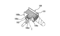
例えば、実開平2−26321号で提案されているプロテクタでは、図9に示すように、プロテクタ100内を挿通するワイヤハーネスの幹線101から支線102を分岐させて引き出す場合、幹線101の出口100aとは別に側壁100bの出口近傍に支線出口100cを設け、該支線出口100cにテープ巻き舌片100dを設け、支線102とテープ巻き舌片100dとに粘着テープTを巻き付けて支線出口100cに固定している。
For example, in the protector proposed in Japanese Utility Model Laid-Open No. 2-26321, as shown in FIG. 9, when the
前記のように、支線102を分岐して引き出すために、テープ巻き舌片100dを備えた支線出口100cを側壁100bから突設して設けると、プロテクタ100の形状が複雑化および大型化し、設置スペースの制約を受けやすくなる等の問題がある。
かつ、車種によっては支線102を幹線101から分岐しない場合もある。該場合にはプロテクタ100を共用化すると、突出した支線出口の存在により無駄なスペースをとることとなる。
As described above, in order to branch and pull out the
In addition, depending on the vehicle type, the
前記したプロテクタの側壁に支線出口に設ける代わりに、プロテクタの出口部分に仕切壁を立設して通路を分割し、各通路の出口にそれぞれテープ巻き舌片を設ける場合がある。該構成とすると、側壁に支線出口を突設するよりプロテクタの小型化が図れる利点がある。 Instead of providing the branch line outlet on the side wall of the protector described above, a partition wall may be erected at the outlet portion of the protector to divide the passage, and a tape winding tongue may be provided at the outlet of each passage. With this configuration, there is an advantage that the protector can be downsized rather than the branch line outlet projecting from the side wall.
例えば、図10(A)(B)に示すように、異なる配索経路をとる第1電線群120と、第2電線群121とをプロテクタ130に通す場合、プロテクタ130の出入口にそれぞれ仕切壁130a、130bを底壁130cから立設して、2つの分割した電線通路131と132を設けている。また、各通路毎に出入口に底壁の開口端からテープ巻き舌片131aと131b、132aと132bを隣接して並ぶように突設している。
For example, as shown in FIGS. 10A and 10B, when the
このように、入口側でテープ巻き舌片131a、132aが隣接して並び、出口側でもテープ巻き舌片131b、132bが隣接して並ぶと、一方にテープ巻き作業する際、他方が干渉して非常にやりにくくなる。特に、一方のテープ巻き舌片にワイヤハーネス組立時に電線群を通してテープ巻きし、他方には自動車組立ラインで電線群を挿通してテープ巻きする場合等、テープ巻き作業が別工程でなされる場合、先にテープ巻きされている部分が後からのテープ巻き作業時に干渉して、巻き付けが非常に困難となる。
As described above, when the
また、図10(C)に示すように、車種によっては、一方の通路131にのみ第1電線群120を挿通し、通路132には第2電線群121を挿通しない場合がある。
さらに、図10(D)に示すように、通路131に挿入し、中間位置で経路変更して通路132から引き出す場合もある。
図10(C)(D)に示すように、並列する2つのテープ巻き舌片のうち、一方のテープ巻き舌片とのみに電線群をテープ巻きする場合、他方のテープ巻き舌片は不要となり、かつ、不要であるがテープ巻き舌片が並んでいるため、一方のテープ巻き舌片へのテープ巻き作業がやりにくい問題がある。
In addition, as shown in FIG. 10C, depending on the vehicle model, the
Furthermore, as shown in FIG. 10 (D), it may be inserted into the
As shown in FIGS. 10C and 10D, when the electric wire group is tape-wound only with one tape winding tongue piece among the two tape winding tongue pieces arranged in parallel, the other tape winding tongue piece becomes unnecessary. And since it is unnecessary, since the tape winding tongue piece is located in a line, there exists a problem that the tape winding operation | work to one tape winding tongue piece is difficult to do.
本発明は前記問題に鑑みてなされたもので、プロテクタ内に仕切壁を設けて通路を分割している場合に、各通路の底壁からテープ巻き舌片を並べて突設することなしに、両方の通路に電線群を挿通する場合、いずれか一方の通路に電線群を挿通する場合、別工程で両方の通路に電線群を挿通する場合など、種々の形態に対応できワイヤハーネスのプロテクタへの固定作業が容易に出来るようにすることを課題としている。 The present invention has been made in view of the above problems, and in the case where a partition wall is provided in the protector to divide the passages, both of them are provided without protruding tape-wrapped tongues side by side from the bottom wall of each passage. When the wire group is inserted into one of the passages, when the wire group is inserted into one of the passages, or when the wire group is inserted into both passages in a separate process, the wire harness protector can be applied to various forms. The task is to make the fixing work easy.
前記課題を解決するため、本発明は、底壁と、該底壁の幅方向の両端縁から突出する側壁とで電線通路を形成しているプロテクタであって、
前記底壁の長さ方向の先端側に電線通路を仕切る仕切壁を立設し、該仕切壁を先端より外方へ延在させて、電線群固定用の固定片を設け、前記仕切られた電線通路の底壁の開口端から固定片を突出させていないことを特徴とするワイヤハーネス用プロテクタを提供している。
In order to solve the above problems, the present invention is a protector in which an electric wire passage is formed by a bottom wall and side walls protruding from both end edges in the width direction of the bottom wall,
A partition wall that divides the electric wire passage is erected on the distal end side in the length direction of the bottom wall, the partition wall extends outward from the distal end, a fixing piece for fixing the electric wire group is provided, and the partitioned A protector for a wire harness is provided in which a fixed piece is not protruded from an opening end of a bottom wall of an electric wire passage.
前記のように、本発明のプロテクタは、電線通路を仕切る仕切壁を利用し、該仕切壁をプロテクタの長さ方向先端から外方に突出させて延在し、テープ巻き舌片あるいは締結バンド用取付片となる固定片を設けている。
前記固定片を締結バンド用取付片とする場合は、バンド通し穴を設け、該バント通し穴に締結バンドを通して電線群と締結している。テープ巻きする場合は、固定片と電線群とを粘着テープを巻き付けて取り付けている。
As described above, the protector of the present invention uses the partition wall that partitions the electric wire passage, and extends the partition wall so as to protrude outward from the longitudinal end of the protector. A fixing piece is provided as an attachment piece.
When the fixing piece is an attachment piece for a fastening band, a band through hole is provided, and the band is fastened to the electric wire group through the fastening band. When winding the tape, the fixing piece and the electric wire group are attached by winding an adhesive tape.
本発明のプロテクタでは、両側の電線通路に電線群が挿通される場合には、両側の電線群に1本の締結バンドのバンド片を巻き付けて締結固定し、または粘着テープを前記固定片を挟んで両側の電線群の外周を連続して巻き付けて同時にテープ巻きで固定し、
また、前記固定片のいずれか一方の片側の電線通路の電線群を締結バンド粘着テープで固定している。
In the protector of the present invention, when a wire group is inserted into the wire passages on both sides, a band piece of one fastening band is wound and fastened around the wire groups on both sides, or an adhesive tape is sandwiched between the fixing pieces. Then, continuously wind the outer circumference of the wire group on both sides and fix it with tape.
Moreover, the electric wire group of the electric wire channel | path of any one side of the said fixing piece is being fixed with the fastening band adhesive tape.
このように、本発明では、プロテクタの底壁からテープ巻き舌片からなる固定片を隣接して並べておらず、仕切壁により分割された通路の境界位置に仕切壁を延在させて形成した固定片を設けている。両側通路の境界位置から固定片が突出するため、両側の通路に挿通させる電線群を1つの固定片を用いて固定でき、かつ、いずれか一方の通路にのみ電線群を挿通させる場合にも、該固定片を用いて電線群を固定することができる。
また、従来の底壁から並べてテープ巻き舌片を突設する場合に生じるテープ巻き作業のやりにくさを解消できる。
As described above, in the present invention, the fixing pieces formed of the tape-wrapped tongue pieces are not arranged adjacent to the bottom wall of the protector, but are formed by extending the partition walls at the boundary positions of the passages divided by the partition walls. A piece is provided. Since the fixing piece protrudes from the boundary position of the both-side passage, the electric wire group to be inserted into the passage on both sides can be fixed using one fixing piece, and when the electric wire group is inserted only into one of the passages, The wire group can be fixed using the fixing piece.
In addition, it is possible to eliminate the difficulty of performing the tape winding operation that occurs when the tape winding tongue piece is provided side by side from the conventional bottom wall.
なお、プロテクタは1つの仕切壁により2つの通路に分割する場合に限定されず、2つの仕切壁を設けて3つの通路に分割する場合、さらに、3つの仕切壁を設けて4つの通路の分割する場合等においても、仕切壁を開口端から延長して固定片とすれば良い。 The protector is not limited to dividing into two passages by one partition wall, and when dividing into three passages by providing two partition walls, further dividing into four passages by providing three partition walls. In such a case, the partition wall may be extended from the opening end to be a fixed piece.
さらに、本発明は、底壁と、該底壁の幅方向の両端縁から突出する側壁とで電線通路を形成しているプロテクタであって、
前記底壁の長さ方向の先端側に電線通路を仕切る仕切壁を立設していると共に、前記両側の側壁の長さ方向の先端を外方へ延在させて固定片とし、前記底壁の開口端から前記仕切壁を挟んで固定片を突出させていないことを特徴とするワイヤハーネス用プロテクタを提供している。
Furthermore, the present invention is a protector in which an electric wire passage is formed by a bottom wall and side walls protruding from both end edges in the width direction of the bottom wall,
A partition wall for partitioning the electric wire passage is erected on the distal end side in the length direction of the bottom wall, and the distal ends in the length direction of the side walls on both sides are extended outward to form a fixed piece, There is provided a protector for a wire harness characterized in that no fixed piece is projected from the opening end of the door with the partition wall interposed therebetween.
前記構成のプロテクタでは、固定片は両側の側壁を突設して設けているため、両側の固定片は離れて位置し、一方の固定片に電線群をテープ巻きまたは締結バンドを巻き付けて固定する作業時に、他方の固定片は干渉せず、作業性良く電線群を固定することができる。
なお、前記固定片は側壁のみから突設した平板状としても良いし、該側壁に沿った底壁の隅部も延在させ、断面L形状の固定片としてもよい。この場合にも、底壁から突設させる部分は寸法をあけているため、一方の固定片へのワイヤハーネス取り付け時に他方側の固定片が邪魔になることはない。
In the protector having the above-described configuration, since the fixing pieces are provided by protruding the side walls on both sides, the fixing pieces on both sides are located apart from each other, and the electric wire group is fixed to one fixing piece by winding a tape or a fastening band. During the work, the other fixing piece does not interfere, and the electric wire group can be fixed with good workability.
The fixing piece may be a flat plate projecting only from the side wall, or may be a fixing piece having an L-shaped cross section by extending the corner of the bottom wall along the side wall. Also in this case, since the portion protruding from the bottom wall is dimensioned, the other fixing piece does not get in the way when the wire harness is attached to one fixing piece.
本発明のいずれのプロテクタにおいても、仕切壁は底壁の長さ方向の両側に立設し、該両側の仕切壁に前記固定片を突設して設け、かつ、底壁の中央部分には仕切壁を設けずに電線群の通路変更を可能としていることが好ましい。
また、前記プロテクタには、上面開口を閉鎖する蓋を被せても良いし、プロテクタの外周にテープを巻き付けて、上面をテープで覆い、プロテクタ内部に収容した電線群の飛び出しを巻き付けたテープで防止してもよい。
蓋を設ける場合には、前記プロテクタと一体に樹脂成形し、薄肉ヒンジ部を介して蓋を連結しても良いし、蓋は別体として成形してもよい。
In any of the protectors of the present invention, the partition wall is erected on both sides in the length direction of the bottom wall, the fixing pieces are provided so as to project from the partition walls on both sides, and the central portion of the bottom wall is provided. It is preferable that the passage of the electric wire group can be changed without providing a partition wall.
In addition, the protector may be covered with a lid that closes the upper surface opening, or the tape is wrapped around the outer periphery of the protector, the upper surface is covered with the tape, and the tape that prevents the wire group housed inside the protector from being wrapped is prevented. May be.
When a lid is provided, the lid may be molded integrally with the protector, and the lid may be connected via a thin hinge, or the lid may be molded separately.
上述したように、本発明の通路分割する仕切壁を設けたプロテクタにおいて、通路毎に底壁の開口端からテープ巻き舌片を突設する代わりに、仕切壁を開口端から外方へ延在させて固定片としているため、両側の通路に電線群を挿通する場合、いずれか一方の通路にのみ電線群を挿通する場合において、該固定片を用いて電線群をテープ巻き又は締結バンドで固定する際に、作業性良くプロテクタに固定することができる。 As described above, in the protector provided with the partition wall for dividing the passage of the present invention, the partition wall extends outward from the opening end instead of protruding the tape winding tongue piece from the opening end of the bottom wall for each passage. Because it is a fixed piece, when the wire group is inserted into the passages on both sides, when the wire group is inserted through only one of the passages, the wire group is fixed with tape or a fastening band using the fixed piece Can be fixed to the protector with good workability.
また、側壁を延在させて固定片を突設する場合には、側壁間は比較的大きな寸法があいているため、一方の固定片への電線群の取り付け時に、他方の固定片が邪魔になることを防止できる。 In addition, when the fixed piece is projected with the side wall extended, the relatively large size is provided between the side walls. Therefore, when the electric wire group is attached to one fixed piece, the other fixed piece is obstructive. Can be prevented.
以下、本発明のプロテクタの実施形態を図面を参照して説明する。
図1乃至図5に第一実施形態のプロテクタを示す。
Hereinafter, embodiments of a protector of the present invention will be described with reference to the drawings.
The protector of 1st embodiment is shown in FIG. 1 thru | or FIG.
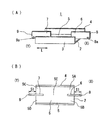
プロテクタ1は樹脂成形品からなり、図1(A)(B)に示すように、底壁2と、該底壁2の幅方向の両端縁から突出する側壁3、4とで電線通路5を形成しており、長さ方向Lが長い樋形状としている。
底壁2の長さ方向Lの両端側に電線通路5を仕切る仕切壁6、7を立設している。プロテクタ1の入口Xの仕切壁6で、電線通路5を第一入口側通路5A、第二入口側通路5Bに分割している。出口Yの仕切壁7で、電線通路5を第一出口側通路5C、第二出口側通路5Dに分割している。プロテクタの長さ方向の中間部では仕切壁6、7を設けずに経路変更通路5Eとしている。
The
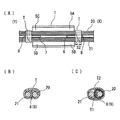
前記仕切壁6、7は入口X、出口Yの両方で底壁先端より外方に延在させて突出し、入口側の固定片8、出口側の固定片9としている。これら固定片8、9の突出量S1は巻き付ける粘着テープ10の幅S2以上とし、本実施形態では20mmとしている。該固定片8、9は樹脂成形時に一体成形で設けている。
The
また、固定片8、9には締結バンドで電線群を取り付ける場合も利用できるように、バンド通し穴8a、9aを設けている。
Further, the through-
本実施形態のプロテクタ1は上面開口を閉鎖する蓋を設けずに、電線群を通した後にプロテクタ1の外周に粘着テープを巻き付けて、電線通路5に通した電線群が上面開口から飛び出さないようにしている。
なお、蓋付きとし、プロテクタ1の一方の側壁3または4に薄肉ヒンジ部を介して一体成形しても良いし、蓋を別体で設けてプロテクタ1に被せて結合してもよい。
The
In addition, it may be provided with a lid, and may be integrally formed on one
前記プロテクタ1は、図2〜図5に示す電線群の配索のいずれにも対応でき、前記固定片8、9を用いて、電線群をプロテクタ1に固定することができる。
The
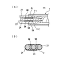
図2(A)〜(C)では、第一入口側通路5Aから挿入し、経路変更せずに、第一出口側通路5Cより引き出す第一電線群20と、第二入口側通路5Bから挿入し、経路変更せずに第二出口側通路5Dより引き出す第二電線群21とをプロテクタ1に挿通している。
この場合、第一電線群20と第二電線群21とは入口X側で固定片8を挟んで配置し、粘着テープTをこれら第一電線群20、固定片8、第二電線群21の外周に連続して巻き付けて、プロテクタ1に第一、第二電線群20、21を同時にテープ巻き固定している。出口Y側でも同様として、固定片9を挟んで、第一、第二電線群20、21を粘着テープTを連続して巻き付けて同時に固定している。
In FIGS. 2A to 2C, the first
In this case, the first
第一電線群20がワイヤハーネス組立工場でプロテクタ1に通されて、第二電線群21が自動車組立工場でプロテクタ1に通され、別工程でプロテクタへ電線群をテープ巻きで固定する必要がある。この場合、図2(C)に示すように、第一電線群20と固定片8に巻き付けた粘着テープT1の外周に、第二電線群21に巻き付ける粘着テープT2を巻き付けている。このように粘着テープT2を巻き付けると、後工程の電線群のテープ巻き作業が容易となる。
The first
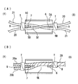
図3(A)では、第一電線群20のみを第一入口側通路5Aと出口側通路5Cに挿通し、第二電線群21はプロテクタ1に通していない。この場合、該第一電線群20のみを入口X、出口Yで固定片8、9の片面にそれぞれ押し当てて粘着テープTを巻き付けて固定している。
第二電線群21のみをプロテクタ1に挿通し、第一電線群20を挿通していない場合も同様である。
In FIG. 3A, only the first
The same applies to the case where only the second
図3(B)では、図3(A)と同様に、第一電線群20のみを挿通しているが、第一入口側通路5Aを通し、経路変更部5Eで経路変更し、第二入口側通路5Dから引き出している。この場合も、入口Xでは固定片8の図中左面に第一電線群20を押し当てて粘着テープTを巻き付けて固定し、出口Yでは固定片9の図中右面に第一電線群20を押し当てて粘着テープTを巻き付けて固定している。
第二電線群21を第二入口側通路5Bを通し経路変更して第一出口側通路5Cから引き出す場合も同様である。
In FIG. 3 (B), only the
The same applies to the case where the
図4(A)では、第一電線群20と第二電線群21の両方を経路変更部5Eで経路変更しており、この場合は、図2と同様に、入口Xおよび出口Yで固定片8、9を挟んで両側の第一、第二電線群20、21を1回の粘着テープの巻き付けで同時に固定している。
In FIG. 4A, both the first
図4(B)では、第一電線群20を第一入口側通路5Aに通し、経路変更部5Eで分岐させ、一方の分岐線20aを第一出口側通路5Cから引き出し、他方の分岐線20bを第二出口側通路5Dから引き出している。この場合、入口Xでは固定片8の図中左側に押し上げて粘着テープTを巻き付けて固定し、出口Yでは固定片9を挟んで両側の分岐線20a、20bを配置し、連続して粘着テープTを巻き付けて同時に固定している。
In FIG. 4B, the first
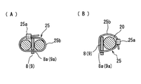
図5(A)(B)は、粘着テープTを用いず、締結バンド25を用いて固定している。 締結バンド25は、係止穴を設けた締結部25aの一面側から鋸歯状の係止溝を設けたバンド片25bが突設し、該バンド片25bを締結部25aの係止穴に通し、係止穴の内面から突設した係止片を前記係止溝に係止して締結固定する汎用品からなる。
該締結バンド25のバンド片25bを固定片8、9に設けているバンド通し穴8a、9aに通し、電線群に巻き付けた後に締結部25bにバンド片25aを通して係止固定している。
5A and 5B, the adhesive tape T is not used, but the
The
図5(A)では、固定片8(9)に第一電線群20と第二電線群21とをバンド片25bを連続的に巻き付けて、同時に締結バンド26で締結している。
図5(B)では、固定片8(9)に第一電線群20のみ(あるいは第二電線群21のみ)を片面に押し当て、締結バンド25で締結固定している。
In FIG. 5A, the first
In FIG. 5B, only the first electric wire group 20 (or only the second electric wire group 21) is pressed against one surface of the fixed piece 8 (9) and fastened and fixed by the
このように、電線通路の境界に位置する仕切壁6、7を外方に延在させて固定片8、9を設けることにより、従来は各通路の入口、及び出口にそれぞれ底壁から隣接して突設していた2つのテープ巻き舌片を、入口X、出口Yにおいてそれぞれ境界に位置する1つの固定片8、9を設ければ良いだけとなる。また、テープ巻き時または締結バンドのバンド片の巻付時に、隣接する他の電線群巻付片が無いため、巻付作業姓を高めることができる。
In this manner, by providing the fixing
図6(A)(B)に第一実施形態の変形例を示す。
変形例のプロテクタ1では、図6(A)に示すように、出口Y側では、底壁2から間隔をあけて2つの仕切壁7−1、7−2を突設し、電線通路5の出口側で3つの出口側通路5L、5M、5Nに分けている。
この場合も、2つの仕切壁7−1、7−2をそれぞれ延在して固定片9M、9Nを突設している。
6A and 6B show a modification of the first embodiment.
In the
Also in this case, the two partition walls 7-1 and 7-2 are extended, and the fixing
各出口側通路5L、5M、5Nに電線群22、23、24を通す場合、図6(B)に示すように、固定片9Mと9Nに挟まれた出口側通路5Mの電線群23と、固定片9M、9Nの他面側の出口側通路5L、5Nの電線群22、24との3組の電線群を、固定片9M、9Nを含めて、粘着テープTを連続して巻き付け、1回の巻き付け作業で3組の電線群22〜24をプロテクタに固定している。
隣接する出口側通路5Lと5Mまたは5Mと5Nに2組の電線群を通す場合には、第一実施形態と同様に2組の電線群を粘着テープの1回の巻き付け作業で固定片9Mまたは9Nも固定している。
なお、入口側にも複数の仕切壁を突設し、これら仕切壁からそれぞれ固定片を突設しても良いことは言うまでもない。
When passing the
When passing two sets of electric wire groups through the adjacent
Needless to say, a plurality of partition walls may be provided on the inlet side, and fixed pieces may be provided from the partition walls.
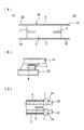
図7(A)〜(C)に第二実施形態を示す。
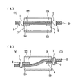
第二実施形態のプロテクタ30と前記第一実施形態のプロテクタ1との相違点は、第二実施形態では仕切壁6、7より固定片を突設させず、側壁3、4を外方に延在させて突出し、入口X側に固定片31、32、出口Y側に固定片33、34としている点である。
他の構成は第一実施形態と同一符号を付して説明を省略する。
7A to 7C show a second embodiment.
The difference between the
Other configurations are denoted by the same reference numerals as those in the first embodiment, and description thereof is omitted.
本第二実施形態では、図7(C)に示すように、第一電線群20は入口X、出口Yでそれぞれ固定片31、33と粘着テープTを巻き付けて固定している。第二電線群21も同様に固定片32、34とテープ巻きしている。このように、テープ巻き作業は各電線群毎に行われ、テープ巻き作業回数を減少していないが、側壁3、4を延在して設ける固定片31と32、33と34の間の寸法S3は大きいため、テープ巻き作業時に干渉しない。
In the second embodiment, as shown in FIG. 7C, the first
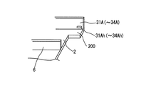
なお、図8に示すように、側壁3(4)に近接部分の底壁2にも突出部200を設け、L形状の固定片31A(〜34A)としてもよい。
さらに、前記固定片31A〜34Aに、第一実施形態と同様に、締結バンド取付用の通し穴31Ah(〜34Ah)を設けてもよい。
In addition, as shown in FIG. 8, it is good also as the L-shaped
Furthermore, the fixing
1 プロテクタ
2 底壁
3、4 側壁
5 電線通路
6、7 仕切壁
8、9 固定片
8a、9a 締結バンドの通し穴
20 第一電線群
21 第二電線群
25 締結バンド
DESCRIPTION OF
Claims (3)
前記底壁の長さ方向の先端側に電線通路を仕切る仕切壁を立設し、該仕切壁を先端より外方へ延在させて、電線群固定用の固定片を設け、前記仕切られた電線通路の底壁の開口端から固定片を突出させていないことを特徴とするワイヤハーネス用プロテクタ。 A protector that forms an electric wire passage with a bottom wall and side walls protruding from both end edges in the width direction of the bottom wall,
A partition wall for partitioning the electric wire passage is erected on the distal end side in the length direction of the bottom wall, the partition wall extends outward from the distal end, a fixing piece for fixing the electric wire group is provided, and the partitioned A protector for a wire harness, wherein a fixed piece is not projected from an opening end of a bottom wall of an electric wire passage.
かつ、前記固定片の両側の電線通路に電線群が挿通される場合には、両側の電線群に1本の締結バンドのバンド片を巻き付けて締結固定し、または粘着テープを前記固定片を挟んで両側の電線群の外周を連続して巻き付けて同時にテープ巻きで固定し、
また、前記固定片のいずれか一方の片側の電線通路の電線群を締結バンド粘着テープで固定している請求項1に記載のワイヤハーネス用プロテクタ。 A band through hole is provided in the fixed piece, and the band through hole is fastened to the electric wire group through a fastening band, or an adhesive tape is wound around the fixed piece and the electric wire group,
And when an electric wire group is inserted in the electric wire channel | path of the both sides of the said fixed piece, the band piece of one fastening band is wound around the electric wire group of both sides, it fastens and fixes, or the adhesive tape is pinched | interposed into the said fixed piece Then, continuously wind the outer circumference of the wire group on both sides and fix it with tape.
Moreover, the protector for wire harnesses of Claim 1 which is fixing the electric wire group of the electric wire channel | path of either one side of the said fixing piece with the fastening band adhesive tape.
前記底壁の長さ方向の先端側に電線通路を仕切る仕切壁を立設していると共に、前記両側の側壁の長さ方向の先端を外方へ延在させて電線群固定用の固定片を設け、前記底壁の開口端から前記仕切壁を挟んで固定片を突出させていないことを特徴とするワイヤハーネス用プロテクタ。 A protector that forms an electric wire passage with a bottom wall and side walls protruding from both end edges in the width direction of the bottom wall,
A partition wall for partitioning the electric wire passage is provided on the distal end side in the length direction of the bottom wall, and the distal ends in the length direction of the side walls on both sides extend outward to fix the wire group. And a fixing piece is not protruded from the opening end of the bottom wall across the partition wall.
Priority Applications (1)
| Application Number | Priority Date | Filing Date | Title |
|---|---|---|---|
| JP2008211041A JP5131087B2 (en) | 2008-08-19 | 2008-08-19 | Wire harness protector |
Applications Claiming Priority (1)
| Application Number | Priority Date | Filing Date | Title |
|---|---|---|---|
| JP2008211041A JP5131087B2 (en) | 2008-08-19 | 2008-08-19 | Wire harness protector |
Publications (2)
| Publication Number | Publication Date |
|---|---|
| JP2010051064A true JP2010051064A (en) | 2010-03-04 |
| JP5131087B2 JP5131087B2 (en) | 2013-01-30 |
Family
ID=42067679
Family Applications (1)
| Application Number | Title | Priority Date | Filing Date |
|---|---|---|---|
| JP2008211041A Expired - Fee Related JP5131087B2 (en) | 2008-08-19 | 2008-08-19 | Wire harness protector |
Country Status (1)
| Country | Link |
|---|---|
| JP (1) | JP5131087B2 (en) |
Cited By (3)
| Publication number | Priority date | Publication date | Assignee | Title |
|---|---|---|---|---|
| JP4842405B1 (en) * | 2011-03-29 | 2011-12-21 | 株式会社ミハマ | Tightening band |
| JP2014229571A (en) * | 2013-05-27 | 2014-12-08 | 株式会社オートネットワーク技術研究所 | Method of producing wire harness |
| JP2017011818A (en) * | 2015-06-18 | 2017-01-12 | 株式会社オートネットワーク技術研究所 | Wire module and wire protection member |
Citations (3)
| Publication number | Priority date | Publication date | Assignee | Title |
|---|---|---|---|---|
| JP2000215736A (en) * | 1999-01-21 | 2000-08-04 | Sumitomo Wiring Syst Ltd | Wire harness for automobile |
| JP2005229685A (en) * | 2004-02-10 | 2005-08-25 | Yazaki Corp | Wire harness accommodation holding device |
| JP2008123794A (en) * | 2006-11-10 | 2008-05-29 | Yazaki Corp | Connector push-in protector |
-
2008
- 2008-08-19 JP JP2008211041A patent/JP5131087B2/en not_active Expired - Fee Related
Patent Citations (3)
| Publication number | Priority date | Publication date | Assignee | Title |
|---|---|---|---|---|
| JP2000215736A (en) * | 1999-01-21 | 2000-08-04 | Sumitomo Wiring Syst Ltd | Wire harness for automobile |
| JP2005229685A (en) * | 2004-02-10 | 2005-08-25 | Yazaki Corp | Wire harness accommodation holding device |
| JP2008123794A (en) * | 2006-11-10 | 2008-05-29 | Yazaki Corp | Connector push-in protector |
Cited By (3)
| Publication number | Priority date | Publication date | Assignee | Title |
|---|---|---|---|---|
| JP4842405B1 (en) * | 2011-03-29 | 2011-12-21 | 株式会社ミハマ | Tightening band |
| JP2014229571A (en) * | 2013-05-27 | 2014-12-08 | 株式会社オートネットワーク技術研究所 | Method of producing wire harness |
| JP2017011818A (en) * | 2015-06-18 | 2017-01-12 | 株式会社オートネットワーク技術研究所 | Wire module and wire protection member |
Also Published As
| Publication number | Publication date |
|---|---|
| JP5131087B2 (en) | 2013-01-30 |
Similar Documents
| Publication | Publication Date | Title |
|---|---|---|
| JP5353908B2 (en) | Wire harness protector | |
| JP5768379B2 (en) | Protector for wire harness | |
| JP5772405B2 (en) | Corrugated tube with path maintenance member and wire harness | |
| JP2009065798A (en) | Wire harness protector | |
| US9463757B2 (en) | Electric junction box | |
| US9362732B2 (en) | Corrugated tube with path-maintaining member and wire harness | |
| JP2013055814A (en) | Wiring harness external packaging body | |
| US6843276B2 (en) | Corrugated tube and method for producing the same | |
| JP5136287B2 (en) | Wire harness protector | |
| WO2017110471A1 (en) | Protector for wire harness | |
| JP5131087B2 (en) | Wire harness protector | |
| JP5668613B2 (en) | Corrugated tube with path maintenance member and wire harness | |
| JP5924240B2 (en) | Protector for wire harness | |
| JP2006320096A (en) | Protector passing structure of wire harness | |
| JP5510064B2 (en) | Protector for wire harness | |
| WO2017073381A1 (en) | Exterior material for wire harness | |
| JP5267353B2 (en) | Wire harness protector | |
| JP5083177B2 (en) | Protector | |
| JP5215163B2 (en) | Electrical junction box and electric wire routing method for electrical junction box | |
| JPH10336844A (en) | Electrical junction box | |
| JP2017212802A (en) | Protective texture for wiring harness | |
| JP2009273279A (en) | Holder for wire harness | |
| JP2016111790A (en) | Exterior material for wiring harness | |
| JP7388851B2 (en) | Protector and wire harness | |
| JP7290421B2 (en) | Electric connection box manufacturing method |
Legal Events
| Date | Code | Title | Description |
|---|---|---|---|
| A621 | Written request for application examination |
Free format text: JAPANESE INTERMEDIATE CODE: A621 Effective date: 20101117 |
|
| A977 | Report on retrieval |
Free format text: JAPANESE INTERMEDIATE CODE: A971007 Effective date: 20111228 |
|
| A131 | Notification of reasons for refusal |
Free format text: JAPANESE INTERMEDIATE CODE: A131 Effective date: 20120731 |
|
| A521 | Written amendment |
Free format text: JAPANESE INTERMEDIATE CODE: A523 Effective date: 20120914 |
|
| TRDD | Decision of grant or rejection written | ||
| A01 | Written decision to grant a patent or to grant a registration (utility model) |
Free format text: JAPANESE INTERMEDIATE CODE: A01 Effective date: 20121009 |
|
| A01 | Written decision to grant a patent or to grant a registration (utility model) |
Free format text: JAPANESE INTERMEDIATE CODE: A01 |
|
| A61 | First payment of annual fees (during grant procedure) |
Free format text: JAPANESE INTERMEDIATE CODE: A61 Effective date: 20121022 |
|
| FPAY | Renewal fee payment (event date is renewal date of database) |
Free format text: PAYMENT UNTIL: 20151116 Year of fee payment: 3 |
|
| R150 | Certificate of patent or registration of utility model |
Free format text: JAPANESE INTERMEDIATE CODE: R150 |
|
| LAPS | Cancellation because of no payment of annual fees |