JP2010049894A - Fuel cell system and state detecting method of fuel cell - Google Patents
Fuel cell system and state detecting method of fuel cell Download PDFInfo
- Publication number
- JP2010049894A JP2010049894A JP2008212250A JP2008212250A JP2010049894A JP 2010049894 A JP2010049894 A JP 2010049894A JP 2008212250 A JP2008212250 A JP 2008212250A JP 2008212250 A JP2008212250 A JP 2008212250A JP 2010049894 A JP2010049894 A JP 2010049894A
- Authority
- JP
- Japan
- Prior art keywords
- voltage
- cell
- fuel cell
- current density
- cell group
- Prior art date
- Legal status (The legal status is an assumption and is not a legal conclusion. Google has not performed a legal analysis and makes no representation as to the accuracy of the status listed.)
- Granted
Links
Images


Classifications
-
- H—ELECTRICITY
- H01—ELECTRIC ELEMENTS
- H01M—PROCESSES OR MEANS, e.g. BATTERIES, FOR THE DIRECT CONVERSION OF CHEMICAL ENERGY INTO ELECTRICAL ENERGY
- H01M8/00—Fuel cells; Manufacture thereof
- H01M8/04—Auxiliary arrangements, e.g. for control of pressure or for circulation of fluids
- H01M8/04298—Processes for controlling fuel cells or fuel cell systems
- H01M8/04992—Processes for controlling fuel cells or fuel cell systems characterised by the implementation of mathematical or computational algorithms, e.g. feedback control loops, fuzzy logic, neural networks or artificial intelligence
-
- H—ELECTRICITY
- H01—ELECTRIC ELEMENTS
- H01M—PROCESSES OR MEANS, e.g. BATTERIES, FOR THE DIRECT CONVERSION OF CHEMICAL ENERGY INTO ELECTRICAL ENERGY
- H01M8/00—Fuel cells; Manufacture thereof
- H01M8/04—Auxiliary arrangements, e.g. for control of pressure or for circulation of fluids
- H01M8/04298—Processes for controlling fuel cells or fuel cell systems
- H01M8/04313—Processes for controlling fuel cells or fuel cell systems characterised by the detection or assessment of variables; characterised by the detection or assessment of failure or abnormal function
- H01M8/04537—Electric variables
- H01M8/04544—Voltage
- H01M8/04552—Voltage of the individual fuel cell
-
- H—ELECTRICITY
- H01—ELECTRIC ELEMENTS
- H01M—PROCESSES OR MEANS, e.g. BATTERIES, FOR THE DIRECT CONVERSION OF CHEMICAL ENERGY INTO ELECTRICAL ENERGY
- H01M8/00—Fuel cells; Manufacture thereof
- H01M8/04—Auxiliary arrangements, e.g. for control of pressure or for circulation of fluids
- H01M8/04298—Processes for controlling fuel cells or fuel cell systems
- H01M8/04313—Processes for controlling fuel cells or fuel cell systems characterised by the detection or assessment of variables; characterised by the detection or assessment of failure or abnormal function
- H01M8/04537—Electric variables
- H01M8/04574—Current
- H01M8/04582—Current of the individual fuel cell
-
- H—ELECTRICITY
- H01—ELECTRIC ELEMENTS
- H01M—PROCESSES OR MEANS, e.g. BATTERIES, FOR THE DIRECT CONVERSION OF CHEMICAL ENERGY INTO ELECTRICAL ENERGY
- H01M8/00—Fuel cells; Manufacture thereof
- H01M8/04—Auxiliary arrangements, e.g. for control of pressure or for circulation of fluids
- H01M8/04298—Processes for controlling fuel cells or fuel cell systems
- H01M8/04313—Processes for controlling fuel cells or fuel cell systems characterised by the detection or assessment of variables; characterised by the detection or assessment of failure or abnormal function
- H01M8/0432—Temperature; Ambient temperature
- H01M8/04358—Temperature; Ambient temperature of the coolant
-
- H—ELECTRICITY
- H01—ELECTRIC ELEMENTS
- H01M—PROCESSES OR MEANS, e.g. BATTERIES, FOR THE DIRECT CONVERSION OF CHEMICAL ENERGY INTO ELECTRICAL ENERGY
- H01M8/00—Fuel cells; Manufacture thereof
- H01M8/04—Auxiliary arrangements, e.g. for control of pressure or for circulation of fluids
- H01M8/04298—Processes for controlling fuel cells or fuel cell systems
- H01M8/04313—Processes for controlling fuel cells or fuel cell systems characterised by the detection or assessment of variables; characterised by the detection or assessment of failure or abnormal function
- H01M8/04664—Failure or abnormal function
- H01M8/04671—Failure or abnormal function of the individual fuel cell
-
- Y—GENERAL TAGGING OF NEW TECHNOLOGICAL DEVELOPMENTS; GENERAL TAGGING OF CROSS-SECTIONAL TECHNOLOGIES SPANNING OVER SEVERAL SECTIONS OF THE IPC; TECHNICAL SUBJECTS COVERED BY FORMER USPC CROSS-REFERENCE ART COLLECTIONS [XRACs] AND DIGESTS
- Y02—TECHNOLOGIES OR APPLICATIONS FOR MITIGATION OR ADAPTATION AGAINST CLIMATE CHANGE
- Y02E—REDUCTION OF GREENHOUSE GAS [GHG] EMISSIONS, RELATED TO ENERGY GENERATION, TRANSMISSION OR DISTRIBUTION
- Y02E60/00—Enabling technologies; Technologies with a potential or indirect contribution to GHG emissions mitigation
- Y02E60/30—Hydrogen technology
- Y02E60/50—Fuel cells
Abstract
Description
本発明は、燃料電池システム、および、燃料電池の状態検知方法に関する。 The present invention relates to a fuel cell system and a fuel cell state detection method.
燃料電池は、一般的には水素及び酸素を燃料として電気エネルギーを得る装置である。この燃料電池は、環境面において優れかつ高いエネルギー効率を実現できることから、今後のエネルギー供給システムとして広く開発が進められてきている。特に、固体高分子型燃料電池は、各種の燃料電池の中でも比較的低温で作動することから、良好な起動性を有する。そのため、多方面における実用化のために盛んに研究がなされている。 A fuel cell is a device that generally obtains electric energy using hydrogen and oxygen as fuel. Since this fuel cell is excellent in terms of environment and can realize high energy efficiency, it has been widely developed as a future energy supply system. In particular, since the polymer electrolyte fuel cell operates at a relatively low temperature among various types of fuel cells, it has a good startability. For this reason, research has been actively conducted for practical application in various fields.
固体高分子型燃料電池は、プロトン伝導性を有する固体高分子型電解質からなる電解質膜の両側に、それぞれアノードおよびカソードが設けられた膜−電極接合体(MEA:Membrane Electrode Assembly)が、セパレータによって挟持された構造を有している。 A polymer electrolyte fuel cell has a membrane-electrode assembly (MEA) in which an anode and a cathode are provided on both sides of an electrolyte membrane made of a solid polymer electrolyte having proton conductivity, respectively, by means of a separator. It has a sandwiched structure.
この燃料電池の状態は、運転条件等に応じて変化する。そこで、複数の燃料電池を積層させた燃料電池スタックにおいて、セル群ごとに測定したセル電圧の低下を監視する技術が開示されている(例えば、特許文献1参照)。 The state of the fuel cell changes according to operating conditions and the like. Therefore, a technique for monitoring a decrease in cell voltage measured for each cell group in a fuel cell stack in which a plurality of fuel cells is stacked is disclosed (for example, see Patent Document 1).
しかしながら、電圧低下を監視するだけでは、セルの状態を高い精度で検知することが困難である。また、セル群単位でセル電圧の低下が検出されているため、セル群に含まれる一部のセルの状態を高い精度で検知することが困難である。一方でセルごとにセル電圧検出手段を設けると、コストが増大してしまう。 However, it is difficult to detect the state of the cell with high accuracy only by monitoring the voltage drop. In addition, since a decrease in cell voltage is detected on a cell group basis, it is difficult to detect the state of some cells included in the cell group with high accuracy. On the other hand, if the cell voltage detecting means is provided for each cell, the cost increases.
本発明は、コスト増大を抑制しつつ高い精度で燃料電池の状態を検知可能な燃料電池システムおよび燃料電池の状態検知方法を提供することを目的とする。 An object of the present invention is to provide a fuel cell system and a fuel cell state detection method capable of detecting the state of a fuel cell with high accuracy while suppressing an increase in cost.
本発明に係る燃料電池システムは、1以上のセルを含むセル群のセル電圧を検出する電圧検出手段と、セル群の発電電流密度を検出する電流密度検出手段と、電圧検出手段および電流密度検出手段の検出結果に基づいて発電電流密度に対するセル電圧の変化の変極点が存在するか否かを判定する判定手段と、を備えることを特徴とするものである。本発明に係る燃料電池システムにおいては、対象としているセル群の変極点を検出することができる。それにより、高い精度で燃料電池の状態を検知することができる。また、セル群に複数のセルが含まれていても変極点の検出が可能であることから、セルごとに電圧検出手段を設ける必要がない。その結果、コストの低減化を図ることができる。 A fuel cell system according to the present invention includes a voltage detection unit that detects a cell voltage of a cell group including one or more cells, a current density detection unit that detects a generated current density of the cell group, a voltage detection unit, and a current density detection Determining means for determining whether or not there is an inflection point of the change of the cell voltage with respect to the generated current density based on the detection result of the means. In the fuel cell system according to the present invention, the inflection point of the target cell group can be detected. Thereby, the state of the fuel cell can be detected with high accuracy. Further, since the inflection point can be detected even if a plurality of cells are included in the cell group, it is not necessary to provide a voltage detection means for each cell. As a result, cost can be reduced.
判定手段は、所定の条件下におけるセル群のセル電圧の1次回帰電圧と電圧検出手段の検出結果との差に基づいて、変極点が存在するか否かを判定してもよい。判定手段は、セル群のセル電圧と1以上のセルを含む基準セル群の基準電圧との関係を用いて、セル群に変極点が存在するか否かを判定してもよい。判定手段は、セル群のセル電圧の電流密度に対する傾きが、基準セル群の基準電圧の電流密度に対する傾きよりも所定量大きくなった場合に、変極点が存在すると判定してもよい。 The determination means may determine whether or not an inflection point exists based on a difference between the primary regression voltage of the cell voltage of the cell group under a predetermined condition and the detection result of the voltage detection means. The determination unit may determine whether or not an inflection point exists in the cell group using a relationship between the cell voltage of the cell group and the reference voltage of the reference cell group including one or more cells. The determination unit may determine that an inflection point exists when a slope of the cell voltage of the cell group with respect to the current density is a predetermined amount greater than a slope of the reference voltage of the reference cell group with respect to the current density.
判定手段は、同一電流密度におけるセル群のセル電圧と基準セル群の基準電圧との乖離率に、変極点が存在するか否かを判定してもよい。この場合、より高い精度で変極点が存在するか否かを判定することができる。 The determination means may determine whether or not there is an inflection point in the deviation rate between the cell voltage of the cell group and the reference voltage of the reference cell group at the same current density. In this case, it can be determined whether or not the inflection point exists with higher accuracy.
判定手段は、乖離率の電流密度に対する傾きが負になった場合に、変極点が存在すると判定してもよい。判定手段は、乖離率の電流密度に対する回帰直線の切片が所定値以上になった場合に、変極点が存在すると判定してもよい。 The determination means may determine that an inflection point exists when the slope of the deviation rate with respect to the current density is negative. The determination means may determine that an inflection point exists when the intercept of the regression line with respect to the current density of the deviation rate is equal to or greater than a predetermined value.
基準セル群は、燃料電池スタックにおいて平均発電性能よりも高い発電性能を有していてもよい。基準セル群は、燃料電池スタックにおいて平均発電耐久性よりも高い発電耐久性を有していてもよい。これらの場合、変極点の検出精度が高くなる。 The reference cell group may have a power generation performance higher than the average power generation performance in the fuel cell stack. The reference cell group may have a power generation durability higher than the average power generation durability in the fuel cell stack. In these cases, the inflection point detection accuracy is increased.
本発明に係る燃料電池の状態検知方法は、1以上のセルを含むセル群のセル電圧を検出する電圧検出ステップと、セル群の発電電流密度を検出する電流密度検出ステップと、電圧検出ステップおよび電流密度検出ステップにおける検出結果に基づいて発電電流密度に対するセル電圧の変化の変極点が存在するか否かを判定する判定ステップと、を含むことを特徴とするものである。本発明に係る燃料電池の状態検知方法においては、対象としているセル群の変極点を検出することができる。それにより、高い精度で燃料電池の状態を検知することができる。また、セル群に複数のセルが含まれていても変極点の検出が可能であることから、セルごとに電圧検出手段を設ける必要がない。その結果、コストの低減化を図ることができる。 A fuel cell state detection method according to the present invention includes a voltage detection step for detecting a cell voltage of a cell group including one or more cells, a current density detection step for detecting a generated current density of the cell group, a voltage detection step, and And a determination step of determining whether or not there is an inflection point of a change in the cell voltage with respect to the generated current density based on a detection result in the current density detection step. In the fuel cell state detection method according to the present invention, the inflection point of the target cell group can be detected. Thereby, the state of the fuel cell can be detected with high accuracy. Further, since the inflection point can be detected even if a plurality of cells are included in the cell group, it is not necessary to provide a voltage detection means for each cell. As a result, cost can be reduced.
判定ステップは、所定の条件下におけるセル群のセル電圧の1次回帰電圧と電圧検出ステップにおける検出結果との差に基づいて、変極点が存在するか否かを判定するステップであってもよい。判定ステップは、セル群のセル電圧と1以上のセルを含む基準セル群の基準電圧との関係を用いて、セル群に変極点が存在するか否かを判定するステップであってもよい。判定ステップは、セル群のセル電圧の電流密度に対する傾きが、基準セル群の基準電圧の電流密度に対する傾きよりも所定量大きくなった場合に、変極点が存在すると判定するステップであってもよい。 The determination step may be a step of determining whether or not an inflection point exists based on a difference between the primary regression voltage of the cell voltage of the cell group under a predetermined condition and the detection result in the voltage detection step. . The determination step may be a step of determining whether or not an inflection point exists in the cell group using a relationship between the cell voltage of the cell group and the reference voltage of the reference cell group including one or more cells. The determination step may be a step of determining that an inflection point exists when the slope of the cell voltage of the cell group with respect to the current density is larger than the slope of the reference voltage of the reference cell group with respect to the current density. .
判定ステップは、同一電流密度におけるセル群のセル電圧と基準セル群の基準電圧との乖離率に、変極点が存在するか否かを判定するステップであってもよい。この場合、より高い精度で変極点が存在するか否かを判定することができる。 The determination step may be a step of determining whether or not an inflection point exists in the deviation rate between the cell voltage of the cell group and the reference voltage of the reference cell group at the same current density. In this case, it can be determined whether or not the inflection point exists with higher accuracy.
判定ステップは、乖離率の電流密度に対する傾きが負になった場合に、変極点が存在すると判定するステップであってもよい。判定ステップは、乖離率の電流密度に対する回帰直線の切片が所定値以上になった場合に、変極点が存在すると判定するステップであってもよい。 The determination step may be a step of determining that an inflection point exists when the slope of the deviation rate with respect to the current density is negative. The determination step may be a step of determining that an inflection point exists when the intercept of the regression line with respect to the current density of the deviation rate is equal to or greater than a predetermined value.
基準セル群は、燃料電池スタックにおいて平均発電性能よりも高い発電性能を有していてもよい。基準セル群は、燃料電池スタックにおいて平均発電耐久性よりも高い発電耐久性を有していてもよい。これらの場合、変極点の検出精度が高くなる。 The reference cell group may have a power generation performance higher than the average power generation performance in the fuel cell stack. The reference cell group may have a power generation durability higher than the average power generation durability in the fuel cell stack. In these cases, the inflection point detection accuracy is increased.
本発明によれば、高い精度で燃料電池の状態を検知することができる。 According to the present invention, the state of the fuel cell can be detected with high accuracy.
以下、本発明を実施するための最良の形態を説明する。 Hereinafter, the best mode for carrying out the present invention will be described.
図1は、本発明の第1実施例に係る燃料電池システム100を説明するための図である。図1(a)は、燃料電池システム100の全体構成を示す模式図である。図1(b)は、後述するセル11の模式的断面図である。図1(a)に示すように、燃料電池システム100は、燃料電池スタック10、燃料ガス供給手段20、酸化剤ガス供給手段30、電圧検出手段41、電流検出手段42および処理部50等を備える。
FIG. 1 is a diagram for explaining a fuel cell system 100 according to a first embodiment of the present invention. FIG. 1A is a schematic diagram showing the overall configuration of the fuel cell system 100. FIG.1 (b) is typical sectional drawing of the
燃料電池スタック10は、1または複数のセル11が積層されたセル群が1または複数積層された構造を有する。図1(b)に示すように、セル11は、膜−電極接合体110がセパレータ120およびセパレータ130によって挟持された構造を有する。膜−電極接合体110は、電解質膜111のセパレータ120側にアノード触媒層112およびガス拡散層113が順に接合され、電解質膜111のセパレータ130側にカソード触媒層114およびガス拡散層115が順に接合された構造を有する。電解質膜111は、プロトン伝導性を有するパーフルオロスルフォン酸型ポリマー等の固体高分子電解質からなる。
The
アノード触媒層112は、触媒を担持する導電性材料、プロトン伝導性電解質等から構成される。アノード触媒層112における触媒は、水素のプロトン化を促進するための触媒である。例えば、アノード触媒層112は、白金担持カーボン、パーフルオロスルフォン酸型ポリマー等を含む。ガス拡散層113は、カーボンペーパ、カーボンクロス等のガス透過性を有する導電性材料からなる。
The
カソード触媒層114は、触媒を担持する導電性材料、プロトン伝導性電解質等から構成される。カソード触媒層114は、プロトンと酸素との反応を促進するための触媒である。例えば、カソード触媒層114は、白金担持カーボン、パーフルオロスルフォン酸型ポリマー等を含む。ガス拡散層115は、カーボンペーパ、カーボンクロス等のガス透過性を有する導電性材料からなる。
The
セパレータ120,130は、ステンレス等の導電性材料から構成される。セパレータ120の膜−電極接合体110側の面には、燃料ガスが流動するための燃料ガス流路121が形成されている。セパレータ130の膜−電極接合体110側の面には、酸化剤ガスが流動するための酸化剤ガス流路131が形成されている。例えば、燃料ガス流路121および酸化剤ガス流路131は、セパレータの表面に形成された凹部からなる。
Separator 120,130 is comprised from electroconductive materials, such as stainless steel. On the surface of the
燃料ガス供給手段20は、燃料電池スタック10の燃料ガス入口を介して燃料ガス流路121に、水素を含有する燃料ガスを供給する装置である。燃料ガス供給手段20は、例えば、水素ボンベ、改質器等からなる。酸化剤ガス供給手段30は、燃料電池スタック10の酸化剤ガス入口を介して酸化剤ガス流路131に、酸素を含有する酸化剤ガスを供給する装置である。酸化剤ガス供給手段30は、エアポンプ等からなる。
The fuel gas supply means 20 is a device that supplies a fuel gas containing hydrogen to the
電圧検出手段41は、各セル群のセル電圧を検出し、その検出結果を後述する制御手段51に与える。電流検出手段42は、燃料電池スタック10の発電電流を検出し、その検出結果を制御手段51に与える。電流検出手段42の検出結果を各セル11の発電領域の面積で除することによって、発電電流密度が得られる。したがって、電流検出手段42は、発電電流密度検出手段としても機能する。
The voltage detection means 41 detects the cell voltage of each cell group, and gives the detection result to the control means 51 described later. The current detection means 42 detects the generated current of the
処理部50は、制御手段51および判定手段52を含む。処理部50は、CPU(中央演算処理装置)、ROM(リードオンリメモリ)、RAM(ランダムアクセスメモリ)等から構成される。処理部50のCPUが所定のプログラムを実行することによって、制御手段51および判定手段52が実現される。制御手段51は、燃料電池システム100の各部を制御する。判定手段52は、電圧検出手段41および電流検出手段42の検出結果に基づいて、燃料電池スタック10の状態を判定する。
The
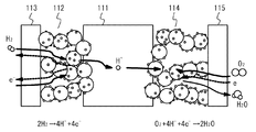
続いて、図1(a)、図1(b)および図2を参照しつつ、通常発電時の燃料電池システム100の動作について説明する。図2は、セル11における発電反応を説明するための模式図である。まず、制御手段51は、燃料ガス流路121に燃料ガスが供給されるように、燃料ガス供給手段20を制御する。この燃料ガスは、ガス拡散層113を透過してアノード触媒層112に到達する。燃料ガスに含まれる水素は、アノード触媒層112の触媒を介してプロトンと電子とに解離する。プロトンは、電解質膜111を伝導してカソード触媒層114に到達する。
Next, the operation of the fuel cell system 100 during normal power generation will be described with reference to FIG. 1 (a), FIG. 1 (b) and FIG. FIG. 2 is a schematic diagram for explaining the power generation reaction in the
また、制御手段51は、酸化剤ガス流路131に酸化剤ガスが供給されるように、酸化剤ガス供給手段30を制御する。この酸化剤ガスは、ガス拡散層115を透過してカソード触媒層114に到達する。カソード触媒層114においては、触媒を介してプロトンと酸素とが反応する。それにより、電力が発生するとともに、水が生成される。生成された水は、酸化剤ガス流路131を通って排出される。
Further, the control means 51 controls the oxidant gas supply means 30 so that the oxidant
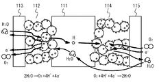
カソード側において酸素が欠乏してくると、カソード触媒層114における水の生成反応が抑制される。この場合、図3に示すように、アノード触媒層112において水素がプロトン化し、カソード触媒層114においてプロトンが水素化する。したがって、水素濃淡電池が形成される。この場合、図2の場合に比較してセル電圧が変動する。
When oxygen is deficient on the cathode side, the water generation reaction in the
アノード側において水素が欠乏してくると、水素のプロトン化が抑制される。この場合、図4に示すように、アノード触媒層112において水の電気分解反応等が生じる。この場合、図2の場合に比較してセル電圧が変動する。これらのセル電圧の変動を検出することによって、酸素欠、水素欠等に起因するセルの異常を検出することができる。
When hydrogen is deficient on the anode side, protonation of hydrogen is suppressed. In this case, as shown in FIG. 4, an electrolysis reaction of water occurs in the
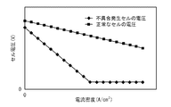
本実施例においては、発電電流密度の増減に対するセル電圧の変化において、変極点が現れるか否かによって、酸素欠、水素欠等に起因するセルの異常を検出する。図5は、電流密度とセル電圧との関係を示す図である。図5において、横軸は電流密度を示し、縦軸はセル電圧を示す。図5に示すように、正常なセルにおいては、電流密度の増加に対してセル電圧が線形に低下する傾向にある。これに対して、水素欠等の不具合が生じているセルにおいては、電流密度の増加に対するセル電圧の低下幅が大きくなるとともに、所定の電流密度以上になった場合にセル電圧の低下幅が小さくなる。 In this embodiment, a cell abnormality caused by oxygen deficiency, hydrogen deficiency, or the like is detected depending on whether or not an inflection point appears in a change in cell voltage with respect to increase or decrease in generated current density. FIG. 5 is a diagram illustrating the relationship between current density and cell voltage. In FIG. 5, the horizontal axis indicates the current density, and the vertical axis indicates the cell voltage. As shown in FIG. 5, in a normal cell, the cell voltage tends to decrease linearly as the current density increases. On the other hand, in a cell in which a problem such as lack of hydrogen occurs, the cell voltage decrease with respect to the increase in current density increases, and when the current density exceeds a predetermined value, the cell voltage decrease decreases. Become.
このように電流密度に対するセル電圧の傾きが変化する点が変極点である。この変極点が検出されれば、セル群のいずれかのセルにおいて酸素欠、水素欠等の不具合が生じていると判定することができる。以下、変極点の検出の詳細について説明する。 The point where the slope of the cell voltage changes with respect to the current density is the inflection point. If this inflection point is detected, it can be determined that a defect such as lack of oxygen or lack of hydrogen has occurred in any cell of the cell group. Hereinafter, details of inflection point detection will be described.
図6(a)および図6(b)は、基準電圧を用いた変極点検出について説明するための図である。図6(a)および図6(b)において、横軸は電流密度を示し、縦軸は各セル群のセル一枚当たりの電圧を示す。図6(a)においては、基準電圧Vstdと測定電圧Vとの差に基づいて、変極点を検出する。 FIGS. 6A and 6B are diagrams for explaining inflection point detection using a reference voltage. 6A and 6B, the horizontal axis indicates the current density, and the vertical axis indicates the voltage per cell in each cell group. In FIG. 6A , the inflection point is detected based on the difference between the reference voltage Vstd and the measured voltage V.
基準電圧Vstdとは、各セル群においてセル電圧が変極しないことを前提として得られた基準電圧のことである。例えば、基準電圧Vstdは、1次回帰によって算出される値である。燃料電池スタック10の起動時等において電流密度が上昇する過程において算出してもよく、あらかじめ測定しておいてもよい。また、電流密度の上限付近および下限付近においてはセル電圧が電流密度に対して線形に変化しないおそれがある。したがって、セル11が出力可能な電流密度範囲の上下の所定量(例えば、5%程度)ずつを除外して1次回帰してもよい。それにより、1次回帰の精度を向上させることができる。
The reference voltage V std is a reference voltage obtained on the assumption that the cell voltage does not change in each cell group. For example, the reference voltage V std is a value calculated by linear regression. It may be calculated in the process of increasing the current density at the time of starting the
基準電圧Vstdの算出の一例について説明する。まず、所定値以下の電流密度範囲において、電流密度の偏差平方和(Σ(Ii−Iave)2)を求める。ここで、Iiは電流密度を示し、Iaveは上記電流密度範囲における平均電流密度を示す。次に、電流密度およびセル一枚あたりの電圧の偏差積和(Σ(Ii−Iave)(Vi−Vave))を求める。ここで、Viはセル一枚あたりの電圧を示し、Vaveは上記電流密度範囲における平均電圧を示す。次に、下記式(1)を用いて回帰係数bを求め、下記式(2)を用いて回帰式切片aを求める。それにより、基準電圧Vstdが下記式(3)のように算出される。
b=(Σ(Ii−Iave)(Vi−Vave))/(Σ(Ii−Iave)2) (1)
a=Vave−b×Iave (2)
Vstd=a+b×I (3)
An example of calculation of the reference voltage V std will be described. First, a deviation sum of squares of current density (Σ (I i −I ave ) 2 ) is obtained in a current density range of a predetermined value or less. Here, I i indicates the current density, and I ave indicates the average current density in the current density range. Next, a sum of deviation products (Σ (I i −I ave ) (V i −V ave )) of current density and voltage per cell is obtained. Here, V i represents a voltage per one cell, V ave represents the average voltage at the current density range. Next, the regression coefficient b is obtained using the following equation (1), and the regression equation intercept a is obtained using the following equation (2). Thereby, the reference voltage V std is calculated as in the following formula (3).
b = (Σ (I i −I ave ) (V i −V ave )) / (Σ (I i −I ave ) 2 ) (1)
a = V ave −b × I ave (2)
V std = a + b × I (3)
図6(a)に示すように、変極点より高電流密度側においては、対象セル群のセル一枚あたりの測定電圧V−基準電圧Vstd>0となる。したがって、測定電圧V−基準電圧Vstdがプラスになった時点を変極点として検出することができる。測定誤差、突発的な環境変化等を回避するために、オフセットを設定してもよい。例えば、図6(b)に示すように、測定電圧V−基準電圧Vstd>0かつ、測定電圧V−基準電圧Vstd>C(Cは所定のオフセット値)となった時点を変極点として検出することができる。 As shown in FIG. 6A, on the higher current density side than the inflection point, measurement voltage V-reference voltage V std > 0 per cell in the target cell group. Therefore, the time point at which the measured voltage V-reference voltage Vstd becomes positive can be detected as an inflection point. An offset may be set to avoid measurement errors, sudden environmental changes, and the like. For example, as shown in FIG. 6B, the time when the measured voltage V−reference voltage V std > 0 and the measured voltage V−reference voltage V std > C (C is a predetermined offset value) is used as an inflection point. Can be detected.
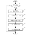
以下、変極点の検出フローについて説明する。図7は、基準電圧Vstdを算出するためのフローチャートの一例を示す図である。図7のフローチャートは、所定の周期で制御手段51によって実行される。図7に示すように、まず、制御手段51は、データの採用が可能であるか否かを判定する(ステップS1)。この場合の判定基準として、後述する図8のフローチャートを用いることができる。 The inflection point detection flow will be described below. FIG. 7 is a diagram illustrating an example of a flowchart for calculating the reference voltage Vstd . The flowchart of FIG. 7 is executed by the control means 51 at a predetermined cycle. As shown in FIG. 7, first, the control means 51 determines whether or not data can be adopted (step S1). As a determination criterion in this case, a flowchart of FIG. 8 described later can be used.
ステップS1においてデータ採用可と判定されなかった場合、制御手段51は、フローチャートの実行を終了する。ステップS1においてデータ採用可と判定された場合、制御手段51は、電圧検出手段41から各セル群の発電電圧を取得するとともに、電流検出手段42から発電電流を取得する(ステップS2)。次に、制御手段51は、発電電流データおよび発電電圧データをステップS2で取得した値に更新する(ステップS3)。
If it is not determined in step S1 that the data can be adopted, the
次いで、制御手段51は、更新されたデータを用いて、セル群ごとに回帰分析(単回帰)を実施する(ステップS4)。次に、制御手段51は、切片aおよび回帰係数bを算出する(ステップS5)。次いで、制御手段51は、切片aおよび回帰係数bをステップS5で算出した値に更新する(ステップS6)。その後、制御手段51は、フローチャートの実行を終了する。このフローチャートの実行によって、セル群ごとに基準電圧Vstdが算出される。 Next, the control means 51 performs a regression analysis (single regression) for each cell group using the updated data (step S4). Next, the control means 51 calculates the intercept a and the regression coefficient b (step S5). Next, the control means 51 updates the intercept a and the regression coefficient b to the values calculated in step S5 (step S6). Thereafter, the control means 51 ends the execution of the flowchart. By executing this flowchart, the reference voltage V std is calculated for each cell group.
図8は、図7のステップS1の判定ルーチンの一例を示す図である。図8のフローチャートは、図7のステップS1の実行によって実行される。まず、制御手段51は、異常回避処置中であるか否かを判定する(ステップS11)。異常回避処置とは、燃料電池スタック10の異常を回避するための所定の処置である。ステップS11において異常回避処置中であると判定された場合、制御手段51は、データ採用不可であると判定する(ステップS12)。その後、制御手段51は、フローチャートの実行を終了する。
FIG. 8 is a diagram showing an example of the determination routine in step S1 of FIG. The flowchart in FIG. 8 is executed by executing step S1 in FIG. First, the control means 51 determines whether or not an abnormality avoidance procedure is being performed (step S11). The abnormality avoidance treatment is a predetermined treatment for avoiding abnormality of the
ステップS11において異常回避処置中であると判定されなかった場合、制御手段51は、燃料電池スタック10の内部を流動する冷却水の温度が規定範囲内にあるか否かを判定する(ステップS13)。ステップS13において冷却水の温度が規定範囲内にあると判定されなかった場合、制御手段51は、データ採用不可であると判定する(ステップS12)。その後、制御手段51は、フローチャートの実行を終了する。
If it is not determined in step S11 that the abnormality avoidance treatment is being performed, the
ステップS13において冷却水の温度が規定範囲内にあると判定された場合、制御手段51は、セル電圧または発電電流の加減速が過度の加減速でないか否かを判定する(ステップS14)。ステップS14において過度の加減速が生じていないと判定されなかった場合、制御手段51は、データ採用不可であると判定する(ステップS12)。その後、制御手段51は、フローチャートの実行を終了する。
When it is determined in step S13 that the temperature of the cooling water is within the specified range, the
ステップS14において過度の加減速が生じていないと判定された場合、制御手段51は、反応ガスの圧力が規定値以上であるか否かを判定する(ステップS15)。ステップS15において反応ガスの圧力が規定値以上であると判定されなかった場合、制御手段51は、データ採用不可であると判定する(ステップS12)。ステップS15において反応ガスの圧力が規定値以上であると判定された場合、制御手段51は、データ採用可であると判定する(ステップS16)。その後、制御手段51は、フローチャートの実行を終了する。
When it is determined in step S14 that excessive acceleration / deceleration has not occurred, the control means 51 determines whether or not the pressure of the reaction gas is equal to or higher than a specified value (step S15). When it is not determined in step S15 that the pressure of the reaction gas is equal to or higher than the specified value, the
図9は、変極点を検出するためのフローチャートの一例を示す図である。図9のフローチャートは、所定の周期で判定手段52によって実行される。具体的には、図9のフローチャートは、例えば、所定時間経過した場合、電流密度が所定量変化した場合等に実行される。図9に示すように、まず、判定手段52は、同一電流密度条件下において対象となるセル群の測定電圧V−基準電圧Vstd>0であるか否かを判定する(ステップS21)。ステップS21において測定電圧V−基準電圧Vstd>0であると判定されなかった場合、判定手段52は、フローチャートの実行を終了する。
FIG. 9 is a diagram illustrating an example of a flowchart for detecting an inflection point. The flowchart of FIG. 9 is executed by the
ステップS21において測定電圧V−基準電圧Vstd>0であると判定された場合、判定手段52は、測定電圧V−基準電圧Vstd>オフセット値Cであるか否かを判定する(ステップS23)。ステップS23において測定電圧V−基準電圧Vstd>オフセット値Cであると判定されなかった場合、判定手段52は、フローチャートの実行を終了する。ステップS23において測定電圧V−基準電圧Vstd>オフセット値Cであると判定された場合、判定手段52は、対象セル群に異常が生じていると判断する(ステップS13)。その後、判定手段52は、フローチャートの実行を終了する。
When it is determined in step S21 that the measurement voltage V−the reference voltage V std > 0, the
図9のフローチャートによれば、対象としているセル群の変極点を検出することができる。それにより、対象としているセル群のいずれかのセルに異常が生じているか否かを高い精度で判断することができる。この場合、運転条件の切替等による燃料電池スタック10の発電性能低下を抑制することができる。また、対象としているセル群の部品交換等によって燃料電池スタック10の発電性能低下を抑制することができる。さらに、セル群に複数のセルが含まれていても変極点の検出が可能であることから、セルごとに電圧検出手段を設ける必要がない。その結果、コストの低減化を図ることができる。
According to the flowchart of FIG. 9, the inflection point of the target cell group can be detected. As a result, it is possible to determine with high accuracy whether or not an abnormality has occurred in any cell of the target cell group. In this case, it is possible to suppress a decrease in power generation performance of the
なお、上記実施例においては、測定電圧V−基準電圧Vstd>0、または、測定電圧V−基準電圧Vstd>0かつ測定電圧V−基準電圧Vstd>Cとなった場合に、セル群の変極点を検出したが、それに限られない。例えば、測定電圧Vの基準電圧Vstdからの分散が所定値以上になった場合に、セル群に変極点が生じていると検出してもよい。 In the above embodiment, when the measurement voltage V−reference voltage V std > 0 or the measurement voltage V−reference voltage V std > 0 and the measurement voltage V−reference voltage V std > C, the cell group Although the inflection point is detected, it is not limited to this. For example, when the dispersion of the measurement voltage V from the reference voltage Vstd becomes a predetermined value or more, it may be detected that an inflection point is generated in the cell group.
(変形例1)
なお、基準となるセル群のセル電圧を基準電圧とし、この基準電圧との関係を用いて変極点を検出してもよい。図10は、基準電圧との関係を用いた変極点の検出について説明するための図である。図10において、横軸は電流密度を示し、縦軸はセル電圧を示す。
(Modification 1)
Note that an inflection point may be detected using a cell voltage of a reference cell group as a reference voltage and using a relationship with the reference voltage. FIG. 10 is a diagram for explaining detection of an inflection point using a relationship with a reference voltage. In FIG. 10, the horizontal axis indicates the current density, and the vertical axis indicates the cell voltage.
基準電圧として、発電性能が比較的高いセル群のセル電圧を用いることが好ましい。例えば、基準電圧として、セル電圧が最大のセル群の値を用いてもよく、各セル群の平均以上のセル電圧を生じるセル群の値を用いてもよい。また、基準電圧として、他のセル群よりもセル枚数の少ないセル群の値を用いてもよい。さらに、耐久性の高いセル群の値を用いてもよい。ここで、耐久性の高いセル群とは、劣化しにくいセル群のことをいう。例えば、結晶性の高いカーボンを含む触媒層を備えるセル群、粒径の大きい白金を担持する触媒層を備えるセル群等を耐久性の高いセル群として用いることができる。また、あらかじめ測定しておいたセル群のセル電圧を用いてもよい。なお、セル11が出力可能な電流密度範囲の上下の所定量(例えば、5%程度)ずつを除外して基準電圧としてもよい。本変形例においては、一例として、基準電圧として最大のセル電圧を示すセル群のセル電圧Vmaxを用いる。また、最小のセル電圧Vminを示すセル群を対象セル群とする。
As the reference voltage, it is preferable to use a cell voltage of a cell group having relatively high power generation performance. For example, the value of the cell group having the maximum cell voltage may be used as the reference voltage, or the value of the cell group that generates a cell voltage that is equal to or higher than the average of each cell group may be used. Further, as the reference voltage, a value of a cell group having a smaller number of cells than other cell groups may be used. Further, a value of a highly durable cell group may be used. Here, the highly durable cell group refers to a cell group that is not easily deteriorated. For example, a cell group including a catalyst layer containing carbon having high crystallinity, a cell group including a catalyst layer supporting platinum having a large particle diameter, and the like can be used as the highly durable cell group. Moreover, you may use the cell voltage of the cell group measured beforehand. Note that the reference voltage may be excluded by excluding predetermined amounts (for example, about 5%) above and below the current density range that the
図10に示すように、基準電圧として用いるセル電圧Vmaxは、電流密度の増加とともにほぼ線形に低下する。また、反応ガスが正常な範囲でばらついているセル群は、基準電圧に近い電圧を示す。これに比較して、反応ガス欠等が生じているセル群においては、基準電圧に比較してセル電圧が低下するとともに、変極点が現れる。 As shown in FIG. 10, the cell voltage V max used as the reference voltage decreases almost linearly as the current density increases. A cell group in which the reaction gas varies in a normal range shows a voltage close to the reference voltage. In comparison with this, in the cell group in which the reaction gas shortage or the like occurs, the cell voltage is lowered compared to the reference voltage, and an inflection point appears.
本変形例においては、変極点を検出するために、基準電圧の電流密度に対する傾きを用いる。変極点よりも低電流密度側においては、dVmin/dI−dVmax/dI<0となる。これに対して、変極点よりも高電流密度側においては、dVmin/dI−dVmax/dI>0となる。したがって、dVmin/dI−dVmax/dIがマイナスからプラスに変化するか否かを判定することによって、変極点が存在するか否かを判定することができる。測定誤差等を考慮すると、dVmin/dI−dVmax/dI>E(オフセット値)になった場合に、変極点が存在すると判定してもよい。 In this modification, in order to detect an inflection point, a gradient of the reference voltage with respect to the current density is used. On the lower current density side than the inflection point, dV min / dI−dV max / dI <0. On the other hand, dV min / dI−dV max / dI> 0 on the higher current density side than the inflection point. Therefore, whether or not an inflection point exists can be determined by determining whether or not dV min / dI−dV max / dI changes from minus to plus. In consideration of measurement errors and the like, it may be determined that an inflection point exists when dV min / dI−dV max / dI> E (offset value).
図11は、変極点を検出するするためのフローチャートの一例を示す図である。図11のフローチャートは、所定の周期で判定手段52によって実行される。具体的には、図11のフローチャートは、例えば、所定時間経過した場合、電流密度が所定量変化した場合等に実行される。図11に示すように、判定手段52は、同一の電流密度条件下においてVmax−Vmin>Dであるか否かを判定する(ステップS31)。このようにVmaxとVminとの差に所定のしきい値を設けることによって、変極点が存在するセル群をより正確に検出することができる。ステップS31においてVmax−Vmin>Dであると判定されなかった場合、判定手段52は、フローチャートの実行を終了する。
FIG. 11 is a diagram illustrating an example of a flowchart for detecting an inflection point. The flowchart of FIG. 11 is executed by the
ステップS31においてVmax−Vmin>Dであると判定された場合、判定手段52は、dVmin/dI−dVmax/dI>オフセット値Eであるか否かを判定する(ステップS32)。このようにオフセット値を設けることによって、測定誤差等による誤判断を回避することができる。ステップS32においてdVmin/dI−dVmax/dI>オフセット値Eであると判定されなかった場合、判定手段52は、フローチャートの実行を終了する。ステップS32においてdVmin/dI−dVmax/dI>オフセット値Eであると判定された場合、判定手段52は、対象セル群に異常が生じていると判断する(ステップS33)。その後、判定手段52は、フローチャートの実行を終了する。
When it is determined in step S31 that V max −V min > D, the
図11のフローチャートによれば、対象としているセル群の変極点を検出することができる。それにより、対象としているセル群のいずれかのセルに異常が生じているか否かを高い精度で判断することができる。さらに、セル群に複数のセルが含まれていても変極点の検出が可能であることから、セルごとに電圧検出手段を設ける必要がない。その結果、コストの低減化を図ることができる。 According to the flowchart of FIG. 11, the inflection point of the target cell group can be detected. As a result, it is possible to determine with high accuracy whether or not an abnormality has occurred in any cell of the target cell group. Furthermore, since the inflection point can be detected even if a plurality of cells are included in the cell group, it is not necessary to provide a voltage detection means for each cell. As a result, cost can be reduced.
(変形例2)
ここで、各セル群に含まれるセル11の枚数が多くなればなるほど、変極点の検出が困難になる。図12は、一例として各セル群に10枚のセル11が含まれる場合を示す。図12において、横軸は電流密度を示し、縦軸は各セル群のセル電圧を各セル群に含まれるセル枚数で割った値を示す。図12に示すように、基準となるセル群の基準電圧と不具合が生じているセル群のセル電圧との差が小さくなってしまう。したがって、変極点の検出が困難になる。
(Modification 2)
Here, as the number of
そこで、本変形例において、対象とするセル群の発電電圧の基準電圧からの乖離率を用いて変極点を検出する。ここで、乖離率は、下記式(4)のように定義することができる。なお、下記式(4)においては、同一電流密度条件下での電圧値を用いている。
乖離率=(基準電圧−対象セル群の発電電圧)/基準電圧×100% (4)
Therefore, in this modification, the inflection point is detected using the deviation rate from the reference voltage of the generated voltage of the target cell group. Here, the deviation rate can be defined as shown in the following formula (4). In the following formula (4), the voltage value under the same current density condition is used.
Deviation rate = (reference voltage−generated voltage of target cell group) / reference voltage × 100% (4)
図13は、電流密度と乖離率との関係を示す図である。図13において、横軸は電流密度を示し、縦軸は乖離率を示す。図13に示すように、反応ガスが正常な範囲内でばらつく場合には、電流密度の増加とともに乖離率も増加する。これに比較して、反応ガス欠等が生じているセル群においては、電流密度の増加とともに乖離率も増加し、所定の値を境に乖離率が低下し始める。この値が変極点として検出される。 FIG. 13 is a diagram showing the relationship between the current density and the deviation rate. In FIG. 13, the horizontal axis indicates the current density, and the vertical axis indicates the deviation rate. As shown in FIG. 13, when the reaction gas varies within a normal range, the deviation rate increases as the current density increases. Compared to this, in the cell group in which the reaction gas shortage or the like occurs, the divergence rate increases as the current density increases, and the divergence rate starts to decrease at a predetermined value. This value is detected as an inflection point.
図14(a)、図14(b)および図15は、変極点を検出するするためのフローチャートの一例を示す図である。図14(a)、図14(b)および図15のフローチャートは、所定の周期で判定手段52によって実行される。具体的には、図14(a)、図14(b)および図15のフローチャートは、例えば、所定時間経過した場合、電流密度が所定量変化した場合等に実行される。図14(a)に示すように、判定手段52は、図9のステップS21と同様に、同一電流密度条件下において測定電圧V−基準電圧Vstd>0であるか否かを判定する(ステップS41)。ステップS41において測定電圧V−基準電圧Vstd>0であると判定されなかった場合、判定手段52は、フローチャートの実行を終了する。
FIG. 14A, FIG. 14B, and FIG. 15 are diagrams illustrating an example of a flowchart for detecting an inflection point. The flowcharts of FIGS. 14A, 14B, and 15 are executed by the
ステップS41において測定電圧V−基準電圧Vstd>0であると判定された場合、判定手段52は、電流密度の増加に対する乖離率(d(Vmax−V)/dI)が負の傾きを持つか否かを判定する(ステップS42)。ステップS42において乖離率が負の傾きを持つと判定されなかった場合、判定手段52は、フローチャートの実行を終了する。ステップS42において乖離率が負の傾きを持つと判定された場合、判定手段52は、対象セル群のいずれかのセル11に異常が生じていると判断する(ステップS43)。その後、判定手段52は、フローチャートの実行を終了する。
When it is determined in step S41 that the measured voltage V−the reference voltage V std > 0, the
また、図14(b)に示すように、判定手段52は、図14(a)のステップS41の代わりに、図11のステップS31と同様にVmax−V>Dであるか否かを判定してもよい(ステップS51)。
Further, as shown in FIG. 14B, the
また、図15に示すように、判定手段52は、図14(a)のステップS42の代わりに、ステップS62を実行してもよい。ステップS62においては、判定手段52は、対象セル群の低電流密度域における乖離率の電流密度に対する傾きbLowと高電流密度域における乖離率の電流密度に対する傾きbHighとの積が負になるか否かを判定する。この場合、変極点が生じる場合には、傾きbLowおよび傾きbHighのいずれか一方が正の値になり、いずれか他方が負の値になる。したがって、変極点が生じる場合には、bLow×bHigh<0となる。なお、上記の低電流密度域および高電流密度域は、必要に応じて再設定することができる。
Further, as shown in FIG. 15, the
図14(a)、図14(b)および図15のフローチャートによれば、対象としているセル群の乖離率を用いて変極点を検出することができる。それにより、対象としているセル群に異常が生じているか否かをより高い精度で判断することができる。さらに、セル群に複数のセルが含まれていても変極点の検出が可能であることから、セルごとに電圧検出手段を設ける必要がない。その結果、コストの低減化を図ることができる。 According to the flowcharts of FIGS. 14A, 14B, and 15, the inflection point can be detected using the deviation rate of the target cell group. Thereby, it can be judged with higher precision whether abnormality has arisen in the cell group made into object. Furthermore, since the inflection point can be detected even if a plurality of cells are included in the cell group, it is not necessary to provide a voltage detection means for each cell. As a result, cost can be reduced.
(変形例3)
対象とするセル群の乖離率の1次回帰直線の切片に基づいて、変極点が生じているか否かを判定してもよい。図13において説明したように、変極点が生じると、電流密度に対する乖離率の傾きが正から負に変わる。したがって、変極点が生じると、図16に示すように、乖離率の1次回帰直線の切片が大きくなる。この切片が所定値以上になった場合に、変極点が生じていると判断することができる。
(Modification 3)
Whether or not an inflection point has occurred may be determined based on the intercept of the primary regression line of the deviation rate of the target cell group. As described with reference to FIG. 13, when an inflection point occurs, the slope of the deviation rate with respect to the current density changes from positive to negative. Therefore, when an inflection point occurs, as shown in FIG. 16, the intercept of the linear regression line of the deviation rate becomes large. When this intercept exceeds a predetermined value, it can be determined that an inflection point has occurred.
図17は、変極点を検出するためのフローチャートの一例を示す図である。図17のフローチャートは、所定の周期で判定手段52によって実行される。具体的には、図17のフローチャートは、例えば、所定時間経過した場合、電流密度が所定量変化した場合等に実行される。図17に示すように、まず、判定手段52は、図9のステップS21と同様に、測定電圧V−基準電圧Vstd>0であるか否かを判定する(ステップS71)。ステップS71において測定電圧V−基準電圧Vstd>0であると判定されなかった場合、判定手段52は、フローチャートの実行を終了する。
FIG. 17 is a diagram illustrating an example of a flowchart for detecting an inflection point. The flowchart of FIG. 17 is executed by the
ステップS71において測定電圧V−基準電圧Vstd>0であると判定された場合、判定手段52は、対象セル群の乖離率の一次回帰式の切片aminがしきい値Eを上回ったか否かを判定する(ステップS72)。ステップS72において切片aminがしきい値Eを上回ったと判定されなかった場合、判定手段52は、フローチャートの実行を終了する。ステップS72において切片aminがしきい値Eを上回ったと判定された場合、判定手段52は、対象セル群のいずれかのセル11に異常が生じていると判断する(ステップS73)。その後、判定手段52は、フローチャートの実行を終了する。
When it is determined in step S71 that the measured voltage V−the reference voltage V std > 0, the
図17のフローチャートによれば、対象としているセル群の乖離率を用いて変極点を検出することができる。それにより、対象としているセル群に異常が生じているか否かをより高い精度で判断することができる。さらに、セル群に複数のセルが含まれていても変極点の検出が可能であることから、セルごとに電圧検出手段を設ける必要がない。その結果、コストの低減化を図ることができる。 According to the flowchart of FIG. 17, the inflection point can be detected using the deviation rate of the target cell group. Thereby, it can be judged with higher precision whether abnormality has arisen in the cell group made into object. Furthermore, since the inflection point can be detected even if a plurality of cells are included in the cell group, it is not necessary to provide a voltage detection means for each cell. As a result, cost can be reduced.
10 燃料電池スタック
11 セル
20 燃料ガス供給手段
30 酸化剤ガス供給手段
41 電圧検出手段
42 電流検出手段
50 処理部
51 制御手段
52 判定手段
100 燃料電池システム
DESCRIPTION OF
Claims (18)
前記セル群の発電電流密度を検出する電流密度検出手段と、
前記電圧検出手段および前記電流密度検出手段の検出結果に基づいて、前記発電電流密度に対する前記セル電圧の変化の変極点が存在するか否かを判定する判定手段と、を備えることを特徴とする燃料電池システム。 Voltage detecting means for detecting a cell voltage of a cell group including one or more cells;
Current density detection means for detecting the generated current density of the cell group;
Determination means for determining whether or not there is an inflection point of the change in the cell voltage with respect to the generated current density based on detection results of the voltage detection means and the current density detection means. Fuel cell system.
前記セル群の発電電流密度を検出する電流密度検出ステップと、
前記電圧検出ステップおよび前記電流密度検出ステップにおける検出結果に基づいて、前記発電電流密度に対する前記セル電圧の変化の変極点が存在するか否かを判定する判定ステップと、を含むことを特徴とする燃料電池の状態検知方法。 A voltage detection step of detecting a cell voltage of a cell group including one or more cells;
A current density detection step for detecting a generated current density of the cell group;
And a determination step of determining whether or not there is an inflection point of a change in the cell voltage with respect to the generated current density based on detection results in the voltage detection step and the current density detection step. A method for detecting the state of a fuel cell.
Priority Applications (6)
| Application Number | Priority Date | Filing Date | Title |
|---|---|---|---|
| JP2008212250A JP5326423B2 (en) | 2008-08-20 | 2008-08-20 | FUEL CELL SYSTEM AND FUEL CELL STATE DETECTION METHOD |
| US13/059,752 US9337504B2 (en) | 2008-08-20 | 2009-08-19 | Fuel cell system and fuel cell status detection method |
| CA2733768A CA2733768C (en) | 2008-08-20 | 2009-08-19 | Fuel cell system and fuel cell status detection method |
| DE112009002043.7T DE112009002043B4 (en) | 2008-08-20 | 2009-08-19 | Fuel cell system and fuel cell condition detection method |
| PCT/IB2009/006584 WO2010020861A1 (en) | 2008-08-20 | 2009-08-19 | Fuel cell system and fuel cell status detection method |
| CN200980132419.XA CN102124597B (en) | 2008-08-20 | 2009-08-19 | Fuel cell system and fuel cell status detection method |
Applications Claiming Priority (1)
| Application Number | Priority Date | Filing Date | Title |
|---|---|---|---|
| JP2008212250A JP5326423B2 (en) | 2008-08-20 | 2008-08-20 | FUEL CELL SYSTEM AND FUEL CELL STATE DETECTION METHOD |
Publications (2)
| Publication Number | Publication Date |
|---|---|
| JP2010049894A true JP2010049894A (en) | 2010-03-04 |
| JP5326423B2 JP5326423B2 (en) | 2013-10-30 |
Family
ID=41212191
Family Applications (1)
| Application Number | Title | Priority Date | Filing Date |
|---|---|---|---|
| JP2008212250A Expired - Fee Related JP5326423B2 (en) | 2008-08-20 | 2008-08-20 | FUEL CELL SYSTEM AND FUEL CELL STATE DETECTION METHOD |
Country Status (6)
| Country | Link |
|---|---|
| US (1) | US9337504B2 (en) |
| JP (1) | JP5326423B2 (en) |
| CN (1) | CN102124597B (en) |
| CA (1) | CA2733768C (en) |
| DE (1) | DE112009002043B4 (en) |
| WO (1) | WO2010020861A1 (en) |
Cited By (4)
| Publication number | Priority date | Publication date | Assignee | Title |
|---|---|---|---|---|
| WO2011136111A1 (en) | 2010-04-28 | 2011-11-03 | 矢崎総業株式会社 | Voltage detection device for fuel cell |
| JP2011249171A (en) * | 2010-05-27 | 2011-12-08 | Toyota Motor Corp | Fuel battery system, method of controlling fuel battery system, and method of determining deterioration of fuel battery stack |
| JP2014216095A (en) * | 2013-04-23 | 2014-11-17 | 本田技研工業株式会社 | Abnormality detection method of fuel cell stack |
| JP2016095907A (en) * | 2014-11-12 | 2016-05-26 | トヨタ自動車株式会社 | Power generation monitor, fuel battery system and power generation monitoring method |
Families Citing this family (7)
| Publication number | Priority date | Publication date | Assignee | Title |
|---|---|---|---|---|
| JP5287815B2 (en) * | 2010-09-28 | 2013-09-11 | トヨタ自動車株式会社 | Fuel cell system, negative voltage factor identification method and program |
| WO2016151695A1 (en) * | 2015-03-20 | 2016-09-29 | 三菱自動車工業株式会社 | Vehicle power control device |
| KR101684118B1 (en) | 2015-05-27 | 2016-12-07 | 현대자동차주식회사 | Fuel cell purging method |
| KR101724500B1 (en) * | 2015-10-28 | 2017-04-07 | 현대자동차 주식회사 | Fuel cell stack diagnostic system and diagnostic method thereof |
| CN111610805B (en) * | 2020-06-01 | 2023-10-10 | 宁波弘讯科技股份有限公司 | Pressure control method, system and device of press-fitting machine |
| JP7211400B2 (en) * | 2020-06-26 | 2023-01-24 | トヨタ自動車株式会社 | fuel cell system |
| DE102021209031A1 (en) | 2021-08-18 | 2023-02-23 | Robert Bosch Gesellschaft mit beschränkter Haftung | Method of monitoring an electrochemical cell unit |
Citations (2)
| Publication number | Priority date | Publication date | Assignee | Title |
|---|---|---|---|---|
| JPH02273467A (en) * | 1989-04-12 | 1990-11-07 | Fuji Electric Co Ltd | Starting method for fuel cell |
| JP2007080708A (en) * | 2005-09-15 | 2007-03-29 | Furukawa Battery Co Ltd:The | Deterioration diagnostic method of battery power source |
Family Cites Families (21)
| Publication number | Priority date | Publication date | Assignee | Title |
|---|---|---|---|---|
| US4424491A (en) * | 1981-05-20 | 1984-01-03 | The United States Of America As Represented By The United States Department Of Energy | Automatic voltage imbalance detector |
| US4904548A (en) * | 1987-08-03 | 1990-02-27 | Fuji Electric Co., Ltd. | Method for controlling a fuel cell |
| CA2018639A1 (en) * | 1990-06-08 | 1991-12-08 | James D. Blair | Method and apparatus for comparing fuel cell voltage |
| US5763113A (en) * | 1996-08-26 | 1998-06-09 | General Motors Corporation | PEM fuel cell monitoring system |
| US5945229A (en) * | 1997-02-28 | 1999-08-31 | General Motors Corporation | Pattern recognition monitoring of PEM fuel cell |
| WO2000002282A1 (en) | 1998-07-02 | 2000-01-13 | Ballard Power Systems Inc. | Sensor cell for an electrochemical fuel cell stack |
| JP3395694B2 (en) * | 1999-03-09 | 2003-04-14 | 日産自動車株式会社 | Calculation method for battery capacity deterioration of secondary battery |
| US6455180B1 (en) | 1999-07-02 | 2002-09-24 | General Motors Corporation | Flexible method for monitoring fuel cell voltage |
| DE29912681U1 (en) | 1999-07-15 | 1999-10-07 | Heliocentris Energiesysteme | Experiment set for fuel cell technology |
| CA2389740A1 (en) * | 1999-08-23 | 2001-03-01 | Ballard Power Systems Inc. | Supported catalysts for the anode of a voltage reversal tolerant fuel cell |
| US6893757B2 (en) * | 2001-01-26 | 2005-05-17 | Kabushikikaisha Equos Research | Fuel cell apparatus and method of controlling fuel cell apparatus |
| JP2002358993A (en) | 2001-05-31 | 2002-12-13 | Mitsubishi Electric Corp | Laminated fuel cell and measuring method of cell voltage |
| KR100438549B1 (en) | 2001-11-09 | 2004-07-03 | 엘지전자 주식회사 | Lcd apparatus for mobile phone |
| JP4214761B2 (en) * | 2002-01-31 | 2009-01-28 | 株式会社デンソー | Fuel cell system |
| JP4354253B2 (en) * | 2003-10-31 | 2009-10-28 | エスペック株式会社 | Fuel cell evaluation method and fuel cell evaluation apparatus |
| JP2005142062A (en) | 2003-11-07 | 2005-06-02 | Matsushita Electric Ind Co Ltd | Inspection device and inspection method of fuel cell |
| JP2006155965A (en) | 2004-11-25 | 2006-06-15 | Kri Inc | Method for evaluating fuel cell, test apparatus for evaluating fuel cell, and analysis program for evaluating fuel cell |
| JP5055696B2 (en) | 2004-12-22 | 2012-10-24 | 日産自動車株式会社 | Fuel cell system |
| JP4734963B2 (en) * | 2005-03-01 | 2011-07-27 | 株式会社デンソー | Fuel cell system |
| CN100363738C (en) * | 2005-12-09 | 2008-01-23 | 清华大学 | Water deficiency diagnosis method of fuel battery proton exchange membrane and monitoring system |
| DE102009026917B4 (en) | 2009-06-12 | 2024-03-07 | Robert Bosch Gmbh | Detection of water accumulation on the cathode side and initiation of appropriate countermeasures |
-
2008
- 2008-08-20 JP JP2008212250A patent/JP5326423B2/en not_active Expired - Fee Related
-
2009
- 2009-08-19 US US13/059,752 patent/US9337504B2/en active Active
- 2009-08-19 CA CA2733768A patent/CA2733768C/en active Active
- 2009-08-19 WO PCT/IB2009/006584 patent/WO2010020861A1/en active Application Filing
- 2009-08-19 DE DE112009002043.7T patent/DE112009002043B4/en active Active
- 2009-08-19 CN CN200980132419.XA patent/CN102124597B/en not_active Expired - Fee Related
Patent Citations (2)
| Publication number | Priority date | Publication date | Assignee | Title |
|---|---|---|---|---|
| JPH02273467A (en) * | 1989-04-12 | 1990-11-07 | Fuji Electric Co Ltd | Starting method for fuel cell |
| JP2007080708A (en) * | 2005-09-15 | 2007-03-29 | Furukawa Battery Co Ltd:The | Deterioration diagnostic method of battery power source |
Cited By (5)
| Publication number | Priority date | Publication date | Assignee | Title |
|---|---|---|---|---|
| WO2011136111A1 (en) | 2010-04-28 | 2011-11-03 | 矢崎総業株式会社 | Voltage detection device for fuel cell |
| US9935324B2 (en) | 2010-04-28 | 2018-04-03 | Yazaki Corporation | Voltage detection device for fuel cell |
| JP2011249171A (en) * | 2010-05-27 | 2011-12-08 | Toyota Motor Corp | Fuel battery system, method of controlling fuel battery system, and method of determining deterioration of fuel battery stack |
| JP2014216095A (en) * | 2013-04-23 | 2014-11-17 | 本田技研工業株式会社 | Abnormality detection method of fuel cell stack |
| JP2016095907A (en) * | 2014-11-12 | 2016-05-26 | トヨタ自動車株式会社 | Power generation monitor, fuel battery system and power generation monitoring method |
Also Published As
| Publication number | Publication date |
|---|---|
| CN102124597B (en) | 2014-02-26 |
| CA2733768A1 (en) | 2010-02-25 |
| US9337504B2 (en) | 2016-05-10 |
| CN102124597A (en) | 2011-07-13 |
| JP5326423B2 (en) | 2013-10-30 |
| DE112009002043T5 (en) | 2011-06-22 |
| CA2733768C (en) | 2013-05-28 |
| DE112009002043B4 (en) | 2022-11-17 |
| WO2010020861A1 (en) | 2010-02-25 |
| US20110151347A1 (en) | 2011-06-23 |
Similar Documents
| Publication | Publication Date | Title |
|---|---|---|
| JP5326423B2 (en) | FUEL CELL SYSTEM AND FUEL CELL STATE DETECTION METHOD | |
| JP5343509B2 (en) | FUEL CELL SYSTEM AND FUEL CELL STATE DETECTION METHOD | |
| JP5330753B2 (en) | Fuel cell system | |
| JP5936976B2 (en) | Operation method of fuel cell | |
| US8241800B2 (en) | Fuel cell system and fuel cell control method | |
| US20130189596A1 (en) | Fuel cell system, method and program of determining cause of negative voltage, and storage medium storing program | |
| KR102096268B1 (en) | Fuel cell system and controlling method thereof | |
| CN101957434B (en) | Method to improve reliability of a fuel cell system using low performance cell detection at low power operation | |
| CN102347499A (en) | Diagnosis and remediation of low anode hydrogen partial pressure in pem fuel cell system | |
| US10020525B2 (en) | Method and system for diagnosing state of fuel cell stack | |
| JP6569464B2 (en) | Fuel cell diagnostic device | |
| JP2009170229A (en) | Manufacturing method of fuel cell, fuel cell system, and the fuel cell | |
| JP2014209416A (en) | Fuel cell system and method for controlling fuel cell system | |
| JP2006278246A (en) | Control method of fuel cell stack | |
| US20070141406A1 (en) | Technique and apparatus to detect carbon monoxide poisoning of a fuel cell stack | |
| KR101349022B1 (en) | Catalyst deterioration jundging method for fuel cell | |
| US20090208781A1 (en) | Method for operating a fuel cell system | |
| US20130004872A1 (en) | Method for early detection of membrane failures of fuel cell stacks and fuel cell system component defects | |
| JP2007035493A (en) | Voltage regulation device for fuel cell | |
| JP5508633B2 (en) | Fuel cell abnormality detection device, fuel cell device, and fuel cell abnormality detection method | |
| JP2010135174A (en) | Fuel cell system and operation method of fuel cell | |
| US10897053B2 (en) | Aging device for fuel cell stack | |
| JP2008177003A (en) | Fuel cell system | |
| JP2022044327A (en) | Fuel cell system | |
| KR20210062192A (en) | A highly durable fuel cell system capable of releasing cell voltage reversal |
Legal Events
| Date | Code | Title | Description |
|---|---|---|---|
| A621 | Written request for application examination |
Free format text: JAPANESE INTERMEDIATE CODE: A621 Effective date: 20101214 |
|
| A977 | Report on retrieval |
Free format text: JAPANESE INTERMEDIATE CODE: A971007 Effective date: 20121108 |
|
| A131 | Notification of reasons for refusal |
Free format text: JAPANESE INTERMEDIATE CODE: A131 Effective date: 20121113 |
|
| A521 | Request for written amendment filed |
Free format text: JAPANESE INTERMEDIATE CODE: A523 Effective date: 20130108 |
|
| TRDD | Decision of grant or rejection written | ||
| A01 | Written decision to grant a patent or to grant a registration (utility model) |
Free format text: JAPANESE INTERMEDIATE CODE: A01 Effective date: 20130625 |
|
| A61 | First payment of annual fees (during grant procedure) |
Free format text: JAPANESE INTERMEDIATE CODE: A61 Effective date: 20130708 |
|
| R151 | Written notification of patent or utility model registration |
Ref document number: 5326423 Country of ref document: JP Free format text: JAPANESE INTERMEDIATE CODE: R151 |
|
| LAPS | Cancellation because of no payment of annual fees |