JP2010049527A - Coin delivery device and coin handling apparatus - Google Patents

Coin delivery device and coin handling apparatus Download PDF

Info

Publication number
JP2010049527A
JP2010049527A JP2008213788A JP2008213788A JP2010049527A JP 2010049527 A JP2010049527 A JP 2010049527A JP 2008213788 A JP2008213788 A JP 2008213788A JP 2008213788 A JP2008213788 A JP 2008213788A JP 2010049527 A JP2010049527 A JP 2010049527A
Authority
JP
Japan
Prior art keywords
coin
coins
carrying disk
state
unit
Prior art date
Legal status (The legal status is an assumption and is not a legal conclusion. Google has not performed a legal analysis and makes no representation as to the accuracy of the status listed.)
Granted
Application number
JP2008213788A
Other languages
Japanese (ja)
Other versions
JP5258452B2 (en
Inventor
Katsuyuki Mobara
勝之 茂原
Takenori Tsuchiya
武徳 土屋
Current Assignee (The listed assignees may be inaccurate. Google has not performed a legal analysis and makes no representation or warranty as to the accuracy of the list.)
Takamisawa Cybernetics Co Ltd
Original Assignee
Takamisawa Cybernetics Co Ltd
Priority date (The priority date is an assumption and is not a legal conclusion. Google has not performed a legal analysis and makes no representation as to the accuracy of the date listed.)
Filing date
Publication date
Application filed by Takamisawa Cybernetics Co Ltd filed Critical Takamisawa Cybernetics Co Ltd
Priority to JP2008213788A priority Critical patent/JP5258452B2/en
Publication of JP2010049527A publication Critical patent/JP2010049527A/en
Application granted granted Critical
Publication of JP5258452B2 publication Critical patent/JP5258452B2/en
Active legal-status Critical Current
Anticipated expiration legal-status Critical

Links

Images

Abstract

<P>PROBLEM TO BE SOLVED: To provide a coin delivery device using a carrying disk that reduces failures such as locking and jamming and can easily resolve such failures if any, even when handling many different denominations. <P>SOLUTION: A carrying disk type coin delivery device guides coins to through-holes in the carrying disk rotated along a sliding surface at the bottom of a coin supply chamber and moves the coins along the sliding surface to deliver out one by one. The carrying disk is provided with a plurality of protrusions on an upper surface except for the center of rotation. At least one of the protrusions has a different distance from the center of rotation from the others, and at least one of the protrusions has a different shape, height or thickness from the others. <P>COPYRIGHT: (C)2010,JPO&INPIT

Description

本発明は、収納した硬貨を一枚ずつ外部に放出する硬貨放出装置および該硬貨放出装置を用いた硬貨処理装置に関する。特に、複数の金種の硬貨を短時間に大量に処理可能な硬貨放出装置及び硬貨処理装置に関する。   The present invention relates to a coin discharging device that discharges stored coins one by one to the outside, and a coin processing device using the coin discharging device. In particular, the present invention relates to a coin discharging device and a coin processing device capable of processing a large amount of coins of a plurality of denominations in a short time.

硬貨処理装置は、例えば、駅の自動券売機に使用されるもので、硬貨入金口から入金された硬貨の合計額を算出して表示し、購入した券等の額を入金額から差し引いたつり銭を払い出し、精算した金額の硬貨を払い出したりする装置である。このつり銭等に充当するための硬貨は、入金された硬貨を金種毎に分別して貯留しておき、再び使用する循環方式が用いられる(例えば、文献1)。しかし、循環方式を用いてもつり銭が不足することがあり、このような場合に備えて予めつり銭を補充・収納する必要がある(例えば、文献2)。   The coin processing device is used for, for example, an automatic ticket vending machine at a station. The coin processing device calculates and displays the total amount of coins deposited from the coin deposit slot, and changes the amount obtained by subtracting the amount of purchased tickets from the deposit amount. This is a device that pays out coins and pays out coins of the adjusted amount. For the coins to be used for the change or the like, a circulating system is used in which the received coins are sorted and stored for each denomination (for example, Document 1). However, there are cases where the change is insufficient using the circulation method, and it is necessary to replenish and store the change in advance in preparation for such a case (for example, Document 2).

つり銭の補充に当たっては、補充硬貨が真正なものであることを収納先の硬貨処理装置で収納時に1枚ずつチェックすることが求められている。このため、硬貨処理装置には補充された硬貨を1枚ずつ一定の時間をおいて放出し、硬貨識別部に繰り出す硬貨放出装置を備える必要がある。従来の硬貨放出装置としては、図12のようなキャリングディスク(回転円板)を用いたものがある(例えば、文献3,4)。図12(a)は従来の硬貨放出装置の側面断面図、図12(b)は図12(a)のA−A’矢視図である。この種の硬貨放出装置は、硬貨収納部19(以下、「補充庫19」ということがある)に補充硬貨2が貯留した状態で、硬貨収納部の底部19aに位置し、その表面を傾斜して設置させたキャリングディスク5を回転させる構造を有し、重力の助けを受けつつ貯留した硬貨2がキャリングディスクの複数の貫通孔4からキャリンディスク5の裏面の凹部8を経由して移動し、順次放出口7から放出されるようになっている。このような構造では、凹部8には、同時に1枚の硬貨しか入らないので1枚ずつ硬貨が放出されることになる。
特開2003−162749号公報(図1、段落0026) 特開平10−255102号公報(図11、段落0041) 特開2005−284812号公報(図4、段落0029) 特開2002−222449号公報(図4、段落0028)
When replenishing change, it is required to check that the replenished coins are authentic one by one at the time of storage by the coin processing device of the storage destination. For this reason, it is necessary for the coin processing device to include a coin discharging device that discharges the replenished coins one by one at a certain time and feeds them to the coin identifying unit. As a conventional coin discharging apparatus, there is one using a carrying disk (rotating disk) as shown in FIG. 12 (for example, References 3 and 4). FIG. 12A is a side sectional view of a conventional coin discharge device, and FIG. 12B is a view taken along the line AA ′ in FIG. This type of coin discharge device is located at the bottom 19a of the coin storage unit with the replenishment coins 2 stored in the coin storage unit 19 (hereinafter sometimes referred to as “replenishment box 19”), and its surface is inclined. The coin 2 stored while receiving the assistance of gravity moves from the plurality of through holes 4 of the carrying disk via the recesses 8 on the back surface of the carry disk 5, Sequentially discharged from the discharge port 7. In such a structure, since only one coin enters the concave portion 8 at the same time, coins are discharged one by one.
JP 2003-162749 A (FIG. 1, paragraph 0026) Japanese Patent Laid-Open No. 10-255102 (FIG. 11, paragraph 0041) Japanese Patent Laying-Open No. 2005-284812 (FIG. 4, paragraph 0029) JP 2002-222449 A (FIG. 4, paragraph 0028)

硬貨補充では硬貨収納部に複数の金種が混在する硬貨を短時間に大量に処理可能なことが要求される。このためには、キャリングディスク5の回転数を上げることが行われる。
しかし、単にキャリングディスク5の回転数を上げると、以下のような問題が生じることが本願発明者の永年の開発経験で明らかになっている。即ち、
(1)キャリングディスク5と補充硬貨2とが互いに噛み合いキャリングディスク5の回転がロックして補充硬貨2の放出が停止することがある(このような状態を以下「噛み込み不良」と言う)。
(2)また、補充硬貨2の状態が後に詳述するブリッジ状態、俵状態、同期状態のような、キャリングディスク5は回転するが、補充硬貨2が外部に放出されないことがある(このような状態を以下「掻き揚げ不良」と言う)。
このような(1)、(2)の異常状態は、単一の金種だけを取り扱うようにし、特定の金種に対して寸法等を最適化するとある程度防ぐことができる。しかし、金種別に放出装置を設ける構成では硬貨処理装置全体が大型化する欠点がある。また、硬貨補充では異なる金種をまとめて処理できることが作業上の理由から要求されており、上記問題点の解決は重要である。
In coin replenishment, it is required that a large amount of coins in which a plurality of denominations are mixed can be processed in a short time. For this purpose, the number of rotations of the carrying disk 5 is increased.
However, it has been clarified in the inventor's many years of development experience that the following problems arise when the number of rotations of the carrying disk 5 is simply increased. That is,
(1) The carrying disk 5 and the replenishment coin 2 may be engaged with each other, and the rotation of the carrying disk 5 may be locked to stop the discharge of the replenishment coin 2 (this state is hereinafter referred to as “bad engagement”).
(2) Further, although the state of the replenishment coin 2 is the bridge state, the saddle state, and the synchronization state, which will be described in detail later, the carrying disk 5 rotates, but the replenishment coin 2 may not be released to the outside (such as The state is hereinafter referred to as “scraping failure”).
Such abnormal states (1) and (2) can be prevented to some extent by handling only a single denomination and optimizing the dimensions and the like for a specific denomination. However, the configuration in which the release device is provided for each denomination has a drawback that the entire coin processing device is enlarged. Also, coin replenishment requires that different denominations can be processed together for work reasons, and the solution of the above problems is important.

従って、本発明は、上記従来のキャリングディスク5を用いた硬貨放出装置の問題点を解決するもので、簡易な構造で上記噛み込み状態、掻き揚げ状態が生じない硬貨放出装置を実現することを目的とする。   Accordingly, the present invention solves the problems of the coin discharge device using the conventional carrying disk 5 and realizes a coin discharge device that does not cause the above-mentioned biting state and scraping state with a simple structure. Objective.

上記目的を達成するため、本発明の硬貨放出装置は、例えば、図1、図2に示すように、硬貨2が摺動して移動する平坦な摺動面3aを有するベース部3と、摺動面3aに平行に配置され、摺動面3aに沿って予め定められた正方向R1に回転運動をし、硬貨2が納まる複数の孔4〜4が形成され、孔4〜4に納まった硬貨2を回転運動により摺動面3aに沿って移動することで硬貨2を1枚ずつ、外部に放出するキャリングディスク5と、摺動面3aと対向する面cと反対側のキャリングディスク5の面bに、回転運動の中心O以外に固定配置された複数の突起6〜6であって、突起6〜6のうち少なくとも1つの回転運動の中心Oからの距離(例えば、r)が他の突起の前記回転中心からの距離r,rと異なり、かつ、突起6のうち少なくとも1つの形状、高さ、または太さが他の突起6と異なる突起6とを備える。 In order to achieve the above object, the coin discharging device of the present invention includes, for example, a base portion 3 having a flat sliding surface 3a on which a coin 2 slides and moves, as shown in FIGS. A plurality of holes 4 1 to 4 3, which are arranged in parallel to the moving surface 3 a, rotate in a predetermined positive direction R 1 along the sliding surface 3 a and receive the coins 2, are formed, and the holes 4 1 to 4. 3 is moved along the sliding surface 3a by rotational movement, and the coins 2 are discharged one by one to the outside, and the opposite side of the surface c facing the sliding surface 3a. A plurality of protrusions 6 1 to 6 3 fixedly arranged on the surface b of the carrying disk 5 other than the center O of the rotational movement, and the distance from the center O of at least one of the protrusions 6 1 to 6 3 (e.g., r 1) distance from the rotation center of the other protrusions r 2, r Unlike, and comprises at least one shape of the projection 6, the height, or thickness is a different projection 6 from other projections 6.

ここで、「硬貨」は、典型的には複数の金種を含む。但し、単一の金種である場合を除外するものではない。「正方向」とは、孔4〜4に落ち込んだ硬貨2がキャリングディスク5の回転運動により摺動面3aを摺動し、放出口7を介して外部に放出される回転方向を言う。この回転方向はキャリングディスク5の裏面に設けた凹部8の形状に依存する。「孔」は、補充される硬貨のうち最も大きな半径より大きな半径を有し、当該硬貨を収納するのに十分な大きさの孔である。「前記回転運動の中心以外」とは、キャリングディスク5の回転中心O上に設けた突起6は含まない、言い換えれば突起6のキャリングディスク5側の底面内に回転中心Oは含まないとする主旨である。従って、例えば、図2(b)で示す中央凸部14は本発明における突起に該当しない。 Here, the “coin” typically includes a plurality of denominations. However, the case of a single denomination is not excluded. “Positive direction” refers to the rotational direction in which the coin 2 that has fallen into the holes 4 1 to 4 3 slides on the sliding surface 3 a by the rotational movement of the carrying disk 5 and is discharged to the outside through the discharge port 7. . This rotational direction depends on the shape of the recess 8 provided on the back surface of the carrying disk 5. The “hole” is a hole having a radius larger than the largest radius of the coins to be replenished and large enough to accommodate the coin. The “other than the center of the rotational movement” does not include the protrusion 6 provided on the rotation center O of the carrying disk 5, in other words, does not include the rotation center O in the bottom surface of the protrusion 6 on the carrying disk 5 side. It is. Therefore, for example, the central protrusion 14 shown in FIG. 2B does not correspond to the protrusion in the present invention.

このような構造になっているので、硬貨放出装置に収納された硬貨の堆積状態が、後述する、ロック状態、ブリッジ状態、俵状態、同期状態等の異状状態であっても、前記突起により硬貨をランダムに攪拌するので硬貨の堆積状態がその都度変化し、硬貨を正常に孔に導入し、正常状態を回復することができる。
更に、本発明では、突起から回転中心Oの距離の少なくとも1つを他の突起の距離と相違させたので硬貨の攪拌の不規則化(ランダム化)が促進され、上記ロック状態等の異常状態を効果的に回避することができる。また、これに加えて、突起6の形状や高さ、太さについても互いに他の突起と相違させたので攪拌の不規則化が促進される。
Because of this structure, even if the accumulation state of the coins stored in the coin discharge device is an abnormal state such as a locked state, a bridge state, a heel state, or a synchronized state, which will be described later, Since the coins are agitated randomly, the accumulation state of the coins changes each time, and the coins can be normally introduced into the holes to recover the normal state.
Furthermore, in the present invention, since at least one of the distances from the protrusions to the rotation center O is different from the distances of the other protrusions, irregularity (randomization) of the stirring of the coins is promoted, and abnormal states such as the above-mentioned locked state Can be effectively avoided. In addition to this, the shape, height, and thickness of the protrusions 6 are also different from those of the other protrusions, which promotes irregular stirring.

上記目的を達成するため、本発明の硬貨放出装置は、例えば、図1、図10に示すように、更に、硬貨放出装置1の放出動作をモニタするモニタ手段9と、モニタ手段9により、前記放出動作が異常であると判断される場合(S9,S10)、キャリングディスク5の回転方向を逆方向に回転させて(S11)、前記放出動作を正常状態に回復させる手段を備える。   In order to achieve the above object, for example, as shown in FIGS. 1 and 10, the coin discharge device of the present invention further includes a monitor unit 9 for monitoring the discharge operation of the coin discharge device 1, and a monitor unit 9. When it is determined that the discharging operation is abnormal (S9, S10), a means for rotating the carrying disk 5 in the reverse direction (S11) to restore the discharging operation to a normal state is provided.

このように構成すると、異常時において、キャリングディスク上の突起が硬貨を通常の回転方向とは逆方向に攪拌することになり、正回転方向では取りきれない硬貨の異常堆積状態を正常状態に回復することができる。   With this configuration, the protrusion on the carrying disk stirs the coin in the direction opposite to the normal rotation direction in the event of an abnormality, and the abnormal accumulation state of coins that cannot be removed in the normal rotation direction is restored to the normal state. can do.

上記目的を達成するため、本発明による硬貨処理装置10は、例えば図11に示すように、前記硬貨放出装置1(図1参照)を含む補充部26から1枚ずつ放出された硬貨2を、硬貨振分部31に搬送する入金搬送部30を備える。   In order to achieve the above object, the coin processing apparatus 10 according to the present invention, as shown in FIG. 11, for example, receives coins 2 released one by one from the replenishing unit 26 including the coin discharging apparatus 1 (see FIG. 1). A deposit transfer unit 30 for transferring to the coin distribution unit 31 is provided.

このような構成になっているので、複数の金種を大量に補充することができる小型で信頼性の高い硬貨処理装置を実現することができる。   Since it has such a configuration, a small and highly reliable coin processing apparatus that can replenish a plurality of denominations in large quantities can be realized.

以下、図面を参照して、本発明の実施の形態について説明する。尚、各図において、互いに同一又は相当する部分には同一符号を付し,重複した説明は省略する。また、下付き数字又は英文字は、同一の構成のものが複数ある場合個々を区別するものであるが、特に区別する必要が無いときは下付き数字等を付けずに説明する。   Embodiments of the present invention will be described below with reference to the drawings. In the drawings, the same or corresponding parts are denoted by the same reference numerals, and redundant description is omitted. In addition, subscript numbers or alphabetic characters are used to distinguish each other when there are a plurality of components having the same configuration. However, when there is no need to distinguish between them, the description will be made without subscript numbers.

図1は、本発明の実施の形態に係る硬貨放出装置1の全体構造を説明する図である。ここで、図1(a)は硬貨放出装置1の断面模式図、図1(b)は図1(a)のC方向から見た図であって、硬貨収納部でもある補充庫19を除いた主要部を示した模式図である。図1(a)に示すように、硬貨放出装置1は、硬貨2が繰り出されて移動する平坦な摺動面3aを有するベース部3と、ベース部3と協働して硬貨2を収納する囲い部であって一部に開口部としての放出口7が形成された補充庫19と、摺動面3aに平行に配置され、摺動面3aに沿って所定の方向に回転運動をするキャリングディスク5を備えている。硬貨は補充口20から補充庫19に投入される。補充口20は大量の硬貨の投入が容易なように補充庫底部19aより大きく広げた構造となっている。投入される硬貨は複数の金種が混在したものである。例えば、10円硬貨500枚、50円硬貨200枚、100円硬貨500枚、500円硬貨200枚の合計1400枚程度が収納可能な容積を有する。補充された硬貨は、補充庫底部19aに貯留する。この場合、硬貨の方向が一定せず、また種々の金種が混在した所謂バラ積の状態にある。キャリングディスク5には、前記硬貨2が納まるキャリングディスク5を貫通する孔4が形成され、孔4に納まった硬貨2を回転運動により摺動面3aに沿って移動することで前記硬貨2を1枚ずつ、放出口7から放出する。ベース部3及びキャリングディスク5は放出口7が下になるように傾斜しており、硬貨2が重力の助けにより円滑に導けるようになっている。キャリングディスク5はギアヘッド11を介し駆動モータ12により駆動軸線17を中心に回転する。   FIG. 1 is a diagram for explaining the overall structure of a coin discharge device 1 according to an embodiment of the present invention. Here, FIG. 1 (a) is a schematic cross-sectional view of the coin discharge device 1, and FIG. 1 (b) is a view seen from the direction C of FIG. 1 (a), excluding the replenisher 19 that is also a coin storage unit. It is the schematic diagram which showed the principal part. As shown in FIG. 1 (a), the coin discharge device 1 stores a coin 2 in cooperation with the base portion 3 having a flat sliding surface 3 a on which the coin 2 is drawn and moved. A replenishing container 19 which is an enclosure and has a discharge port 7 formed as an opening in a part thereof, and a carrying which is arranged in parallel to the sliding surface 3a and rotates in a predetermined direction along the sliding surface 3a. A disk 5 is provided. Coins are fed into the replenishing cabinet 19 from the replenishing port 20. The replenishing port 20 has a structure that is larger than the replenishing warehouse bottom 19a so that a large amount of coins can be easily inserted. The coins to be input are a mixture of multiple denominations. For example, a total of about 1400 sheets of 500 10-yen coins, 200 50-yen coins, 500 100-yen coins, and 200 500-yen coins can be stored. The replenished coins are stored in the replenishing warehouse bottom 19a. In this case, the direction of the coins is not constant, and there is a so-called bulk product state in which various denominations are mixed. The carrying disk 5 is formed with a hole 4 penetrating the carrying disk 5 in which the coin 2 is accommodated. The coin 2 accommodated in the hole 4 is moved along the sliding surface 3a by a rotational motion, thereby allowing the coin 2 to be 1 Each sheet is discharged from the discharge port 7. The base part 3 and the carrying disk 5 are inclined so that the discharge port 7 faces downward, so that the coin 2 can be smoothly guided with the aid of gravity. The carrying disk 5 is rotated about the drive axis 17 by the drive motor 12 via the gear head 11.

キャリングディスク5のベース部3の摺動面3aに対向するキャリングディスク5の面cとは反対側のキャリングディスク5の面b(以下、「上面」という)には、複数個の突起6(図1(a)では6,6、図1(b)では6〜6)が設けられている。また、該上面にはキャリグディスク5の駆動軸17の位置に中央凸部14を設ける場合がある。 On the surface b (hereinafter referred to as “upper surface”) of the carrying disk 5 opposite to the surface c of the carrying disk 5 facing the sliding surface 3a of the base 3 of the carrying disk 5, a plurality of protrusions 6 (FIG. 1 (a) is provided with 6 1 , 6 2 , and FIG. 1 (b) is provided with 6 1 to 6 3 . Further, a central convex portion 14 may be provided on the upper surface at the position of the drive shaft 17 of the carriage disk 5.

図1(b)は、図1(a)をC方向から見た補充庫19の底部及びその周辺を示したものである。放出口7の左右には送出ガイド16及び送出ローラ15が配置され、放出される硬貨2を左右に保持して硬貨放出装置1の外部に導くように動作する。放出口7の直上であって、キャリングディスク5の上面と略同じ高さに検出光が投光するように一対のエンドセンサ13が設けられている。エンドセンサ13は、補充された硬貨2が補充庫19内に残存しているか否かを検出するもので、キャリングディスク5が傾斜している関係で残留硬貨は放出口7の直上の位置に検出されるので投光パスが当該位置を通過するように設置する。エンドセンサ13は、光を投光する投光部13tと、投光部より投光された光を受光する受光部13rとで構成され、投光部13tで投光された光が残留硬貨で遮光されることにより、受光部13rで検出できなくなることでその物体の存在を検知する光学センサ、例えばフォトセンサである。エンドセンサ13は、硬貨の検知結果を例えばキャリングディスク5の回転運動を制御する制御部40へ出力する。   FIG. 1 (b) shows the bottom of the replenishing cabinet 19 and its periphery when FIG. 1 (a) is viewed from the C direction. A delivery guide 16 and a delivery roller 15 are disposed on the left and right sides of the discharge port 7, and operate to hold the discharged coin 2 on the left and right and guide it to the outside of the coin discharge device 1. A pair of end sensors 13 are provided so that the detection light is projected immediately above the discharge port 7 and at substantially the same height as the upper surface of the carrying disk 5. The end sensor 13 detects whether or not the replenished coin 2 remains in the replenishing cabinet 19. The remaining coin is detected at a position immediately above the discharge port 7 because the carrying disk 5 is inclined. Therefore, it is installed so that the light projection path passes through the position. The end sensor 13 includes a light projecting unit 13t that projects light and a light receiving unit 13r that receives light projected from the light projecting unit, and the light projected by the light projecting unit 13t is residual coins. It is an optical sensor, such as a photo sensor, that detects the presence of the object by being blocked by light and not being detected by the light receiving unit 13r. The end sensor 13 outputs the coin detection result to, for example, the control unit 40 that controls the rotational movement of the carrying disk 5.

図1を参照して本発明の硬貨放出装置1について、更に説明する。本実施の形態の硬貨放出装置1は、多くの金種の硬貨を大量、高速に処理するものに適するもので、例えば自動販売機や遊技機等に内蔵される。本実施の形態では硬貨を処理するもので説明するが、メダル、トークンを対象とするものに適用することも出来る。本硬貨放出装置1は例えばキャリングディスク5の回転運動が制御部40により制御されるように構成されている。制御部40は、本硬貨放出装置が組み込まれる自動販売機等に設けてもよいし、本硬貨放出装置1自身に内蔵するようにしてもよい。   The coin discharge device 1 of the present invention will be further described with reference to FIG. The coin discharge device 1 of this embodiment is suitable for processing a large amount of coins of many denominations at a high speed, and is incorporated in, for example, a vending machine or a gaming machine. In the present embodiment, description will be made on the case of processing coins, but the present invention can also be applied to medals and tokens. The coin discharge device 1 is configured such that, for example, the rotational movement of the carrying disk 5 is controlled by the control unit 40. The control unit 40 may be provided in a vending machine or the like in which the present coin ejection device is incorporated, or may be incorporated in the present coin ejection device 1 itself.

補充庫19は、硬貨2を収納するものであり、硬貨放出装置1の上部に配置されている。また、補充庫19は、上部に補充口20を有しており、この補充口20から硬貨が供給できるように構成されている。補充庫19は、透明な樹脂により形成されている。これにより収納された硬貨の状態を外部から目視することで確認できる。   The replenishment store 19 stores the coins 2 and is arranged on the upper part of the coin discharge device 1. Further, the replenishing cabinet 19 has a replenishing port 20 in the upper portion, and is configured so that coins can be supplied from the replenishing port 20. The replenishing cabinet 19 is made of a transparent resin. Thereby, the state of the coins stored can be confirmed by visual observation from the outside.

また硬貨送出装置1は、キャリングディスク5を回転運動させるように駆動する駆動手段を有している。さらに駆動手段は、ギアヘッド11と駆動モータ12とを含んで構成される。駆動モータ12には、トルクに優れるもの例えば直流モータ(DCモータ)を用いるとよい。以下駆動モータ12は、DCモータの場合で説明する。ギアヘッド11は、駆動モータ12の回転を減速してキャリングディスク5に伝達する。キャリングディスク5は、ギアヘッド11を介して駆動モータ12により回転駆動可能に構成されている。駆動モータ12は、キャリングディスク5の回転運動を制御する制御部40に電気的に接続されている。駆動モータ12は、制御部40より電源供給を受け、制御部40より出力される駆動信号により制御される。   Moreover, the coin delivery device 1 has a drive means for driving the carrying disk 5 to rotate. Further, the driving means includes a gear head 11 and a driving motor 12. As the drive motor 12, it is preferable to use a DC motor that is excellent in torque, for example. Hereinafter, the drive motor 12 will be described as a DC motor. The gear head 11 decelerates the rotation of the drive motor 12 and transmits it to the carrying disk 5. The carrying disk 5 is configured to be rotationally driven by a drive motor 12 via a gear head 11. The drive motor 12 is electrically connected to a control unit 40 that controls the rotational movement of the carrying disk 5. The drive motor 12 receives power supply from the control unit 40 and is controlled by a drive signal output from the control unit 40.

ベース部3には、その上面に水平面に対して所定の角度で傾斜した摺動面3aが形成されている。またキャリングディスク5は、ベース部3の摺動面3a上に回転可能に取り付けられている。即ちキャリングディスク5は、水平面に対して所定の角度で傾斜している。言い換えれば、鉛直方向から所定の角度で傾斜した軸回りに回転運動可能に取り付けられる。所定の角度は、好ましくは20〜40度程度である。なお、図2では30度程度の場合を示している。このように傾斜させることで、硬貨放出装置1は、例えばキャリングディスク5上に堆積した硬貨2の荷重が適切に作用し、重力を利用して放出口7に誘導し収納した硬貨2を安定して放出できる。   The base portion 3 is formed with a sliding surface 3a inclined on the upper surface at a predetermined angle with respect to a horizontal plane. The carrying disk 5 is rotatably mounted on the sliding surface 3 a of the base portion 3. That is, the carrying disk 5 is inclined at a predetermined angle with respect to the horizontal plane. In other words, it is attached so as to be capable of rotating around an axis inclined at a predetermined angle from the vertical direction. The predetermined angle is preferably about 20 to 40 degrees. FIG. 2 shows a case of about 30 degrees. By tilting in this way, the coin discharging device 1 can stabilize the coin 2 guided and stored in the discharge port 7 using gravity, for example, when the load of the coins 2 deposited on the carrying disk 5 acts appropriately. Can be released.

ここで図2を主に、適宜図1を参照して硬貨放出装置1についてさらに説明する。図2(a)は図1(a)のB−B’矢視図である図2(b)は図2(a)のキャリングディスク5の側面図、図2(c)はキャリングディスク5の裏面図である。   Here, the coin discharging apparatus 1 will be further described mainly with reference to FIG. 2 and with reference to FIG. 1 as appropriate. 2A is a BB ′ arrow view of FIG. 1A, FIG. 2B is a side view of the carrying disk 5 of FIG. 2A, and FIG. It is a back view.

キャリングディスク5は、鉛直方向から所定の角度で傾斜した中心O(オー)を通る駆動軸線17の回りで、前記駆動モータ12により駆動されることで回転運動する(以上、図1(a)参照)。キャリングディスク5は、所定の方向の回転運動として図中R1方向に回転運動することで硬貨2を放出口7(図1参照)より放出できる。以下所定の方向の回転を正方向回転という)。なお、キャリングディスク5は、所定の方向と逆方向の図中R2方向にも回転運動される(以下所定の方向と逆方向の回転を逆方向回転という)。R2方向に回転した場合には、硬貨2は放出口7(図1参照)から放出されないように構成されている。   The carrying disk 5 rotates by being driven by the drive motor 12 around a drive axis 17 passing through a center O (o) inclined at a predetermined angle from the vertical direction (see FIG. 1A). ). The carrying disc 5 can discharge the coin 2 from the discharge port 7 (see FIG. 1) by rotating in the direction R1 in the figure as a rotating motion in a predetermined direction. Hereinafter, rotation in a predetermined direction is referred to as forward rotation). The carrying disk 5 is also rotationally moved in the direction R2 in the figure opposite to the predetermined direction (hereinafter, the rotation opposite to the predetermined direction is referred to as reverse rotation). When rotated in the R2 direction, the coin 2 is configured not to be discharged from the discharge port 7 (see FIG. 1).

キャリングディスク5の中心部には中央凸部14が設けられている。該中央凸部14は必須のものではないが、硬貨2が中心Oに留置することを防止するのに有益なものである。   A central convex portion 14 is provided at the center of the carrying disk 5. The central convex portion 14 is not essential, but is useful for preventing the coin 2 from being placed at the center O.

キャリングディスク5には、硬貨2を受入可能な大きさの孔4が複数個形成されている。さらに言えば、孔4の形状は円形であり、その直径は、処理する硬貨の最大直径よりも少し大きい。本実施の形態では、孔4として、回転中心Oと同心のピッチ円上にその中心点がO,O、Oである3つの円形の孔4,4、4が形成されている。これらは、硬貨2の滑り込みを良くするためキャリングディスク5の上面側の孔の縁の角が落されている。本実施の形態では孔4〜孔4の大きさは同じである。これにより安定した一定間隔の硬貨の放出を行うことが出来る。また、本実施の形態では、中心点O,O、Oが同心円上にある例を示した。硬貨2を孔4に落下させる場合、遠心力で硬貨2を補充庫19の内壁側に移動させて行っている関係上、中心点O,O、Oは同心円上にあることになる。更に、孔4の数については、キャリングディスク5の大きさと処理する硬貨2の最大直径に依存する。孔4の数が多いと硬貨2の放出間隔を短くでき、逆に少なければ孔4へ落とし込むための縁などキャリングディスク5の構成物の加工に自由度が増し、掻き揚げ不良を少なくすることが可能となる。孔4の数は通常2個〜4個である。本実施の形態では3個の場合を示した。以上、孔4の大きさ、位置、数について典型的な形態について説明したが、勿論、上記の形態に限定されるものではなく、必要に応じて適宜変更されるものであり、特許請求の範囲を限定するものではない。 A plurality of holes 4 having a size capable of receiving the coin 2 are formed in the carrying disk 5. Furthermore, the shape of the hole 4 is circular and its diameter is slightly larger than the maximum diameter of the coins to be processed. In the present embodiment, as the hole 4, the center point on the pitch circle of the rotation center O and concentrically O 1, O 2, O 3 and is three circular holes 4 1, 4 2, 4 3 are formed ing. In order to improve the sliding of the coin 2, the corner of the edge of the hole on the upper surface side of the carrying disk 5 is dropped. In the present embodiment, the sizes of the holes 4 1 to 4 3 are the same. This makes it possible to discharge coins at a constant interval. Further, in this embodiment, the center point O 1, O 2, O 3 shows an example in concentric. When the coin 2 is dropped into the hole 4, the center points O 1 , O 2 , and O 3 are on concentric circles because the coin 2 is moved to the inner wall side of the replenishing cabinet 19 by centrifugal force. . Further, the number of holes 4 depends on the size of the carrying disk 5 and the maximum diameter of the coin 2 to be processed. If the number of the holes 4 is large, the discharge interval of the coins 2 can be shortened. On the other hand, if the number is small, the degree of freedom in processing the components of the carrying disk 5 such as an edge for dropping into the holes 4 is increased. It becomes possible. The number of holes 4 is usually 2 to 4. In this embodiment, three cases are shown. As mentioned above, although the typical form was demonstrated about the magnitude | size of the hole 4, a position, and a number, of course, it is not limited to said form, It changes suitably as needed and is a claim. It is not intended to limit.

キャリングディスク5の上面には突起6〜6が設けられている。これらの突起6はキャリングディスク5の回転中心Oと各孔4〜4の中心O〜Oを結ぶ線h〜hで分けられるキャリングディスク5の上面の領域内に1個を超えない数(即ち、1又は0個)設けられる。各突起6の回転中心Oからの距離r〜rは互いに少なくとも一つは相違するよう設定されている。ここで、各突起6の孔4に対する円周方向の位置が、本実施の形態では各孔4の中間点にある形態(図2(a)において、例えば、線分h1,h3で挟まれる角の2等分線上に突起6がある形態)を示したが、必ずしも中間点である必要はない。また、各突起6の高さ又は太さは互いに少なくとも一つは相違するようにするとよい。更に、各突起の形状についても互いに少なくとも一つは相違するようにするとよい。尚、本実施の形態では、突起6について、回転中心Oからの距離r、高さ、太さ、及び形状の項目の全てが各突起6で相違しているものについて示すが、その内一部だけが相違するものであってもよい。突起6の作用の詳細については後述する。ここで、形状としては、円柱、楕円柱、円錐台、楕円錐台、円柱の上に同じ半径の半球を組合したものといった各種形状を使用できる。後述する硬貨の噛み込みを回避するためその形状は角を落とした滑らかなものが望ましい。 Projections 61 through 3 is provided on the upper surface of the carrying disc 5. These projections 6 are one in the upper surface of the region of the carrying disc 5 is divided by a line h 1 to h 3 connecting the center O 1 ~ O 3 of the rotation center O and the holes 41 to the third carrying disc 5 A number not exceeding (ie, 1 or 0) is provided. The distances r 1 to r 3 from the rotation center O of each protrusion 6 are set to be different from each other at least one. Here, in the present embodiment, the position of each protrusion 6 in the circumferential direction with respect to the hole 4 is at the midpoint of each hole 4 (in FIG. 2A, for example, the angle between line segments h1 and h3). the showed embodiment) there are projections 6 1 a bisector not necessarily be the midpoint. Further, it is preferable that at least one of the protrusions 6 is different in height or thickness. Further, at least one of the shapes of the protrusions may be different from each other. In the present embodiment, the projections 6 are shown in which the distances r 1 from the rotation center O, the height, the thickness, and the shape are all different among the projections 6. Only a part may differ. Details of the operation of the protrusion 6 will be described later. Here, various shapes such as a cylinder, an elliptic cylinder, a truncated cone, an elliptic truncated cone, and a combination of hemispheres having the same radius on a cylinder can be used. In order to avoid the biting of coins, which will be described later, it is desirable that the shape be smooth with rounded corners.

キャリングディスク5の裏面には、孔4が受け入れた硬貨2を押し出し、放出するための段差21が形成されている。この段差21は、手裏剣形状の部位22を残して、最も厚さの厚い硬貨のおよそ1枚分の厚さより少し厚い分だけ削り凹部8が形成されている。凹部8で段差21の対面には、段差23が形成される。また、手裏剣形状の部位22には、ベース部3に固定設置された後述のゲートピン24が逃げるための溝25が形成されている。   On the back surface of the carrying disk 5, a step 21 is formed for extruding and discharging the coin 2 received by the hole 4. The step 21 is formed with a concave portion 8 that is slightly thicker than the thickness of approximately one thickest coin, leaving a shuriken-shaped portion 22. A step 23 is formed in the recess 8 on the opposite side of the step 21. Further, the shuriken-shaped portion 22 is formed with a groove 25 through which a gate pin 24 (described later) fixedly installed on the base portion 3 escapes.

図3を用いて、硬貨放出装置1についてさらに説明する。図3(a)は、キャリングディスク5及びその周辺部を上部から見た模式図である。図3(b)は、図3(a)のC−C’断面図である。ベース部3には、キャリングディスク5の孔4に受け入れられた硬貨2を放出口7へ案内するためのゲートピン24が備えられている。ベース部3には、硬貨送出装置1の放出口7の幅を規制するための送出ガイド16と、硬貨2の放出を規制するとともに硬貨2をはじき飛ばすための送出ローラ15とを有している。送出ガイド16は、ベース部3の摺動面3aが含まれる平面内に略含まれ、放出口7近傍に取り付けられている。送出ガイド16は、硬貨放出装置1の出口である放出口7の幅を規制するもので、キャリングディスク5の上面側から見て略台形の板状のものである。さらに、送出ガイド16は、後述の送出ローラ15の回動による不図示のバネの伸び量が一定となるようにし、不図示のバネの付勢力をほぼ一定に保つようにして、放出されるコインの動きを規制する構造となっている。送出ローラ15は、ベース部3の摺動面3aで放出口7近傍に、送出ガイド16に対向して取り付けられている。   The coin discharge device 1 will be further described with reference to FIG. FIG. 3A is a schematic view of the carrying disk 5 and its peripheral part as viewed from above. FIG. 3B is a cross-sectional view taken along the line C-C ′ of FIG. The base portion 3 is provided with a gate pin 24 for guiding the coin 2 received in the hole 4 of the carrying disk 5 to the discharge port 7. The base portion 3 has a delivery guide 16 for regulating the width of the discharge port 7 of the coin delivery device 1, and a delivery roller 15 for regulating the release of the coin 2 and repelling the coin 2. . The delivery guide 16 is substantially included in a plane including the sliding surface 3 a of the base portion 3, and is attached in the vicinity of the discharge port 7. The delivery guide 16 regulates the width of the discharge port 7 that is the exit of the coin discharge device 1, and has a substantially trapezoidal plate shape when viewed from the upper surface side of the carrying disk 5. Further, the delivery guide 16 is a coin to be discharged so that the extension amount of a spring (not shown) is constant due to the rotation of a later-described delivery roller 15 and the urging force of the spring (not shown) is kept substantially constant. It has a structure that regulates the movement of The delivery roller 15 is mounted on the sliding surface 3 a of the base portion 3 in the vicinity of the discharge port 7 so as to face the delivery guide 16.

ここで、更に図3を参照して、キャリングディスク5の回転による硬貨2の放出動作について説明する。キャリングディスク5の孔4に受け入れられた硬貨2(図4(a)中、2aと示す)は、キャリングディスク5の正回転(R1方向の回転)により紙面において放出口7の近くの位置で、2本のゲートピン24によりR1方向への移動が規制される(図3(a)の2bへ移動)。ここで硬貨2bは正回転するキャリングディスク5の段差21により更に押し込まれ、段差21の形状に起因して硬貨2と段差21との接触点はキャリングディスク5の半径方向外側に移動し、更に送出ローラ15の不図示のバネによる付勢力に打ち勝って送出ローラ15を回動させながら移動方向を図中下方向に変え、キャリングディスク5の中心Oから見て半径方向外方向であるM1方向に押出される。硬貨2は、さらに段差21により押出されると、送出ローラ15の回動により蓄積された送出ローラ15のバネの弾性エネルギーにより、はじき飛ばされるように放出される(図4(a)の2cを参照)。 Here, with reference to FIG. 3, the discharge operation of the coin 2 by the rotation of the carrying disk 5 will be described. (In FIG. 4 (a), the illustrated and 2a) holes 4 2 into accepted coins 2 carrying disk 5, at a position near the outlet 7 on the paper by the forward rotation of the carrying disc 5 (R1 direction rotation) The movement in the R1 direction is restricted by the two gate pins 24 (moving to 2b in FIG. 3A). Here, the coin 2b is further pushed in by the step 21 of the carrying disc 5 that rotates forward, and due to the shape of the step 21, the contact point between the coin 2 and the step 21 moves outward in the radial direction of the carrying disc 5, and further sent out. The direction of movement is changed downward in the figure while overcoming the urging force of the roller 15 (not shown) and the feed roller 15 is rotated, and pushed in the M1 direction, which is the radially outward direction when viewed from the center O of the carrying disk 5. Is done. When the coin 2 is further pushed out by the step 21, the coin 2 is released so as to be repelled by the elastic energy of the spring of the delivery roller 15 accumulated by the rotation of the delivery roller 15 (see 2c in FIG. 4A). ).

[ロック状態]
以上説明した動作は、突起6の作用がない時の動作である。大量の硬貨を種々の金種を混在させて高速で処理するために、キャリングディスク5の回転数を上げると、以下の問題が生じることが本願発明の発明者の永年の開発経験により明らかになった。即ち、
(ア)処理硬貨2とキャリングディスク5の間で噛みこみが生じ(噛み込み不良)、キャリングディスク5が回転不能となる(ロック状態)、
(イ)キャリングディスクは回転可能であるが、何らかの理由で硬貨が外部に放出されない場合(掻き揚げ不良)、である。
[Locked state]
The operation described above is an operation when the protrusion 6 is not operated. In order to process a large amount of coins at a high speed by mixing various denominations, the following problems arise when the carrying disk 5 is rotated at a high speed. It was. That is,
(A) Biting occurs between the processing coin 2 and the carrying disc 5 (poor biting), and the carrying disc 5 becomes non-rotatable (locked state).
(A) The carrying disc is rotatable, but the coin is not released to the outside for some reason (poor lifting).

図4は、上記ロック状態の例を示すものである。図4(a)は、このような場合の硬貨放出装置1を補充庫19の補充口20側から見た図である。図4(b)は図4(a)のD−D’矢視図である。この図では二つの硬貨2,2がキャリングディスク5の中央突起14と補充庫19の内壁の間に挟み込まれると共に硬貨2がキャリングディスク5の外周縁rにも接触しその摩擦によりキャリングディスク5が回転不能となっている状態である。このような状態は、特に材質がやわらかい金属の貨幣(1円や10円等)が混在する場合に生じ易い。又、このようなロック状態は中央凸部14がない場合にも生じる事がある。このようなロック状態の回復はキャリングディスク5を逆回転することによって行う。回復の手順については後述する。また、図4(c)のように、硬貨2、2が突起6とキャリングディスク5の外周縁rと補充庫19の内壁に噛み込みロック状態になっている場合もある。尚、ロック状態については、この他に種々の態様があり図4(a)〜(c)の状態には限定されない点に留意されたい。 FIG. 4 shows an example of the locked state. FIG. 4A is a view of the coin discharging device 1 in such a case as viewed from the replenishing port 20 side of the replenishing cabinet 19. FIG. 4B is a view taken along the line DD ′ in FIG. Two coin 2 1 In this figure, 2 2 coin 2 2 together is interposed between the inner wall of the central projection 14 and the replenishing chamber 19 of carrying the disk 5 is also in contact with the outer peripheral edge r of the carrying disc 5 carrying the frictional In this state, the disk 5 cannot be rotated. Such a state is likely to occur particularly when soft metal coins (such as 1 yen or 10 yen) are mixed. Such a locked state may also occur when the central convex portion 14 is not provided. Such recovery of the locked state is performed by rotating the carrying disk 5 in the reverse direction. The recovery procedure will be described later. Further, as shown in FIG. 4 (c), the sometimes coin 2 1, 2 2 is in the locked state bite the inner wall of the outer peripheral edge r and replenishing box 19 of the projection 6 and the carrying disc 5. It should be noted that the locked state has various other modes and is not limited to the states shown in FIGS.

図5、図6は、掻き揚げ不良状態の例を示すものである。掻き揚げ不良を生じる場合の硬貨の具体的態様を以下に説明するが分類すると、ブリッジ状態、俵状態、同期状態がある。尚、実際の態様はこれらの状態の複合状態であることが多く、また明確に分類出来ない場合がある。   FIG. 5 and FIG. 6 show examples of the flawed defective state. Specific modes of coins in the case of causing a scraping failure will be described below, but can be classified into a bridge state, a saddle state, and a synchronization state. The actual mode is often a composite state of these states, and there are cases where it cannot be clearly classified.

[ブリッジ状態]
図5にブリッジ状態の典型的な例を示す。この状態は、バラ積された硬貨2が補充庫19の相対する内壁を橋渡しするようになる状態で、硬貨2とキャリングディスク5の上面との間に空間(S)が生じているものである。このような場合、キャリングディスク5自身は回転可能であるが硬貨2はキャリングディスク5の上面に接していないのでキャリングディスク5の孔4に落ち込むことが出来ず硬貨が放出されない。このような場合では、ロック状態での回復処理と同じようにキャリングディスク5を逆回転させても空回りするだけで回復することはできない。図5では、硬貨2が中央凸部14に接触している場合を示している。この場合、完全なブリッジ状態ではないが、キャリングディスク5は回転可能の場合があり、掻き揚げ不良となることがある。
[Bridge state]
FIG. 5 shows a typical example of the bridge state. This state is a state in which the bulky coins 2 bridge the opposing inner walls of the replenishing cabinet 19, and a space (S) is created between the coins 2 and the upper surface of the carrying disk 5. . In such a case, the carrying disc 5 itself can rotate, but the coin 2 does not contact the upper surface of the carrying disc 5 and therefore cannot fall into the hole 4 of the carrying disc 5 and no coin is released. In such a case, even if the carrying disk 5 is reversely rotated in the same manner as in the recovery process in the locked state, it cannot be recovered only by idling. FIG. 5 shows a case where the coin 2 is in contact with the central convex portion 14. In this case, although it is not in a complete bridge state, the carrying disk 5 may be rotatable, which may result in poor lifting.

図6は、俵状態の一例を示したものである。図6(a)のように、複数の硬貨2の広い面どうしが互いに面接触した状態(このような状態を「俵状態」と言う)で補充庫19の相対する内壁に嵌まり込んだ状態である。図6(b)は図6(a)の側面図である。これは前述したブリッジ状態であるとも言える。同様に硬貨2とキャリングディスク5の上面との間に空間(S)が生じている。このため、キャリングディスク5は回転可能であるが硬貨2が放出されない。   FIG. 6 shows an example of the heel state. As shown in FIG. 6 (a), a state in which the wide surfaces of the plurality of coins 2 are in contact with each other on the opposing inner walls of the replenishing cabinet 19 in a state in which the wide surfaces are in surface contact with each other (such a state is referred to as a “coffin state”). It is. FIG. 6B is a side view of FIG. It can be said that this is the bridge state described above. Similarly, a space (S) is generated between the coin 2 and the upper surface of the carrying disk 5. For this reason, although the carrying disk 5 can rotate, the coin 2 is not discharged | emitted.

図6(c)は、数枚の硬貨2がキャリングディスク5の上面で俵状態となって重力や遠心力のため補充庫19の内壁近くに留まる状態で、キャリングディスク5の孔4に硬貨が落ち込まない。このような状態は補充庫19に収容された硬貨が少なくなった時に起こり易い。尚、この状態は俵状態となった硬貨が他の硬貨とぶつかった場合に解消されることが多い。   FIG. 6C shows a state in which several coins 2 are in a saddle state on the upper surface of the carrying disk 5 and remain near the inner wall of the replenishing cabinet 19 due to gravity or centrifugal force. I'm not depressed. Such a state is likely to occur when the number of coins stored in the replenisher 19 is small. In many cases, this state is canceled when a coin that has been in a saddle state collides with another coin.

図7は、同期状態の一例を示すものである。この状態は、前述した図6(c)の俵状態の硬貨2がキャリングディスク5の孔4に落ち込むが、同時に複数の硬貨が落ち込んだために孔4の中に一枚の硬貨全体が収納されず、この状態を保ったまま硬貨がキャリングディスク5の回転と同期して回転するもので、このような状態になるとやはり硬貨の放出が出来なくなる。このような状態は補充庫19に収容された硬貨が少なくなった時に起こり易い。尚、この状態は他の硬貨が孔4に落ち込んでいる硬貨2とぶつかった場合に解消されることが多い。   FIG. 7 shows an example of the synchronization state. In this state, the above-described coin 2 in FIG. 6 (c) falls into the hole 4 of the carrying disk 5, but since a plurality of coins have fallen simultaneously, the entire coin is stored in the hole 4. In this state, the coin rotates in synchronism with the rotation of the carrying disk 5. In such a state, the coin cannot be released. Such a state is likely to occur when the number of coins stored in the replenisher 19 is small. This state is often resolved when another coin collides with the coin 2 falling in the hole 4.

本発明は、キャリングディスク5の上面に設けた突起6によって、上述したロック状態、ブリッジ状態、俵状態、同期状態を解消するものである。以下、図8、図9を参照して説明する。   In the present invention, the above-described lock state, bridge state, saddle state, and synchronization state are eliminated by the protrusion 6 provided on the upper surface of the carrying disk 5. Hereinafter, a description will be given with reference to FIGS.

図8は、本発明によりロック状態を解消させる様子を説明する模式図である。図8(b)は突起6が2個の場合である。突起6が1個の場合では、キャリングディスク5の逆回転により突起6が硬貨2に衝突し、硬貨2の噛み込みを崩すことによりロック状態を解消出来る場合がある。 FIG. 8 is a schematic diagram for explaining how the locked state is canceled according to the present invention. FIG. 8B shows a case where there are two protrusions 6. In case the projection 6 is one, the projection 61 collides with the coin 2 by the reverse rotation of the carrying disc 5, which may be overcome locked by breaking the biting of the coin 2.

しかし、図4(b)で示したように二つの硬貨2,2の下に空間Sが出来ているような場合には突起の高さによっては突起6が有効に働かない場合がある。そこで、本願発明では図8(b)のように、突起6の他に突起6を設ける。例えば、突起6は中心Oからの距離rが突起6の中心Oからの距離rより小さい位置に設けられる。このように構成すると突起6でロックが解消されない場合でも別の突起6が硬貨2の別の位置に衝突し、ロック状態を解消することができる。尚、別の突起6が硬貨2に直接衝突せず、突起6で飛ばされた他の硬貨2が硬貨2、2に衝突して解消する場合もある。ここで、各突起6の中心Oからの距離rは本図の場合に限定されず互いに異なればよい。また、距離rが同じでも突起6の形状、高さ又は太さが異なっても良い。即ち、突起6と硬貨2との衝突がランダムに起こるようにすれば良い。 However, as shown in FIG. 4B, when the space S is formed under the two coins 2 1 and 2 2 , the protrusion 6 may not work effectively depending on the height of the protrusion. . Therefore, as shown in FIG. 8 in the present invention (b), the projections 6 2 provided in addition to the projection 61. For example, the protrusion 6 2 distance r 2 from the center O is provided at a distance r 1 is less than the position of the center O of the projection 61. Thus another projection 6 2 even when the constituting locked in projections 6 1 persists collide with another position of the coin 2 can solve the locked state. Incidentally, another projection 6 2 without colliding directly in the coin 2, other coin 2 3 blown by projections 6 2 sometimes overcome collides with the coin 2 1, 2 2. Here, the distance r from the center O of each protrusion 6 is not limited to the case of this figure, and may be different from each other. Moreover, even if the distance r is the same, the shape, height, or thickness of the protrusion 6 may be different. In other words, the collision between the protrusion 6 and the coin 2 may occur at random.

このように、複数の突起6を使用すると、ロックの原因となる硬貨への衝突がランダムに起こるようになりロック状態の解消の確率を向上させる。また、貯留している硬貨2をランダムに攪拌するので他の硬貨2との衝突の機会が増加し、同様にロック状態を解消する確率を向上させる。硬貨をランダムに攪拌するには各突起の高さや太さを異ならせたり、各突起の形状を異ならせるとより効果的である。尚、突起6の位置、高さ、太さ、形状を各突起6で全て相違させると最も効果的であるが、一部が同じであっても同様に近い効果が得られる。例えば、位置、形状、高さ、太さのうち一つだけが相違する組み合わせ、位置、高さのうちの二つが相違し、他の二つは同じであるなどの組み合わせであり、これらは任意に設定してもよい。   As described above, when the plurality of protrusions 6 are used, the collision with the coin that causes the lock occurs at random, and the probability of cancellation of the locked state is improved. Further, since the stored coins 2 are agitated randomly, the chances of collision with other coins 2 are increased, and the probability of canceling the lock state is similarly improved. In order to stir the coins randomly, it is more effective to vary the height and thickness of each protrusion or to change the shape of each protrusion. Although it is most effective to make the positions, heights, thicknesses, and shapes of the protrusions 6 different for each protrusion 6, similar effects can be obtained even if some of the protrusions 6 are the same. For example, a combination in which only one of position, shape, height, and thickness is different, a combination in which two of position and height are different, and the other two are the same. May be set.

このように複数の突起6を使用することによりロック状態の解消が容易になることが多い。しかし、逆に突起6の数が多過ぎると、図4(c)のような硬貨2が突起6に噛み込まれることによってロック状態となる確率も上がってしまう。また、後述するような掻き揚げ不良になる確率もあがる。従って、突起6の数は多すぎても良くなく、キャリングディスク5の孔4の間の領域、より詳細には、図2(a)に示すようにキャリングディスク5の回転中心Oと各孔4〜4の中心O〜Oを結ぶ線h〜hで分けられるキャリングディスク5の上面の領域に1個程度が適切であることが本願発明者の実験により明らかになっている。尚、分割された上記キャリングディスク5の上面の領域の全部に突起6を設けることは必要でなく、一部の領域には突起6を設けない場合も同様の効果があり、そのような実施の形態もある。 In this manner, the use of the plurality of protrusions 6 often makes it easy to cancel the locked state. However, if the number of the protrusions 6 is too large, the probability that the coin 2 as shown in FIG. In addition, there is a higher probability that it will be flawed as described later. Accordingly, the number of the protrusions 6 may not be too large, and the region between the holes 4 of the carrying disk 5, more specifically, the rotation center O of the carrying disk 5 and each hole 4 as shown in FIG. has been revealed by 1-4 3 center O 1 1 or so on the upper surface of the region of the carrying disc 5 is divided by a line h 1 to h 3 connecting ~ O 3 that is appropriate for the present inventors experimentally . It should be noted that it is not necessary to provide the projections 6 in the entire area of the upper surface of the divided carrying disk 5, and the same effect can be obtained when the projections 6 are not provided in some areas. There is also a form.

図9は、図5のブリッジ状態や、図6の俵状態(尚、本図のような状態はブリッジ状態であるとも言える)を本願発明により解消する様子を説明する模式図である。このようなブリッジ状態又は俵状態で、突起6がない時は、キャリングディスク5の逆回転を行っても空回りするだけで不良状態を解消することができない。このため、突起6をキャリングディスク5の上面に設け、キャリングディスク5の回転と共に移動させることにより硬貨2と突起6とを衝突させ形成されたブリッジを崩す。この解消処理は正方向回転でも逆方向回転でも同様な効果がある。ところで、図5(b)の場合で突起6が一本の場合、空間Sのため高さの低い突起6は硬貨2に届かずブリッジ状態を崩すことができない。そこで、例えばそのキャリングディスク5上の位置(キャリングディスク5の中心Oからの距離、以下同じ)、高さの異なる別の突起6を設けることにより当該ブリッジの別の位置に衝突を起こさせ、ブリッジを崩すことが可能となる。尚、突起6が硬貨2に直接衝突する場合以外に、キャリングディスク5上面にあるブリッジを形成した硬貨以外の硬貨が突起6に運ばれブリッジを形成する硬貨に衝突することによりブリッジを崩す場合もある。このような場合、突起6の高さ、位置だけでなく形状、太さを相違させると硬貨との衝突の状態が変わりブリッジを形成した硬貨以外との衝突がランダムに起こり、ブリッジ状態の解消に有効に作用する。 FIG. 9 is a schematic diagram for explaining how the present invention cancels the bridge state of FIG. 5 and the saddle state of FIG. 6 (note that the state shown in this figure can also be said to be a bridge state). When there is no protrusion 6 in such a bridge state or a saddle state, even if the carrying disk 5 is rotated in the reverse direction, it simply rotates idly and the defective state cannot be solved. For this reason, the protrusion 6 is provided on the upper surface of the carrying disk 5 and moved along with the rotation of the carrying disk 5 so that the coin 2 and the protrusion 6 collide with each other to break the formed bridge. This elimination process has the same effect in both forward and reverse rotations. In the case of the projections 6 1 one in the case of FIG. 5 (b), lower projection 61 height for the space S can not break the bridge state not reach the coin 2. Therefore, such as its position in the carrying disk on 5 was (distance from the center O of the carrying disc 5, the same below), causing a collision to another position of the bridge by providing a different projection 6 2 having different heights, It is possible to break the bridge. In addition to the case where the projection 6 collides directly with the coin 2, there is a case where a coin other than the coin forming the bridge on the upper surface of the carrying disk 5 is carried by the projection 6 and collides with the coin forming the bridge, thereby breaking the bridge. is there. In such a case, if not only the height and position of the protrusion 6 but also the shape and thickness thereof are changed, the state of collision with the coin changes and a collision with a coin other than the coin forming the bridge occurs at random, thereby eliminating the bridge state. It works effectively.

即ち、本願発明は位置、高さ、太さ、又は形状が異なる複数の突起により硬貨への衝突又は硬貨の攪拌のランダム性を高めることによりブリッジ状態を崩すものである。このような作用からは、突起6の位置、形状、高さ、太さを各突起6で全て相違させると最も効果的であるが、一部が同じであっても同様の効果が得られる。例えば、位置、形状、高さ、太さのうち一つだけが相違する組み合わせ、位置、高さのうちの二つが相違し、他の二つは同じであるなどの組み合わせであり、これらは任意に設定してもよい。尚、このように多くの突起6を使用することによりブリッジ状態の解消が容易になることが多いが、逆に突起6の数が多いと、図4(c)のような硬貨2が突起6に噛み込まれることによりロック状態となる確率も上がってしまうので、突起の数には限度がある。この点についてはすでに説明したのでこれ以上説明しない。   That is, the present invention breaks the bridge state by increasing the randomness of collision or coin agitation with a plurality of protrusions having different positions, heights, thicknesses, or shapes. From such an action, it is most effective to make the positions, shapes, heights, and thicknesses of the protrusions 6 different from each other, but the same effect can be obtained even if some of them are the same. For example, a combination in which only one of position, shape, height, and thickness is different, a combination in which two of position and height are different, and the other two are the same. May be set. In many cases, the use of such a large number of protrusions 6 facilitates the cancellation of the bridge state. Conversely, if the number of protrusions 6 is large, the coin 2 as shown in FIG. Since the probability of being in a locked state increases as a result of being bitten, the number of protrusions is limited. This point has already been explained and will not be explained further.

図9は、図6(c)のような俵状態においても本願発明の突起を有する構成が有効であることを説明する模式図である。即ち、俵状態になった硬貨2に対して、突起6が衝突したり(図9(a))、または、突起6でキャリングディスク5の上面を移動した別の硬貨2が硬貨に衝突して俵状態を崩す(図9(b))。この場合にも突起6の位置、高さ、太さ、又は形状を各突起6で異ならせ、硬貨6の攪拌のランダム性(不規則性)を高めることにより俵状態を更に有効に崩すことが出来る。 FIG. 9 is a schematic diagram for explaining that the structure having the protrusion of the present invention is effective even in the saddle state as shown in FIG. Namely, with respect coin two became bale state, the projection 61 and collision (FIG. 9 (a)), or, collides with another coin 2 1 coin has moved the top surface of the carrying disc 5 with projections 6 Then, the heel state is broken (FIG. 9B). Also in this case, the position, height, thickness, or shape of the protrusions 6 can be made different for each protrusion 6, and the randomness (irregularity) of stirring of the coins 6 can be improved to further effectively break the heel state. I can do it.

本願発明は、図7のような同期状態にも有効である。即ち、図9(c)のように、キャリングディスク5上面にある別の硬貨2が突起6で移動し、同期状態にある硬貨21に衝突することにより孔4から硬貨2を追い出し、2が孔4に収納されることにより、同期状態を解消するものである。このような場合も、突起6を複数設け、各突起の位置、形状、高さ、太さを相違させることにより硬貨の攪拌のランダム性を高めることにより更に同期状態を有効に崩すことが出来る。 The present invention is also effective in a synchronized state as shown in FIG. That is, as shown in FIG. 9 (c), the move in a different coin 2 1 projections 6 in the carrying disc 5 top, expelling coins 2 2 through the hole 4 by striking the coin 21 in the synchronized state, 2 3 is accommodated in the hole 4 to cancel the synchronization state. Even in such a case, the synchronized state can be further effectively broken by providing a plurality of protrusions 6 and increasing the randomness of the stirring of coins by making the positions, shapes, heights, and thicknesses of the protrusions different.

[回復処理]
以上説明した掻き揚げ不良の大半は複数の異なった突起6を有するキャリングディスク5の正回転動作で回避することが出来る。しかし、硬貨2の堆積状況によっては掻き揚げ不良が維持されることがある。この状態を解消するにはキャリングディスク5を少し逆方向回転させ、再び正方向回転させると解決できることが多い。逆回転により正方向回転の場合とは別の態様の衝突が生じるからである。次に、この方法により回復させる具体的な手順について説明する。尚、噛み込み不良(ロック状態)の回復についても同様の手順が有効であるので併せて説明する。
[Recovery processing]
Most of the scraping defects described above can be avoided by the forward rotation operation of the carrying disk 5 having a plurality of different protrusions 6. However, depending on the accumulation state of the coins 2, the lifting failure may be maintained. In order to eliminate this state, it is often possible to solve the problem by rotating the carrying disk 5 a little in the reverse direction and then rotating it again in the forward direction. This is because the reverse rotation causes a collision different from the case of the forward rotation. Next, a specific procedure for recovery by this method will be described. Note that the same procedure is effective for recovery from the biting failure (locked state), and will be described together.

図1(a)に、噛み込み不良、掻き揚げ不良を検出するモニタ手段9の構成を示す。キャリングディスク5のロック状態の検出は駆動モータ12の駆動電流を駆動電流検出部39でモニタすることによって行う。駆動電流は駆動モータ12がロックされると正常運転状態に比べて増加するので、その電流を検出することによりロック状態の検出を行うことが出来る。掻き揚げ不良は硬貨放出装置1の放出口7から放出される硬貨2が所定時間内に補充計数センサ38で検出され、かつ、キャリングディスク5が回転しているかの双方が検出されることで判断する。即ち、駆動モータ12の回転開始から制御部40のタイマが設定され、カウントを開始し、放出される硬貨が所定カウント数(=所定時間)内に補充計数センサ38で計数(投光状態から遮光)されないが、駆動モータ12の駆動電流が所定の値以上に増加していない場合は、掻き揚げ不良が生じていると判断する。尚、キャリングディスクの回転不能についてはロック状態の検出と同様に駆動電流検出部39で駆動電流を検出することにより行う。掻き揚げ不良の判断を行うのは制御部40である。尚、回転不能の検出については、光センサを用いる等、駆動電流モニタの検出以外の方法も可能であることは周知であり、適宜他の方法を用いることが出来る。又、掻き揚げ状態検出についても他の方法を適用することを制限する主旨ではない。   FIG. 1A shows the configuration of the monitor means 9 for detecting a biting failure and a lifting failure. The lock state of the carrying disk 5 is detected by monitoring the drive current of the drive motor 12 with the drive current detector 39. When the drive motor 12 is locked, the drive current increases as compared with the normal operation state. Therefore, the lock state can be detected by detecting the current. Scattering failure is determined by detecting whether the coin 2 discharged from the discharge port 7 of the coin discharge device 1 is detected by the replenishment counting sensor 38 within a predetermined time and whether the carrying disk 5 is rotating. To do. That is, the timer of the control unit 40 is set from the start of rotation of the drive motor 12, starts counting, and the coins to be discharged are counted by the replenishment counting sensor 38 within a predetermined count number (= predetermined time) (shielded from the light projection state). However, if the drive current of the drive motor 12 has not increased to a predetermined value or more, it is determined that a drip defect has occurred. Note that the carrying disk cannot be rotated by detecting the drive current by the drive current detection unit 39 in the same manner as the detection of the locked state. It is the control unit 40 that makes a determination of a scraping failure. It should be noted that it is well known that detection of non-rotation is possible by methods other than detection of the drive current monitor, such as using an optical sensor, and other methods can be used as appropriate. Moreover, it is not the main point which restrict | limits applying another method also about a fried state detection.

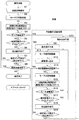
図10は、硬貨の補充処理と解除処理の具体的な手順を示したものである。適宜図1及び図3を参照しながら説明する。最初に係員の手作業により補充庫19に硬貨が補充される(S1)。すると、駆動モータ12が動作し、キャリングディスク5を正方向回転駆動する(S2)。同時に、駆動電流の過電流検出閾値を設定し、補充計数センサ38の計数時間(補充計数タイマタイム)を設定し駆動電流検出及び補充計数センサの検出をスタートする(S3)。尚、補充計数タイマタイムは、通常動作においてキャリングディスク5が回転してから放出されるまでの時間間隔より十分長い時間であって、この時間を経過しても硬貨2が放出されない場合は異常と判断される時間間隔に設定されるもので、典型的には数秒である。駆動モータ12の駆動電流の電流値を駆動電流検出部39で検出し(S4)、所定の電流値以上のときは噛み込み状態であると判断する(S4:YES)。所定の電流値未満のときは(S4:NO)、キャリングディスク5の回転を継続し、放出動作を継続する(S6)。次に、補充計数センサ38の放出硬貨の検出を行い(S7)、放出がない場合(S7:NO)はS4に戻る。以上のステップS4〜S7の動作は補充計数タイマがタイムアップになるまで繰り返される。タイムアップになった場合(S5:YES)掻き揚げ不良が生じていると判断する。補充計数センサ38(図1参照)が遮光され放出硬貨が検出された場合は(S7:YES)正常に放出動作が行われると判断し、エンドセンサ13(図1参照)により補充庫19の残存硬貨の有無を確認し(S8)、硬貨が残存している場合は(S8:YES)ステップS3に戻る。この一連の動作(S3〜S8)は、補充硬貨が補充庫19から無くなるまで継続される。補充硬貨の放出/停止の制御は制御部40によって行われ停止の指令があるまでは硬貨放出が継続される。   FIG. 10 shows a specific procedure for coin replenishment processing and release processing. This will be described with reference to FIGS. 1 and 3 as appropriate. Initially, coins are replenished to the replenisher 19 by the staff's manual work (S1). Then, the drive motor 12 operates to drive the carrying disk 5 to rotate in the forward direction (S2). At the same time, the overcurrent detection threshold value of the drive current is set, the count time of the replenishment count sensor 38 (replenishment count timer time) is set, and the detection of the drive current and the replenishment count sensor are started (S3). Note that the replenishment counting timer time is sufficiently longer than the time interval from the rotation of the carrying disk 5 to the release in normal operation, and if the coin 2 is not released even after this time has elapsed, it is abnormal. It is set to the determined time interval and is typically a few seconds. The current value of the drive current of the drive motor 12 is detected by the drive current detector 39 (S4), and when it is equal to or greater than a predetermined current value, it is determined that the biting state is present (S4: YES). When the current value is less than the predetermined current value (S4: NO), the carrying disk 5 continues to rotate and the discharge operation continues (S6). Next, the coins discharged from the replenishment counting sensor 38 are detected (S7). If there is no release (S7: NO), the process returns to S4. The above operations in steps S4 to S7 are repeated until the replenishment counting timer expires. When the time is up (S5: YES), it is determined that there is a scraping defect. When the replenishment counting sensor 38 (see FIG. 1) is shielded and a discharged coin is detected (S7: YES), it is determined that the discharging operation is normally performed, and the end sensor 13 (see FIG. 1) keeps the replenishing cabinet 19 remaining. The presence or absence of coins is confirmed (S8), and if coins remain (S8: YES), the process returns to step S3. This series of operations (S3 to S8) is continued until the replenishment coins disappear from the replenishment storage 19. The control of the replenishment coin release / stop is performed by the control unit 40, and the coin release is continued until a stop command is issued.

掻き揚げ不良の場合(S9)では、キャリングディスク5が逆方向回転と正方向回転を繰り返す不良動作回復処理(S9〜S19)に移行する。先ず、駆動モータ12の回転を逆方向回転させる(S11)。この場合の回転角度は適宜設定されるがここでは通常1周未満とする。ブリッジ又は俵状態となっている硬貨2はキャリングディスク5が、異なる位置に設けられ、その高さ、太さ又は形状等の異なる突起6を備えているため、各突起の硬貨への作用が不規則となり各状態を崩すと共に孔4への落とし込みを促すことが出来る(S12)。正方向回転動作で解除できなかった掻き揚げ状態が逆方向回転動作で崩れるのは逆方向回転によって他の硬貨2との衝突条件が正方向回転とは異なるためである。次に、再び正方向回転方向にキャリングディスク5を回転させる(S14)。この正方向回転/逆方向回転動作は予め定めた回数を限度に(本実施の形態では6回)不良動作が解消されるまで繰り返されるが、S12とS14の間で正方向回転/逆方向回転の繰り返し回数をカウントし(S13)、予め定めた回数を超えた場合は(S13:YES)エラーメッセージを発出する。正方向回転/逆方向回転の繰り返し回数が予め定めた回数以下の場合は上述したようにキャリングディスク5を正方向回転駆動し(S14)、S3〜S7と同様の手順で不良動作が回復したかを確認する。即ち、駆動電流の過電流検出の閾値、補充計数タイマを設定し(S15)、駆動電流を検出してロック状態になっていないかを検出し(S16)、補充計数タイマがタイムアップしても硬貨が放出されないことを検出することで掻き揚げ状態があるかを確認し(S17)、ロック又は掻き揚げ状態の場合(S16:YES,S17:YES)には、再びキャリングディスク5を逆方向回転させる(S11)。補充計数タイマがタイムアップ以前であれば、硬貨の放出動作を実行し(S18)、補充計数センサで硬貨の放出を確認し、確認されない場合(S19:NO)放出動作を補充計数タイマ設定値の時間まで繰り返えす。硬貨の放出が確認された場合(S19:YES)、正常動作に回復したと判断しステップS3に戻り、回復処理を終了する。   In the case of a scraping failure (S9), the carrying disk 5 proceeds to a defective operation recovery process (S9 to S19) in which the reverse rotation and the forward rotation are repeated. First, the drive motor 12 is rotated in the reverse direction (S11). The rotation angle in this case is set as appropriate, but here it is usually less than one round. The coin 2 in the bridge or heel state has the carrying disc 5 provided at different positions and provided with projections 6 having different heights, thicknesses, shapes, etc., so that each projection has no effect on the coins. It becomes a rule, and each state is destroyed, and it is possible to promote dropping into the hole 4 (S12). The scraped state that could not be released by the forward rotation operation is broken by the backward rotation operation because the collision condition with other coins 2 is different from the forward rotation by the backward rotation. Next, the carrying disk 5 is rotated again in the forward direction (S14). This forward rotation / reverse rotation operation is repeated up to a predetermined number of times (six times in the present embodiment) until the defective operation is resolved, but forward rotation / reverse rotation between S12 and S14. Is repeated (S13), and if a predetermined number is exceeded (S13: YES), an error message is issued. If the number of forward / reverse rotation repetitions is less than or equal to the predetermined number, the carrying disk 5 is driven to rotate in the forward direction as described above (S14), and the defective operation is recovered in the same procedure as in S3 to S7. Confirm. That is, the threshold value for detecting the overcurrent of the drive current and the replenishment count timer are set (S15), whether the drive current is detected and the lock state is detected (S16), and even if the replenishment count timer expires By detecting that no coin is released, it is confirmed whether or not there is a scraped state (S17). If it is locked or scraped (S16: YES, S17: YES), the carrying disk 5 is again rotated in the reverse direction. (S11). If the replenishment count timer is before time-up, the coin release operation is executed (S18), the coin release is confirmed by the replenishment count sensor, and if it is not confirmed (S19: NO), the release operation is set to the replenishment count timer set value. Repeat until time. When it is confirmed that coins have been released (S19: YES), it is determined that the normal operation has been recovered, and the process returns to step S3 to complete the recovery process.

噛み込み不良(ロック状態)の場合(S10)も同様の処理を行う。噛み込み不良の解除では、逆方向回転駆動により(S11)ロック状態の原因となった突起6とは異なる位置、或いは異なる形状・高さ・太さの突起6が当該ロックの原因となっている硬貨2の近辺の硬貨に作用する。更に、逆回転の回転角度を大きくし、1周以上とするとロック状態の原因となった突起6が当該硬貨2に逆方向に作用し、これらの突起6の作用によりロック状態を崩す機会が増加する。また、逆方向回転/正方向回転の前述した予め定めた回数のうち各回の回転角度をそれぞれ任意な値に設定し、例えば各回で異なるものとすることで硬貨2への作用をより不規則なものとすることが出来、解除の効果を向上することができる。   The same process is performed when the biting is defective (locked state) (S10). In the release of the biting failure, the protrusion 6 having a position different from, or different in shape, height, and thickness from the protrusion 6 causing the locked state by reverse rotation driving (S11) causes the lock. Acts on coins in the vicinity of coin 2. Furthermore, if the rotation angle of the reverse rotation is increased and the rotation angle is more than one, the protrusion 6 that causes the locked state acts on the coin 2 in the reverse direction, and the chance of breaking the locked state by the action of these protrusions 6 increases. To do. Further, the rotation angle of each time is set to an arbitrary value among the predetermined number of times of the reverse rotation / forward rotation, and the action on the coin 2 is made more irregular by making it different at each time, for example. Can be improved, and the effect of cancellation can be improved.

尚、このような回転角度を相違させる点は、掻き揚げ不良の解除にも同様に有効である。また、図10で説明した手順は一例を述べたものであり、各手順の順序を変更したりすることが出来ることは明らかである。また、噛み込み/掻き揚げ不良の検出方法を初めとする各種検出方法はここで述べたものに限定されない。要は、位置や形状、高さ、太さ等が異なる複数の突起6を備えたキャリングディスク5を用いた硬貨放出装置の動作を検出する手段を有し、動作が不良を検出した場合はキャリングディスク5の逆方向回転/正方向回転を行えば良い。   In addition, the point which makes such a rotation angle different is effective similarly also in cancellation | release of a scraping defect. Further, the procedure described in FIG. 10 is an example, and it is obvious that the order of each procedure can be changed. In addition, various detection methods including a detection method for biting / scraping failure are not limited to those described here. In short, it has means for detecting the operation of the coin ejector using the carrying disk 5 provided with a plurality of projections 6 having different positions, shapes, heights, thicknesses, etc. The disk 5 may be rotated in the reverse direction / forward direction.

[硬貨処理装置の構成]
次に、図11を参照して、上述した硬貨放出装置1を使用する硬貨処理装置10の構成について説明する。硬貨処理装置10は、入金口27、入金繰出部28、識別部29、入金搬送部30、硬貨振分部31、一時保留部32、スタッカ部33、補充リジェクト庫34、出金搬送部35、金庫部36、出金口37、硬貨補充部26並びに制御部40を備えている。
[Configuration of coin handling equipment]
Next, with reference to FIG. 11, the structure of the coin processing apparatus 10 which uses the coin discharge | release apparatus 1 mentioned above is demonstrated. The coin processing apparatus 10 includes a deposit port 27, a deposit dispensing unit 28, an identification unit 29, a deposit transport unit 30, a coin distribution unit 31, a temporary storage unit 32, a stacker unit 33, a replenishment reject box 34, a withdrawal transport unit 35, A safe unit 36, a withdrawal port 37, a coin replenishment unit 26, and a control unit 40 are provided.

入金口27は、利用者から投入される一枚または複数枚の硬貨を硬貨処理装置10内に受け付けるものである。
入金繰出部28は、入金口27に一括投入された複数の硬貨を一枚ずつ分離し入金搬送部30へ繰出す。
入金搬送部30は、入金搬送路(不図示)、駆動手段(不図示)、プーリ(不図示)、識別部29などからなり、入金繰出部28から繰出された硬貨を識別し、硬貨振分部31へ搬送する。入金搬送路は、板金や搬送ベルトの組み合わせにより、入金繰出部28より繰出された硬貨を搬送し、搬送ベルトは、略中央に硬貨を挟みこむようにして搬送する。駆動手段は、プーリ、駆動モータなどからなり搬送ベルトを駆動する。識別部29は、投入された硬貨の識別を行うセンサで、内部に検出回路、CPU、データ格納部などを備え、硬貨の真偽と種類を識別し、その識別情報が制御部40に出力される。
The deposit port 27 receives one or a plurality of coins input from the user into the coin processing device 10.
The deposit payout unit 28 separates a plurality of coins put into the deposit port 27 one by one and feeds them to the deposit transport unit 30.
The deposit conveyance unit 30 includes a deposit conveyance path (not shown), a driving means (not shown), a pulley (not shown), an identification unit 29, etc., and identifies the coins fed from the deposit feeding unit 28, and distributes the coins. It conveys to the part 31. The deposit conveyance path conveys coins fed from the deposit feeding section 28 by a combination of sheet metal and a conveyance belt, and the conveyance belt conveys the coins so that the coins are sandwiched between the centers. The drive means is composed of a pulley, a drive motor, etc., and drives the conveyor belt. The identification unit 29 is a sensor that identifies the inserted coin, and includes a detection circuit, a CPU, a data storage unit, and the like, and identifies the authenticity and type of the coin, and the identification information is output to the control unit 40. The

硬貨振分部31は、硬貨を金種別、およびリジェクトすべきものに振分けるもので、振分板(不図示)およびリジェクト部(不図示)を含む。振分板は、金種別の大きさの孔を備え、搬送ベルトにより搬送される硬貨を金種毎に対応する一時保留部32へそれぞれ振り分けるものである。尚、金種振分は振分板に限定されるものではなく、振分爪を複数備えるものであっても良い。リジェクト部は、振分板(不図示)の上流に設けられた振分爪(不図示)、その下方のシュート(不図示)などからなる。入金動作の場合には正硬貨以外の入金をリジェクトし、出金口37に硬貨が振り分けられる。補充動作の場合は補充できない補充硬貨をリジェクトし、補充リジェクト庫34に硬貨を振り分ける。各リジェクト硬貨は識別部29からの識別情報に基づき制御部40から動作タイミングが出力され、図示しない駆動手段(ソレノイド)やリンク機構により振分爪が動作することで振り分けられる。尚、本願発明の場合、入金と補充の切り換えが後述する一時保留部32の入金/補充振り分け手段により行われ、リジェクト部(不図示)の下方のシュートも一時保留部32と同一にユニットに備えられる。   The coin distribution unit 31 distributes coins into denominations and items to be rejected, and includes a distribution plate (not shown) and a reject unit (not shown). The distribution board is provided with a hole of a size of each denomination, and distributes the coins conveyed by the conveyor belt to the temporary storage units 32 corresponding to each denomination. The denomination distribution is not limited to the distribution plate, and may include a plurality of distribution claws. The reject unit includes a sorting claw (not shown) provided upstream of a sorting plate (not shown), a chute (not shown) below it, and the like. In the case of a depositing operation, deposits other than regular coins are rejected, and coins are distributed to the withdrawal port 37. In the case of the replenishment operation, the replenishment coins that cannot be replenished are rejected, and the coins are distributed to the replenishment reject box 34. Each reject coin is output when the operation timing is output from the control unit 40 based on the identification information from the identification unit 29, and is distributed by the movement of the distribution claw by a driving means (solenoid) or a link mechanism (not shown). In the case of the present invention, switching between deposit and replenishment is performed by deposit / replenishment distribution means of the temporary storage unit 32 described later, and a chute below the reject unit (not shown) is provided in the unit in the same manner as the temporary storage unit 32. It is done.

一時保留部32は、利用者の投入した入金硬貨や係員の投入した補充硬貨を一旦保留するもので、図示しない、入金/補充振分手段、シャッタ・仕切板開閉機構、シャッタ位置検知手段、硬貨残留検知手段からなる保留部、保留部を駆動する駆動手段などから構成される。   The temporary storage unit 32 temporarily holds the coins inserted by the user and the replenishment coins inserted by the staff, and includes a deposit / replenishment distribution unit, a shutter / partition plate opening / closing mechanism, a shutter position detection unit, a coin (not shown). It is comprised from the reservation part which consists of a residual detection means, the drive means which drives a reservation part, etc.

スタッカ部33は、金種毎に硬貨を大量に収納し、必要な時に硬貨を外部に放出するもので、放出機構は取引により出金が必要な時や硬貨の回収時毎に作動する。出金硬貨は出金搬送部35を通じて出金口37に送られ、回収硬貨は金庫部36へ送られる。   The stacker unit 33 stores a large amount of coins for each denomination and discharges the coins to the outside when necessary, and the release mechanism operates when a withdrawal is required by a transaction or whenever a coin is collected. The withdrawal coin is sent to the withdrawal port 37 through the withdrawal transport unit 35 and the collected coin is sent to the safe unit 36.

出金搬送部35は、図示しない搬送ベルト、搬送ベルトを駆動するモータなどからなり、スタッカ部33から放出された出金硬貨を搬送する。また、硬貨振分部31でリジェクトされた入金リジェクト硬貨も出金口37まで搬送する。   The dispensing conveyance unit 35 includes a conveyance belt (not shown), a motor that drives the conveyance belt, and the like, and conveys the dispensing coins released from the stacker unit 33. Further, the deposit reject coin rejected by the coin sorting unit 31 is also conveyed to the withdrawal port 37.

出金口37は、接客部分に設けられ、出金搬送部35の搬送ベルトにより返却・出金硬貨が放出される部分である。また、入金リジェクトされた硬貨および入金繰出部28により繰出された硬貨以外の異物なども放出される。   The withdrawal port 37 is provided in the customer service portion, and is a portion from which return / withdrawal coins are discharged by the transport belt of the withdrawal transport unit 35. In addition, the rejected coins and foreign matters other than the coins fed out by the deposit feeding unit 28 are also released.

補充部26は、つり銭の不足等に備えて硬貨を補充するための部分である。前述した硬貨放出装置1と放出動作をモニタするモニタ手段9で構成される。硬貨放出装置1で放出された硬貨は入金搬送部30に合流して搬送され、識別部29で補充硬貨の真偽をチェックした後硬貨振分部31で金種毎に振分けられた後一時保留部32を経てスタッカ部33に収納される。   The replenishment part 26 is a part for replenishing coins in preparation for a shortage of change or the like. It comprises the above-described coin discharge device 1 and monitor means 9 for monitoring the discharge operation. The coins released by the coin discharging device 1 are joined and transported to the deposit transport unit 30, checked for authenticity of the replenished coins by the identification unit 29, and then sorted for each denomination by the coin sorting unit 31. It is stored in the stacker unit 33 through the unit 32.

[硬貨処理装置の動作:入金/返却/回収/補充/出金]
以下に、硬貨処理装置10の動作を説明する。図11(a)は入金および返却の場合の硬貨の流れを示したもので各々実線および破線で示す。
入金、返却の収納手順は以下の通りである。
(ア)利用者からの入金に対して待機する。
(イ)利用者が入金口27へ硬貨を投入すると、図示しない検知器がそれを検知し、硬貨処理装置10の制御部40からの指令により入金処理を開始する。
(ウ)入金口27に投入された硬貨は入金繰出部28に供給される。入金繰出部28は供給された硬貨を収納し、収納した硬貨を1枚ずつ入金搬送部30に繰り出す。
(エ)入金繰出部28から1枚ずつ繰り出された硬貨は入金搬搬送部30で搬送され、入金搬送部30に設けられた識別部29に到達する。
(オ)識別部29は搬送されてきた硬貨の真偽を識別し、識別結果を制御部40に出力する。識別部29を通過した硬貨は引き続き入金搬搬送部30により硬貨振分部31に搬送される。
(カ)硬貨振分部31まで搬送された硬貨は制御部40の信号により、前記(オ)の識別結果に基づいて真硬貨と判別されたものを一時保留部32に一時保留し、それ以外の外国硬貨,処理対象以外の硬貨などを入金リジェクト硬貨として返却する。
(キ)硬貨振分部31と一時保留部32の間に設けた不図示のセンサにより通過枚数を計数する。計数結果は入金データとして制御部40に出力される。
(ク)一時保留部32に保留された硬貨は取引終了によりスタッカ部33へ収納される。ここで、「取引」とは、例えば発券における、入金→発券→つり銭返却、のような一連の行為を言う。
(ケ)利用者が取引を取り消す操作がなされた場合は、一時保留部32に保留された硬貨は出金搬送部35を経由して出金口37に返却される。
[Operation of coin handling equipment: deposit / return / collect / replenish / withdraw]
Below, operation | movement of the coin processing apparatus 10 is demonstrated. FIG. 11A shows the flow of coins in the case of depositing and returning, which are indicated by a solid line and a broken line, respectively.
The deposit and return storage procedures are as follows.
(A) Wait for payment from the user.
(A) When a user inserts a coin into the deposit port 27, a detector (not shown) detects it and starts a deposit process in response to a command from the control unit 40 of the coin processing apparatus 10.
(C) The coins inserted into the deposit port 27 are supplied to the deposit feeding unit 28. The deposit feeding unit 28 stores the supplied coins and feeds the stored coins one by one to the deposit transport unit 30.
(D) Coins fed one by one from the deposit feeding section 28 are transported by the deposit transport section 30 and reach the identification section 29 provided in the deposit transport section 30.
(E) The identifying unit 29 identifies the authenticity of the conveyed coin and outputs the identification result to the control unit 40. The coins that have passed through the identification unit 29 are continuously conveyed to the coin distribution unit 31 by the depositing and conveying unit 30.
(F) The coins conveyed to the coin distribution unit 31 are temporarily stored in the temporary storage unit 32 according to the signal of the control unit 40 and are determined to be true coins based on the identification result of (e) above. Foreign coins, non-processing coins, etc. are returned as deposit reject coins.
(G) The number of passing sheets is counted by a sensor (not shown) provided between the coin distribution unit 31 and the temporary storage unit 32. The counting result is output to the control unit 40 as deposit data.
(H) The coins held in the temporary holding unit 32 are stored in the stacker unit 33 when the transaction ends. Here, “transaction” refers to a series of actions such as deposit → ticketing → return of change in ticketing, for example.
(G) When the user performs an operation to cancel the transaction, the coins held in the temporary holding unit 32 are returned to the withdrawal port 37 via the withdrawal transport unit 35.

次に、硬貨の回収における動作を図1(a)を参照して説明する。図中、点線でその流れを示す。
(コ)係員により硬貨処理装置10の回収操作がなされる。
(サ)スタッカ部33の放出機構で振分爪(不図示)を作動させ回収側として硬貨を放出する。
(シ)スタッカ部33から放出された硬貨は金庫部36に収納される。
Next, the operation | movement in collection | recovery of a coin is demonstrated with reference to Fig.1 (a). The flow is shown by dotted lines in the figure.
(G) A collection operation of the coin processing device 10 is performed by an attendant.
(S) The sorting claw (not shown) is operated by the release mechanism of the stacker unit 33 to release coins as the collecting side.
(Sh) Coins released from the stacker unit 33 are stored in the safe unit 36.

次に、硬貨の補充処理動作及び補充リジェクト動作を図11(b)を参照して説明する。尚、前者の流れを一点鎖線で、後者の流れを二点鎖線で示す。
(ス)係員により硬貨処理装置10の補充部26(硬貨放出装置1を含む部分)に補充硬貨が収納される。
(セ)硬貨補充装置26は供給された硬貨を収納し、収納した硬貨を1枚ずつ図示しない補充搬送部に繰出す。1枚ずつ繰出すのは識別部29において振分の確実性を確保するためである。
(ソ)硬貨は補充搬送路から入金搬送部30に合流して搬送され、入金搬送別部30に設けられた識別部29に到着する。
(タ)識別部29は搬送されてきた硬貨の真偽を識別し、識別結果を制御部40に出力する。識別部29を通過した硬貨は硬貨振分部31へ搬送される。
(チ)硬貨振分部31まで搬送された硬貨は制御部40の指令に基づき、真硬貨と判別されたものを一時保留部32に一時保留し、それ以外のものは補充リジェクト硬貨として補充リジェクト部34に振り分けられる。
(ツ)硬貨振分部31と一時保留部32の間には図示しないセンサが設けられており、通過硬貨の枚数を計数する。この計数結果は補充データとして制御部40へ出力される。
(テ)一時保留部32に保留された硬貨は、補充終了または所定補充枚数ごとにスタッカ部33へ収納される。尚、ここでの「所定補充枚数」は、本発明では30枚程度である。
(ト)何らかの理由により補充が中止された場合には、一時保留部32に保留されている硬貨(補充搬送路に残っているものを含む)は補充リジェクト部34に収納される。
Next, a coin replenishment processing operation and a replenishment reject operation will be described with reference to FIG. The former flow is indicated by a one-dot chain line, and the latter flow is indicated by a two-dot chain line.
(S) The replenishment coins are stored in the replenishment section 26 (part including the coin discharge device 1) of the coin processing device 10 by the attendant.
(C) The coin replenishing device 26 stores the supplied coins, and feeds the stored coins one by one to a replenishing conveyance unit (not shown). The reason for feeding out one sheet at a time is to ensure the certainty of distribution in the identification unit 29.
(Seo) Coins are transferred from the replenishment conveyance path to the deposit conveyance unit 30 and conveyed, and arrive at the identification unit 29 provided in the deposit conveyance separate unit 30.
(T) The identification unit 29 identifies the authenticity of the coins that have been conveyed, and outputs the identification result to the control unit 40. Coins that have passed through the identification unit 29 are conveyed to the coin distribution unit 31.
(H) Based on the command of the control unit 40, the coins conveyed to the coin distribution unit 31 are temporarily stored in the temporary storage unit 32, and the other coins are replenished and rejected as supplementary reject coins. It is distributed to the part 34.
(Iv) A sensor (not shown) is provided between the coin distribution unit 31 and the temporary storage unit 32, and counts the number of coins passed. The counting result is output to the control unit 40 as supplementary data.
(T) Coins held in the temporary holding unit 32 are stored in the stacker unit 33 after completion of replenishment or every predetermined number of replenished sheets. Here, the “predetermined replenishment number” is about 30 in the present invention.
(G) When replenishment is stopped for some reason, the coins (including those remaining in the replenishment conveyance path) held in the temporary holding unit 32 are stored in the replenishment reject unit 34.

次に、硬貨出金における動作を図11(b)を参照して説明する。尚、動作の流れを破線で示す。
(ナ)制御部40は入金された金額と、例えば利用者の操作で確定された取引に必要な金額とを比較して、余剰金額即ち出金に必要な硬貨の金種と各々の金種の枚数を算出する。
(ニ)制御部40は上記算出結果に基づいて、出金が不要の場合には出金処理を行わず動作を終了し、入金に対して待機する。
(ヌ)制御部40は出金が必要な場合には、該当する金種のスタッカ部33へ必要枚数の繰り出しを指示する払い出し指示信号を出力する。これによりスタッカ部33の各スタッカは必要枚数の硬貨を出金搬送部35に放出する。
(ネ)出金搬送部35に放出された硬貨は出金口37まで搬送され、出金処理が終了する。
Next, the operation in coin dispensing will be described with reference to FIG. The operation flow is indicated by a broken line.
(N) The control unit 40 compares the deposited amount with, for example, the amount necessary for the transaction determined by the user's operation, and the surplus amount, that is, the denomination of coins necessary for withdrawal and each denomination The number of sheets is calculated.
(D) Based on the above calculation result, the control unit 40 ends the operation without performing the withdrawal process when the withdrawal is unnecessary, and waits for the deposit.
(Nu) When the withdrawal is required, the control unit 40 outputs a payout instruction signal for instructing the delivery of the necessary number of sheets to the stacker unit 33 of the corresponding denomination. As a result, each stacker of the stacker unit 33 discharges a required number of coins to the dispensing transport unit 35.
(E) The coins released to the withdrawal transport unit 35 are transported to the withdrawal port 37, and the withdrawal process is completed.

図11(c)は、各部と制御部40との制御信号関係を示したものである。各部は制御部40とバス接続される。   FIG. 11C shows a control signal relationship between each unit and the control unit 40. Each unit is connected to the control unit 40 by a bus.

以上説明した硬貨処理装置10は、本願の発明である硬貨放出装置1を補充部26に適用した実施の形態である。しかし、本願発明は、この実施の形態に限定されるだけではなく、本硬貨放出装置1をスタッカ部33に適用することも出来る。また、以上説明した複数の実施の形態は、個々で説明した構成の範囲に限定されるものではなく、各々の実施の形態を適宜組み合わせてもよい。   The coin processing device 10 described above is an embodiment in which the coin discharging device 1 according to the invention of the present application is applied to the replenishing unit 26. However, the present invention is not limited to this embodiment, and the present coin discharge device 1 can also be applied to the stacker unit 33. Further, the plurality of embodiments described above are not limited to the scope of the configuration described individually, and the embodiments may be appropriately combined.

本発明の硬貨放出装置の主要部を示す模式図The schematic diagram which shows the principal part of the coin discharge | release apparatus of this invention 本発明キャリングディスクを示す図The figure which shows this invention carrying disk 本発明の硬貨処理装置の動作を示す図The figure which shows operation | movement of the coin processing apparatus of this invention. ロック状態を説明する図Diagram explaining the locked state ブリッジ状態を説明する図Diagram explaining the bridge state 俵状態を説明する図Diagram explaining the heel state 同期状態を説明する図Diagram explaining the synchronization state 本発明によるロック状態を解除する場合の動作を説明する図The figure explaining operation | movement in the case of canceling | releasing the lock state by this invention 本発明による俵状態、及び同期状態を解除する場合の動作を説明する図The figure explaining the operation | movement in the case of canceling | disabling the heel state by this invention, and a synchronous state 本発明の硬貨放出装置の動作、及び異常状態を回復させる手順を示した図The figure which showed the procedure of recovering the operation | movement of the coin discharge | release apparatus of this invention, and an abnormal state 本発明の硬貨処理装置の構成と動作を示した図The figure which showed the structure and operation | movement of the coin processing apparatus of this invention. 従来の硬貨放出装置の構造の例Example of structure of conventional coin dispenser

符号の説明Explanation of symbols

1 硬貨放出装置
2 硬貨
3 ベース部
3a 摺動面
4 孔
5 キャリングディスク
6 突起
7 放出口
8 凹部
9 モニタ手段
10 硬貨処理装置
11 ギアヘッド
12 駆動モータ
13 エンドセンサ
14 中央凸部
15 送出ローラ
16 送出ガイド
17 駆動軸
19 補充庫(硬貨収納部)
19a 補充庫底部
20 補充口
21 段差
22 手裏剣状の部位
23 段差
24 ゲートピン
25 溝
26 補充部
27 入金口
28 入金繰出部
29 識別部
30 入金搬送部
31 硬貨振分部
32 一時保留部
33 スタッカ部
34 補充リジェクト庫
35 出金搬送部
36 金庫部
37 出金口
38 補充計数センサ
39 駆動電流検出部
40 制御部
DESCRIPTION OF SYMBOLS 1 Coin discharge | emission apparatus 2 Coin 3 Base part 3a Sliding surface 4 Hole 5 Carrying disk 6 Protrusion 7 Ejection port 8 Recess 9 Monitor means 10 Coin processing apparatus 11 Gear head 12 Drive motor 13 End sensor 14 Central convex part 15 Sending roller 16 Sending guide 16 17 Drive shaft 19 Replenisher (coin storage)
19a Replenishment warehouse bottom portion 20 Replenishment port 21 Step 22 Shuriken-shaped part 23 Step 24 Gate pin 25 Groove 26 Replenishment unit 27 Deposit port 28 Deposit feeding unit 29 Identification unit 30 Deposit transport unit 31 Coin sorting unit 32 Temporary storage unit 33 Stacker unit 34 Replenishment reject box 35 Withdrawal transport unit 36 Safe unit 37 Withdrawal port 38 Replenishment counting sensor 39 Drive current detection unit 40 Control unit

Claims (3)

硬貨が摺動して移動する平坦な摺動面を有するベース部と;
前記摺動面に平行に配置され、前記摺動面に沿って予め定められた正方向に回転運動をし、前記硬貨が納まる複数の孔が形成され、該孔に納まった前記硬貨を前記回転運動により前記摺動面に沿って移動することで前記硬貨を1枚ずつ、外部に放出するキャリングディスクと;
前記摺動面と対向する面と反対側の前記キャリングディスクの面に、前記回転運動の中心以外に固定配置された複数の突起であって、該突起のうち少なくとも1つの前記回転運動の中心からの距離が他の突起の前記回転中心からの距離と異なり、かつ、前記突起のうち少なくとも1つの形状、高さ、または太さが他の突起と異なる突起と;
を備える、硬貨放出装置。
A base portion having a flat sliding surface on which coins slide and move;
A plurality of holes that are arranged in parallel to the sliding surface and rotate in a predetermined positive direction along the sliding surface to store the coins are formed, and the coins that are stored in the holes are rotated. A carrying disk for releasing the coins one by one by moving along the sliding surface by movement;
A plurality of protrusions fixedly disposed on the surface of the carrying disk opposite to the surface facing the sliding surface, other than the center of the rotational movement, from at least one center of the rotational movement among the protrusions And a protrusion whose at least one of the protrusions is different in shape, height, or thickness from the other protrusions;
A coin discharge device.
前記硬貨放出装置の放出動作をモニタするモニタ手段と;
該モニタ手段により、前記放出動作が異常であると判断される場合、前記キャリングディスクの回転方向を逆方向に回転させて、前記放出動作を正常状態に回復させる手段;
を備える、請求項1記載の硬貨放出装置。
Monitoring means for monitoring the discharging operation of the coin discharging device;
Means for recovering the discharge operation to a normal state by rotating the rotation direction of the carrying disk in the reverse direction when the monitor means determines that the discharge operation is abnormal;
The coin discharge device according to claim 1, comprising:
請求項1または請求項2のいずれか1項に記載の硬貨放出装置と;
前記硬貨放出装置を含む補充部から1枚ずつ放出された硬貨を、硬貨振分部に搬送する入金搬送部;
を備える硬貨処理装置。
A coin discharge device according to any one of claims 1 or 2;
A deposit transport unit for transporting coins released one by one from the replenishment unit including the coin discharge device to the coin distribution unit;
A coin processing apparatus.
JP2008213788A 2008-08-22 2008-08-22 Coin discharging apparatus and coin processing apparatus Active JP5258452B2 (en)

Priority Applications (1)

Application Number Priority Date Filing Date Title
JP2008213788A JP5258452B2 (en) 2008-08-22 2008-08-22 Coin discharging apparatus and coin processing apparatus

Applications Claiming Priority (1)

Application Number Priority Date Filing Date Title
JP2008213788A JP5258452B2 (en) 2008-08-22 2008-08-22 Coin discharging apparatus and coin processing apparatus

Publications (2)

Publication Number Publication Date
JP2010049527A true JP2010049527A (en) 2010-03-04
JP5258452B2 JP5258452B2 (en) 2013-08-07

Family

ID=42066554

Family Applications (1)

Application Number Title Priority Date Filing Date
JP2008213788A Active JP5258452B2 (en) 2008-08-22 2008-08-22 Coin discharging apparatus and coin processing apparatus

Country Status (1)

Country Link
JP (1) JP5258452B2 (en)

Cited By (1)

* Cited by examiner, † Cited by third party
Publication number Priority date Publication date Assignee Title
JP2012185639A (en) * 2011-03-04 2012-09-27 Toshiba Tec Corp Coin processor, coin processing system and program

Citations (4)

* Cited by examiner, † Cited by third party
Publication number Priority date Publication date Assignee Title
JPH0467775U (en) * 1990-10-23 1992-06-16
JPH11250297A (en) * 1998-02-26 1999-09-17 Takamisawa Cybernetics Co Ltd Coin feeding device, coin processor and coin feeding method
JP2001216554A (en) * 2000-02-02 2001-08-10 Glory Ltd Coin processor
JP2005027747A (en) * 2003-07-08 2005-02-03 Sanyo Electric Co Ltd Coin-like member put-out device

Patent Citations (4)

* Cited by examiner, † Cited by third party
Publication number Priority date Publication date Assignee Title
JPH0467775U (en) * 1990-10-23 1992-06-16
JPH11250297A (en) * 1998-02-26 1999-09-17 Takamisawa Cybernetics Co Ltd Coin feeding device, coin processor and coin feeding method
JP2001216554A (en) * 2000-02-02 2001-08-10 Glory Ltd Coin processor
JP2005027747A (en) * 2003-07-08 2005-02-03 Sanyo Electric Co Ltd Coin-like member put-out device

Cited By (1)

* Cited by examiner, † Cited by third party
Publication number Priority date Publication date Assignee Title
JP2012185639A (en) * 2011-03-04 2012-09-27 Toshiba Tec Corp Coin processor, coin processing system and program

Also Published As

Publication number Publication date
JP5258452B2 (en) 2013-08-07

Similar Documents

Publication Publication Date Title
JPH07129804A (en) Exchanging machine
JP2009075749A (en) Coin depositing and dispensing machine
JP6270443B2 (en) Money changer
JP2018147271A (en) Coin processing device and coin depositing/dispensing device including the same
JP5258452B2 (en) Coin discharging apparatus and coin processing apparatus
JP2009059309A (en) Cash dispenser
JP2008018151A (en) Token processor having token selection device, token deposit/pay-out device, and token lending machine
JP3679017B2 (en) Coin change machine
JP6317560B2 (en) Coin processing equipment
JP2000113275A (en) Coin receiving and paying machine
JP4163918B2 (en) Coin storage and feeding device
JPH10208107A (en) Coin reception device and circular coin receiving/paying machine
JP2004110632A (en) Coin storage/pay-out cassette and coin processing machine
JP4376547B2 (en) Coin dispenser
JP2009075750A (en) Coin depositing machine
JP3248849B2 (en) Coin depositing and dispensing machine
JP3663042B2 (en) Coin deposit / withdrawal device
JP3258571B2 (en) Coin depositing and dispensing machine
JP5368128B2 (en) Coin processing equipment
JP3456857B2 (en) Coin sorting equipment
WO2015083682A1 (en) Coin package discharge device
JP3086681B2 (en) Coin processing equipment
JP3320989B2 (en) Coin depositing and dispensing machine
JP3258574B2 (en) Coin depositing and dispensing machine
JP2015130141A (en) Packed coin pay-out device

Legal Events

Date Code Title Description
A621 Written request for application examination

Free format text: JAPANESE INTERMEDIATE CODE: A621

Effective date: 20110802

A977 Report on retrieval

Free format text: JAPANESE INTERMEDIATE CODE: A971007

Effective date: 20130219

TRDD Decision of grant or rejection written
A01 Written decision to grant a patent or to grant a registration (utility model)

Free format text: JAPANESE INTERMEDIATE CODE: A01

Effective date: 20130402

A61 First payment of annual fees (during grant procedure)

Free format text: JAPANESE INTERMEDIATE CODE: A61

Effective date: 20130423

FPAY Renewal fee payment (event date is renewal date of database)

Free format text: PAYMENT UNTIL: 20160502

Year of fee payment: 3

R150 Certificate of patent or registration of utility model

Ref document number: 5258452

Country of ref document: JP

Free format text: JAPANESE INTERMEDIATE CODE: R150

Free format text: JAPANESE INTERMEDIATE CODE: R150