JP2010048450A - Leaked steam heat recovery structure from steam motor shaft seal part - Google Patents

Leaked steam heat recovery structure from steam motor shaft seal part Download PDF

Info

Publication number
JP2010048450A
JP2010048450A JP2008212124A JP2008212124A JP2010048450A JP 2010048450 A JP2010048450 A JP 2010048450A JP 2008212124 A JP2008212124 A JP 2008212124A JP 2008212124 A JP2008212124 A JP 2008212124A JP 2010048450 A JP2010048450 A JP 2010048450A
Authority
JP
Japan
Prior art keywords
steam
water
shaft seal
motor
leaked
Prior art date
Legal status (The legal status is an assumption and is not a legal conclusion. Google has not performed a legal analysis and makes no representation as to the accuracy of the status listed.)
Granted
Application number
JP2008212124A
Other languages
Japanese (ja)
Other versions
JP5256932B2 (en
Inventor
Yasukuni Tanaka
靖国 田中
Yusuke Okamoto
裕介 岡本
Kazuyuki Otani
和之 大谷
Current Assignee (The listed assignees may be inaccurate. Google has not performed a legal analysis and makes no representation or warranty as to the accuracy of the list.)
Miura Co Ltd
Original Assignee
Miura Co Ltd
Priority date (The priority date is an assumption and is not a legal conclusion. Google has not performed a legal analysis and makes no representation as to the accuracy of the date listed.)
Filing date
Publication date
Application filed by Miura Co Ltd filed Critical Miura Co Ltd
Priority to JP2008212124A priority Critical patent/JP5256932B2/en
Publication of JP2010048450A publication Critical patent/JP2010048450A/en
Application granted granted Critical
Publication of JP5256932B2 publication Critical patent/JP5256932B2/en
Active legal-status Critical Current
Anticipated expiration legal-status Critical

Links

Images

Abstract

<P>PROBLEM TO BE SOLVED: To recover heat of leaked steam from a shaft seal part of a screw-type steam motor. <P>SOLUTION: The screw-type steam motor 4 generating power by using steam from a boiler 2 drives an oil lubricated type air compressor 5. A heat exchanger 23 and an ejector 35 are provided in a make-up water passage 8 to a water feed tank 7 of the boiler 2. In the heat exchanger 23, indirect heat exchange is performed between lubricating oil and compressed air in the compressor 5 and make-up water to the water feed tank 7. In the ejector 35, water is sprayed from a nozzle 36 to a diffuser 37, and leaked steam from the shaft seal part of the steam motor 4 is sucked to the make-up water passage 8 via a leaked steam passage 39. Thus, the leaked steam is mixed with the make-up water to the water feed tank 7, to promote preheating of water supply to the boiler 2. <P>COPYRIGHT: (C)2010,JPO&INPIT

Description

本発明は、スクリュ式スチームモータの軸封部からの漏れ蒸気を有効利用するための構造に関するものである。特に、スクリュ式スチームモータの軸封部からの漏れ蒸気を利用して、ボイラへの給水の予熱を図るための漏れ蒸気熱回収構造に関するものである。   The present invention relates to a structure for effectively using leaked steam from a shaft seal portion of a screw type steam motor. In particular, the present invention relates to a leakage steam heat recovery structure for preheating water supply to a boiler using leakage steam from a shaft seal portion of a screw type steam motor.

下記特許文献1には、スクリュ型膨張機(1)により空気圧縮機(2)を駆動し、空気圧縮機(2)の負荷変動に際してはスクリュ型膨張機(1)に流入する蒸気を加減弁(10)により制御して対応すると共に、スクリュ型膨張機(1)の蒸気流入側と蒸気流出側との間に設けたバイパス弁(9)を制御することにより、前記負荷変動に拘らず蒸気流出側における蒸気の背圧を一定に保持する方法が開示されている。ここで、バイパス弁(9)の制御は、スクリュ型膨張機(1)からの蒸気出口管(5)の背圧を検出器(20)により検出してなされる。また、加減弁(10)の制御は、スクリュ型膨張機(1)の駆動軸の回転数を検出器(23)により検出してなされる。
特開昭63−45403号公報 (特許請求の範囲、公報第2頁右上欄第15行−左下欄第5行、図面)
In Patent Document 1 below, an air compressor (2) is driven by a screw expander (1), and when the load of the air compressor (2) varies, the steam flowing into the screw expander (1) is controlled. (10) is controlled and responded, and by controlling the bypass valve (9) provided between the steam inflow side and the steam outflow side of the screw expander (1), A method of keeping the back pressure of steam on the outflow side constant is disclosed. Here, the bypass valve (9) is controlled by detecting the back pressure of the steam outlet pipe (5) from the screw expander (1) by the detector (20). The control of the adjusting valve (10) is performed by detecting the rotational speed of the drive shaft of the screw expander (1) with the detector (23).
JP-A-63-45403 (Claims, page 2, page 2, upper right column, line 15-lower left column, line 5, drawing)

スクリュ式スチームモータ(スクリュ型膨張機)は、一般に、互いにかみ合うスクリュロータが、中空ケーシング内に回転自在に保持されて構成される。そして、ケーシング内へ導入される蒸気により、スクリュロータが回転され、回転動力を出力する。スクリュロータ同士は、タイミングギアを介して連動回転するが、そのタイミングギアの潤滑油が蒸気と混合しないように、ロータ本体部とタイミングギアとの間で、蒸気を最小限の量だがケーシング外へ漏らしながら、軸封が保たれる。そのために、軸封部には、ラビリンスシールやビスコシールなどの非接触シールが用いられる。   A screw-type steam motor (screw-type expander) is generally configured such that screw rotors that mesh with each other are rotatably held in a hollow casing. Then, the screw rotor is rotated by the steam introduced into the casing and outputs rotational power. The screw rotors rotate in conjunction with each other via a timing gear. The shaft seal is maintained while leaking. Therefore, a non-contact seal such as a labyrinth seal or a visco seal is used for the shaft seal.

このように、スクリュ式スチームモータは、軸封部から蒸気を漏らしながら運転される。従来、この漏れ蒸気は単に大気に排気されており、エネルギーの無駄となっていた。そこで、本発明が解決しようとする課題は、スクリュ式スチームモータの軸封部からの漏れ蒸気の熱を有効利用することにある。この際、スクリュ式スチームモータは前述したように運転時に軸封部から蒸気を漏らすこと自体は必要であるから、その蒸気の漏れを阻害しないよう配慮するのが好ましい。すなわち、前記非接触シールの背圧を上昇させると、潤滑油と蒸気との混合、軸封部の破損のおそれがあるため、その点に配慮するのが好ましい。   Thus, the screw type steam motor is operated while leaking steam from the shaft seal. Conventionally, this leaked steam is simply exhausted to the atmosphere, which is a waste of energy. Therefore, the problem to be solved by the present invention is to effectively utilize the heat of the leaked steam from the shaft seal portion of the screw type steam motor. At this time, the screw-type steam motor needs to leak the steam from the shaft seal portion during operation as described above, and therefore it is preferable to take care not to inhibit the leakage of the steam. That is, if the back pressure of the non-contact seal is increased, there is a risk of mixing the lubricating oil and steam and the shaft seal portion being damaged.

本発明は、前記課題を解決するためになされたもので、請求項1に記載の発明は、蒸気を用いて動力を起こすスクリュ式スチームモータの軸封部から漏れる蒸気を、その漏れ蒸気の熱を利用したい箇所へ供給することを特徴とするスチームモータ軸封部からの漏れ蒸気熱回収構造である。   SUMMARY OF THE INVENTION The present invention has been made to solve the above-mentioned problems. The invention according to claim 1 is directed to the heat leaked from steam leaked from a shaft seal portion of a screw steam motor that generates power using steam. Is a steam heat recovery structure leaking from the shaft seal portion of the steam motor.

請求項1に記載の発明によれば、スクリュ式スチームモータの軸封部からの漏れ蒸気を有効利用して、蒸気利用システムの熱効率を向上することができる。   According to the first aspect of the present invention, it is possible to effectively use the leaked steam from the shaft seal portion of the screw-type steam motor to improve the thermal efficiency of the steam utilization system.

請求項2に記載の発明は、ボイラへの給水タンクの貯留水内に、前記スチームモータの軸封部からの漏れ蒸気を供給することを特徴とする請求項1に記載のスチームモータ軸封部からの漏れ蒸気熱回収構造である。   The invention according to claim 2 supplies steam leaking from the shaft seal portion of the steam motor into the stored water of the water supply tank to the boiler. The steam motor shaft seal portion according to claim 1 This is a heat recovery structure for leaking steam from

請求項2に記載の発明によれば、スクリュ式スチームモータの軸封部からの漏れ蒸気を、ボイラへの給水タンクに供給することで、ボイラへの給水を予熱することができる。   According to invention of Claim 2, the water supply to a boiler can be pre-heated by supplying the leakage steam from the shaft seal part of a screw type steam motor to the water supply tank to a boiler.

請求項3に記載の発明は、ボイラへの給水タンクまたはこの給水タンクへの補給水路に、間接熱交換器を設け、この間接熱交換器に前記スチームモータの軸封部からの漏れ蒸気を通して、前記給水タンクの水または前記補給水路の水を加熱することを特徴とする請求項1に記載のスチームモータ軸封部からの漏れ蒸気熱回収構造である。   The invention according to claim 3 is provided with an indirect heat exchanger in a water supply tank to the boiler or a replenishment water channel to the water supply tank, and through the leaked steam from the shaft seal portion of the steam motor through the indirect heat exchanger, The leak steam heat recovery structure from a steam motor shaft seal according to claim 1, wherein water in the water supply tank or water in the makeup water channel is heated.

請求項3に記載の発明によれば、スクリュ式スチームモータの軸封部からの漏れ蒸気と、給水タンクの貯留水もしくは給水タンクへの補給水とを間接熱交換することで、ボイラへの給水を予熱することができる。   According to the invention described in claim 3, water supply to the boiler is performed by indirect heat exchange between the steam leaked from the shaft seal portion of the screw-type steam motor and the water stored in the water supply tank or the makeup water supplied to the water supply tank. Can be preheated.

請求項4に記載の発明は、ボイラの給水タンクへの補給水路内に、前記スチームモータの軸封部からの漏れ蒸気を供給することを特徴とする請求項1に記載のスチームモータ軸封部からの漏れ蒸気熱回収構造である。   Invention of Claim 4 supplies the leakage steam from the shaft seal part of the said steam motor in the replenishment water path to the water supply tank of a boiler, The steam motor shaft seal part of Claim 1 characterized by the above-mentioned. This is a heat recovery structure for leaking steam from

請求項4に記載の発明によれば、ボイラへの補給水路に、軸封部からの漏れ蒸気路が接続される。これにより、補給水路内の通水に、漏れ蒸気を円滑に導入して、ボイラへの給水を予熱することができる。ところで、漏れ蒸気を直接に給水タンクに回収した場合、蒸気の吹き上げを生じる。従って、その分だけ、熱の回収率が下がることになる。これに対し、請求項4に記載の発明によれば、給水タンクへの補給水路の中途に、軸封部からの漏れ蒸気が混入される。これにより、大気中へ逃げる蒸気量が軽減され、結果として、熱の回収率を向上することができる。しかも、ボイラへの補給水路と、軸封部からの漏れ蒸気路とは、少なくとも一部において配管が共通化されるので、構成の簡素化とコストの低減とを図ることができる。   According to the fourth aspect of the present invention, the leakage steam path from the shaft seal portion is connected to the supply water path to the boiler. Thereby, leaking steam can be smoothly introduced into the water flow in the make-up water channel, and the water supply to the boiler can be preheated. By the way, when the leaked steam is directly collected in the water supply tank, the steam is blown up. Accordingly, the heat recovery rate is lowered by that amount. On the other hand, according to the invention described in claim 4, the leaked steam from the shaft seal portion is mixed in the supply water path to the water supply tank. Thereby, the amount of steam escaping into the atmosphere is reduced, and as a result, the heat recovery rate can be improved. In addition, since the supply water channel to the boiler and the leakage steam channel from the shaft seal are shared at least in part, the configuration can be simplified and the cost can be reduced.

請求項5に記載の発明は、前記補給水路の中途に、エゼクタを設け、前記補給水路に通水して、前記エゼクタにより、前記スチームモータの軸封部からの漏れ蒸気を前記補給水路内へ吸入することを特徴とする請求項4に記載のスチームモータ軸封部からの漏れ蒸気熱回収構造である。   According to a fifth aspect of the present invention, an ejector is provided in the middle of the replenishing water channel, water is passed through the replenishing water channel, and the ejector causes leakage steam from the shaft seal portion of the steam motor to enter the replenishing water channel. The steam heat recovery structure leaking from the steam motor shaft seal according to claim 4, wherein the steam is sucked.

請求項5に記載の発明によれば、ボイラへの補給水路と軸封部からの漏れ蒸気路との合流部にエゼクタを設置し、補給水路に通水することで、エゼクタにより漏れ蒸気を補給水路内へ引き込むことができる。これにより、補給水路内の通水に、漏れ蒸気を一層円滑に導入して、ボイラへの給水を予熱することができる。   According to the fifth aspect of the present invention, the ejector is installed at the junction of the replenishment water channel to the boiler and the leakage steam channel from the shaft seal, and the leakage water is replenished by the ejector by passing water through the replenishment water channel. Can be drawn into the waterway. Thereby, leaking steam can be introduced more smoothly into the water flow in the make-up water channel, and the water supply to the boiler can be preheated.

請求項6に記載の発明は、前記スチームモータの軸封部からの漏れ蒸気を前記補給水路へ供給する漏れ蒸気路は、この漏れ蒸気路内の圧力が設定以上になると大気に開放されることを特徴とする請求項4または請求項5に記載のスチームモータ軸封部からの漏れ蒸気熱回収構造である。   According to a sixth aspect of the present invention, the leakage steam passage that supplies the leakage steam from the shaft seal portion of the steam motor to the makeup water passage is opened to the atmosphere when the pressure in the leakage steam passage becomes equal to or higher than a set value. The steam heat recovery structure for leaking steam from the shaft seal portion of the steam motor according to claim 4 or 5.

請求項6に記載の発明によれば、漏れ蒸気路内の圧力が高まると、漏れ蒸気を大気へ排気することで、軸封部からの蒸気の漏れは阻害されない。従って、補給水路の通水が間欠的になされたり、補給水路内の通水量が変化したりしても、潤滑油と蒸気との混合を防止すると共に軸封部の破損を防止しつつ、ボイラへの給水の予熱を図ることができる。   According to the sixth aspect of the present invention, when the pressure in the leakage steam path increases, the leakage of the steam from the shaft seal portion is not inhibited by exhausting the leakage steam to the atmosphere. Therefore, even if the water flow in the make-up water channel is made intermittently or the water flow amount in the make-up water channel changes, the mixing of the lubricating oil and steam is prevented and the shaft seal portion is prevented from being damaged. Preheating water can be preheated.

請求項7に記載の発明は、前記スチームモータの軸封部からの漏れ蒸気を前記補給水路へ供給する漏れ蒸気路にポンプを設けて漏れ蒸気を前記補給水路へ吐出するか、前記補給水路の中途にポンプを設けて漏れ蒸気を前記補給水路へ吸入することを特徴とする請求項4に記載のスチームモータ軸封部からの漏れ蒸気熱回収構造である。   According to a seventh aspect of the present invention, a pump is provided in a leakage steam path for supplying leakage steam from the shaft seal portion of the steam motor to the makeup water path, and the leakage steam is discharged into the makeup water path, or The leak steam heat recovery structure from the steam motor shaft seal according to claim 4, wherein a pump is provided in the middle to suck the leaked steam into the makeup water channel.

請求項7に記載の発明によれば、漏れ蒸気路または補給水路にポンプを設けることで、軸封部からの蒸気の漏れは阻害されない。従って、補給水路の通水が間欠的になされたり、補給水路内の通水量が変化したりしても、潤滑油と蒸気との混合を防止すると共に軸封部の破損を防止しつつ、ボイラへの給水の予熱を図ることができる。   According to invention of Claim 7, the leak of the vapor | steam from a shaft seal part is not inhibited by providing a pump in a leakage steam channel or a supplementary water channel. Therefore, even if the water flow in the make-up water channel is made intermittently or the water flow amount in the make-up water channel changes, the mixing of the lubricating oil and steam is prevented and the shaft seal portion is prevented from being damaged. Preheating water can be preheated.

さらに、請求項8に記載の発明は、前記補給水路の水は、前記スチームモータにより駆動される油潤滑式の圧縮機からの被冷却流体としての圧縮空気および/または潤滑油を冷却後、前記スチームモータの軸封部からの漏れ蒸気で加熱されて、前記給水タンクへ供給されることを特徴とする請求項3〜7のいずれか1項に記載のスチームモータ軸封部からの漏れ蒸気熱回収構造である。   Further, in the invention according to claim 8, the water in the replenishing water channel is cooled after cooling compressed air and / or lubricating oil as a fluid to be cooled from an oil lubricated compressor driven by the steam motor. The steam leaked from the steam motor shaft seal according to any one of claims 3 to 7, wherein the steam vapor is heated by the steam leaked from the shaft seal of the steam motor and supplied to the water supply tank. It is a recovery structure.

請求項8に記載の発明によれば、スチームモータにより駆動される圧縮機からの被冷却流体としての圧縮空気および/または潤滑油の冷却と、スチームモータの軸封部からの漏れ蒸気からの熱回収とを、効率的に行うことができる。   According to the eighth aspect of the present invention, the cooling of the compressed air and / or lubricating oil as the fluid to be cooled from the compressor driven by the steam motor and the heat from the leaked steam from the shaft seal portion of the steam motor. Recovery can be performed efficiently.

本発明のスチームモータ軸封部からの漏れ蒸気熱回収構造によれば、スクリュ式スチームモータの軸封部からの漏れ蒸気の熱を有効利用することができる。典型的には、スチームモータの軸封部からの漏れ蒸気を用いて、ボイラへの給水の予熱を図ることができる。   According to the leak steam heat recovery structure from the shaft seal portion of the present invention, the heat of the leak steam from the shaft seal portion of the screw type steam motor can be effectively used. Typically, the steam supplied from the shaft seal portion of the steam motor can be used to preheat water supplied to the boiler.

以下、本発明のスチームモータ軸封部からの漏れ蒸気熱回収構造について、実施例に基づきさらに詳細に説明する。   Hereinafter, the leakage steam heat recovery structure from the shaft seal portion of the steam motor according to the present invention will be described in more detail based on examples.

図1は、本発明の漏れ蒸気熱回収構造の実施例1が適用された蒸気利用システムの一例を示す概略図である。この蒸気利用システム1において、ボイラ2への給水の予熱に、本発明の漏れ蒸気熱回収構造3が適用されている。そのため、まず、蒸気利用システム1の概略について説明し、その後、本実施例の漏れ蒸気熱回収構造3について説明する。   FIG. 1 is a schematic view showing an example of a steam utilization system to which Embodiment 1 of the leaked steam heat recovery structure of the present invention is applied. In this steam utilization system 1, the leaked steam heat recovery structure 3 of the present invention is applied to preheat water supplied to the boiler 2. Therefore, first, the outline of the steam utilization system 1 will be described, and then the leaked steam heat recovery structure 3 of the present embodiment will be described.

図1に示される蒸気利用システム1は、ボイラ2と、このボイラ2からの蒸気を用いて動力を起こすスチームモータ4と、このスチームモータ4により駆動される圧縮機5とを備える。スチームモータ4と圧縮機5とは、図1において二点鎖線で示されるように、一つのユニット6として構成されてもよい。   A steam utilization system 1 shown in FIG. 1 includes a boiler 2, a steam motor 4 that generates power using steam from the boiler 2, and a compressor 5 that is driven by the steam motor 4. The steam motor 4 and the compressor 5 may be configured as one unit 6 as indicated by a two-dot chain line in FIG.

ボイラ2は、蒸気ボイラであれば、その構成を特に問わない。ボイラ2には、給水タンク7の水が供給される。給水タンク7への補給水路8には軟水装置(図示省略)が備えられるので、原水中に含まれるカルシウムイオンやマグネシウムイオンなどの硬度分を除去された軟水がボイラに供給される。なお、軟水装置に加えて脱酸素装置(図示省略)を備えてもよく、この場合、脱気された軟水がボイラ2に供給される。ところで、給水タンク7には、所定以上の水を外部へあふれさせるためのオーバフロー路9が設けられている。   If the boiler 2 is a steam boiler, the structure in particular will not be ask | required. The boiler 2 is supplied with water from the water supply tank 7. Since the replenishing water channel 8 to the water supply tank 7 is provided with a soft water device (not shown), soft water from which hardness components such as calcium ions and magnesium ions contained in the raw water are removed is supplied to the boiler. In addition to the soft water device, a deoxygenation device (not shown) may be provided. In this case, the degassed soft water is supplied to the boiler 2. By the way, the water supply tank 7 is provided with an overflow path 9 for overflowing a predetermined amount of water to the outside.

ボイラ2に供給された水は、ボイラ2で蒸気化される。ボイラ2からの蒸気は、第一蒸気ヘッダ10に供給され、この第一蒸気ヘッダ10の蒸気が、一または複数の各種の蒸気利用機器に供給される。   The water supplied to the boiler 2 is vaporized by the boiler 2. The steam from the boiler 2 is supplied to the first steam header 10, and the steam in the first steam header 10 is supplied to one or a plurality of various steam utilizing devices.

この種の蒸気利用機器の一つとして、スチームモータ4がある。スチームモータ4には、第一蒸気ヘッダ10の蒸気が、給蒸路11を介して供給される。第一蒸気ヘッダ10からスチームモータ4への給蒸路11には、給蒸弁12が設けられる。この給蒸弁12の開閉または開度を調整することで、スチームモータ4の作動の有無または出力を調整できる。   There is a steam motor 4 as one of the steam utilization devices of this type. The steam of the first steam header 10 is supplied to the steam motor 4 through the steam supply path 11. A steam supply valve 12 is provided in the steam supply path 11 from the first steam header 10 to the steam motor 4. By adjusting the opening / closing or opening of the steam supply valve 12, the presence or absence of the steam motor 4 or the output can be adjusted.

スチームモータ4は、供給される蒸気により回転駆動力を得る装置であるが、スチームモータ4において蒸気は膨張して減圧される。従って、スチームモータ4は、圧縮機5の駆動源としてだけでなく、減圧弁としても機能する。これにより、スチームモータ4にて使用後の蒸気は、減圧弁通過後の蒸気として、各種の蒸気利用機器(図示省略)において、そのまま利用することもできる。そのために、スチームモータ4にて使用後の蒸気は、排蒸路13を介して第二蒸気ヘッダ14に供給され、この第二蒸気ヘッダ14の蒸気が、一または複数の各種の蒸気利用機器に供給される。排蒸路13には、スチームモータ4への蒸気の逆流を防止する逆止弁15が設けられる。   The steam motor 4 is a device that obtains a rotational driving force by the supplied steam. In the steam motor 4, the steam is expanded and decompressed. Therefore, the steam motor 4 functions not only as a drive source for the compressor 5 but also as a pressure reducing valve. Thereby, the steam after being used in the steam motor 4 can be used as it is in various steam utilizing devices (not shown) as the steam after passing through the pressure reducing valve. For this purpose, the steam used by the steam motor 4 is supplied to the second steam header 14 via the exhaust steam passage 13, and the steam of the second steam header 14 is supplied to one or a plurality of various steam utilizing devices. Supplied. The exhaust steam path 13 is provided with a check valve 15 that prevents the backflow of steam to the steam motor 4.

第一蒸気ヘッダ10と第二蒸気ヘッダ14とは、バイパス路16を介しても接続される。本実施例では、第一蒸気ヘッダ10から給蒸弁12への給蒸路11と、逆止弁15から第二蒸気ヘッダ14への排蒸路13とが、バイパス路16で接続される。このバイパス路16には、バイパス弁17が設けられる。バイパス弁17は、好適には自力式の減圧弁とされ、第二蒸気ヘッダ14内の蒸気圧を所定に維持するように、機械的に自力で開度調整される。このようなバイパス路16を設けておけば、第二蒸気ヘッダ14の蒸気利用機器に安定して蒸気を供給することができる。たとえば、給蒸弁12を閉じてスチームモータ4を停止した状態でも、第二蒸気ヘッダ14の蒸気利用機器にバイパス路16を介して蒸気を供給することができる。   The first steam header 10 and the second steam header 14 are also connected via the bypass 16. In the present embodiment, the steam supply path 11 from the first steam header 10 to the steam supply valve 12 and the exhaust steam path 13 from the check valve 15 to the second steam header 14 are connected by a bypass path 16. The bypass passage 16 is provided with a bypass valve 17. The bypass valve 17 is preferably a self-powered pressure reducing valve, and its opening degree is mechanically adjusted by itself so as to maintain the steam pressure in the second steam header 14 at a predetermined level. If such a bypass path 16 is provided, the steam can be stably supplied to the steam utilization device of the second steam header 14. For example, even when the steam supply valve 12 is closed and the steam motor 4 is stopped, the steam can be supplied to the steam using device of the second steam header 14 via the bypass 16.

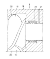
スチームモータ4は、スクリュ式スチームモータとされる。図2は、スクリュ式スチームモータ4の軸封部を示す概略図であり、一部を断面にして示している。スクリュ式スチームモータ4は、中空のケーシング18内に、互いにかみ合うようスクリュロータ19,19が設けられて構成される。スクリュロータ19,19間には蒸気が導入され、スクリュロータ19の回転が図られる。そして、このスクリュロータ19の回転により、回転動力が出力される。この間、蒸気は、スチームモータ4を通過することで、膨張して減圧される。   The steam motor 4 is a screw-type steam motor. FIG. 2 is a schematic view showing a shaft seal portion of the screw-type steam motor 4, and a part thereof is shown in cross section. The screw type steam motor 4 is configured by providing screw rotors 19 and 19 in a hollow casing 18 so as to mesh with each other. Steam is introduced between the screw rotors 19 and 19, and the screw rotor 19 is rotated. Rotational power is output by the rotation of the screw rotor 19. During this time, the steam passes through the steam motor 4 and is expanded and decompressed.

スクリュロータ19,19同士は、タイミングギア(図示省略)を介して連動回転する。このタイミングギアの潤滑油が蒸気と混合しないように、通常は、ロータ本体部20とタイミングギアとの間に排蒸口21が設けられ、この排蒸口21から蒸気を最小限の量だがケーシング18外へ漏らしながらスチームモータ4は運転される。そのために、スクリュロータ19の軸封部には、ラビリンスシールやビスコシールなどの非接触シール22が用いられる。   The screw rotors 19 and 19 rotate together through a timing gear (not shown). In order to prevent the lubricating oil of the timing gear from mixing with the steam, normally, a steam outlet 21 is provided between the rotor body 20 and the timing gear. The steam motor 4 is operated while leaking to the outside. Therefore, a non-contact seal 22 such as a labyrinth seal or a visco seal is used for the shaft seal portion of the screw rotor 19.

圧縮機5は、油潤滑式であれば、その構成を特に問わないが、ここではスクリュ式の空気圧縮機である。スクリュ式圧縮機5は、互いにかみ合って回転するスクリュロータ(図示省略)間に気体を吸入して、スクリュロータの回転により圧縮して吐出する装置である。この場合、ケーシング内で互いにかみ合って回転するスクリュロータの潤滑と、圧縮空気を作り出す空間の形成のために、ケーシング内に潤滑油が存在する。この潤滑油は、所望温度に水冷されることで、圧縮機5に発生する圧縮熱の冷却の役目も担うものである。また、通常、潤滑油だけでなく、得られる圧縮空気も水冷される。   The compressor 5 is not particularly limited as long as it is oil-lubricated, but is a screw-type air compressor here. The screw compressor 5 is a device that sucks gas between screw rotors (not shown) that rotate while meshing with each other, and compresses and discharges the gas by rotation of the screw rotor. In this case, lubricating oil is present in the casing in order to lubricate the screw rotors that rotate in mesh with each other in the casing and to form a space for generating compressed air. This lubricating oil also serves to cool the compression heat generated in the compressor 5 by being water-cooled to a desired temperature. Usually, not only the lubricating oil but also the compressed air obtained is water-cooled.

圧縮機5は、スチームモータ4により駆動される。具体的には、スクリュ式スチームモータ4のスクリュロータ19の回転駆動力を用いて、スクリュ式圧縮機5のスクリュロータが回転される。このように、圧縮機5は、スチームモータ4で駆動されるが、電動機43(図3〜図6)でも補助駆動可能とされるのがよい。   The compressor 5 is driven by the steam motor 4. Specifically, the screw rotor of the screw compressor 5 is rotated using the rotational driving force of the screw rotor 19 of the screw steam motor 4. As described above, the compressor 5 is driven by the steam motor 4, but it is preferable that the electric motor 43 (FIGS. 3 to 6) can also be auxiliary driven.

圧縮機5の潤滑油と圧縮空気とは、給水タンク7への補給水により冷却可能とされる。逆にいうと、給水タンク7への補給水は、圧縮機5の圧縮熱により加熱可能とされる。そのために、給水タンク7への補給水路8の中途には、熱交換器23が設けられる。この熱交換器23は、図1において二点鎖線で示されるように、通常、前記ユニット6の一部(より具体的には前記圧縮機5の一部)として構成される。   The lubricating oil and compressed air of the compressor 5 can be cooled by makeup water supplied to the water supply tank 7. In other words, the makeup water to the water supply tank 7 can be heated by the compression heat of the compressor 5. For this purpose, a heat exchanger 23 is provided in the supply water channel 8 to the water supply tank 7. The heat exchanger 23 is normally configured as a part of the unit 6 (more specifically, a part of the compressor 5), as indicated by a two-dot chain line in FIG.

熱交換器23は、給水タンク7への補給水が通される一方、この水と間接熱交換させて冷却しようとする圧縮機5の潤滑油と圧縮空気とが通される。そのために、本実施例の熱交換器23は、油冷却部24と空気冷却部25とを備える。また、給水タンク7への補給水は、熱交給水ポンプ26により補給水路8を流され、補給水路8の中途に設けられた熱交換器23の空気冷却部25と油冷却部24とを順に通され、給水タンク7に供給される。   The heat exchanger 23 passes makeup water to the water supply tank 7, while passing lubricating oil and compressed air of the compressor 5 to be cooled by indirect heat exchange with this water. Therefore, the heat exchanger 23 of the present embodiment includes an oil cooling unit 24 and an air cooling unit 25. Further, makeup water to the feed water tank 7 is passed through the makeup water channel 8 by the heat exchange water pump 26, and the air cooling unit 25 and the oil cooling unit 24 of the heat exchanger 23 provided in the middle of the makeup water channel 8 are sequentially supplied. And supplied to the water supply tank 7.

熱交換器23の油冷却部24には、給水タンク7への補給水が通される一方、この水と間接熱交換して冷却を図るために圧縮機5の潤滑油が通される。具体的には、熱交換器23の油冷却部24は、圧縮機5から給油路27を介して潤滑油が供給され、その潤滑油は排油路28を介して圧縮機5に戻される。このようにして、圧縮機5と熱交換器23との間で潤滑油が循環される。この際、潤滑油の循環は、圧縮機5の油分離器(図示省略)の内圧などにより自然に行われるが、場合により給油路27に循環ポンプを設けて強制的に行ってもよい。   The oil cooling section 24 of the heat exchanger 23 is supplied with makeup water to the water supply tank 7, while the lubricating oil of the compressor 5 is passed through indirect heat exchange with this water for cooling. Specifically, the oil cooling unit 24 of the heat exchanger 23 is supplied with lubricating oil from the compressor 5 through the oil supply passage 27, and the lubricating oil is returned to the compressor 5 through the oil discharge passage 28. In this way, the lubricating oil is circulated between the compressor 5 and the heat exchanger 23. At this time, the circulation of the lubricating oil is naturally performed by an internal pressure of an oil separator (not shown) of the compressor 5 or the like, but may be forcibly performed by providing a circulation pump in the oil supply passage 27 in some cases.

熱交換器23の空気冷却部25には、給水タンク7への給水が通される一方、この水と間接熱交換して冷却を図るために圧縮機5からの圧縮空気が通される。具体的には、熱交換器23の空気冷却部25は、圧縮機5から給気路29を介して圧縮空気が供給され、その空気は排気路30を介してエアドライヤ(図示省略)へ供給される。このようにして、圧縮機5からの圧縮空気は、熱交換器23にて冷却され、エアドライヤにて水分除去され、各種の圧縮空気利用機器(図示省略)へ送られる。   Water supplied to the water supply tank 7 is passed through the air cooling unit 25 of the heat exchanger 23, while compressed air from the compressor 5 is passed through indirect heat exchange with the water for cooling. Specifically, the air cooling unit 25 of the heat exchanger 23 is supplied with compressed air from the compressor 5 via an air supply path 29, and the air is supplied to an air dryer (not shown) via an exhaust path 30. The In this way, the compressed air from the compressor 5 is cooled by the heat exchanger 23, moisture is removed by the air dryer, and sent to various types of compressed air utilization equipment (not shown).

熱交換器23への給水量は、補給水路8を介した給水タンク7への給水量でもあるが、この給水量は、熱交給水ポンプ26をインバータ制御して変更可能とされる。すなわち、補給水路8に設けられた熱交給水ポンプ26は、インバータにより回転数を制御可能とされており、回転数を変更されることで熱交換器23への給水量が調整される。本実施例では、圧縮機5から熱交換器23へ供給される潤滑油を設定温度に維持するように、熱交給水ポンプ26をインバータ制御して、熱交換器23への給水量が調整される。   Although the amount of water supplied to the heat exchanger 23 is also the amount of water supplied to the water supply tank 7 via the replenishment water channel 8, this water supply amount can be changed by inverter control of the heat exchange water supply pump 26. That is, the heat exchange water supply pump 26 provided in the make-up water channel 8 can control the rotation speed by the inverter, and the amount of water supplied to the heat exchanger 23 is adjusted by changing the rotation speed. In the present embodiment, the amount of water supplied to the heat exchanger 23 is adjusted by inverter-controlling the heat exchange water pump 26 so that the lubricating oil supplied from the compressor 5 to the heat exchanger 23 is maintained at a set temperature. The

ところで、第二蒸気ヘッダ14には、その蒸気の使用負荷を把握するために、蒸気圧センサ31が設けられる。この蒸気圧センサ31により、第二蒸気ヘッダ14内の蒸気圧が監視される。従って、その蒸気圧が所定値未満であるか否かにより、蒸気負荷があるか否かを検知できる。すなわち、蒸気が使用される場合には、第二蒸気ヘッダ14内の蒸気圧が下がるので、それが所定値未満であるか否かにより、蒸気の使用負荷を検知できる。   Incidentally, the second steam header 14 is provided with a steam pressure sensor 31 in order to grasp the use load of the steam. The vapor pressure sensor 31 monitors the vapor pressure in the second vapor header 14. Therefore, whether or not there is a steam load can be detected based on whether or not the steam pressure is less than a predetermined value. That is, when the steam is used, the steam pressure in the second steam header 14 is lowered, so that the use load of the steam can be detected depending on whether or not it is less than a predetermined value.

また、圧縮機5からの圧縮空気は、圧縮空気路32(圧縮機5から熱交換器23への給気路29、熱交換器23からの排気路30、およびそれより下流路)を介して一または複数の圧縮空気利用機器(図示省略)に供給可能とされる。圧縮空気路32には、圧縮空気の使用負荷を把握するために、空気圧センサ33が設けられる。この空気圧センサ33により、圧縮空気路32内の空気圧が監視される。従って、その空気圧が設定値未満であるか否かにより、空気負荷があるか否かを検知できる。すなわち、圧縮空気が使用される場合には、圧縮空気路32内の空気圧が下がるので、それが設定値未満であるか否かにより、圧縮空気の使用負荷を検知できる。但し、圧縮空気路32の中途に中空のエアタンク(図示省略)を設け、このエアタンクに空気圧センサ33を設けて、圧縮空気の使用負荷を検知してもよい。   Compressed air from the compressor 5 passes through a compressed air passage 32 (an air supply passage 29 from the compressor 5 to the heat exchanger 23, an exhaust passage 30 from the heat exchanger 23, and a lower passage therethrough). It can be supplied to one or a plurality of compressed air utilization devices (not shown). The compressed air passage 32 is provided with an air pressure sensor 33 in order to grasp the usage load of the compressed air. The air pressure sensor 33 monitors the air pressure in the compressed air passage 32. Therefore, whether or not there is an air load can be detected based on whether or not the air pressure is less than the set value. That is, when compressed air is used, since the air pressure in the compressed air passage 32 decreases, the use load of the compressed air can be detected based on whether or not it is less than the set value. However, a hollow air tank (not shown) may be provided in the middle of the compressed air passage 32, and an air pressure sensor 33 may be provided in the air tank to detect the use load of the compressed air.

本実施例の蒸気利用システム1では、制御器34は、蒸気圧センサ31と空気圧センサ33との検出圧力を監視し、これに基づき、次に述べるように給蒸弁12の開閉または開度を制御する。   In the steam utilization system 1 of the present embodiment, the controller 34 monitors the detected pressures of the steam pressure sensor 31 and the air pressure sensor 33, and based on this, the opening / closing or opening of the steam supply valve 12 is determined as described below. Control.

制御器34は、蒸気圧センサ31の蒸気圧が所定値未満であることにより蒸気負荷があると検知し、且つ空気圧センサ33の空気圧が設定値未満であることにより空気負荷があると検知する場合には、給蒸弁12を開いてスチームモータを運転する。これにより、圧縮機5は、スチームモータ4により駆動されるが、所望により電動機により補助駆動されてもよい。   The controller 34 detects that there is a steam load when the vapor pressure of the vapor pressure sensor 31 is less than a predetermined value, and detects that there is an air load when the air pressure of the air pressure sensor 33 is less than a set value. In this case, the steam supply valve 12 is opened and the steam motor is operated. Thus, the compressor 5 is driven by the steam motor 4, but may be auxiliary driven by an electric motor if desired.

また、制御器34は、蒸気圧センサ31の蒸気圧が所定値以上であることにより蒸気負荷がないと検知し、且つ空気圧センサ33の空気圧が設定値以上であることにより空気負荷がないと検知する場合には、給蒸弁12を閉じてスチームモータ4を停止する。   Further, the controller 34 detects that there is no steam load when the vapor pressure of the vapor pressure sensor 31 is equal to or higher than a predetermined value, and detects that there is no air load when the air pressure of the air pressure sensor 33 is equal to or higher than a set value. When doing so, the steam supply valve 12 is closed and the steam motor 4 is stopped.

また、制御器34は、蒸気圧センサ31の蒸気圧が所定値未満であることにより蒸気負荷があると検知し、且つ空気圧センサ33の空気圧が設定値以上であることにより空気負荷がないと検知する場合には、給蒸弁12を閉じてスチームモータ4を停止する。この場合、第二蒸気ヘッダ14ひいては蒸気利用機器には、バイパス路16を介して蒸気が供給される。   Further, the controller 34 detects that there is a steam load when the vapor pressure of the vapor pressure sensor 31 is less than a predetermined value, and detects that there is no air load when the air pressure of the air pressure sensor 33 is equal to or greater than a set value. When doing so, the steam supply valve 12 is closed and the steam motor 4 is stopped. In this case, steam is supplied via the bypass 16 to the second steam header 14 and thus to the steam using device.

さらに、制御器34は、蒸気圧センサ31の蒸気圧が所定値以上であることにより蒸気負荷がないと検知し、且つ空気圧センサ33の空気圧が設定値未満であることにより空気負荷があると検知する場合には、電動機により圧縮機5を駆動する。この際、電動機は、前記圧縮機(スチームモータ4でも駆動可能な圧縮機)5を駆動してもよいし、前記圧縮機5とは異なる圧縮機(図示省略)を駆動してもよい。後者の場合、電動機により駆動される圧縮機からの圧縮空気は、スチームモータ4により駆動される圧縮機5からの圧縮空気と共通の圧縮空気路32またはエアタンクを介して、圧縮空気利用機器へ供給可能とされる。   Further, the controller 34 detects that there is no steam load when the vapor pressure of the vapor pressure sensor 31 is equal to or higher than a predetermined value, and detects that there is an air load when the air pressure of the air pressure sensor 33 is less than the set value. If so, the compressor 5 is driven by an electric motor. At this time, the electric motor may drive the compressor (compressor that can be driven by the steam motor 4) 5 or may drive a compressor (not shown) different from the compressor 5. In the latter case, the compressed air from the compressor driven by the electric motor is supplied to the compressed air utilization device via the compressed air passage 32 or the air tank common to the compressed air from the compressor 5 driven by the steam motor 4. It is possible.

但し、制御器34は、蒸気圧センサ31の蒸気圧が所定値以上であることにより蒸気負荷がないと検知し、且つ空気圧センサ33の空気圧が設定値未満であることにより空気負荷があると検知する場合にも、電動機に代えてまたは電動機に加えて、給蒸弁12を開いてスチームモータ4を運転してもよい。ここで、電動機に代えてスチームモータ4を運転する場合、電動機は必ずしも必要でないことになる。   However, the controller 34 detects that there is no steam load when the vapor pressure of the vapor pressure sensor 31 is equal to or higher than a predetermined value, and detects that there is an air load when the air pressure of the air pressure sensor 33 is less than the set value. In this case, the steam motor 4 may be operated by opening the steam supply valve 12 instead of or in addition to the electric motor. Here, when operating the steam motor 4 instead of the electric motor, the electric motor is not necessarily required.

なお、給蒸弁12の開閉のハンチングを防止するために、「設定値」および/または「所定値」は、それぞれ動作隙間(ディファレンシャル)を設定してもよいのはもちろんである。たとえば、圧縮空気の使用に伴い、設定下限圧力になると、給蒸弁12を開ける一方、設定上限圧力になると、給蒸弁12を閉じればよい。さらに、制御器34は、空気圧センサ33の検出圧力に基づき、空気圧を設定圧力域に維持するように、給蒸弁12の開度を制御してもよい。   In order to prevent hunting of opening / closing of the steam supply valve 12, the “set value” and / or “predetermined value” may of course each set an operation gap (differential). For example, when the set lower limit pressure is reached with the use of compressed air, the steam supply valve 12 is opened, and when the set upper limit pressure is reached, the steam supply valve 12 may be closed. Further, the controller 34 may control the opening degree of the steam supply valve 12 based on the detected pressure of the air pressure sensor 33 so as to maintain the air pressure in the set pressure range.

次に、本実施例のスチームモータ軸封部からの漏れ蒸気熱回収構造3について説明する。前述したように、スクリュ式スチームモータ4は、軸封部から排蒸口21(図2)へ蒸気を漏らしながら運転される。本実施例の漏れ蒸気熱回収構造3は、この漏れ蒸気を用いて、ボイラ2への給水、より具体的には給水タンク7への補給水の加熱を図るものである。   Next, the leak steam heat recovery structure 3 from the steam motor shaft seal portion of the present embodiment will be described. As described above, the screw steam motor 4 is operated while leaking steam from the shaft seal portion to the steam outlet 21 (FIG. 2). The leaked steam heat recovery structure 3 of the present embodiment uses this leaked steam to heat water supplied to the boiler 2, more specifically makeup water to the water supply tank 7.

具体的には、給水タンク7への補給水路8には、熱交換器23より下流部に、エゼクタ35が設けられる。エゼクタ35は、周知のとおり、一端部にノズル36が設けられ、他端部にディフューザ37が設けられ、中途部に流体の吸入口38が設けられる。そして、エゼクタ35の吸入口38は、スチームモータ4の軸封部からの漏れ蒸気の排蒸口21と、漏れ蒸気路39で接続される。   Specifically, an ejector 35 is provided downstream of the heat exchanger 23 in the replenishment water channel 8 to the water supply tank 7. As is well known, the ejector 35 is provided with a nozzle 36 at one end, a diffuser 37 at the other end, and a fluid suction port 38 in the middle. The suction port 38 of the ejector 35 is connected to the steam exhaust port 21 for the steam leaked from the shaft seal portion of the steam motor 4 through the leak steam path 39.

このような構成であるから、補給水路8に通水すれば、ノズル36からディフューザ37へ水が噴出され、スチームモータ4の軸封部からの漏れ蒸気が吸入口38へ引き込まれる。これにより、給水タンク7への補給水路8は、漏れ蒸気が混入されることで加熱され、ボイラ2への給水を予熱することができる。給水タンク7への補給水に漏れ蒸気を混入することで、給水タンク7に直接に漏れ蒸気を入れる場合と比べて、蒸気の吹き上げを抑制でき、熱の回収率を向上することができる。しかも、給水タンク7への補給水路8と、軸封部からの漏れ蒸気路39とは、少なくとも一部において配管が共通化されるので、構成の簡素化とコストの低減とを図ることができる。   With this configuration, when water is passed through the replenishment water channel 8, water is ejected from the nozzle 36 to the diffuser 37, and leaked steam from the shaft seal portion of the steam motor 4 is drawn into the suction port 38. Thereby, the replenishment water channel 8 to the water supply tank 7 is heated by mixing the leaked steam, and the water supply to the boiler 2 can be preheated. By mixing the leaked steam into the makeup water supplied to the water supply tank 7, it is possible to suppress the steam blowing up and to improve the heat recovery rate, compared to the case where the leaked steam is put directly into the water supply tank 7. In addition, since the replenishment water path 8 to the water supply tank 7 and the leak steam path 39 from the shaft seal portion have at least a part of the common piping, the configuration can be simplified and the cost can be reduced. .

ところで、スクリュ式スチームモータ4は、前述したように運転時に軸封部から蒸気を漏らすこと自体は必要であり、その蒸気の漏れが阻害されるのは好ましくない。仮に軸封部の背圧(排蒸口21の出口側の圧力)が高まれば、潤滑油と蒸気との混合が生じたり、軸封部の破損が生じたりするおそれがある。ところが、本実施例では、軸封部からの漏れ蒸気は、エゼクタ35へ吸入されるので、そのような不都合が防止される。   By the way, as described above, the screw type steam motor 4 needs to leak steam from the shaft seal portion during operation as described above, and it is not preferable that the steam leakage is inhibited. If the back pressure of the shaft seal portion (pressure on the outlet side of the steam outlet 21) increases, there is a possibility that the lubricating oil and steam are mixed, or the shaft seal portion is damaged. However, in this embodiment, the leaked steam from the shaft seal portion is sucked into the ejector 35, so that such inconvenience is prevented.

但し、補給水路8の通水量は、前述したように、熱交換器23への給水量として、流量調整される。従って、補給水路8の通水量によっては、軸封部の背圧が高まるおそれもある。そこで、図1に示すように、漏れ蒸気路39の中途に、外気への大気開放路40を設け、この大気開放路40を電磁弁41で開閉可能としている。そして、漏れ蒸気路39内の圧力が万一、設定以上の圧力になると、圧力スイッチ42により電磁弁41を開いて、漏れ蒸気を大気開放路40から直接に大気へ排出させる構成とするのがよい。この場合、圧力が低下すれば、圧力スイッチ42により、電磁弁41は再び閉じられる。   However, the flow rate of the water supply path 8 is adjusted as the amount of water supplied to the heat exchanger 23 as described above. Therefore, the back pressure of the shaft seal portion may increase depending on the amount of water passing through the replenishment water channel 8. Therefore, as shown in FIG. 1, an atmosphere release path 40 to the outside air is provided in the middle of the leak steam path 39, and the atmosphere release path 40 can be opened and closed by an electromagnetic valve 41. If the pressure in the leaking steam passage 39 becomes higher than the set pressure, the solenoid valve 41 is opened by the pressure switch 42 so that the leaking steam is discharged directly from the atmosphere opening path 40 to the atmosphere. Good. In this case, if the pressure drops, the solenoid valve 41 is closed again by the pressure switch 42.

図3は、本発明の漏れ蒸気熱回収構造3の実施例2を示す概略図である。本実施例2の漏れ蒸気熱回収構造3と、これを備える蒸気利用システム1とは、基本的に前記実施例1と同様である。そこで、以下では、両者の異なる点を中心に説明し、対応する箇所には同一の符号を付して説明する。なお、同様の理由から、図3では、図1と同様の箇所を省略して示している。   FIG. 3 is a schematic view showing Example 2 of the leaked steam heat recovery structure 3 of the present invention. The leakage steam heat recovery structure 3 of the second embodiment and the steam utilization system 1 including the same are basically the same as those of the first embodiment. Therefore, in the following description, the differences between the two will be mainly described, and corresponding portions will be described with the same reference numerals. For the same reason, in FIG. 3, the same parts as in FIG. 1 are omitted.

前記実施例1では、給水タンク7への補給水路8の中途にエゼクタ35を設け、このエゼクタ35の吸入口38に漏れ蒸気路39を接続したが、本実施例2では、漏れ蒸気路39は、給水タンク7内に直接に配管される。これにより、スチームモータ4の軸封部からの漏れ蒸気は、ボイラ2の給水タンク7の貯留水内に直接に吹き込まれる。この場合、給水タンク7への補給水路8は、漏れ蒸気路39とは別に、給水タンク7に配管される。   In the first embodiment, an ejector 35 is provided in the middle of the replenishment water path 8 to the water supply tank 7, and a leak steam path 39 is connected to the suction port 38 of the ejector 35. In the second embodiment, the leak steam path 39 is The pipe is directly piped into the water supply tank 7. Thereby, the leaked steam from the shaft seal portion of the steam motor 4 is directly blown into the stored water in the water supply tank 7 of the boiler 2. In this case, the replenishment water passage 8 to the water supply tank 7 is piped to the water supply tank 7 separately from the leakage steam passage 39.

本実施例2の構成は、漏れ蒸気の圧力との関係で、スチームモータ4の軸封部への背圧が懸念されない場合に用いられる。前記実施例1と比較して、エゼクタ35がなく構成が簡易である。   The configuration of the second embodiment is used when the back pressure to the shaft seal portion of the steam motor 4 is not a concern due to the pressure of the leaking steam. Compared with the first embodiment, there is no ejector 35 and the configuration is simple.

ところで、本実施例2では、圧縮機5を駆動する原動機として、スクリュ式スチームモータ4の他に、さらに電動機43を備える。図示例では、電動機43として両軸モータが用いられ、電動機43を貫通するよう設けられる回転軸は、一端部にスチームモータ4の出力軸が接続され、他端部に圧縮機5の入力軸が接続される。これにより、圧縮機5は、スチームモータ4により駆動可能とされると共に、それに代えてまたはそれに加えて、電動機43により駆動可能とされる。その他の構成および制御は、前記実施例1と同様のため、説明は省略する。   By the way, in the second embodiment, an electric motor 43 is further provided in addition to the screw-type steam motor 4 as a prime mover for driving the compressor 5. In the illustrated example, a double-axis motor is used as the electric motor 43, and the rotary shaft provided so as to penetrate the electric motor 43 is connected to the output shaft of the steam motor 4 at one end and the input shaft of the compressor 5 to the other end. Connected. Thus, the compressor 5 can be driven by the steam motor 4 and can be driven by the electric motor 43 instead of or in addition to the steam motor 4. Other configurations and controls are the same as those in the first embodiment, and a description thereof will be omitted.

図4は、本発明の漏れ蒸気熱回収構造3の実施例3を示す概略図である。本実施例3の漏れ蒸気熱回収構造3と、これを備える蒸気利用システム1とは、基本的に前記実施例2と同様である。そこで、以下では、両者の異なる点を中心に説明し、対応する箇所には同一の符号を付して説明する。   FIG. 4 is a schematic view showing Example 3 of the leaked steam heat recovery structure 3 of the present invention. The leaked steam heat recovery structure 3 of the third embodiment and the steam utilization system 1 including the same are basically the same as those of the second embodiment. Therefore, in the following description, the differences between the two will be mainly described, and corresponding portions will be described with the same reference numerals.

本実施例3では、給水タンク7への補給水路8に熱交換器44が設けられる。この熱交換器44には、給水タンク7への補給水が通されると共に、スチームモータ4の軸封部からの漏れ蒸気が通される。これにより、給水タンク7への補給水と、スチームモータ4の軸封部からの漏れ蒸気とを間接熱交換して、漏れ蒸気により給水タンク7への補給水の加熱を図ることができる。熱交換後の漏れ蒸気やその凝縮水は、給水タンク7に供給されてもよい。その他の構成および制御は、前記実施例2と同様のため、説明は省略する。ところで、熱交換器44を給水タンク7内に設置して、スチームモータ4の軸封部からの漏れ蒸気で、給水タンク7内の貯留水を加熱するよう構成してもよい。   In the third embodiment, a heat exchanger 44 is provided in the replenishment water channel 8 to the water supply tank 7. The heat exchanger 44 is supplied with makeup water to the water supply tank 7 and also leaked steam from the shaft seal portion of the steam motor 4. As a result, the replenishment water to the water supply tank 7 and the leaked steam from the shaft seal portion of the steam motor 4 can be indirectly heat-exchanged, and the water supply to the water supply tank 7 can be heated by the leaked steam. The leaked steam and its condensed water after heat exchange may be supplied to the water supply tank 7. Other configurations and controls are the same as those in the second embodiment, and a description thereof will be omitted. By the way, the heat exchanger 44 may be installed in the water supply tank 7, and the stored water in the water supply tank 7 may be heated by the leaked steam from the shaft seal portion of the steam motor 4.

図5は、本発明の漏れ蒸気熱回収構造3の実施例4を示す概略図である。本実施例4の漏れ蒸気熱回収構造3と、これを備える蒸気利用システム1とは、基本的に前記実施例2と同様である。そこで、以下では、両者の異なる点を中心に説明し、対応する箇所には同一の符号を付して説明する。   FIG. 5 is a schematic view showing Example 4 of the leaked steam heat recovery structure 3 of the present invention. The leaked steam heat recovery structure 3 of the fourth embodiment and the steam utilization system 1 including the same are basically the same as those of the second embodiment. Therefore, in the following description, the differences between the two will be mainly described, and corresponding portions will be described with the same reference numerals.

本実施例4では、給水タンク7への補給水路8の中途に、スチームモータ4からの漏れ蒸気路39が接続される。すなわち、前記実施例1において、補給水路8と漏れ蒸気路39との接続部にエゼクタ35を設置するのに代えて、補給水路8と漏れ蒸気路39とを単に合流させた構成である。この場合も、補給水路8の通水により、漏れ蒸気を補給水路8に引き込むことができる。   In the fourth embodiment, a leakage steam path 39 from the steam motor 4 is connected in the middle of the supply water path 8 to the water supply tank 7. That is, in the first embodiment, instead of installing the ejector 35 at the connection portion between the replenishment water passage 8 and the leak steam passage 39, the replenishment water passage 8 and the leak steam passage 39 are simply joined together. Also in this case, the leaked steam can be drawn into the replenishment water channel 8 by passing through the replenishment water channel 8.

また、前記実施例1と同様に、給水タンク7への補給水に漏れ蒸気を混入することで、給水タンク7に直接に漏れ蒸気を入れる場合と比べて、蒸気の吹き上げを抑制でき、熱の回収率を向上することができる。しかも、給水タンク7への補給水路8と、軸封部からの漏れ蒸気路39とは、少なくとも一部において配管が共通化されるので、構成の簡素化とコストの低減とを図ることができる。   Further, as in the first embodiment, by mixing leaked steam into the makeup water supplied to the water supply tank 7, it is possible to suppress the steam blow-up compared to the case where the leaked steam is put directly into the water supply tank 7, and the heat The recovery rate can be improved. In addition, since the replenishment water path 8 to the water supply tank 7 and the leak steam path 39 from the shaft seal portion have at least a part of the common piping, the configuration can be simplified and the cost can be reduced. .

本実施例4においても、前記実施例1と同様に、所望により漏れ蒸気路39に電磁弁41付きの大気開放路40と圧力スイッチ42とを設け、漏れ蒸気を大気に開放可能としてもよい。その他の構成および制御は、前記実施例2と同様のため、説明は省略する。   Also in the fourth embodiment, similarly to the first embodiment, if necessary, the leakage steam path 39 may be provided with an atmosphere opening path 40 with a solenoid valve 41 and a pressure switch 42 so that the leakage steam can be opened to the atmosphere. Other configurations and controls are the same as those in the second embodiment, and a description thereof will be omitted.

図6は、本発明の漏れ蒸気熱回収構造3の実施例5を示す概略図である。本実施例5の漏れ蒸気熱回収構造3と、これを備える蒸気利用システム1とは、基本的に前記実施例4と同様である。そこで、以下では、両者の異なる点を中心に説明し、対応する箇所には同一の符号を付して説明する。   FIG. 6 is a schematic view showing Example 5 of the leaked steam heat recovery structure 3 of the present invention. The leakage steam heat recovery structure 3 of the fifth embodiment and the steam utilization system 1 including the same are basically the same as those of the fourth embodiment. Therefore, in the following description, the differences between the two will be mainly described, and corresponding portions will be described with the same reference numerals.

本実施例5では、補給水路8には、漏れ蒸気路39との合流部よりも下流部に、ポンプ45が設けられている。このポンプ45の吸込みにより、スチームモータ4の軸封部からの漏れ蒸気は、補給水路8に円滑に吸入される。但し、このポンプ45は、漏れ蒸気路39に設置してもよい。その場合、スチームモータ4の軸封部からの漏れ蒸気は、補給水路8の通水に押し込まれる。その他の構成および制御は、前記実施例4と同様のため、説明は省略する。   In the fifth embodiment, the replenishment water channel 8 is provided with a pump 45 downstream from the junction with the leakage steam channel 39. Due to the suction of the pump 45, the leaked steam from the shaft seal portion of the steam motor 4 is smoothly sucked into the supply water channel 8. However, the pump 45 may be installed in the leak steam path 39. In that case, the leaked steam from the shaft seal portion of the steam motor 4 is pushed into the water flow of the replenishment water channel 8. Other configurations and controls are the same as those in the fourth embodiment, and thus description thereof is omitted.

本発明のスチームモータ軸封部からの漏れ蒸気熱回収構造3と、これが適用される蒸気利用システム1とは、前記各実施例の構成に限らず適宜変更可能である。特に、スチームモータ4の軸封部からの漏れ蒸気を利用する構成であれば、その利用箇所および利用方法は、前記各実施例に限定されない。たとえば、前記各実施例では、ボイラ2への給水の予熱に用いたが、ボイラ2以外で温水を利用してもよい。   The steam heat recovery structure 3 leaking from the shaft seal portion of the present invention and the steam utilization system 1 to which the steam heat recovery structure 3 is applied are not limited to the configurations of the above-described embodiments, and can be changed as appropriate. In particular, as long as the steam that leaks from the shaft seal portion of the steam motor 4 is used, the use location and the use method are not limited to the above embodiments. For example, in each said Example, although used for the preheating of the water supply to the boiler 2, you may utilize warm water other than the boiler 2. FIG.

また、図1では、給水タンク7への補給水路8には熱交給水ポンプ26を設置したが、原水圧がある場合には、熱交給水ポンプ26の設置を省略してもよい。この場合、熱交給水ポンプ26に代えて電動弁を設置し、この電動弁の開度を調整することで、熱交換器23ひいては給水タンク7への給水量を調整してもよい。   In FIG. 1, the heat exchange water pump 26 is installed in the replenishment water channel 8 to the water supply tank 7. However, when there is a raw water pressure, the installation of the heat exchange water pump 26 may be omitted. In this case, an electric valve may be installed in place of the heat exchange water supply pump 26, and the amount of water supplied to the heat exchanger 23 and thus the water supply tank 7 may be adjusted by adjusting the opening of the electric valve.

さらに、前記実施例では、熱交換器23では、油潤滑式圧縮機5の潤滑油と圧縮空気の双方を冷却する構成としたが、場合により、潤滑油と圧縮空気とのいずれか一方のみを冷却する構成としてもよい。   Furthermore, in the said Example, although the heat exchanger 23 was set as the structure which cools both the lubricating oil and compressed air of the oil lubricated compressor 5, depending on the case, only one of lubricating oil and compressed air is used. It is good also as a structure to cool.

本発明の漏れ蒸気熱回収構造の実施例1が適用された蒸気利用システムの一例を示す概略図である。It is the schematic which shows an example of the vapor | steam utilization system to which Example 1 of the leak steam heat recovery structure of this invention was applied. スクリュ式スチームモータの軸封部を示す概略図であり、一部を断面にして示している。It is the schematic which shows the shaft seal part of a screw type steam motor, and has shown it by making a part into a cross section. 本発明の漏れ蒸気熱回収構造の実施例2を示す概略図である。It is the schematic which shows Example 2 of the leak steam heat recovery structure of this invention. 本発明の漏れ蒸気熱回収構造の実施例3を示す概略図である。It is the schematic which shows Example 3 of the leak steam heat recovery structure of this invention. 本発明の漏れ蒸気熱回収構造の実施例4を示す概略図である。It is the schematic which shows Example 4 of the leak steam heat recovery structure of this invention. 本発明の漏れ蒸気熱回収構造の実施例5を示す概略図である。It is the schematic which shows Example 5 of the leak steam heat recovery structure of this invention.

符号の説明Explanation of symbols

1 蒸気利用システム
2 ボイラ
3 漏れ蒸気熱回収構造
4 スチームモータ
5 圧縮機
7 給水タンク
8 補給水路
21 排蒸口
22 非接触シール
23 熱交換器
35 エゼクタ
36 ノズル
37 ディフューザ
38 吸入口
39 漏れ蒸気路
40 大気開放路
41 電磁弁
42 圧力スイッチ
44 熱交換器
45 ポンプ
DESCRIPTION OF SYMBOLS 1 Steam utilization system 2 Boiler 3 Leakage steam heat recovery structure 4 Steam motor 5 Compressor 7 Water supply tank 8 Supply channel 21 Steam outlet 22 Non-contact seal 23 Heat exchanger 35 Ejector 36 Nozzle 37 Diffuser 38 Suction port 39 Leakage steam path 40 Open air path 41 Solenoid valve 42 Pressure switch 44 Heat exchanger 45 Pump

Claims (8)

蒸気を用いて動力を起こすスクリュ式スチームモータの軸封部から漏れる蒸気を、その漏れ蒸気の熱を利用したい箇所へ供給する
ことを特徴とするスチームモータ軸封部からの漏れ蒸気熱回収構造。
Steam leakage recovery structure from a steam motor shaft seal, which supplies steam leaking from the shaft seal of a screw-type steam motor that generates power using steam to the location where the heat of the leaked steam is to be used.
ボイラへの給水タンクの貯留水内に、前記スチームモータの軸封部からの漏れ蒸気を供給する
ことを特徴とする請求項1に記載のスチームモータ軸封部からの漏れ蒸気熱回収構造。
The leak steam heat recovery structure from the steam motor shaft seal according to claim 1, wherein leak steam from the shaft seal of the steam motor is supplied into the water stored in the water supply tank to the boiler.
ボイラへの給水タンクまたはこの給水タンクへの補給水路に、間接熱交換器を設け、
この間接熱交換器に前記スチームモータの軸封部からの漏れ蒸気を通して、前記給水タンクの水または前記補給水路の水を加熱する
ことを特徴とする請求項1に記載のスチームモータ軸封部からの漏れ蒸気熱回収構造。
An indirect heat exchanger is installed in the water supply tank to the boiler or the supply water channel to this water supply tank.
The steam of the water supply tank or the water of the replenishment water channel is heated through the steam leaked from the shaft seal of the steam motor through the indirect heat exchanger. Leakage steam heat recovery structure.
ボイラの給水タンクへの補給水路内に、前記スチームモータの軸封部からの漏れ蒸気を供給する
ことを特徴とする請求項1に記載のスチームモータ軸封部からの漏れ蒸気熱回収構造。
The leak steam heat recovery structure from the steam motor shaft seal according to claim 1, wherein the steam leaked from the shaft seal of the steam motor is supplied into a supply water channel to a water supply tank of the boiler.
前記補給水路の中途に、エゼクタを設け、
前記補給水路に通水して、前記エゼクタにより、前記スチームモータの軸封部からの漏れ蒸気を前記補給水路内へ吸入する
ことを特徴とする請求項4に記載のスチームモータ軸封部からの漏れ蒸気熱回収構造。
In the middle of the makeup channel, an ejector is provided,
5. The steam motor shaft seal according to claim 4, wherein water is passed through the makeup water channel, and the ejector sucks leaked steam from the shaft seal portion of the steam motor into the makeup water channel. Leaky steam heat recovery structure.
前記スチームモータの軸封部からの漏れ蒸気を前記補給水路へ供給する漏れ蒸気路は、この漏れ蒸気路内の圧力が設定以上になると大気に開放される
ことを特徴とする請求項4または請求項5に記載のスチームモータ軸封部からの漏れ蒸気熱回収構造。
5. The leak steam path for supplying the steam leaked from the shaft seal portion of the steam motor to the makeup water path is opened to the atmosphere when the pressure in the leak steam path exceeds a set value. Item 6. A structure for recovering steam heat leaked from a steam motor shaft seal according to Item 5.
前記スチームモータの軸封部からの漏れ蒸気を前記補給水路へ供給する漏れ蒸気路にポンプを設けて漏れ蒸気を前記補給水路へ吐出するか、前記補給水路の中途にポンプを設けて漏れ蒸気を前記補給水路へ吸入する
ことを特徴とする請求項4に記載のスチームモータ軸封部からの漏れ蒸気熱回収構造。
A pump is provided in the leakage steam path for supplying the steam leaked from the shaft seal portion of the steam motor to the makeup water path and the leakage steam is discharged to the makeup water path, or a pump is provided in the middle of the makeup water path to remove the leakage steam. The leak steam heat recovery structure from the steam motor shaft seal according to claim 4, wherein the steam is sucked into the makeup water channel.
前記補給水路の水は、前記スチームモータにより駆動される油潤滑式の圧縮機からの被冷却流体としての圧縮空気および/または潤滑油を冷却後、前記スチームモータの軸封部からの漏れ蒸気で加熱されて、前記給水タンクへ供給される
ことを特徴とする請求項3〜7のいずれか1項に記載のスチームモータ軸封部からの漏れ蒸気熱回収構造。
The water in the replenishment channel is the leaked steam from the shaft seal portion of the steam motor after cooling the compressed air and / or lubricating oil as the fluid to be cooled from the oil lubricated compressor driven by the steam motor. It is heated and supplied to the water supply tank. The leak steam heat recovery structure from the steam motor shaft seal according to any one of claims 3 to 7.
JP2008212124A 2008-08-20 2008-08-20 Leakage steam heat recovery structure from steam motor shaft seal Active JP5256932B2 (en)

Priority Applications (1)

Application Number Priority Date Filing Date Title
JP2008212124A JP5256932B2 (en) 2008-08-20 2008-08-20 Leakage steam heat recovery structure from steam motor shaft seal

Applications Claiming Priority (1)

Application Number Priority Date Filing Date Title
JP2008212124A JP5256932B2 (en) 2008-08-20 2008-08-20 Leakage steam heat recovery structure from steam motor shaft seal

Publications (2)

Publication Number Publication Date
JP2010048450A true JP2010048450A (en) 2010-03-04
JP5256932B2 JP5256932B2 (en) 2013-08-07

Family

ID=42065682

Family Applications (1)

Application Number Title Priority Date Filing Date
JP2008212124A Active JP5256932B2 (en) 2008-08-20 2008-08-20 Leakage steam heat recovery structure from steam motor shaft seal

Country Status (1)

Country Link
JP (1) JP5256932B2 (en)

Cited By (2)

* Cited by examiner, † Cited by third party
Publication number Priority date Publication date Assignee Title
CN103453797A (en) * 2012-06-04 2013-12-18 上海瀚显空调节能技术有限公司 Air compressor heat recovery unit with intelligent anti-leakage function
US20140150736A1 (en) * 2011-08-12 2014-06-05 Victor Tokuhan Co., Ltd. Heat recovery apparatus and heat recovery system

Citations (5)

* Cited by examiner, † Cited by third party
Publication number Priority date Publication date Assignee Title
JPS5815804U (en) * 1981-07-16 1983-01-31 株式会社東芝 Valve gland leakage steam recovery device
JPH0449710U (en) * 1990-08-29 1992-04-27
JPH0598902A (en) * 1991-10-09 1993-04-20 Mayekawa Mfg Co Ltd Enclosed type power generating device by expansion engine and rankine power generating system using it
JP2004036535A (en) * 2002-07-04 2004-02-05 Kansai Electric Power Co Inc:The Power plant main machine exhaust heat recovery system
JP2008157511A (en) * 2006-12-22 2008-07-10 Chugoku Electric Power Co Inc:The Bearing cooling water heat recovery device

Patent Citations (5)

* Cited by examiner, † Cited by third party
Publication number Priority date Publication date Assignee Title
JPS5815804U (en) * 1981-07-16 1983-01-31 株式会社東芝 Valve gland leakage steam recovery device
JPH0449710U (en) * 1990-08-29 1992-04-27
JPH0598902A (en) * 1991-10-09 1993-04-20 Mayekawa Mfg Co Ltd Enclosed type power generating device by expansion engine and rankine power generating system using it
JP2004036535A (en) * 2002-07-04 2004-02-05 Kansai Electric Power Co Inc:The Power plant main machine exhaust heat recovery system
JP2008157511A (en) * 2006-12-22 2008-07-10 Chugoku Electric Power Co Inc:The Bearing cooling water heat recovery device

Cited By (4)

* Cited by examiner, † Cited by third party
Publication number Priority date Publication date Assignee Title
US20140150736A1 (en) * 2011-08-12 2014-06-05 Victor Tokuhan Co., Ltd. Heat recovery apparatus and heat recovery system
US9664379B2 (en) 2011-08-12 2017-05-30 Victor Tokuhan Co., Ltd. Heat recovery apparatus and heat recovery system
CN103453797A (en) * 2012-06-04 2013-12-18 上海瀚显空调节能技术有限公司 Air compressor heat recovery unit with intelligent anti-leakage function
CN103453797B (en) * 2012-06-04 2015-09-09 上海瀚显空调节能技术有限公司 A kind of air compressor machine recuperation of heat unit with Intelligent anti-leakage function

Also Published As

Publication number Publication date
JP5256932B2 (en) 2013-08-07

Similar Documents

Publication Publication Date Title
US10495098B2 (en) Systems and methods for balancing thrust loads in a heat engine system
JP6194274B2 (en) Waste heat recovery system and waste heat recovery method
JP5598724B2 (en) Compression heat recovery system
JP4997333B2 (en) Method and apparatus for starting a refrigerant system without preheating oil
JP5223526B2 (en) Boiler water supply system
KR101325350B1 (en) Power generating apparatus
JP6060040B2 (en) Waste heat recovery device and operation control method of waste heat recovery device
KR101668363B1 (en) Energy system
JP2010174848A (en) Waste heat regeneration system
WO2009147873A1 (en) Steam system
JP5256932B2 (en) Leakage steam heat recovery structure from steam motor shaft seal
JP5639534B2 (en) Binary power generator
KR101707744B1 (en) Compressing device
KR102309815B1 (en) Leak fluid regenerative turbo expander
JP4353311B1 (en) Steam system
JP6595008B2 (en) Gas compressor and gas compressor system
JP6511297B2 (en) Power generator
JP5671442B2 (en) Thermal energy utilization apparatus and operation method thereof
JP5653320B2 (en) Waste heat regeneration system
JP2007010257A (en) Heat pump device
JP6321568B2 (en) Power generator
JP2009052489A (en) Steam system
JP6403282B2 (en) Thermal energy recovery device
JP2007147179A (en) Refrigerating cycle device and its operation method
KR20130004188A (en) Hot water boiler using turbo fan

Legal Events

Date Code Title Description
A621 Written request for application examination

Free format text: JAPANESE INTERMEDIATE CODE: A621

Effective date: 20110525

A131 Notification of reasons for refusal

Free format text: JAPANESE INTERMEDIATE CODE: A131

Effective date: 20121218

A521 Request for written amendment filed

Free format text: JAPANESE INTERMEDIATE CODE: A523

Effective date: 20130121

TRDD Decision of grant or rejection written
A01 Written decision to grant a patent or to grant a registration (utility model)

Free format text: JAPANESE INTERMEDIATE CODE: A01

Effective date: 20130326

A61 First payment of annual fees (during grant procedure)

Free format text: JAPANESE INTERMEDIATE CODE: A61

Effective date: 20130408

FPAY Renewal fee payment (event date is renewal date of database)

Free format text: PAYMENT UNTIL: 20160502

Year of fee payment: 3

R150 Certificate of patent or registration of utility model

Free format text: JAPANESE INTERMEDIATE CODE: R150

Ref document number: 5256932

Country of ref document: JP

Free format text: JAPANESE INTERMEDIATE CODE: R150

R250 Receipt of annual fees

Free format text: JAPANESE INTERMEDIATE CODE: R250

R250 Receipt of annual fees

Free format text: JAPANESE INTERMEDIATE CODE: R250

R250 Receipt of annual fees

Free format text: JAPANESE INTERMEDIATE CODE: R250

R250 Receipt of annual fees

Free format text: JAPANESE INTERMEDIATE CODE: R250

R250 Receipt of annual fees

Free format text: JAPANESE INTERMEDIATE CODE: R250

R250 Receipt of annual fees

Free format text: JAPANESE INTERMEDIATE CODE: R250

R250 Receipt of annual fees

Free format text: JAPANESE INTERMEDIATE CODE: R250

R250 Receipt of annual fees

Free format text: JAPANESE INTERMEDIATE CODE: R250