JP2010048386A - Rotary damper - Google Patents
Rotary damper Download PDFInfo
- Publication number
- JP2010048386A JP2010048386A JP2008214989A JP2008214989A JP2010048386A JP 2010048386 A JP2010048386 A JP 2010048386A JP 2008214989 A JP2008214989 A JP 2008214989A JP 2008214989 A JP2008214989 A JP 2008214989A JP 2010048386 A JP2010048386 A JP 2010048386A
- Authority
- JP
- Japan
- Prior art keywords
- viscous liquid
- pressing means
- chambers
- main body
- body case
- Prior art date
- Legal status (The legal status is an assumption and is not a legal conclusion. Google has not performed a legal analysis and makes no representation as to the accuracy of the status listed.)
- Granted
Links
- 239000007788 liquid Substances 0.000 claims description 79
- 239000012530 fluid Substances 0.000 abstract description 6
- 238000010586 diagram Methods 0.000 description 5
- 238000005192 partition Methods 0.000 description 4
- 230000002093 peripheral effect Effects 0.000 description 2
- 238000010992 reflux Methods 0.000 description 2
- 230000015572 biosynthetic process Effects 0.000 description 1
Images


Abstract
Description
本発明は、概してロータリーダンパに関し、より詳細には、一方向性ロータリーダンパに関する。 The present invention relates generally to rotary dampers, and more particularly to unidirectional rotary dampers.
従来、本体ケース内に設けられる軸部材と、前記本体ケース内に充填される粘性液体と、前記本体ケース内に設けられ、前記軸部材を中心として回転することによって前記粘性液体を押圧する複数の押圧手段とを備えるロータリーダンパが知られている。この種のロータリーダンパは、各押圧手段が粘性液体を押圧することによって生じる粘性液体の抵抗を利用して制御対象物の動作速度を減速させるものである。また、この種のロータリーダンパの中には、各押圧手段が一方向に回転するときに生じる粘性液体の抵抗と、各押圧手段が逆方向に回転するときに生じる粘性液体の抵抗に差がある一方向性のものがある。 Conventionally, a shaft member provided in the main body case, a viscous liquid filled in the main body case, and a plurality of pressure members provided in the main body case that press the viscous liquid by rotating around the shaft member. A rotary damper having a pressing means is known. This type of rotary damper decelerates the operating speed of the controlled object using the resistance of the viscous liquid generated by each pressing means pressing the viscous liquid. Further, in this type of rotary damper, there is a difference between the resistance of the viscous liquid generated when each pressing means rotates in one direction and the resistance of the viscous liquid generated when each pressing means rotates in the opposite direction. Some are unidirectional.
一方向性ロータリーダンパは、各押圧手段が軸部材を中心として一方向に回転して粘性液体を押圧したときに生じる粘性液体の抵抗よりも、各押圧手段が軸部材を中心として逆方向に回転して粘性液体を押圧したときに生じる粘性液体の抵抗を小さくさせる制御機構を備えている。例えば、下記特許文献1には、押圧手段として機能する2つのベーンが軸部材として機能する回転軸を中心として一方向に回転したときに粘性液体が通過できないように閉鎖され、各ベーンが回転軸を中心として逆方向に回転したときに粘性液体が通過できるように開放される還流溝と、該還流溝の開閉を行う突起とを備えて構成される制御機構が記載されている。
The unidirectional rotary damper is configured so that each pressing means rotates in the opposite direction around the shaft member rather than the resistance of the viscous liquid generated when each pressing means rotates in one direction around the shaft member and presses the viscous liquid. And a control mechanism for reducing the resistance of the viscous liquid generated when the viscous liquid is pressed. For example, in
一方向性ロータリーダンパでは、一般に、各押圧手段が一方向に回転したときに、各押圧手段によって押圧された粘性液体が流入する複数の室の内圧が均一になるように設計される。しかしながら、実際には、これらの室の内圧に差が生じることがある。このような現象は、例えば、本体ケースと各押圧手段との間に形成される隙間の大きさにばらつきがある場合に生じる。このような現象が生じた場合には、制動特性にばらつきが生じたり、軸部材の位置がずれて、軸部材がOリングなどのシール部材を過剰に圧迫し、粘性液体の漏れを引き起こしたりする問題が生じる。
本発明が解決しようとする課題は、本体ケース内において、様々な箇所に形成される隙間の大きさにばらつきがある場合でも、各押圧手段が一方向に回転したときに、各押圧手段によって押圧された粘性液体が流入する複数の室の内圧を均一することができるロータリーダンパを提供することである。 The problem to be solved by the present invention is that, even when there are variations in the sizes of the gaps formed at various locations in the main body case, when the respective pressing means are rotated in one direction, they are pressed by the respective pressing means. It is an object of the present invention to provide a rotary damper capable of uniforming the internal pressure of a plurality of chambers into which a viscous liquid is introduced.
本発明は、上記課題を解決するため、以下のロータリーダンパを提供する。
1.本体ケース(1)内に設けられる軸部材(3)と、前記本体ケース(1)内に充填される粘性液体と、前記本体ケース(1)内に設けられ、前記軸部材(3)を中心として回転することによって前記粘性液体を押圧する複数の押圧手段(4a,4b又は5a,5b)と、各押圧手段(4a,4b又は5a,5b)が一方向に回転して前記粘性液体を押圧したときに生じる前記粘性液体の抵抗よりも、各押圧手段(4a,4b又は5a,5b)が逆方向に回転して前記粘性液体を押圧したときに生じる前記粘性液体の抵抗を小さくさせる制御機構とを備えるロータリーダンパであって、
各押圧手段(4a,4b又は5a,5b)が一方向に回転したときに、各押圧手段(4a,4b又は5a,5b)によって押圧される前記粘性液体を収容する複数の室(6a,6b)間で前記粘性液体の流通を可能にする流路は設けずに、そのときに、各押圧手段(4a,4b又は5a,5b)によって押圧された前記粘性液体が流入する複数の室(7a,7b)間でのみ前記粘性液体の流通を可能にする流路(10)を設けたことを特徴とするロータリーダンパ。
2.前記本体ケース(1)の開口部を閉塞し、各押圧手段(4a,4b又は5a,5b)が回転するときに、各押圧手段(4a,4b又は5a,5b)が摺接する底面を有する蓋部材(2)を備え、前記流路(10)が、前記本体ケース(1)、前記軸部材(3)又は前記蓋部材(2)に設けられていることを特徴とする前記1記載のロータリーダンパ。
3.前記本体ケース(1)の開口部を閉塞する蓋部材(2)と、各押圧手段(4a,4b又は5a,5b)と前記蓋部材(2)との間に設けられ、各押圧手段(4a,4b又は5a,5b)が回転するときに、各押圧手段(4a,4b又は5a,5b)が摺接する底面を有する中間部材(11)とを備え、前記流路(10)が、前記中間部材(11)に設けられていることを特徴とする前記1記載のロータリーダンパ。
4.前記軸部材(3)が中空であり、前記流路(10)が、前記軸部材(3)の中空部分(3a)を迂回した態様で設けられていることを特徴とする前記1記載のロータリーダンパ。
In order to solve the above problems, the present invention provides the following rotary damper.
1. A shaft member (3) provided in the main body case (1), a viscous liquid filled in the main body case (1), and provided in the main body case (1), with the shaft member (3) as a center. A plurality of pressing means (4a, 4b or 5a, 5b) that press the viscous liquid by rotating as shown in FIG. 5 and each pressing means (4a, 4b or 5a, 5b) rotates in one direction to press the viscous liquid. Control mechanism for reducing the resistance of the viscous liquid generated when each of the pressing means (4a, 4b or 5a, 5b) rotates in the opposite direction and presses the viscous liquid, rather than the resistance of the viscous liquid generated when A rotary damper comprising
When each pressing means (4a, 4b or 5a, 5b) rotates in one direction, a plurality of chambers (6a, 6b) containing the viscous liquid pressed by each pressing means (4a, 4b or 5a, 5b) ) Between the plurality of chambers (7a) into which the viscous liquid pressed by the pressing means (4a, 4b or 5a, 5b) flows at that time. , 7b), provided with a flow path (10) that allows the viscous liquid to flow therethrough.
2. A lid having a bottom surface that closes the opening of the main body case (1) and is in sliding contact with each pressing means (4a, 4b or 5a, 5b) when each pressing means (4a, 4b or 5a, 5b) rotates. The rotary according to
3. The lid member (2) for closing the opening of the main body case (1), the pressing means (4a, 4b or 5a, 5b) and the lid member (2) are provided between the pressing means (4a). , 4b or 5a, 5b) and an intermediate member (11) having a bottom surface with which each pressing means (4a, 4b or 5a, 5b) is slidably contacted, and the flow path (10) includes the
4). 2. The rotary according to 1, wherein the shaft member (3) is hollow, and the flow path (10) is provided so as to bypass the hollow portion (3 a) of the shaft member (3). damper.
本発明によれば、各押圧手段(4a,4b又は5a,5b)が一方向に回転したときに、各押圧手段(4a,4b又は5a,5b)によって押圧された粘性液体が流入する複数の室(7a,7b)間でのみ粘性液体の流通を可能にする流路(10)が設けられているため、各押圧手段(4a,4b又は5a,5b)が一方向に回転したときに、これらの室(7a,7b)の内圧を均一にすることが可能になる。したがって、本体ケース(1)内において、様々な箇所に形成される隙間の大きさにばらつきがある場合でも、制動特性のばらつきを抑制することができ、また、軸部材(3)の位置がずれて軸部材(3)がシール部材(12)を過剰に圧迫すること及びそれにより粘性液体の漏れが生じることを防止することもできる。
また、本発明によれば、各押圧手段(4a,4b又は5a,5b)が一方向に回転したときに、各押圧手段(4a,4b又は5a,5b)によって押圧される粘性液体を収容する複数の室(6a,6b)間で粘性液体の流通を可能にする流路が設けられていないので、構造が簡素であり、また、流路を形成することによる構成部品の強度の低下も最小限に抑えることができる。
According to the present invention, when each pressing means (4a, 4b or 5a, 5b) rotates in one direction, a plurality of viscous liquids pressed by each pressing means (4a, 4b or 5a, 5b) flow in. Since the flow path (10) that enables the flow of the viscous liquid only between the chambers (7a, 7b) is provided, when each pressing means (4a, 4b or 5a, 5b) rotates in one direction, It becomes possible to make the internal pressure of these chambers (7a, 7b) uniform. Therefore, even when there are variations in the sizes of the gaps formed at various locations in the body case (1), variations in braking characteristics can be suppressed, and the position of the shaft member (3) is shifted. Thus, it is possible to prevent the shaft member (3) from excessively pressing the seal member (12) and thereby causing leakage of viscous liquid.
Moreover, according to this invention, when each press means (4a, 4b or 5a, 5b) rotates to one direction, the viscous liquid pressed by each press means (4a, 4b or 5a, 5b) is accommodated. Since there is no flow path that allows the viscous liquid to flow between the plurality of chambers (6a, 6b), the structure is simple, and the decrease in the strength of the components due to the formation of the flow path is also minimal. To the limit.
本発明の一実施形態では、ロータリーダンパは、本体ケース1、蓋部材2、軸部材3、粘性液体、押圧手段、制御機構及び流路10を有して構成される。
In one embodiment of the present invention, the rotary damper includes a
本体ケース1は、ケーシング又はハウジングとも呼ばれるものであり、図1〜図12に示されている。本体ケース1は、典型的には、一端が開口し、他端が閉塞された筒状体であるが、これに限定されない。本体ケース1内には、軸部材3及び押圧手段が収容され、かつ粘性液体が充填される空間1aがある(図5、図6及び図8参照)。
The
本体ケース1の開口部は、蓋部材2によって閉塞される(図1、図3、図4、図7、図9及び図11参照)。蓋部材2は、後述する複数の押圧手段が回転するときに、各押圧手段が摺接する底面を有する(図1、図3、図4、図7、図9及び図11参照)。
The opening of the
軸部材3は、本体ケース1内の空間1aの中央に位置するように設けられる(図5、図6及び図8参照)。軸部材3は、中空であるものと中空でないもののいずれも用いることができる(図5及び図6参照)。本体ケース1と軸部材3は相対的に回転可能である。
The
押圧手段は、本体ケース1内の空間1aにおいて、本体ケース1と軸部材3との間に複数設けられる。押圧手段は、軸部材3を中心として回転することによって粘性液体を押圧するものである。軸部材3とともに回転し得るように、軸部材3の外周面から突出するように設けられるベーン4a,4b(図5、図6及び図8参照)又は本体ケース1とともに回転し得るように、本体ケース1の内周面から突出するように設けられる隔壁5a,5b(図5、図6及び図8参照)が押圧手段として機能し得る。すなわち、本体ケース1が回転せず、軸部材3が回転する場合は、ベーン4a,4bが押圧部材として機能し、軸部材3が回転せず、本体ケース1が回転する場合は、隔壁5a,5bが押圧部材として機能する。
A plurality of pressing means are provided between the
本体ケース1内の空間1aは、押圧手段として機能し得るベーン4a,4b及び隔壁5a,5bによって仕切られ、それにより、本体ケース1内には、各押圧手段(例えば、各ベーン4a,4b)が一方向に回転したときに押圧される粘性液体が充填された複数の室6a,6bと、そのときに、各押圧手段によって押圧された粘性液体が流入する複数の室7a,7bが形成される(図5、図6及び図8参照)。
The
制御機構は、各押圧手段が一方向に回転して粘性液体を押圧したときに生じる粘性液体の抵抗よりも、各押圧手段が逆方向に回転して粘性液体を押圧したときに生じる粘性液体の抵抗を小さくさせるものである。制御機構の例としては、図3、図5〜図9及び図11に示されたものが挙げられるが、これに限定されるものではない。図3、図5〜図9及び図11に示された制御機構は、ベーン4a,4bに形成される通路8と、該通路8を開閉する弁体9とを有して構成される。通路8は、室6a,6bに開口する大孔部8aと、室7a,7bに開口する小孔部8bとを有して構成され、室6a,6bと室7a,7bとの間での粘性液体の流通を可能にするものである。弁体9は、大孔部8a内に設けられ、粘性液体が大孔部8aから小孔部8bへ流れようとするときは通路8を閉鎖して、粘性液体が通路8を経由して室6a,6bから室7a,7bへ流通することを阻止する。一方、粘性液体が小孔部8bから大孔部8aへ流れようとするときは通路8を開放して、粘性液体が通路8を経由して室7a,7bから室6a,6bへ流通することを可能にする。
The control mechanism is configured so that the viscosity of the viscous liquid generated when each pressing means rotates in the opposite direction and presses the viscous liquid rather than the resistance of the viscous liquid generated when each pressing means rotates in one direction and presses the viscous liquid. The resistance is reduced. Examples of the control mechanism include those shown in FIGS. 3, 5 to 9, and 11, but are not limited thereto. The control mechanism shown in FIGS. 3, 5 to 9, and 11 includes a
流路10は、各押圧手段が一方向に回転したときに、各押圧手段によって押圧された粘性液体が流入する複数の室7a,7b間でのみ粘性液体の流通を可能にするものである。流路10は、本体ケース1、軸部材3又は蓋部材2に設けることができる(図5〜図10参照)。なお、各押圧手段が一方向に回転したときに、各押圧手段によって押圧される粘性液体を収容する複数の室6a,6b間で粘性液体の流通を可能にする流路は設けられていない。
The
本発明の他の実施形態では、ロータリーダンパは、中間部材11をさらに有して構成される。中間部材11は、各押圧手段と蓋部材2との間に設けられ、各押圧手段が回転するときに、各押圧手段が摺接する底面を有する(図11参照)。この実施形態では、流路10が中間部材11に設けられる(図11及び図12参照)。
In another embodiment of the present invention, the rotary damper further includes an
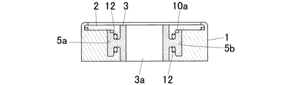
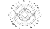
図1〜図5は、実施例1に係るロータリーダンパを示す図である。このロータリーダンパは、流路10が中空の軸部材3に設けられている。より詳細には、流路10が、軸部材3に形成される環状の溝10aと、該溝10aから分岐し、2つの室7a,7bにそれぞれ開口する溝10b,10cとからなり、軸部材3の中空部分3aを迂回した態様で設けられている(図5参照)。
1 to 5 are diagrams illustrating a rotary damper according to a first embodiment. In this rotary damper, the
本実施例に係るロータリーダンパは、以下のように動作する。すなわち、本体ケース1が固定され、軸部材3が一方向(図5において時計回り方向)に回転した場合、押圧部材として機能する2つのベーン4a,4bが軸部材3とともに、軸部材3を中心として一方向に回転する。これにより、2つの室6a,6b内の粘性液体が各ベーン4a,4bによって押圧される。このとき、各室6a,6b内の粘性液体は、通路8の大孔部8aに流れ込むが、弁体9が通路8を閉鎖するため、通路8を経由して別の2つの室7a,7b内へ流入することができず、本体ケース1と各ベーン4a,4bとの間に形成される僅かな隙間を通って各室7a,7b内へ流入する。したがって、このときに粘性液体は大きな抵抗を生じる。
The rotary damper according to the present embodiment operates as follows. That is, when the
本体ケース1と各ベーン4a,4bとの間に形成される隙間の大きさにばらつきがある場合に、各ベーン4a,4bが一方向に回転すると、各ベーン4a,4bによって押圧された粘性液体が流入する2つの室7a,7bの内圧が均一でなくなるが、本実施例では、これらの室7a,7b間でのみ粘性液体の流通を可能にする流路10が設けられているため、これらの室7a,7b間で粘性液体が流路10を通って流通することにより、これらの室7a,7bの内圧を均一にすることができる。したがって、本体ケース1内において、様々な箇所に形成される隙間の大きさにばらつきがある場合でも、制動特性のばらつきを抑制することができ、また、軸部材3の位置がずれて軸部材3がシール部材12を過剰に圧迫すること及びそれにより粘性液体の漏れが生じることを防止することもできる。
When the gaps formed between the
各ベーン4a,4bが逆方向(図5において反時計回り方向)に回転したときには、2つの室7a,7b内の粘性液体が各ベーン4a,4bによって押圧される。このとき、各室7a,7b内の粘性液体は、通路8の小孔部8bに流れ込み、弁体9を弁座から離間させ、通路8を開放するため、通路8を経由して別の2つの室6a,6b内へ流入する。通路8は、そこを流れる粘性液体に抵抗が生じないように設計されているため、このときに生じる粘性液体の抵抗は小さい。
When the
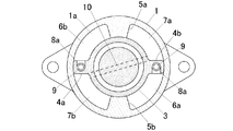
図6は、実施例2に係るロータリーダンパを示す図である。このロータリーダンパは、流路10が中空でない軸部材3に設けられている。この流路10は、軸部材3を貫通し、かつ両端がそれぞれ2つの室7a,7bに開口する穴からなる(図6参照)。
FIG. 6 is a diagram illustrating the rotary damper according to the second embodiment. The rotary damper is provided on the
本体ケース1と各ベーン4a,4bとの間に形成される隙間の大きさにばらつきがある場合には、各ベーン4a,4bが一方向(図6において時計回り方向)に回転すると、各ベーン4a,4bによって押圧された粘性液体が流入する2つの室7a,7bの内圧が均一でなくなるが、本実施例でも、実施例1と同様に、これらの室7a,7b間でのみ粘性液体の流通を可能にする流路10が設けられているため、これらの室7a,7b間で粘性液体が流路10を通って流通することにより、これらの室7a,7bの内圧を均一にすることができる。
When the size of the gap formed between the
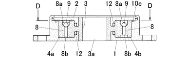
図7及び図8は、実施例3に係るロータリーダンパを示す図である。このロータリーダンパは、流路10が本体ケース1に設けられている。より詳細には、流路10が、本体ケース1に形成される環状の溝10eと、該溝10eから分岐し、2つの室7a,7bにそれぞれ開口する溝10f,10gとからなり、軸部材3の中空部分3aを迂回した態様で設けられている(図8参照)。
7 and 8 are diagrams illustrating the rotary damper according to the third embodiment. In the rotary damper, a
本体ケース1と各ベーン4a,4bとの間に形成される隙間の大きさにばらつきがある場合には、各ベーン4a,4bが一方向(図8において時計回り方向)に回転すると、各ベーン4a,4bによって押圧された粘性液体が流入する2つの室7a,7bの内圧が均一でなくなるが、本実施例でも、実施例1と同様に、これらの室7a,7b間でのみ粘性液体の流通を可能にする流路10が設けられているため、これらの室7a,7b間で粘性液体が流路10を通って流通することにより、これらの室7a,7bの内圧を均一にすることができる。
When the size of the gap formed between the
図9及び図10は、実施例4に係るロータリーダンパを示す図である。このロータリーダンパは、流路10が蓋部材2に設けられている。より詳細には、流路10が、蓋部材2に形成される環状の溝10hと、該溝10hから分岐し、2つの室にそれぞれ開口する溝10i,10jとからなり、軸部材3の中空部分3aを迂回した態様で設けられている(図9及び図10参照)。
9 and 10 are diagrams illustrating the rotary damper according to the fourth embodiment. In this rotary damper, the
本体ケース1と各ベーン4a,4bとの間に形成される隙間の大きさにばらつきがある場合には、各ベーン4a,4bが一方向に回転すると、各ベーン4a,4bによって押圧された粘性液体が流入する2つの室7a,7bの内圧が均一でなくなるが、本実施例でも、実施例1と同様に、これらの室7a,7b間でのみ粘性液体の流通を可能にする流路10が設けられているため、これらの室7a,7b間で粘性液体が流路10を通って流通することにより、これらの室7a,7bの内圧を均一にすることができる。
When the size of the gap formed between the
図11及び図12は、実施例5に係るロータリーダンパを示す図である。このロータリーダンパは、流路10が中間部材11に設けられている。より詳細には、流路10が、中間部材11に形成される環状の溝10kと、該溝10kから分岐し、2つの室7a,7bにそれぞれ開口する穴10m,10nとからなり、軸部材3の中空部分3aを迂回した態様で設けられている(図12参照)。
11 and 12 are diagrams illustrating the rotary damper according to the fifth embodiment. In this rotary damper, the
本体ケース1と各ベーン4a,4bとの間に形成される隙間の大きさにばらつきがある場合には、各ベーン4a,4bが一方向に回転すると、各ベーン4a,4bによって押圧された粘性液体が流入する2つの室7a,7bの内圧が均一でなくなるが、本実施例でも、実施例1と同様に、これらの室7a,7b間でのみ粘性液体の流通を可能にする流路10が設けられているため、これらの室7a,7b間で粘性液体が流路10を通って流通することにより、これらの室7a,7bの内圧を均一にすることができる。
When the size of the gap formed between the
1 本体ケース
2 蓋部材
3 軸部材
3a 中空部分
4a,4b ベーン
5a,5b 隔壁
6a,6b,7a,7b 室
8 通路
8a 大孔部
8b 小孔部
9 弁体
10 流路
10a〜10c,10e〜10g,10h〜10k 溝
10m,10n 穴
11 中間部材
12 シール部材
DESCRIPTION OF
Claims (4)
各押圧手段が一方向に回転したときに、各押圧手段によって押圧される前記粘性液体を収容する複数の室間で前記粘性液体の流通を可能にする流路は設けずに、そのときに、各押圧手段によって押圧された前記粘性液体が流入する複数の室間でのみ前記粘性液体の流通を可能にする流路を設けたことを特徴とするロータリーダンパ。 A shaft member provided in the main body case, a viscous liquid filled in the main body case, and a plurality of pressing means provided in the main body case for pressing the viscous liquid by rotating around the shaft member And the viscosity generated when each pressing means rotates in the opposite direction and presses the viscous liquid, rather than the resistance of the viscous liquid that occurs when each pressing means rotates in one direction and presses the viscous liquid. A rotary damper having a control mechanism for reducing the resistance of the liquid,
When each pressing means rotates in one direction, without providing a flow path that allows the viscous liquid to flow between the plurality of chambers that contain the viscous liquid pressed by each pressing means, A rotary damper characterized in that a flow path is provided that allows the viscous liquid to flow only between a plurality of chambers into which the viscous liquid pressed by each pressing means flows.
Priority Applications (1)
| Application Number | Priority Date | Filing Date | Title |
|---|---|---|---|
| JP2008214989A JP4982449B2 (en) | 2008-08-25 | 2008-08-25 | Rotary damper |
Applications Claiming Priority (1)
| Application Number | Priority Date | Filing Date | Title |
|---|---|---|---|
| JP2008214989A JP4982449B2 (en) | 2008-08-25 | 2008-08-25 | Rotary damper |
Publications (2)
| Publication Number | Publication Date |
|---|---|
| JP2010048386A true JP2010048386A (en) | 2010-03-04 |
| JP4982449B2 JP4982449B2 (en) | 2012-07-25 |
Family
ID=42065630
Family Applications (1)
| Application Number | Title | Priority Date | Filing Date |
|---|---|---|---|
| JP2008214989A Active JP4982449B2 (en) | 2008-08-25 | 2008-08-25 | Rotary damper |
Country Status (1)
| Country | Link |
|---|---|
| JP (1) | JP4982449B2 (en) |
Cited By (2)
| Publication number | Priority date | Publication date | Assignee | Title |
|---|---|---|---|---|
| JP2012140977A (en) * | 2010-12-28 | 2012-07-26 | Shiroki Corp | Damping device |
| CN107419947A (en) * | 2017-09-15 | 2017-12-01 | 成都市新筑路桥机械股份有限公司 | A kind of rotary damper |
Citations (6)
| Publication number | Priority date | Publication date | Assignee | Title |
|---|---|---|---|---|
| JPH05280568A (en) * | 1991-08-09 | 1993-10-26 | Kayaba Ind Co Ltd | Rotary damper |
| JPH11159561A (en) * | 1997-11-28 | 1999-06-15 | Unisia Jecs Corp | Rotary damper |
| JP2000120748A (en) * | 1998-10-16 | 2000-04-25 | Fuji Seiki Co Ltd | Rotary damper |
| JP2004060685A (en) * | 2002-07-25 | 2004-02-26 | Tok Bearing Co Ltd | Multilayer damper device |
| JP2004068945A (en) * | 2002-08-07 | 2004-03-04 | Tok Bearing Co Ltd | Rotary damper with multi-layered shaft |
| JP2007085503A (en) * | 2005-09-26 | 2007-04-05 | Somic Ishikawa Inc | Motion control device |
-
2008
- 2008-08-25 JP JP2008214989A patent/JP4982449B2/en active Active
Patent Citations (6)
| Publication number | Priority date | Publication date | Assignee | Title |
|---|---|---|---|---|
| JPH05280568A (en) * | 1991-08-09 | 1993-10-26 | Kayaba Ind Co Ltd | Rotary damper |
| JPH11159561A (en) * | 1997-11-28 | 1999-06-15 | Unisia Jecs Corp | Rotary damper |
| JP2000120748A (en) * | 1998-10-16 | 2000-04-25 | Fuji Seiki Co Ltd | Rotary damper |
| JP2004060685A (en) * | 2002-07-25 | 2004-02-26 | Tok Bearing Co Ltd | Multilayer damper device |
| JP2004068945A (en) * | 2002-08-07 | 2004-03-04 | Tok Bearing Co Ltd | Rotary damper with multi-layered shaft |
| JP2007085503A (en) * | 2005-09-26 | 2007-04-05 | Somic Ishikawa Inc | Motion control device |
Cited By (3)
| Publication number | Priority date | Publication date | Assignee | Title |
|---|---|---|---|---|
| JP2012140977A (en) * | 2010-12-28 | 2012-07-26 | Shiroki Corp | Damping device |
| CN107419947A (en) * | 2017-09-15 | 2017-12-01 | 成都市新筑路桥机械股份有限公司 | A kind of rotary damper |
| CN107419947B (en) * | 2017-09-15 | 2023-05-23 | 成都市新筑交通科技有限公司 | Rotary damper |
Also Published As
| Publication number | Publication date |
|---|---|
| JP4982449B2 (en) | 2012-07-25 |
Similar Documents
| Publication | Publication Date | Title |
|---|---|---|
| JP2020101290A (en) | Valve device and cooling system | |
| JP4982449B2 (en) | Rotary damper | |
| JP4426538B2 (en) | Rotary joint | |
| US11767908B2 (en) | Lubricant transfer ring having a plurality of chambers | |
| WO2007136869A3 (en) | Fast-acting fluid control valve | |
| JP6023533B2 (en) | Rotary damper | |
| JP2009185846A (en) | Damper device | |
| JP6150737B2 (en) | Damper device | |
| JP4911684B2 (en) | Rotating damper | |
| JP2021143743A (en) | Rotary valve | |
| JP2006189165A (en) | Valve device | |
| JP4837510B2 (en) | Rotary damper | |
| JP6647967B2 (en) | One-way rotary damper | |
| JP2015227719A (en) | Simple self-supporting mechanism | |
| JP7175852B2 (en) | rotary damper | |
| EP4036444A1 (en) | Spool valve | |
| JP5546147B2 (en) | Rotary damper | |
| JP7423434B2 (en) | segment seal | |
| EP4230899A1 (en) | Sliding component | |
| JP5805007B2 (en) | Channel switching mechanism | |
| JP2009127699A (en) | Hydraulic motion control device | |
| JP2018024046A (en) | Rotary cylinder | |
| JP5469772B2 (en) | Rotary damper | |
| JP2005249007A (en) | Rotary joint | |
| JP2009185901A (en) | Rotary damper |
Legal Events
| Date | Code | Title | Description |
|---|---|---|---|
| A621 | Written request for application examination |
Free format text: JAPANESE INTERMEDIATE CODE: A621 Effective date: 20110502 |
|
| A977 | Report on retrieval |
Free format text: JAPANESE INTERMEDIATE CODE: A971007 Effective date: 20120326 |
|
| TRDD | Decision of grant or rejection written | ||
| A01 | Written decision to grant a patent or to grant a registration (utility model) |
Free format text: JAPANESE INTERMEDIATE CODE: A01 Effective date: 20120330 |
|
| A01 | Written decision to grant a patent or to grant a registration (utility model) |
Free format text: JAPANESE INTERMEDIATE CODE: A01 |
|
| A61 | First payment of annual fees (during grant procedure) |
Free format text: JAPANESE INTERMEDIATE CODE: A61 Effective date: 20120423 |
|
| FPAY | Renewal fee payment (event date is renewal date of database) |
Free format text: PAYMENT UNTIL: 20150427 Year of fee payment: 3 |
|
| R150 | Certificate of patent or registration of utility model |
Ref document number: 4982449 Country of ref document: JP Free format text: JAPANESE INTERMEDIATE CODE: R150 Free format text: JAPANESE INTERMEDIATE CODE: R150 |
|
| R250 | Receipt of annual fees |
Free format text: JAPANESE INTERMEDIATE CODE: R250 |
|
| R250 | Receipt of annual fees |
Free format text: JAPANESE INTERMEDIATE CODE: R250 |
|
| R250 | Receipt of annual fees |
Free format text: JAPANESE INTERMEDIATE CODE: R250 |
|
| R250 | Receipt of annual fees |
Free format text: JAPANESE INTERMEDIATE CODE: R250 |
|
| R250 | Receipt of annual fees |
Free format text: JAPANESE INTERMEDIATE CODE: R250 |
|
| R250 | Receipt of annual fees |
Free format text: JAPANESE INTERMEDIATE CODE: R250 |
|
| R250 | Receipt of annual fees |
Free format text: JAPANESE INTERMEDIATE CODE: R250 |
|
| S111 | Request for change of ownership or part of ownership |
Free format text: JAPANESE INTERMEDIATE CODE: R313113 |
|
| R350 | Written notification of registration of transfer |
Free format text: JAPANESE INTERMEDIATE CODE: R350 |
|
| R250 | Receipt of annual fees |
Free format text: JAPANESE INTERMEDIATE CODE: R250 |
|
| R250 | Receipt of annual fees |
Free format text: JAPANESE INTERMEDIATE CODE: R250 |
|
| R250 | Receipt of annual fees |
Free format text: JAPANESE INTERMEDIATE CODE: R250 |